Embed Size (px)
Citation preview

CCCooolllooouuurrr TTTVVV
SSSeeerrrvvviiiccceee MMMaaannnuuuaaalll

2
Model No: 21PZP1MKI-ANZVersion 1.0
CHASSIS: TD171
MODEL: 21PZP1MKI/ANZ

3
Model No: 21PZP1MKI-ANZVersion 1.0
CONTENT SAFETY NOTICE ................................................................................................................................... 4 GENERAL DESCRIPTION .................................................................................................................... 5 TECHNICAL SPECIFICATION............................................................................................................. 5 GENERAL SPECIFICATION................................................................................................................. 6 CHASSIS BLOCK DIAGRAM ............................................................................................................... 7 FAULT FINDING TREES....................................................................................................................... 8 IC BLOCK DIAGRAM ......................................................................................................................... 15 ADJUSTMENT MODE ......................................................................................................................... 64 EXPLODED VIEW AND PART LIST ................................................................................................. 66 BOM LIST ............................................................................................................................................. 67 CIRCUIT DIAGRAM............................................................................................................................ 73

4
Model No: 21PZP1MKI-ANZVersion 1.0
SAFETY NOTICE
SAFETY PRECAUTION 1. An isolation transformer should be connected in the power line between the receiver and the AC
line when a service is performed on the primary of the converter transformer of the set. 2. Comply with all caution and safety-related notes provided on the cabinet back, inside the cabinet,
on the chassis or the picture tube. 3. When replacing a chassis in the cabinet, always be certain that all the protective devices are
installed properly, such as, control knobs, adjustment covers or shields, barriers, isolation resistor-capacitor networks etc.. Before returning any television to the customer, the service technician must be sure that it is completely safe to operate without danger of electrical shock.
X-RADIATION PRECAUTION The primary source of X-RADIATION in television receiver is the picture tube. The picture tube is specially constructed to limit X-RADIATION emissions. For continued X-RADIATION protection, the replacement tube must be the same type as the original including suffix letter. Excessive high voltage may produce potentially hazardous X-RADIATION. To avoid such hazards, the high voltage must be maintained within specified limit. Refer to this service manual, high voltage adjustment for specific high voltage limit. If high voltage exceeds specified limits, take necessary corrective action. Carefully follow the instructions for +B1 volt power supply adjustment, and high voltage check to maintain the high voltage within the specified limits. PRODUCT SAFETY NOTICE Product safety should be considered when a component replacement is made in any area of a receiver. Components indicated by mark in the parts list and the schematic diagram designate components in which safety can be of special significance. It is particularly recommended that only parts designated on the parts list in this manual be used for component replacement designated by mark. No deviations from resistance wattage or voltage ratings may be made for replacement items designated by mark.

5
Model No: 21PZP1MKI-ANZVersion 1.0
GENERAL DESCRIPTION
AKTP01/02 chassis series are applied A14T02/A14T02a respectively which uses mainly TOSHIBA’ advanced UOC-ultimate chip TMPA8803/8821/8851 and I2C-bus controlled IC with combination of micro controller and small signal processor, the TMPA8803/8821/8851 series feature high-integration, high performance-to-price ratio and high-reliability and advanced functions with fewer external components, which provide much convenience for manufacturing and technical service. Table 1: A14T02 mainly ICs and functions
Position Type Function Description RemarkN204 8851CPNG6EG1 Micro controller and small signal
processor (UOC)
V501 Driver Transistor (C4460) Power Supply T501 BCK-65-10 D3 Isolate Transformer A101 ET-5C1E-EV200K Tuner T402 BSC25-05N2135 FlyBack Transformer N701 TA1343NG Sound Processor N702 TDA7496SA Sound power amplifier N402 STV9302 Vertical Scan Output Stage Circuit V411 TT2496 Horizontal Driver TST N901 ATMEL 24C16 EEPROM IC Z101 K2955 Saw Filter
N203/N207 TC4053 AV1/AV2 Switch
TECHNICAL SPECIFICATION
Test Item Conditional TD171
AC Operating Range
RF&AV signal input with sound loud speaker (volume maximum) & Picture set in Dynamic mode
115Vac ~ 240Vac
Philips or Mono-scope pattern signal with howling sound Contrast & Brightness set in Maximum, sound increase maximum
100Watts Total Power Consumption
Standby Mode 14 Watts
Brightness & contrast set in Maximum Min: 26.2KVdc
Typical Design value Average: 26.5KVdc EHT
Brightness &contrast Minimum Max: 27.8KVdc Anode Current Brightness &contrast Maximum IABL = 1.08mA Heater Voltage TV operate normally V Heater = 6.2Vac B+ Normal operating VB+ = 112Vdc Sound power output
RF signal input broadcasting at 217.25MHz/BG/DK(1KHz) Volume is maximum
V = 9.2Vrms P = 10Watts X 2

6
Model No: 21PZP1MKI-ANZVersion 1.0
GENERAL SPECIFICATION
14” 70W MAX Power consumption 21” 100W MAX Receive system DK/BG Color system PAL/ SECAM/ NTSC Vision intermediate frequency 38.9MHz
5.5 MHz(B/G) Inter-carrier frequency
6.5MHz(D/K) Chroma if frequency PAL 34.47/ 35.32MHz Antenna type DIN TYPE 75 Ohm
VHF-L: 46.25-161.25MHz VHF-H: 168.25-463.25MHz Channel receiving UHF: 471.25-855.25MHz
Tuning system VS tuning AV IN/ OUT 2 AV STEREO IN + 1 AV STEREO OUT Component IN 1 YUV-Component IN
VIDEO IN ----1.0 0.2Vp-p 75 Ohm AUDIO IN ----0-2V (RMS) VIDEO OUT ----1.0 0.2Vp-p 75 Ohm AV IN/ OUT specification
AUDIO OUT ---- 0-2V (RMS)
OSD language English, Russian, Turkish, French, Spanish, Vietnamese, Indonesian, Arabian, Persian
Audio output power > 8W (1KHz, 0.5V INPUT, 10% THD Safety authentication standard CB LED indicator Power ON Hand set type HS08 Hans set power supply Pin AAx2 Color picture tube 14” 21” 90 degree tube Remote control distance 5m

7
Model No: 21PZP1MKI-ANZVersion 1.0
CHASSIS BLOCK DIAGRAM

8
Model No: 21PZP1MKI-ANZVersion 1.0
FAULT FINDING TREES 1. Three-None (no raster, no picture, no sound) This failure is mainly caused by big-power circuit such as power supply, horizontal scanning, vertical scanning. The detail checking and repairing steps are as follow.
0V
4.5-5.5V
YES
0V
>1V
0.6V
300V
NO
YES
0V
300V
0V
0V
115V
No variation
Normal
115V
0V
Others
24V
2V
9V
115V
LOW
NO variation
<50V
Test the voltage of C563
Cut off R449
Test other voltage such as 188V, 24V, and 12V
V551,VD551,RP551,V904, VD517,V900,V511
Check VD556,C563
Recover W560, unplug XZ411 for a While, then test the voltage of C563
Check V411,T402,T401, Deflection coil
Check L414, Deflection coil
Voltage of C507
Check if V501 collect-emitter Was broken down
Check R502,F501,power Switch, AC cord and plug
Check the voltage of V501 collector
Check V501,V512,F501,R502,VD503 Check T501
Test voltage of V501 base
Check T501,VD517, C515,C517,V411, VD552,VD414 C415,C416,T402 C412
Check if it get right When cut off V900
Test the voltage of N204 pin64
CPU has sent the Power-off signal
Check if V900 is broken down
Check V501
Check R564,V551,VD551 VD515,V511, V512,R572
N204 pin43 voltage
N204 pin13 voltage
Check Z901,C901, C902,N204
V444 pin C voltage
Check VD553,C559, R437,C430,T401, C415,V411
Check R320,V444
Check T402
Check V411 pin C voltage
Check T402,V411,R449
Others
115V
0V

9
Model No: 21PZP1MKI-ANZVersion 1.0
2. Two-None (no picture, no sound) The failure shows that the set does not display the picture but it has noise wave or blue background or OSD on the screen. This means that the circuits of power supply, horizontal scanning, vertical scanning and video amplification are normal and they are not considered in the repairing. The failures are mainly in the small signal processing circuits. Before checking these circuits, a kind of practical test method is introduced. It is called “Signal-input way”. The detail is described as follow: We can use the resistance function of an analog multimeter, connect the red pole (negative in ohm scope) on the circuit board ground, then touch softly the test point with another pole (black pole) in ohm scope meanwhile observe the reactivity on the output device. Note: In the TV test, we mainly observe the noise wave on the CRT and listen to the noise voice liking as “Ka…..Ka” from the loudspeakers.
a. No picture
Out of the “ 0-33V ” range
0V
NO
No picture
Check the “+9V” voltage on A101
Check RF signal input and adaptor
Check N901, A101
Check V103,V102,R907,R908,N901,A101
Check the “VT” voltage when auto searching
Check R102, C101, A101
The voltage between VL and BH vary from 0V to 9V or not when auto searching
Check R553, N904,C973
The voltage on the C923
Check the voltage on the C923
Check ,V901,N204, R902, R903 ,R909,C928,C922
Check if A101 has input signal
0V
YES
In the “0-33V” range
5V
<33V
=33V
0-33V

10
Model No: 21PZP1MKI-ANZVersion 1.0
0V >3.8V
<2V Exam the voltage of “ AGC ” on A101 without antenna
Check R119, R213, R101,C104,A101,N204 Test the voltage on pin 14,17,25,29, 49 of N204
NO
YES
<2V
YES
NO
0V
YES
Check C311, C306, 302, C209, C204, C238, C230 Test the voltage on pin 44 and pin36 of N204
Check N902, N204
Check N902, N204, C311, C306, 302, C209, C204, C238, C230
Observe if there is snow-noise-wave disturbance on the CRT via using “Signal-input way ” by touching pin 43 and pin 42 of N204
Test if there is the sync signal on the pin 9 of N204
Check C212, A101, N204
Observe if there is snow-noise-wave disturbance on the CRT via using “ Signal-input way ” by touching pin 24 of N204
Check L901, R946, VD902, V902
Observe if these is snow-noise-wave disturbance on the CRT via using “ Signal-input way ” by touching pin 50, pin51, pin of N204
Check R226,R237,R238,V601,V611,V621 ,N204
9V
5V
NO
NO

11
Model No: 21PZP1MKI-ANZVersion 1.0
b. No sound In this kind of failure, first of all we should observe if there is the picture on the CRT. It proves the small signal circuit to work correctly with the picture on the CRT and we only check the sound signal processing and sound amplification circuit. The repairing method (B1) may be referred without picture. The detail checking and repairing steps are as follow. Note: Before repairing, assure that the volume is on and the state of set is in “TV”.
<5V YES
YES
NO
NO
<9V YES NO
YES
YES
YES
NO Hear if there is the voice liking “Ka…Ka ” in the loudspeaker via using “ Signal-input way ” by touching pin 53 of N201
Check N202,R231,C214,N201
Hear if there is the voice liking “Ka…Ka ” in the loudspeaker via using “ Signal-input way ” by touching pin4,15of N252
Hear if there is the voice liking “Ka…Ka ” in the loudspeaker via using “ Signal-input way ” by touching pin 1 of N201
Check R231, C214, N201
Check D901, N252,N203
The voltage on pin 9,10,11of N252
Check 9V-power supply
Hear if there is the voice liking “Ka…Ka ” in the loudspeaker via using “ Signal-input way ” by touching pin 2 of N711
Check VD552,R910,C700,T501,N701
The voltage on pin 16 of N252
Hear if there is the voice liking “Ka…Ka ” in the loudspeaker via using “ Signal-input way ” by touching pin 2,5 of N252
Check C706,C716,N252
Hear if there is the voice liking “Ka…Ka ” in the loudspeaker via using “ Signal-input way ” by touching pin 2 of N701
The voltage on pin 8 of N701
Check N203,N201,V922,R210,R202
Check C706,C705, R203
Check SP301, SP302, N711
NO
9V
9V 24V
NO

12
Model No: 21PZP1MKI-ANZVersion 1.0
3. Only horizontal line in the middle of the screen: If vertical deflection circuit does not work, this kind of failure will happen. In deflection yoke, there only has horizontal sweeping, the electron beam in the CRT only moves in the horizontal orientation, so form this failure. (While checking horizontal and vertical deflection circuit’s failure, we have better to use an oscilloscope.)
Abnormal
Normal
Normal
Abnormal 24V
0V
Abnormal
Normal
The waveform on the pin 16 of N204
Measuring the waveform on the deflection yoke
Check C303,R113,N204 The voltage on pin 3 of N402
Check VD434, VD554, N402
Check N402
Measuring the waveform on pin 1 of N402
Check R328, C448, N402, N204
Measuring the waveform on pin 5 of N402
Check R442, C413, VD433, XZ411, deflection yoke
Abnormal
The deflection yoke on the CRT

13
Model No: 21PZP1MKI-ANZVersion 1.0
4. Only vertical line in the middle of the screen This is a dangerous failure. It probable causes flashover and smoking inside the set. Don’t let your TV work for a long time as this failure appears. Because the electron beam can not move in the horizontal orientation, the failure should be in the horizontal deflection circuit. We mainly check the open-circuit fault in horizontal deflection circuit. The detail checking and repairing steps are as follow:
5. UOC does not work In television, remote-control system is similar with the computer system. In theory, it can work if it holds two conditions as follow: The power supply: In general, it is 5V, the error is not above 10% and the disturbance pulse is as small as possible. The clock pulse: In TMPA88XX circuit, the clock pulse is generated by pin 6 / pin 7 of N204 and 12M crystal oscillator. Television’s remote-control system also needs reset circuit that can preset the values in internal register. The circuit around pin 5 of N204 is called auto-reset circuit. If UOC detects errors in resetting, it will come to the state of program protected. The detail checking and repairing steps are as follow:
YES
YES NO
Vertical line
Repair CRT The horizontal yoke is opened or not
Whether “ XZ411” is opened
Check if there is bad solder between XZ411, and the main board
Check L414, C412, C415, C416 especial in inductive components and connector
NO
4.98V
<4.98V
=3.6V
<4.98V
YES
=5V
NO
<5V 5V
N204 does not work
The voltage on the pin 9, pin44, pin55 of N204
Observe if there is sine wave on the pin 6 or pin 7 of N204 with an oscilloscope
Check the voltage on the positive pole of L901
NO YES
4.98V
4.98V
Check alternant voltage on secondary coil of T501, Check Z901, N204
Check R939,VD922 Check the voltage on the pin 5 of N204
Check T501, VD553, R558 Check N204 Check the voltage on the emitter of V902
Check the voltage on the positive pole of VD902
Check VD902, R947 Check R949, R945,V902
Check R945

14
Model No: 21PZP1MKI-ANZVersion 1.0
6. No OSD (On Screen Display) This failure is usually cause by the circuit of character generated and located. Most of reasons are that the horizontal and vertical flyback pulse signals do not come to UOC. We can judge this failure by measuring the wave of the character in an oscilloscope. The detail checking and repairing steps are as follow:
YES
NO
Check FBT T402, N402
No OSD
Check the wave on the pin 4 of FBT and N402 pin1
Check N204, N901

15
Model No: 21PZP1MKI-ANZVersion 1.0
IC BLOCK DIAGRAM IC 204 (I2C BUS-UOC Toshiba One Chip-A8851CPNG6EG1) Note: Login Factory Mode: Chassis Key Location Step to enter into factory Mode Remark
TV front Panel 1/ Press and hold key “V-“
User Remote 2/ After Volume=0, Press Key “Display”
8821 8823 8851 8853 User Remote 3/ To Exit press and release key “Display”
1. Language: English/ Arabic/ Farsi /Indonesian /Vietnamese /Spanish /French /Turkish /Russian or English
only. 2. Number of position: 256 or 200 3. Open/Close curtain when power On/Off 4. Automatic Search Memory/Manual Search/ Manual Fine Tuning and Skip function 5. Clock/OFF-timer/ON-timer and sleep timer function (120min.) 6. Sound: Treble, Bass, Balance & Super Woofer 7. Selectable picture (MILD/ NATURE/ PERSONAL/ DYNAMIC/ MOVIE/ STANDARD) and selectable sound (NEWS/SURROUND OFF/ MUSIC/ THEATRE/ EXTEND1/ EXTEND2). 8. Auto-Power-Off (If a vacant channel is tuned or TV broadcast for a day is finished, the TV will automatically turn off after about 15 minutes.) 9. No-Signal-Mute (When the system receives a TV signal from the aerial input which does not contain a video signal, the sound will be muted. This No-Signal-Mute feature does not operate in the blue background OFF mode. 10. Selectable screen size(STANDARD/WIDE/ZOOM) 11. Child lock function (CHANNEL LOCK/TV LOCK/PANEL LOCK/VOLUME FIX) 12. Calendar function (1900-2099)-Telephone book function 13. MESSAGE function 14. Quick View function 15. MUSIC MODE function 16. NOISE REDUCER function and BLACK STRETEH function 17. Game function 18. IF Frequency (38MHz、38.9MHz) 19. Multi system (PAL/SECAM/NTCS3.58/NTCS4.43) 20. 2 AV Input or 1 AV Input, S-VHS Input, YUV Input 21. EYE GUARD function 22. HOTEL MODE function 23. VS/ FS option 24. Local buttons (P+, P-, V+, V-, TV/AV, MENU, POWER) NOTE: Some item are option.

16
Model No: 21PZP1MKI-ANZVersion 1.0
A. BLOCK DIAGRAM:
16
SONUD PROCESSOR TA1343

17
Model No: 21PZP1MKI-ANZVersion 1.0
B. PIN NAME:
NO. Pin name I/O Function 1 BAND1 (VS)/EyeCare or X-ray (FS) I/O BAND data output 1 (VS)/EyeCare or X-ray
(FS) 2 BAND2(VS)/ DEGAUSSING Out BAND data output 2(VS)/ DEGAUSSING 3 KEY In Key input 4 VSS - GND connection 5 RESET In Reset signal input 6 XIN In 8 MHz oscillator connecting 7 XOUT Out 8 MHz oscillator connecting 8 TEST In GND connection 9 VDD In 5V power supply
10 VSS - GND connection 11 VSS - GND connection 12 FBP in In Input terminal for FBP 13 H out Out Output terminal for Horizontal driving pulse 14 HAFC 1 - Terminal To be connected capacitor for H AFC
filter 15 V saw - Terminal To be connected capacitor to generate
Vsaw signal 16 V out Out Output terminal for Vertical driving pulse 17 HVcc - Vcc terminal for DEF circuit 18 SECAM Fil - SECAM Filter 19 Cb in In Input terminal for Cb signal 20 Y in In Input terminal for Y signal 21 Cr in In Input terminal for Cr signal 22 TV GND - GND terminal for Digital block 23 C in In Input terminal for Chroma signal 24 V2 in In Input terminal for Video signal 25 TV DVcc - Vcc terminal for Digital block 26 V1 in In Input terminal for Video signal 27 ABCL In Input terminal for ABL/ACL control 28 AU out Out Output terminal for Audio signal 29 IF Vcc 9V - Vcc for terminal for IF Circuit 30 TV out Out Output terminal for detected PIF signal 31 SIF out Out Output terminal for detected SIF signal 32 Ext AU in In Input terminal for External Audio signal 33 H correct/SIF in In Input terminal for H correction and SIF 34 DC NF Out Terminal to be connected capacitor for DC
Negative Feedback from SIF Det output 35
PIF PLL -
Terminal to be connected with loop filter for PIF PLL. This terminal voltage is controlled PIF VCO frequency.
36 IF Vcc 5V - Vcc terminal for IF circuit. Supply 5V. 37 Reg Fil - Terminal to be connected capacitor for
stabilizing internal bias. 38 Deempha - Terminal to be connected capacitor for SIF Det
De-Emphasis. 39 IF AGC - Terminal to be connected with IF AGC filter. 40 IF GND - GND terminal for IF circuit. 41 IF in In Input terminals for IF signals. 42 IF in In Input terminals for IF signals.

18
Model No: 21PZP1MKI-ANZVersion 1.0
43 RF AGC Output terminal for RF AGC control level.
44 TV YC Vcc - Vcc terminal for Y/C circuit. Supply 5V. 45 Monitor out Out Output terminal for CVBS or Y signal selected
by BUS(Video SW). 46 Black Det - Terminal to be connected with Black Det filter
for black stretch. 47 Chroma PLL - Terminal to be connected with APC filter for
chroma demodulation. 48 Sync Output Out Sync Output 49 RGB Vcc - Vcc terminal for RGB circuit. Supply 5V. 50 R out Out Output terminal for R signal. 51 G out Out Output terminal for G signal. 52 B out Out Output terminal for B signal. 53 TV AGND - GND terminal for Analog block. 54 VSS - GND connection 55 VDD In 5V power supply 56
MUTE(Mo)/VIDEO1/2(St) Out Mono: mute/ Stereo: TV=0,AV1=2.5V,AV2=5V
57 SDA1 I/O IIC-BUS SDA1 58 SCL1 I/O IIC-BUS SCL1 59 Volume control or 50/60Hz Out Volume control(PWM) or 50/60Hz control 60 PWM Out PWM output 61 AV Control / MUTE Out Mono: AV
Control,AV1=0,AV2=5V/Stereo:Mute Output 62 H.SYNC In Horizontal sync signal input 63 REMOTE In Remote controller signal input 64 POWER I/O Power control & Check, On=Hi-
Z(input),Off=L(output)

19
Model No: 21PZP1MKI-ANZVersion 1.0
C/ SYSTEM: 1.REMOTE CONTROL
For Example: If Pin19 with diode
14 15 16 17 18 19 20 21 Pin 7 6 5 4 3 2 1 0 bit 0 0 0 0 0 1 0 0 CUSL 04 1 1 1 1 1 0 1 1 CUSH FB
2. BAND
BAND1(Pin1) BAND2(Pin2) VHF L L H VHF H H L UHF L L

20
Model No: 21PZP1MKI-ANZVersion 1.0
D. Mode 1.MOD(30)
Bit7: No Use Bit6-4:IF Frequency
Bit6 Bit5 Bit4 PIF Freq. 0 0 0 58.75MHz 0 0 1 45.75MHz 0 1 0 - 0 1 1 38.9MHz 1 0 0 38MHz 1 0 1 - 1 1 0 - 1 1 1 -
Bit3,2:AKB MODE Bit1,0:Cutoff Gain×10
2.OPT(C4)
Bit7: Mute of AV Switch Key 0: Port Mute ON 1: No Port Mute Bit6: Monitor Sync 0: Always TV Sync 1: Monitor Sync Bit5: TINT polarity select 0: Red 1: Green Bit4: VT DOWN No Signal Not VT Down of AFT when No Signal(=1) Bit3: AUDIO GAIN SW of 2in1 0: 927mVrms at 50KHz/dev 1: 500mVrms at 500KHz/dev Bit2: Select Screen 0: No Use 1: Used Bit1: RFAGC status when AV 0: Normal 1: When AV: RFAGC=00 Bit0: Ex-mute while Pos Change 0: Mute 1: No Mute
3.AV OPT(01) Bit7-2: No Use Bit1-0:AV Input Select
Bit1 Bit0 Description 0 0 0 TV/VIDEO1(S-VIDEO)/DVD 0 1 1 TV/ VIDEO1(S-VIDEO)/DVD/ VIDEO2 1 0 2 TV/ VIDEO1(S-VIDEO) 1 1 3 TV/ VIDEO1(S-VIDEO) / VIDEO2
4.OPT2(AA)
Bit7: Be used to set LOGO when BB 0:No Use 1:Used Bit6: SRY/SBY 0:SRY/SBY White 1:SRY/SBY Black Bit5: Chassis select 0:Mono PCB (Pin56 mute/ Pin61TV/AV) 1:Stereo PCB(Pin56 TV/AV/ Pin61mute) Bit4: Fjp-mute-exmute 0:no use 1:use Bit3: AV sound mute when B.B 0:No Use 1:Used Bit2: Fjp_mute_process 0: unused 1: decreasing Bit1: IF Frequency OPTION WHEN FS 0:38MHz 1:38.9MHz Bit0: Power on delay timer 0:No Use 1:delay 1S

21
Model No: 21PZP1MKI-ANZVersion 1.0
5. MOD0(82) Bit7-6: Shop-out Setting
Bit7 Bit6 SHOP-OUT 0 0 No Use 0 1 I 1 0 B/G 1 1 D/K
Bit5:Pin59 PWM 0:No Use 1:Used
Bit4:Pin2 DEGAUSSING 0:No Use 1:Used(FS status)
Bit3:Eye Care 0: No Use 1:Used(FS status)
Bit2:SECAM 0: No Use 1:Used
Bit1:Be used to VCO adjust 0: No Use 1:Used (This Bit Must Set 1)
Bit0:X-Ray protect(Pin1) 0:No Use 1:Used(FS status and Eye Care no use)
6.MOD1(21) Bit7: Extend mode attenuation 0:according to effect1 1:-5db
Bit6: Super woofer 0:No Use 1:Used
Bit5: sound menu 0:No Use 1:Used
Bit4: Sound system BG2 0: No Use 1:Used
Bit3: Sound system M 0: No Use 1:Used
Bit2: Sound system D/K 0: No Use 1:Used
Bit1: Sound system I 0: No Use 1:Used
Bit0: Sound system B/G 0: No Use 1:Used
7.MOD2(1F) Bit7-6: FS Tuner select
00 38.9MHz JINXIN UVL5705VEA(IC:KTS6029)/JINXIN UVL7605VEA(IC:TDA6509)
L:48.25-147.25 MHz(E2-S7)/M:154.25-423.25 MHz(S8-S36)/H:431.25-855.25 MHz(S37-CH57) 01 38.9MHz XIMEI FTDC3Y15BV03(IC:TDA6509)/GDC:EWT-5F3P1-E06W(IC:TDA6509)
L:48.25-140.25 MHz(E2-S6)/M:147.25-423.25 MHz(S7-S36)/H:431.25-855.25 MHz(S37-CH57) 10 38MHz XIMEI FTDC3Y15V03(IC:TDA6509)JINXIN UVL5705VCA(IC:KTS6029)/ JINXIN
UVL7605VCA(IC:TDA6509)
L:49.75-144.25 MHz(C1-Z5)/M:152.25-424.25 MHz(Z6-Z33)/H:432.25-863.25 MHz(Z34-C57) Bit5: Fjp_power_option 0:open TV directly 1: must use remote control to open TV Bit4: Select Telephone book 0: No Use 1: Used(Must use 16KEEPROM) Bit3: Close curtain when power off 0:No Use 1:Used
Bit2: Open curtain when power off 0:No Use 1:Used
Bit1: Position select 0:200Pos(8KE2PROM) 1:256Pos(16KE2PROM)
Bit0: Tuner select(VS or FS) 0: use VS Tuner 1:use FS Tuner

22
Model No: 21PZP1MKI-ANZVersion 1.0
8.LANG: English/ Arabic/ Farsi /Indonesian /Vietnamese /Spanish /French /Turkish /Russian(00) Bit7: Arabic 0: No Use 1:Used
Bit6: Farsi 0: No Use 1:Used
Bit5: Indonesian 0: No Use 1:Used
Bit4: Vietnamese 0: No Use 1:Used
Bit3: Spanish 0: No Use 1:Used
Bit2: French 0: No Use 1:Used
Bit1: Turkish 0: No Use 1:Used
Bit0: Russian 0: No Use 1:Used
9.EFFECT1(00) Bit7: This bit must be zero Bit6: ALS SW for TA1343 0:off 1:on
Bit5-4: ALS start point
Bit5 Bit4 0 0 220mV 0 1 380mV 1 0 525mV 1 1 770mV
Bit3: This bit must be zero Bit2: Input attenuation 0: 0 dB 1: 5dB Bit1-0: Input matrix
Bit1 Bit0 0 0 normal 0 1 Rch 1 0 Lch 1 1 reverse
10.EFFECT2(27)
Bit7: Bass boost 0:off 1:on Bit6: This bit must be zero Bit5-4: Woofer LPF
Bit5 Bit4 0 0 100Hz 0 1 125Hz 1 0 170Hz 1 1 210Hz
Bit3: No Use Bit2-0:Surround effect level 000:1
001:2 …… 111:7
11.HITZ/ HITW/HITZS/ HITWS HITZ: 50Hz ZOOM SIZE(35) HITW: 50Hz WIDE SIZE(20)

23
Model No: 21PZP1MKI-ANZVersion 1.0
HITZS: 60Hz ZOOM SIZE (00) HITWS: 60Hz WIDE SIZE (00)
12. NADJ(16)
Noise reducer adjustment
13. VPL(CE)
X-Ray protect adjustment
14. VOLM(64) HOTEL MODE: Volume maximal limit
15. LOGO(60) Bit7: DVD control option 0:same to AV1 1:same to AV2
Bit6: Pin59 control option 0:DVD control 1:50/60Hz control(50Hz: L/60Hz: H) Bit5: LOGO alphabet size 0: Small 1:Big Bit4-3: LOGO color
Bit1 Bit0 Color 0 0 red 0 1 white 1 0 purple 1 1 yellow
Bit2-0: LOGO horizontal position
16. LOGH(60) Bit7: When MUSIC MODE 0:Screen always B.B 1: Later 1 minute, screen disappear(with sound) Bit6: Hardware Mute 0:NO USE 1: USE Bit5: V-MUTE During POS change 0:Y-MUTE 1:RGB-CUT OFF DC Bit4-0: These seven bits are used to adjust the horizontal display position of logo smoothly
17. LOGV: Bit7-5: These three bits are used to adjust the OSD line position
000: fifth line 001: sixth line 010: seventh line 011: eighth line 100: ninth line 101: tenth line 110: eleventh line 111: twelfth line
Bit4-0: These five bits are used to adjust the vertical display position of logo smoothly
18. MENU COLOR A.CCOL /TCOL/BCOL/HCOL:
1) CCOL: Bit7: No use Bit6: Italic enable specification register 0: normal 1: italic Bit5-4: No use

24
Model No: 21PZP1MKI-ANZVersion 1.0
Bit3: DARK/ NORMAL 0:NORMAL 1:DARK Bit2-0: Color
Bit2 Bit1 Bit0 Color 0 0 0 Black 0 0 1 Blue 0 1 0 Green 0 1 1 Cyan 1 0 0 Red 1 0 1 purple 1 1 0 Yellow 1 1 1 White
2) TCOL Bit7:When Panel lock 0:unlock POWER key 1:lock all key Bit6: Italic enable specification register 0: normal 1: italic Bit5: Underline enable specification register 0:normal 1: underline Bit4:NO USE Bit3: DARK/ NORMAL 0:NORMAL 1:DARK Bit2-0: Set menu top character’s color
Bit2 Bit1 Bit0 Color 0 0 0 Black 0 0 1 Blue 0 1 0 Green 0 1 1 Cyan 1 0 0 Red 1 0 1 purple 1 1 0 Yellow 1 1 1 White
3) BCOL
Bit7: HOTEL MODE 0:USE 1:NO USE
Bit6: Tuner select 0:Normal Tuner 1:Use High Gain Tuner
Bit5: Pin60 PWM 0:NO USE 1: USED
Bit4: DVD-TV 0:TV 1:DVD/TV
Bit3: Message 0:NO USE 1:USED
Bit2: UHF P2/P3 option 0:P3 1:P2
Bit1-0:FS Tuner search speed
Bit1 Bit0 FS Tuner search speed 0 0 Normal 0 1 slow 1 0 fast

25
Model No: 21PZP1MKI-ANZVersion 1.0
4)HCOL Bit7: NO USE
Bit6: DARK/ NORMAL 0:NORMAL 1:DARK Bit5-4: NO USE Bit3: DARK/ NORMAL 0:NORMAL 1:DARK Bit2-0:
Bit2 Bit1 Bit0 Color 0 0 0 Black 0 0 1 Blue 0 1 0 Green 0 1 1 Cyan 1 0 0 Red 1 0 1 purple 1 1 0 Yellow 1 1 1 White
B)ACOL
Bit7: Transparency enable register for menu area 0: opacity 1: translucence Bit6-4: Main menu background select
Bit6 Bit5 Bit4 Color 0 0 0 Black 0 0 1 Blue 0 1 0 Green 0 1 1 Cyan 1 0 0 Red 1 0 1 purple 1 1 0 Yellow 1 1 1 White
Bit3:Transparency enable register for highlight area 0: opacity 1: translucence Bit2-0: Color select for highlight area
Bit2 Bit1 Bit0 Color 0 0 0 Black 0 0 1 Blue 0 1 0 Green 0 1 1 Cyan 1 0 0 Red 1 0 1 Purple 1 1 0 Yellow 1 1 1 White
MENU
PICTURE SOUND TUNING INSTILL FUNCTION
TCOL
CCOL
HCOL ACOL

26
Model No: 21PZP1MKI-ANZVersion 1.0
C)CALC (calendar Color:F9) Bit7: Date background 0: opacity 1: translucence Bit6-4: Date background color select
000:Black
001:Blue
010:Green
011:Cyan
100:Red
101:Purple
110:Yellow
111:White Bit3: Week background 0: opacity 1: translucence Bit2-0: Week background color select
000:Black
001:Blue
010:Green
011:Cyan
100:Red
101:Purple
110:Yellow
111:White
19.FSAD(C0) (FS Tuner address)
C0:0-0.1V
C2:OPEN or 0.2-0.3V
C4:0.4-0.6V
C6:0.9-1.0V
20.VADJ(00) Eye Care Range Adjustment 00-0A
21.SADJ(00) Eye Care Speed Adjustment 01-0A
22.SYNT(F1)
00-FF
23.SSYN(FA) 00-FF
24. LOGO/SCREEN SAVED(Use NO.5 BRTC Key) 1)LOGO address 770-77B
DEC 2003 SUN MON TUE WED THU FRI SAT
1 2 3 4 5 6 7 8 9 10 11 12 13
14 15 16 17 18 19 20 21 22 23 24 25 26 27 28 29 30 31
YEAR↑↓ MONTH← →
Bit2-0
Bit6-4

27
Model No: 21PZP1MKI-ANZVersion 1.0
2)A~Z
A B C D E F G H I J K L M 41 42 43 44 45 46 47 48 49 4
A 4
B 4
C 4
D
N O P Q R S T U V W X Y Z 4
E 4
F 50 51 52 53 54 55 56 57 58 59 5
A
3)a~z
a b c d e f g h i j k l m 80-21 80-22 80-
23 80-24
80-25
80-26
80-27
80-28
80-29
80-2A
80-2B
80-2C
80-2D
n o p q r s t u v w x y z
80-2E 80-2F 80-30 80-31 80-32 80-33 80-34 80-35 80-36 80-37 80-38 80-39 80-3A
4)0~9
0 1 2 3 4 5 6 7 8 9 30 31 32 33 34 35 36 37 38 39
25)Spacing 20 26)End00:
ITEM DATA REMARK ITEM DAT
A REMARK
RCUT 20 R CUT OFF SVM 00 SVM GCUT 20 G CUT OFF VBLK 00 V BLK Start/Stop BCUT 20 B CUT OFF VCEN 27 V CENTERING GDRV 40 G DRIVE EHT 24 V EHT/H ENT BDRV 40 B DRIVE UCOM 1C Miciom Control
CNTX 7F SUB CONTRAST MAX PYNX 2E NORMAL H.SYNC MAX
BRTC 48 SUB BRIGHT CENTER PYNN 18 NORMAL H.SYNC MIN
COLC 40 SUB COLOR for NTSC PYXS 22 SEARCH H.SYNC MAX
TNTC 40 SUB TINT CENTER PYNS 1E SEARCH H.SYNC MIN
COLP 00 SUB COLOR for PAL RCUTS 00 FOR YCbCr R CUTOFF
COLS 40 SUB COLOR for SECAM GCUTS 00 FOR YCbCr G CUTOFF
SCOL 07 SUB COLOR BCUTS 00 FOR YCbCr B CUTOFF
SCNT 0D Y-SUB CONTRAST GDRVS 00 FOR YCbCr G DRIVE
CNTC 58 SUB CONTRAST CENTER BDRVS 00 FOR YCbCr B DRIVE
CNTN 00 SUB CONTRAST MIN NOIS 01 HAFC CONTROL

28
Model No: 21PZP1MKI-ANZVersion 1.0
BRTX 35 SUB BRIGHT MAX AOPT 01 AV MODEL SELECT
BRTN 25 SUB BRIGHT MIN OPT2 AA OPT2 SELECT
COLX 3F SUB COLOR MAX WAIT 2F WAITING TIME IN THE OPEN CURTAIN
ST3 25 TV—3.58 SHARP CURC A5 CURTAIN CENTER
SV3 25 AV—3.58 SHARP CURS 02 STEPS OF THE
WIDTH OFCURTAIN FUNCTION
ST4 25 TV—4.43 SHARP AUSTP 04 When Mute off, Vol. ATT up step number
SV4 25 AV—4.43 SHARP MOD0 82 MODE 0
SVD 26 DVD SHARP CENTER MOD1 21 MODE1
SHPX 38 SUB SHARP MAX MOD2 1F MODE2
SHPN 15 SUB SHARP MIN OSDF 53 OSD WIDTH
TXCX 10 OSD CONTRAST MAX HITZ 35 50Hz SIZE ZOOM Vertical size
RGCN 1F OSD CONTRAST MIN HITW 20 50Hz SIZE WIDE Vertical size.
ABL 37 ABL SYSTEM HITZS 00 60Hz SIZE ZOOM Vertical size.
DCBS 33 A part of Video data in detail HITWS 00 60Hz SIZE WIDE
Vertical size.
CLTO 0B The data when TV mode & SOUND SYS!=M EFF1 00 SOUND EFFECT1
CLTM 4B The data when TV mode & SOUND SYS=M EFF2 27 SOUND EFFECT2
CLVO 4D The data when YUV mode & SOUND SYS!=M BASC 40 BASS CENTER
VALUE
CLVD 48 The data when YUV mode & SOUND SYS=M TREC 40 TREBLE CENTER
VALUE
DEF 01 A part of DEF COMP data in detail BALC 3F BALANCE CENTER
VALUE
SECD 18 SECAM mode WOFC 39 WOFFER CENTER VALUE
HPOS 13 50Hz HORIZONTAL PHASE NADJ 16 Noise
VP50 02 50Hz VERTICAL PHASE CCOL 03 Menu Color
HIT 2B 50Hz VERTICAL AMPLITUDE TCOL 07 Menu Color
HPS 02 60Hz HORIZONTAL PHASE BCOL 08 Menu Color
VP60 00 60Hz VERTICAL PHASE HCOL 06 Menu Color
HITS 02 60Hz VERTICAL AMPLITUDE ACOL 98 Menu Color
VLIN 0D 50Hz VERTICAL-LINEARILTY CALC F9 Calendar Color
VSC 09 50Hz VERTICAL-S CORRECTION A50 57 AV VOLUME50%
VLIS 02 60Hz VERTICAL-LINEARILTY A100 7F AVVOLUME100%
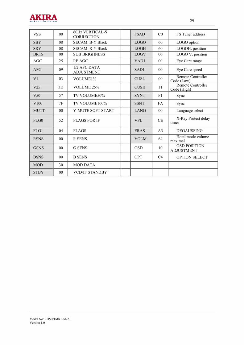
29
Model No: 21PZP1MKI-ANZVersion 1.0
VSS 00 60Hz VERTICAL-S CORRECTION FSAD C0 FS Tuner address
SBY 08 SECAM B-Y Black LOGO 60 LOGO option SRY 08 SECAM R-Y Black LOGH 60 LOGOH. position BRTS 00 SUB BRIGHNESS LOGV 00 LOGO V. position AGC 25 RF AGC VADJ 00 Eye Care range
AFC 09 1/2 AFC DATA ADJUSTMENT SADJ 00 Eye Care speed
V1 03 VOLUME1% CUSL 00 Remote Controller Code (Low)
V25 3D VOLUME 25% CUSH Ff Remote Controller Code (High)
V50 57 TV VOLUME50% SYNT F1 Sync
V100 7F TV VOLUME100% SSNT FA Sync
MUTT 00 Y-MUTE SOFT START LANG 00 Language select
FLG0 52 FLAGS FOR IF VPL CE X-Ray Protect delay timer
FLG1 04 FLAGS ERAS A3 DEGAUSSING
RSNS 00 R SENS VOLM 64 Hotel mode volume maximal
GSNS 00 G SENS OSD 10 OSD POSITION ADJUSTMENT
BSNS 00 B SENS OPT C4 OPTION SELECT
MOD 30 MOD DATA
STBY 00 VCD/IF STANDBY

30
Model No: 21PZP1MKI-ANZVersion 1.0
IC N702 (8W AUDIO POWER OUTPUT) TDA7496SA

31
Model No: 21PZP1MKI-ANZVersion 1.0

32
Model No: 21PZP1MKI-ANZVersion 1.0

33
Model No: 21PZP1MKI-ANZVersion 1.0

34
Model No: 21PZP1MKI-ANZVersion 1.0

35
Model No: 21PZP1MKI-ANZVersion 1.0
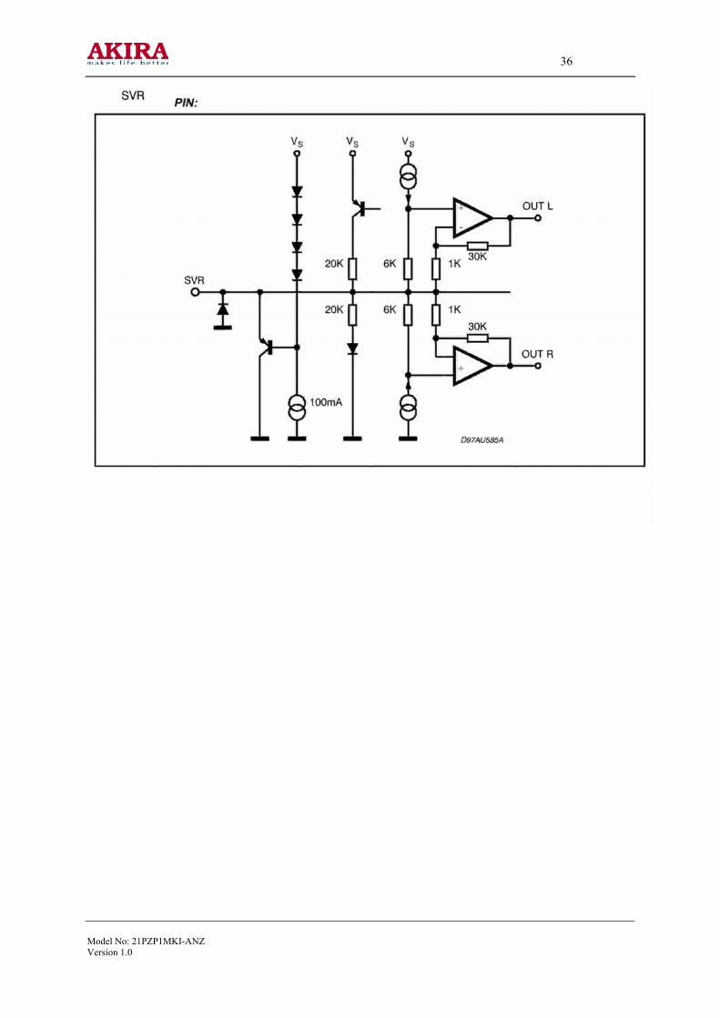
36
Model No: 21PZP1MKI-ANZVersion 1.0

37
Model No: 21PZP1MKI-ANZVersion 1.0

38
Model No: 21PZP1MKI-ANZVersion 1.0
IC 701 (SOUND PROCESSOR) TA1343NG

39
Model No: 21PZP1MKI-ANZVersion 1.0
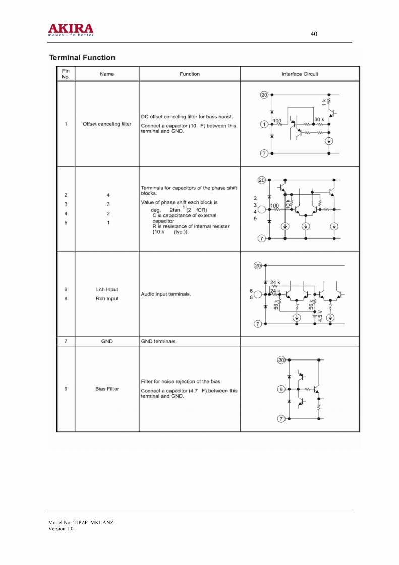
40
Model No: 21PZP1MKI-ANZVersion 1.0

41
Model No: 21PZP1MKI-ANZVersion 1.0

42
Model No: 21PZP1MKI-ANZVersion 1.0

43
Model No: 21PZP1MKI-ANZVersion 1.0

44
Model No: 21PZP1MKI-ANZVersion 1.0

45
Model No: 21PZP1MKI-ANZVersion 1.0

46
Model No: 21PZP1MKI-ANZVersion 1.0

47
Model No: 21PZP1MKI-ANZVersion 1.0

48
Model No: 21PZP1MKI-ANZVersion 1.0

49
Model No: 21PZP1MKI-ANZVersion 1.0

50
Model No: 21PZP1MKI-ANZVersion 1.0

51
Model No: 21PZP1MKI-ANZVersion 1.0

52
Model No: 21PZP1MKI-ANZVersion 1.0

53
Model No: 21PZP1MKI-ANZVersion 1.0

54
Model No: 21PZP1MKI-ANZVersion 1.0

55
Model No: 21PZP1MKI-ANZVersion 1.0

56
Model No: 21PZP1MKI-ANZVersion 1.0

57
Model No: 21PZP1MKI-ANZVersion 1.0

58
Model No: 21PZP1MKI-ANZVersion 1.0

59
Model No: 21PZP1MKI-ANZVersion 1.0

60
Model No: 21PZP1MKI-ANZVersion 1.0

61
Model No: 21PZP1MKI-ANZVersion 1.0

62
Model No: 21PZP1MKI-ANZVersion 1.0

63
Model No:21PZP1MKI-ANZVersion 1.0
IC N402 <VERTICAL OUTPUT> LA78040 (or STV9302)

64
Model No: 21PZP1MKI-ANZVersion 1.0
ADJUSTMENT MODE Geometry Adjustment Item Function Data
HPOS 50Hz HORIZONTAL PHASE 09
VP50 50Hz VERTICAL PHASE 03
HIT 50Hz VERTICAL AMPLITUDE 35
HPS 60Hz HORIZONTAL PHASE 03
VP60 60Hz VERTICAL PHASE 00
HITS 60Hz VERTICAL AMPLITUDE 02
VLIN 50Hz VERTICAL-LINEARILTY 0B
VSC 50Hz VERTICAL-S CORRECTION 06
VLIS 60Hz VERTICAL-LINEARILTY 00
VSS 60Hz VERTICAL-S CORRECTION 04 White Balance Adjustment
Item Function DATA
RCUT ALIGN RED OUT DC LEVEL 00 ~ FF
GCUT ALIGN GREEN OUT DC LEVEL 00 ~ FF
BCUT ALIGN BLUE OUT DC LEVEL 00 ~ FF
GDRV ALIGN GREEN OUT AC LEVEL 00 ~ 7F
BDRV ALIGN BLUE OUT AC LEVEL 00 ~ 7F
CNTX SUB CONTRAST MAX 7F
BRTC SUB BRIGHT CENTER 04
COLC SUB COLOR for NTSC 40
TNTC SUB TINT CENTER 40
COLP SUB COLOR for PAL 12
COLS SUB COLOR for SECAM 43
SCOL SUB COLOR 07
SCNT Y-SUB CONTRAST 0F
CNTC SUB CONTRAST CENTER 50
CNTN SUB CONTRAST MIN 10
BRTX SUB BRIGHT MAX 35
BRTN SUB BRIGHT MIN 25

65
Model No: 21PZP1MKI-ANZVersion 1.0
COLX SUB COLOR MAX 3F
BRTS SUB BRIGHNESS 00
ST3 TV—3.58 SHARP 25
SV3 AV—3.58 SHARP 25
ST4 TV—4.43 SHARP 25
SV4 AV—4.43 SHARP 25

66
Model No: 21PZP1MKI-ANZVersion 1.0
EXPLODED VIEW AND PART LIST

67
Model No: 21PZP1MKI-ANZVersion 1.0
BOM LIST Item No Part Name Qty Position CARBON RESISTOR
1 1/6W 4.7 1 R444 2 1/6W 33 1 R113 3 1/6W 68 1 R215
4
1/6W 100
17
R203 R204 R217 R221 R222 R223 R225 R229 R286 R287 R292 R294 R307 R318 R330 R901 R902
5 1/6W 150 3 R111 R201 R404 6 1/6W 180 1 R310 7 1/6W 220 6 R106 R107 R282 R306 R326 R938 8 1/6W 270 5 R205 R236 R237 R238 R325 9 1/6W 330 3 R607 R617 R627 10 1/6W 560 2 R320 R945 11
1/6W 1K
10
R283 R289 R517 R701 R710 R712 R900 R904 R925 R930
12 1/6W 1.5K 6 R1001 R115 R726 R727 R944 R946 13 1/6W 2K 1 R1002 14 1/6W 2.2K 3 R209 R212 R214 15 1/6W 3.3K 6 R202 R230 R244 R301 R446 R523 16 1/6W 3.9K 5 R108 R608 R618 R628 R916 17 1/6W 4.7K 6 R1003 R252 R255 R918 R919 R941 18 1/6W 5.6K 4 R443 R511 R905 R920 19 1/6W 8.2K 2 R322 R947 20 1/6W 9.1K 1 R1004
21
1/6W 10K 21
R102 R243 R280 R284 R290 R298 R321 R423 R448 R640 R704 R907 R908 R912 R922 R935 R939 R942 R950 R989 RVD904
22 1/6W 12K 1 R943
23
1/6W 15K
13
R1005 R210 R213 R216 R278 R285 R291 R293 R295 R299 R328 R424 R447
24 1/6W 22K 7 R279 R297 R480 R515 R557 R909 R929 25 1/6W 30K 1 R1006 26 1/6W 33K 3 R232 R903 R913 27 1/6W 39K 1 R721 28 1/6W 47K 3 R450 R635 R928 29 1/6W 68K 1 R101 30 1/6W 100K 3 R245 R473 R734 31 1/6W 220K 1 R233 32 1/6W 330K 1 R211 33 1/4W 2.2 1 R641

68
Model No: 21PZP1MKI-ANZVersion 1.0
34 1/4W 220 1 R519 35 1/4W 470 1 R960 36 1/4W 2.2K 1 R526 37 1/4W 5.1K 1 R552 38 1/4W 15K 1 R522 39 1/4W 47K 2 R556 R572 40 1/4W 150K 1 R555 41 1/2W 1.2 1 R445 42 1/2W 220 2 R327 R442 43 1/2W 1K 1 R407 44 1/2W 3.3K 5 R560 R566 R605 R615 R625 45 1/2W 12K 1 R462 46 1/2W 47K 1 R564 47 1/2W 100K 2 R520 R521 48 1/2W 470K 1 R420 FUSE RESISTOR 49 1/2W 0.47 1 R573 50 1/2W 1.0 3 R418 R467 R558 OXIDE FILM RESISTOR
51 1W/4.7K 开档12.5mm(升功) 1 R413 52 2W 1 1 R410 53 2W 68 2 R525 R580 54 2W 120 1 R567 55 2W 270 1 R437 56 2W 12K 4 R553 R606 R616 R626 57 2W 18K 1 R565 58 3W 56 1 R528A SOLID RESISTOR
59 1/2W 12M 1 R531 THERMISTOR
60 PTC 18ohm (消磁热敏) 1 PS501 61 NTC 4.7ohm 1 R503 WIRE RESISTOR
62 5W 3.9 (开档 5mm) 立式 1 R449 VARIABLE RESISTOR
63 2KB 1 RP551 CERAMIC CAPACITOR
64 50V 220p 3 C247 C909 C912 65 50V 390p 3 C602 C612 C622 66 50V 1000p 2 C203 C934 67 50V 20p 1 C902 68 50V 22p 1 C313 69 50V 33p 1 C901 70 50V 47p 2 C910 C911

69
Model No: 21PZP1MKI-ANZVersion 1.0
71
50V 0.01u
20
C112 C113 C114 C202 C208 C210 C211 C225 C232 C304 C309 C310 C314 C574 C635 C903 C913 C924 C929 C930
72 500V 1000p 1 C402 73 500V 3900p 1 C403 74 1KV 1000p 2 C504 C506 75 1KV 470p 1 C556 76 2KV 2200P 1 C630 77 2KV 220p(开档7.5mm) 1 C416 78 2KV 680p 1 C530 79 AC 250V 1000p 1 C535 ELECTROLYTIC CAP
80
16V 10u
12
C201 C220 C221 C287 C288 C289 C290 C293 C294 C306 C746 C747
81 16V 22u 2 C218 C219
82
16V 47u
9
C238 C240 C296 C307 C632 C740 C904 C914 C916
83 16V 100u 7 C107 C230 C243 C302 C311 C927 C928 84 16V 220U 1 C222 85 16V 470U 2 C209 C571 86 25V 220u 2 C702 C704 87 25V 470U 4 C557 C564 C720 C731 88 25V 1000U 1 C433 89 35V 47u 1 C430 90 35V 100U 3 C423 C449 C559 91 35V 470u 1 C420 92 50V 0.22uF 1 C237 93 50V 0.47u 7 C108 C110 C204 C301 C303 C308 C917 94 50V 1u 7 C205 C207 C214 C236 C298 C714 C725 95 50V 2.2u 2 C443 C926 96 50V 4.7u 3 C104 C206 C919 97 160V 1u 1 C411 98 160V 10u 1 C561 99 160V 220u 1 C563 100 CD288H 250V/22uF 1 C418 101 400V 100u 1 C507
FILM CAPACITOR
70
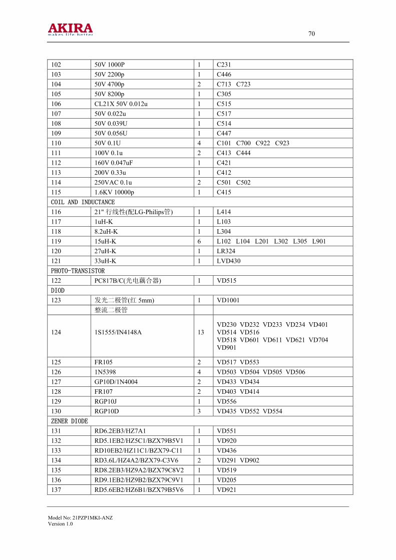
Model No: 21PZP1MKI-ANZVersion 1.0
102 50V 1000P 1 C231 103 50V 2200p 1 C446 104 50V 4700p 2 C713 C723 105 50V 8200p 1 C305 106 CL21X 50V 0.012u 1 C515 107 50V 0.022u 1 C517 108 50V 0.039U 1 C514 109 50V 0.056U 1 C447 110 50V 0.1U 4 C101 C700 C922 C923 111 100V 0.1u 2 C413 C444 112 160V 0.047uF 1 C421 113 200V 0.33u 1 C412 114 250VAC 0.1u 2 C501 C502 115 1.6KV 10000p 1 C415 COIL AND INDUCTANCE
116 21" 行线性(配LG-Philips管) 1 L414 117 1uH-K 1 L103 118 8.2uH-K 1 L304 119 15uH-K 6 L102 L104 L201 L302 L305 L901 120 27uH-K 1 LR324 121 33uH-K 1 LVD430 PHOTO-TRANSISTOR
122 PC817B/C(光电藕合器) 1 VD515 DIOD
123 发光二极管(红 5mm) 1 VD1001 整流二极管
124
1S1555/IN4148A
13
VD230 VD232 VD233 VD234 VD401 VD514 VD516 VD518 VD601 VD611 VD621 VD704 VD901
125 FR105 2 VD517 VD553 126 1N5398 4 VD503 VD504 VD505 VD506 127 GP10D/1N4004 2 VD433 VD434 128 FR107 2 VD403 VD414 129 RGP10J 1 VD556 130 RGP10D 3 VD435 VD552 VD554 ZENER DIODE
131 RD6.2EB3/HZ7A1 1 VD551 132 RD5.1EB2/HZ5C1/BZX79B5V1 1 VD920 133 RD10EB2/HZ11C1/BZX79-C11 1 VD436 134 RD3.6L/HZ4A2/BZX79-C3V6 2 VD291 VD902 135 RD8.2EB3/HZ9A2/BZX79C8V2 1 VD519 136 RD9.1EB2/HZ9B2/BZX79C9V1 1 VD205 137 RD5.6EB2/HZ6B1/BZX79B5V6 1 VD921
71
Model No: 21PZP1MKI-ANZVersion 1.0
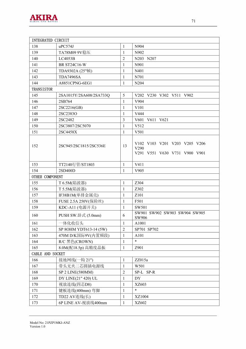
INTEGRATED CIRCUIT
138 uPC574J 1 N904 139 TA78M09 9V稳压 1 N902 140 LC4053B 2 N203 N207 141 BR ST24C16-W 1 N901 142 TDA9302A (25"帧) 1 N401 143 TDA7496SA 1 N701 144 A8851CPNG-6EG1 1 N204 TRANSISTOR
145 2SA1015Y/2SA608/2SA733Q 5 V202 V230 V302 V511 V902 146 2SB764 1 V904 147 2SC2216(GB) 1 V101 148 2SC2383O 1 V444 149 2SC2482 3 V601 V611 V621 150 2SC3807/2SC5070 1 V512 151 2SC4458X 1 V501
152
2SC945/2SC1815/2SC536E
13
V102 V103 V201 V203 V205 V206 V290 V291 V551 V630 V731 V900 V901
153 TT2140行管/ST1803 1 V411 154 2SD400D 1 V905 OTHER COMPONENT
155 T 6.5M(陷波器) 1 Z304 156 T 5.5M(陷波器) 1 Z302 157 IF38B1M(单排金属壳) 1 Z101 158 FUSE 2.5A 250V(保险丝) 1 F501 159 KDC-A11 (电源开关) 1 SW501
160 PUSH SW.卧式 (5.0mm) 6 SW901 SW902 SW903 SW904 SW905 SW906
161 一体化收信头 1 A1001 162 SP 8OHM YDT613-14 (5W) 2 SP701 SP702 163 470M D/K国际9V(内置频段) 1 A101 164 R/C 黑色(CROWN) 1 * 165 8.0M(配18.5p) 高精度晶振 1 Z901 CABLE AND SOCKET
166 接地网线(一钩 21") 1 ZZ015a 167 带头无夹二芯圆插电源线 1 W501 168 SP 2 LINE(580MM) 2 SP-L SP-R 169 DY LINE(21" 420) UL 1 DY 170 视放连线(四芯D8) 1 XZ603 171 键板连线(400mm) 弯脚 1 * 172 TD22 AV连线(长) 1 XZ1004 173 6P LINE AV-视放线400mm 1 XZ602

72
Model No: 21PZP1MKI-ANZVersion 1.0
174 CRT SOCKET(29"东芝)插拔 1 XZ601 175 S-VHS端子(D8) 1 XZ203 176 A/V SOCKET TX2-6ZA1 1 XZ201 177 单孔AV插座(红色)带开关 1 R 178 单孔AV插座(白色) 1 L 179 单孔AV插座(黄色) 1 V 180 AC SOCKET(2S 大型) 1 XZ501 181 SPEAKER SOCKET(小型二芯) 3 XZ701 XZ711 XZ904 182 2S SOCKET(中型) KEa 1 XZ504 183 3S SOCKET(小型) 2 XZ900 XZ901 184 DY SOCKET(中型) DYa 1 XZ411 185 5S SOCKET(小型) 1 XZ207 TRANSFORMER
186 LINE FILTER(电源滤波器) 1 L502 187 21"FBT高聚27KV视放帧24V 1 T402 188 21"变压器B+105V(同28) 1 T501 189 H-DRIVER(行推动) 1 T401

73
Model No: 21PZP1MKI-ANZ.Version 1.0
CIRCUIT DIAGRAM