Embed Size (px)
Citation preview

ALMA memo 455
Cartridge Test Cryostats for ALMA Front End
Yutaro Sekimoto∗, Toshiaki Kamba∗, Sozo Yokogawa∗†,Masahiro Sugimoto∗‡, Takeshi Okuda∗‡, Ryo Kandori∗†,
Ken’ichi Tatematsu∗, Kazuyuki Muraoka‡, Akitoshi Ueda∗,Tetsuo Nishino§, Norio Okada§, Takeo Fukuda§, Keiko Kaneko§,
Hideo Ogawa¶, Kimihiro Kimura¶, Kazufusa Noda‖,Katsuhiro Narasaki∗∗, Kazuji Suzuki††
April 18, 2003
Abstract
We have developed four cartridge test cryostats for ALMA FE cartridge-type re-ceiver with taking account of reliability and easy operation. It uses a simple, compactand efficient thermal link between a cartridge-type receiver and a plate connected toa 3 stage Gifford-Mcmahon (GM) cryocooler. The cooling time of the cartridge-typereceiver is less than 10 hours. With a cartridge loader, a cartridge-type receiver iseasily inserted and extracted in a condition that the cryostat is closed.
∗ALMA project office, National Astronomical Observatory of Japan, 2-21-1 Osawa Mitaka Tokyo 181-
8588, Japan†The Graduate University for Advanced Studies, Japan‡Insititute of Astronomy, University of Tokyo, 2-21-1 Osawa Mitaka Tokyo 181-0015, Japan§Advanced Technology Center, National Astronomical Observatory of Japan, 2-21-1 Osawa Mitaka
Tokyo 181-8588, Japan¶Department of Earth and Life Sciences, College of Integrated Arts and Sciences,
Osaka Prefecture University, 1-1 Gakuen-cho Sakai Osaka 599-8531, Japan‖Oshima Prototype Engineering Co., ltd., 3-10-28 Nishikubo Musashino Tokyo 180-0013, Japan∗∗Sumitomo Heavy Industries, ltd., 5-2 Soubiraki-cho Niihama Ehime 792-8588, Japan††The Instrument Development Center of School of Science, Nagoya University, Japan
1

1 Introduction
The ALMA requires production of a large number of the state-of-art SIS receivers. To pro-duce and operate several hundred receivers, a concept of modular receiver corresponding tofrequency bands is adopted for ALMA [1]. The module called as a cartridge-type receiveris equipped with all components as cooled optics, SIS mixers, IF amplifiers, and LO. Thenit works as designed under cooled condition. To realize the modular concept, automaticthermal link has been proposed [2]. A concept of cartridge-type receiver has a clear andcompatible interface, and thus the band cartridges can be developed independently byworldwide front end engineers.
NAOJ and universities in Japan planed the Large Millimeter Submillimeter Array(LMSA) [3]. A submillimeter antenna with 10 m diameter was constructed as a prototypeone of LMSA [4]. It has been installed at Pampa la Bola (Alt. 4800m) in the northern Chileas one of research activities of LMSA, which is called Atacama Submillimeter TelescopeExperiment [5]. For this telescope, an ALMA cartridge-type cryostat with three cartridgebays has developed [6]. To accommodate cartridge-type receivers, we have developed asimple thermal link which makes it possible to plug-in them [7]. We have evaluated withengineering models of Band 3, 8 and 10 cartridges on the site in the northern Chile [8].
To support developments of state-of-art cartridge-type receivers, we have fabricatedcartridge test cryostats by modifying the ALMA cartridge-type cryostat. To design it,we counted reliability, short cooling time and easy handling. A cartridge loader is alsofabricated for easy handling of cartridge-type receiver.
2 Instrumentation
2.1 Cryostat
The cryostat is designed to be as small as possible for easy handling and short coolingtime. A cylindrical cryostat has a dimension of 460 mm diameter and 600 mm heighthouses a cartridge-type receiver of 170 mm or 140 mm diameter as shown in Figure 1.The cryostat is cooled by a 3 stage GM cryocooler (Sumitomo RDK 3ST). In this cryostat,temperature of 4 K is used for SIS mixers and optical components such as mirrors, feedhorns, a local oscillator (LO) coupler, and polarization grids. Low noise amplifiers arecooled on the 12 K stage. Temperature of 80 K is used for radiation shield and cooledLOs.
A cross-section of the cryostat is shown in Figure 2. The sidewall of the vacuum vessel( 1©) is made of SUS304 with 4 mm thickness. The inner surface of the sidewall is polishedto reduce the emissivity. The top and bottom flanges ( 2©, 3©) of the vacuum vessel aremade of Al6061-T6 to reduce the weight.
The 4 K ( 7©) and 12 K ( 6©) plates connected to the cold head are made of oxygenfree copper (C1050) of 6 mm thickness with gold plated. The 80 K plate ( 5©) is made
2
Figure 1: Schematic drawing of the cartridge test cryostat. There are three plates of 4 K,12 K, and 80 K from up to down.
3

of Al6061 with 6 mm thickness to reduce the weight. These plates are supported by 3columns of GFRP with 46 mm in diameter and 2 mm thickness.
The 12 K and 80 K radiation shields (11©, 13©) are made of 2 mm thick copper withNi-plated. No multi-layer insulator is used.
2.2 Cartridge
The interface of the receiver cartridges for the ALMA was proposed by the RAL [2]. Acartridge has 3 disk-like stages, the diameter of which is 169.0 mm at the 4 K stage,169.5 mm at the 12 K stage, and 170 mm at the 80 K stage. A cartridge proposed by theRAL is supported by the outer shell (closed-type). Although the closed-type cartridge isstronger against gravitational deformation, decomposition of the cartridge is indispensableto assemble receivers.
A column-type cartridge we have developed can be assembled without any decomposi-tion of the cartridge (Figure 3). The support structure is a column of 90 mm in diameterand 4 mm in thickness made of GFRP. To reduce thermal radiation on the structure,the GFRP pipes are gold plated. The outer space of this support structure is used forinstallation of the equipments such as LNAs.
Because the optics which couples between subreflector and the feed horn is installed onthe 4 K stage of the cartridge, the alignment of the 4 K stage is important. The alignmentof a cartridge including the 4 K stage is defined by the bottom plate. The 4 K stage ismachined after the structure is assembled so that the tilt to the bottom plate is fabricatedto be less than 0.6 mrad. The tolerance between the center of the bottom plate and thatof the 4 K stage is less than 50 µm. The structure has enough strength for gravitationdeformation due to elevation motion of an astronomical telescope and thermal contractionof the plates.
There are two D-type connectors with 37 pins on the bottom plate. There are twoports for waveguide flange or photo connectors on the bottom plate.
2.3 Thermal link
We have developed a simple, small, and efficient thermal link, which is applied at varioustemperatures ranging from 2 K to 100 K [7]. The concept of automatic thermal link wasfirst proposed by the Rutherford Appleton Laboratory (RAL) for use in ALMA receivers[2]. Their thermal link was made using flexible braids without screws. However, it isslightly large and complicated.
A thermal conduction is achieved with the thermal link which clamps the cartridgewith an external force of a metal spring or nylon. The link is composed of a ring-likestructure and a clamp as shown in Figure 4. The link is the same for all 3 stages exceptfor the inner diameter. These links can be fabricated at relatively low cost.
The link requires small space with an extra width of 12.5 mm for a cartridge, and this
4

Figure 2: A cross-sectional view of the cartridge-type cryostat. The cryostat is composedof 3 stages, 4 K, 12 K, and 80 K from up to own. The parts number is indicated.
5

Figure 3: A schematic drawing of the cartridge structure.
6

Figure 4: (a) A photograph of the thermal link. (b) Cross-sectional view of the thermallink. The link is composed of a crown-like ring made of oxygen free copper and clampbelt made of nylon. The crown-like rings divided to 120 pieces. (c) Up side view of thethermal link.
thermal link makes the cryostat compact. This link weighs about 250 g. The contactingpart of the ring is divided to 120 pieces, like comb. The thin part of the ring is alsodivided, so that this link is flexible to avoid thermal deformation of the plates.
The clamping part is a metal spring or nylon ring. The thermal shrinkage of the nylonis much larger than that of the copper, and the nylon ring shrinks and ties up the copperring under the low temperature condition. The nylon is the slightly larger diameter forclamp the inner copper ring. The nylon ring is the same as RAL’s link, which enables thelink to clamp with ∼2000 N at 4 K [2].
2.4 Coldhead interface
To reduce the mechanical vibration of the cartridge, an interface between the coldheadand the 4 K plate has been developed (Figure 5). This flexible part is made of high puritycopper cables (99.9999 %), which is fabricated for audio speakerphones. These cables aresoldered to OFCu with Ag paste.
The connection between the cryocooler and the 12 K, 80 K plates has bellows-likestructure (25©, 26©) as shown in Figure 2 to reduce mechanical vibration of the cryocooler.
2.5 Cartridge Loader
A cartridge loader which enables a cartridge insert and extract from the cryostat hasdeveloped. It consists 4 poles with ball bearings made by THK Co. to guide the cartridge-type receiver as shown in Figure 6. With this loader, the cartridge is smoothly insertedand extracted in a condition that the cryostat is closed.
7

Figure 5: A coldhead interface to reduce the mechanical vibration
2.6 Interface
Vacuum interfaces are provided on the bottom plate as shown in figure 7. There are fourports for evacuation (DN 40 flange), monitor (DN 25 and DN 16 flanges) and ventilation(DN 10 flange).
There are two D-type connectors with 25 pins on the bottom plate. Temp sensorsand heaters are cabled from 25 pin D-type connectors. There are two ports for waveguideflange or photo connectors on the bottom plate.
On the top plate, there is an interface plate of 170 m diameter ( 3©). Cartridge devel-opers can modify the position and the size of the vacuum window for their cartridge-typereceiver. The IR filters also can be changed with interface plates of 170 mm diameter ofthe 80 K and 12 K radiation shields (22©).
There is a window on the sidewall (29©). This window is used for displacement mea-surements by a laser or LO injection for submillimeter receivers [6]. This LO windowis useful for quasi-optical coupling of conventional LO for bands 8, 9, and 10, which hasmechanical tuners.
A frame for this cryostat is constructed with commercial Al rods. The size of thebottom unit is 600 in width, 600 in depth, and 700 mm in height.
2.7 Assembly
The three plates are assembled with a cylinder of 190 mm diameter instead of the cartridgefor alignment. Between the parts, Apiezon Greece is used for conduction.
There are positioning holes on the bottom and top vacuum plates for alignment.
8

Figure 6: The cartridge loader
9
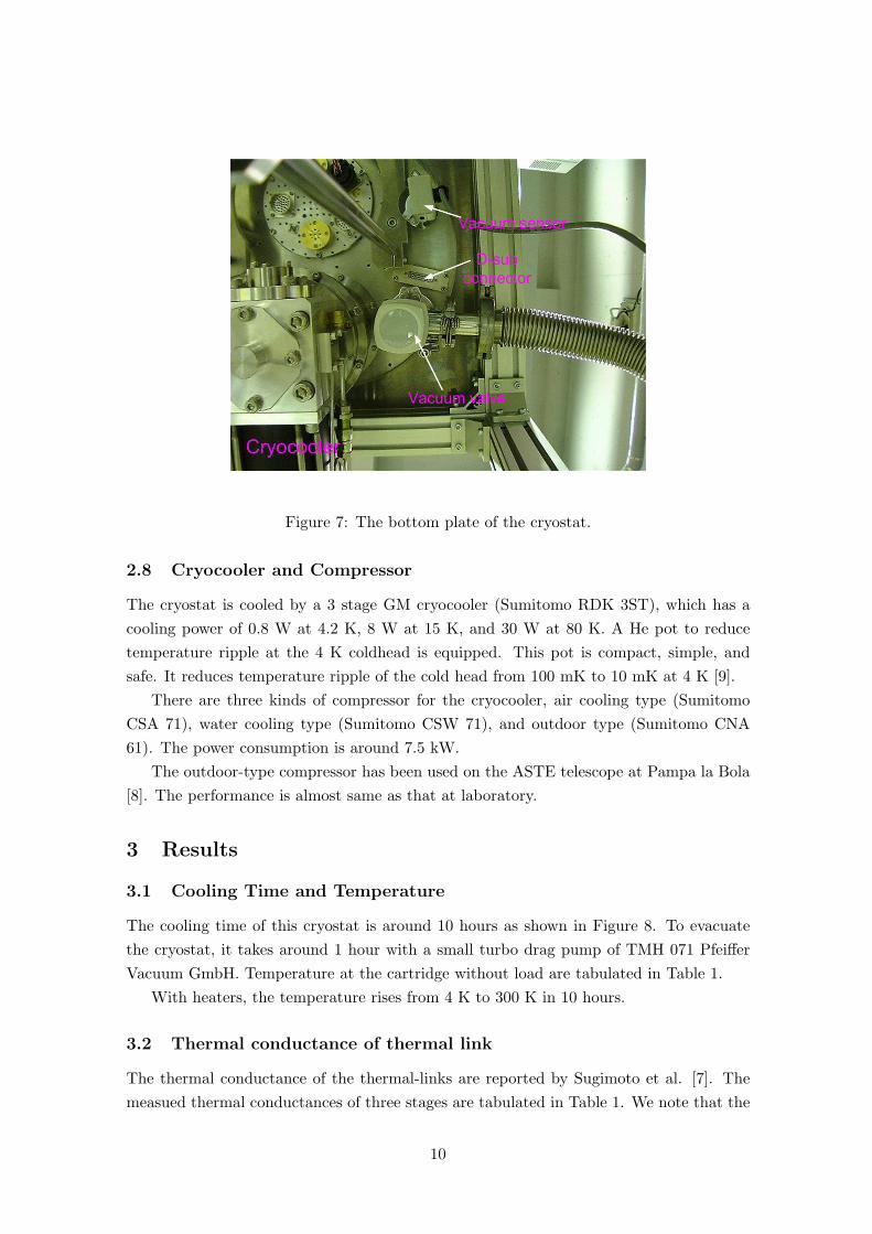
Figure 7: The bottom plate of the cryostat.
2.8 Cryocooler and Compressor
The cryostat is cooled by a 3 stage GM cryocooler (Sumitomo RDK 3ST), which has acooling power of 0.8 W at 4.2 K, 8 W at 15 K, and 30 W at 80 K. A He pot to reducetemperature ripple at the 4 K coldhead is equipped. This pot is compact, simple, andsafe. It reduces temperature ripple of the cold head from 100 mK to 10 mK at 4 K [9].
There are three kinds of compressor for the cryocooler, air cooling type (SumitomoCSA 71), water cooling type (Sumitomo CSW 71), and outdoor type (Sumitomo CNA61). The power consumption is around 7.5 kW.
The outdoor-type compressor has been used on the ASTE telescope at Pampa la Bola[8]. The performance is almost same as that at laboratory.
3 Results
3.1 Cooling Time and Temperature
The cooling time of this cryostat is around 10 hours as shown in Figure 8. To evacuatethe cryostat, it takes around 1 hour with a small turbo drag pump of TMH 071 PfeifferVacuum GmbH. Temperature at the cartridge without load are tabulated in Table 1.
With heaters, the temperature rises from 4 K to 300 K in 10 hours.
3.2 Thermal conductance of thermal link
The thermal conductance of the thermal-links are reported by Sugimoto et al. [7]. Themeasued thermal conductances of three stages are tabulated in Table 1. We note that the
10

Figure 8: Cooling time of a cartridge-type cryostat.
11

Table 1: summary of results
No1 No2 No3 No4Cartridge diameter 170 mm 170 mm 170 mm 140 mm
Cartridge-type NAOJ RAL NAOJ RAL NAOJ RAL NAOJTemperature [K] [K] [K] [K] [K] [K] [K]
4K stage 2.91 2.80 2.98 3.18 3.29 3.25 3.0612K stage 12.33 12.75 10.48 8.82 13.26 12.61 10.8780K stage 59.08 58.86 53.41 52.19 74.11 73.29 68.36
Conductance [W/K] [W/K] [W/K] [W/K] [W/K] [W/K] [W/K]4K stage 1.1 1.0 1.0 4.2 1.0 2.0 2.0
12K stage 2.9 2.3 2.2 1.7 1.6 1.3 1.780K stage 5.4 6.5 3.5 8.6 5.2 4.2 4.0Vibration [µm] [µm] [µm] [µm] [µm]horizontal 7 ∼ 9 10 ∼ 12 6 6
Vacuum [torr] [torr] [torr] [torr] [torr] [torr] [torr]room temp 4.2× 10⁻⁴ - - 8.7× 10⁻⁵ 1.5× 10⁻³
cooled state - - 4.5× 10⁻⁷ - 1.8× 10⁻⁷
Cooling time [hour] [hour] [hour] [hour] [hour] [hour] [hour]10 10 10 10 10 10 10
thermal conductances of RAL’s cartridges are consistent with that of NAOJ’s cartridges.
3.3 Temperature ripple
Temperature ripple associated with cryocooler motions is reduced with a He pot attachedon the 3rd stage of the cold head. The ripples at the cartridge, plate and bellows are 4, 7,and 12 mK, respectively (Figures 9, 10). The dependence is related to the distance fromthe coldhead. If some amount of heat capacitance as optics is put on the 4 K stage, theripple will be reduced further [9].
3.4 Mechanical vibration
Mechanical vibration with respect to vertical on the 4 K stage of the cartridge was mea-sured with a laser displacement system. The vibration is 3 µm peak-to-peak as shown inFigure 11. The displacement of coldhead of 30 µm peak-to-peak [9] is reduced by orderof magnitude. Because the cartridge structure is so strong, the vibration may be due tothat of the bottom plate.
Horizontal mechanical vibration on the 4 K stage of the cartridge also was measured asshown in Figure 12 and Table 1. It is larger than the vertical vibration. Vertical vibrationof the cryocooler is transformed to horizontal one due to the structure of this cryostat.
12

2.49
2.51
2.53
2.55
2.57
2.59
2.61
2.63
0.00 5.00 10.00 15.00 20.00
Time [sec]
Te
mp
era
ture
[K
] He pot 12 mK p-p
4 K Cartridge 4 mK p-p
4K Plate 7 mK p-p
Figure 9: The temperature variation on the 4 K stage and plate in 20 seconds. The rippleis associated with the cold head displacement of 3 stage GM cryocooler.
8.85
8.9
8.95
9
9.05
9.1
9.15
0.00 5.00 10.00 15.00 20.00
Time [sec]
Tem
pera
ture
[K
]
12 K plate (0.15 K p-p)
12 K cartridge (0.1 K p-p)
Figure 10: The temperature variation on the 12 K stage and plate in 20 seconds. Theripple is associated with the cold head displacement of 3 stage GM cryocooler.
13

Figure 11: The vertical vibration on the 4 K stage of the cartridge.
Figure 12: The horizontal vibration on the 4 K stage of the cartridge.
The amplitude of 8µm is reasonably small compared with the submillimeter wavelength(> 350µm).
4 Conclusion
Design and performance of cartridge test cryostats are presented. We have developedengineering models of Band 10, band 8, and Band 3 cartridges with this cartridge-testcryostat[8]. This cryostat was used for noise measurements of hybrid photonic LO at 500GHz [10]. The cryostats were reliable over a year. We hope that these cryostats are usefulfor developing cartridge-type receivers.
14
Acknowledgements
We would like to thank Mark Harman, Anna Orlowska, Brian Ellison, Wolfgang Wild,Charles Cunningham, Toshimi Sato, Youichiro Ikeya for many technical technical sugges-tions. We also thank Richard Wade, Tetsuo Hasegawa、Kurazo Chiba, Takashi Noguchi,Junji Inatani, Hiroyuki Iwashita, Masato Ishiguro, Ryohei Kawabe, Satoru Iguchi, KotaroKohno, Norikazu Mizuno for various supports.
References
[1] ALMA project book version 5.5 2002 Chapter 5, ALMA Front Ends inhttp://www.alma.nrao.edu/
[2] ALMA project book version 5.5 2002 Chapter 6, Receiver Cryogenic System inhttp://www.alma.nrao.edu/
[3] M. Ishiguro and LMSA Working Group 1998, in Advanced Technology MMW, Radio, Tera-hertz Telescopes, ed. T. G. Phillips, Proceedings of SPIE Vol. 3357, 244
[4] N. Ukita, et al., 2001, SPIE 4015: NRO 10-m sublmillimeter telescope, 177
[5] Y. Sekimoto, & LMSA Working Group 2001a, ASP Conf. Ser. 235: Science with the AtacamaLarge Millimeter Array, 245
[6] S. Yokogawa, Y. Sekimoto, M. Sugimoto, et al. 2003 PASJ in press, ”Plug-In CryogenicSystem for Cartridge-Type SIS Receivers”
[7] M. Sugimoto, Y. Sekimoto, S. Yokogawa, et al. 2003a Cryogenics, in press ”Thermal Link forCartridge-type Cryostat”
[8] M. Sugimoto, Y. Sekimoto, et al. 2003b in preparation
[9] Y. Sekimoto, T. Sakai, G. Saito, K. Tatematsu, K. Tanaka, K. Kohno, T. Noguchi, H.Iwashita, et al. 2001b, PASJ, 53, 951
[10] Y. Sekimoto, A. Ueda, T. Okuda, E. Bryerton, M. Sugimoto, H. Matsuo, S. Yokogawa, T.Noguchi, M. Ishiguro, H. Ito, T. Nagatsuma, A. Hirata, and J. M. Payne. 2003 ALMA memo449“ Noise Evaluation of Hybrid Photonic Local Oscillator at 500 GHz”
15