Embed Size (px)
Citation preview
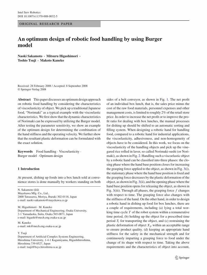
Intel Serv RoboticsDOI 10.1007/s11370-008-0032-5
ORIGINAL RESEARCH PAPER
An optimum design of robotic food handling by using Burgermodel
Naoki Sakamoto · Mitsuru Higashimori ·Toshio Tsuji · Makoto Kaneko
Received: 28 February 2008 / Accepted: 8 September 2008© Springer-Verlag 2008
Abstract This paper discusses an optimum design approachon robotic food handling by considering the characteristicsof viscoelasticity of object. We pick up a traditional Japanesefood, “Norimaki” as a typical example with the viscoelasticcharacteristics. We first show that the dynamic characteristicsof Norimaki can be expressed by utilizing the Burger model.After testing the parameter sensitivity, we show an exampleof the optimum design for determining the combination ofthe hand stiffness and the operating velocity. We further showthat the resultant plastic deformation can be formulated withthe exact solution.
Keywords Food handling · Viscoelasticity ·Burger model · Optimum design
1 Introduction
At present, dishing up foods into a box lunch sold at conve-nience stores is done manually by workers standing on both
N. Sakamoto (B)Mayekawa Mfg. Co., Ltd.,2000 Tatsusawa, Moriya, Ibaraki 302-0118, Japane-mail: [email protected]
M. Higashimori · M. KanekoDepartment of Mechanical Engineering, Osaka University,2-1 Yamadaoka, Suita, Osaka 565-0871, Japane-mail: [email protected]
M. Kanekoe-mail: [email protected]
T. TsujiDepartment of Artificial Complex Systems Engineering,Hiroshima University, 1-4-1 Kagamiyama, Higashihiroshima,Hiroshima 739-8527, Japane-mail: [email protected]
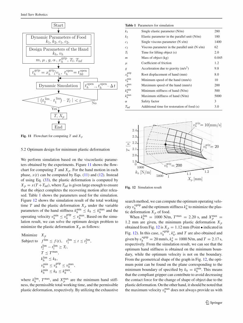
sides of a belt conveyor, as shown in Fig. 1. The net profitof an individual box lunch, that is, the sales price minus thecost of the raw food materials, personnel expenses and othermanagement costs, is limited to roughly 2% of the retail storeprice. In order to increase the net profit or to improve the pro-fit ratio for dealing with box lunches, the manual processesfor dishing up should be shifted to an automatic sorting andfilling system. When designing a robotic hand for handlingfood, compared to a robotic hand for industrial applications,the viscoelasticity, adhesiveness, and non-homogeneity ofobjects have to be considered. In this work, we focus on theviscoelasticity of the handling objects and pick up the vine-gared rice rolled in laver, so called Norimaki-sushi (or Nori-maki), as shown in Fig. 2. Handling such a viscoelastic objectby a robotic hand can be classified into three phases: the clo-sing phase where the hand base position closes for increasingthe grasping force applied to the object, as shown in Fig. 3(i),the stationary phase where the hand base position is fixed andthe grasping force decreases by the plastic deformation of theobject, as shown in Fig. 3(ii), and the opening phase where thehand base position opens for releasing the object, as shown inFig. 3(iii). Through all phases, the grasping force f changeswith respect to time. The grasping force also changes withthe stiffness of the hand. On the other hand, in order to designa robotic hand in dishing up food for box lunches, there area couple of requirements, including (a) lying a total wor-king time cycle T of the robot system within a remunerativetime period, (b) holding up the object for a prescribed timeperiod Tl for transporting the object, and (c) restraining theplastic deformation of object X p within an acceptable rangeto ensure product quality. (d) keeping an appropriate handstiffness for the safety in the mechanical strength and forcontinuously imparting a grasping force to food under thechange of its shape with respect to time. Taking the aboverequirements and the characteristics of object into account,
123
Intel Serv Robotics
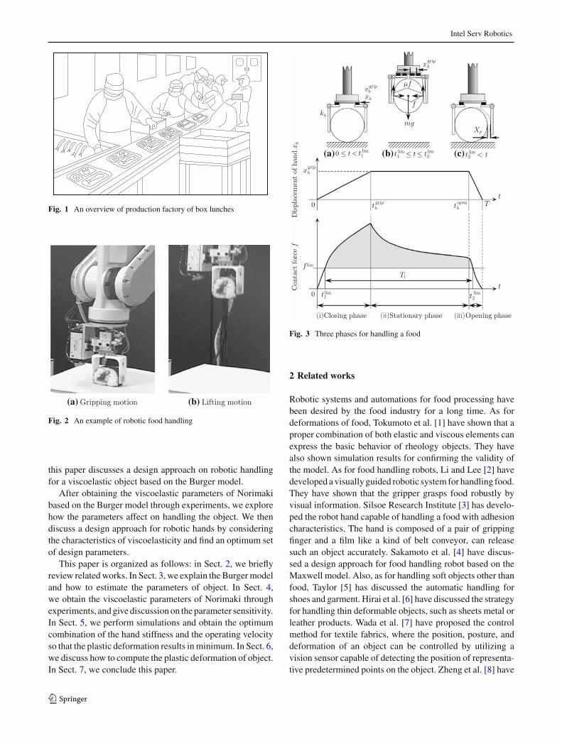
Fig. 1 An overview of production factory of box lunches
(a) (b)
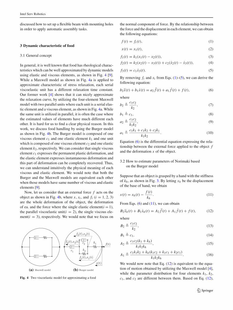
Fig. 2 An example of robotic food handling
this paper discusses a design approach on robotic handlingfor a viscoelastic object based on the Burger model.
After obtaining the viscoelastic parameters of Norimakibased on the Burger model through experiments, we explorehow the parameters affect on handling the object. We thendiscuss a design approach for robotic hands by consideringthe characteristics of viscoelasticity and find an optimum setof design parameters.
This paper is organized as follows: in Sect. 2, we brieflyreview related works. In Sect. 3, we explain the Burger modeland how to estimate the parameters of object. In Sect. 4,we obtain the viscoelastic parameters of Norimaki throughexperiments, and give discussion on the parameter sensitivity.In Sect. 5, we perform simulations and obtain the optimumcombination of the hand stiffness and the operating velocityso that the plastic deformation results in minimum. In Sect. 6,we discuss how to compute the plastic deformation of object.In Sect. 7, we conclude this paper.
(a) (b) (c)
Fig. 3 Three phases for handling a food
2 Related works
Robotic systems and automations for food processing havebeen desired by the food industry for a long time. As fordeformations of food, Tokumoto et al. [1] have shown that aproper combination of both elastic and viscous elements canexpress the basic behavior of rheology objects. They havealso shown simulation results for confirming the validity ofthe model. As for food handling robots, Li and Lee [2] havedeveloped a visually guided robotic system for handling food.They have shown that the gripper grasps food robustly byvisual information. Silsoe Research Institute [3] has develo-ped the robot hand capable of handling a food with adhesioncharacteristics. The hand is composed of a pair of grippingfinger and a film like a kind of belt conveyor, can releasesuch an object accurately. Sakamoto et al. [4] have discus-sed a design approach for food handling robot based on theMaxwell model. Also, as for handling soft objects other thanfood, Taylor [5] has discussed the automatic handling forshoes and garment. Hirai et al. [6] have discussed the strategyfor handling thin deformable objects, such as sheets metal orleather products. Wada et al. [7] have proposed the controlmethod for textile fabrics, where the position, posture, anddeformation of an object can be controlled by utilizing avision sensor capable of detecting the position of representa-tive predetermined points on the object. Zheng et al. [8] have
123
Intel Serv Robotics
discussed how to set up a flexible beam with mounting holesin order to apply automatic assembly tasks.
3 Dynamic characteristic of food
3.1 General concept
In general, it is well known that food has rheological charac-teristics which can be well approximated by dynamic modelsusing elastic and viscous elements, as shown in Fig. 4 [9].While a Maxwell model as shown in Fig. 4a is applied toapproximate characteristic of stress relaxation, each serialviscoelastic unit has a different relaxation time constant.Our former work [4] shows that it can nicely approximatethe relaxation curve, by utilizing the four-element Maxwellmodel with two parallel units where each unit is a serial elas-tic element and a viscous element, as shown in Fig. 4a. Whilethe same unit is utilized in parallel, it is often the case wherethe estimated values of elements have much different eachother. It is hard for us to find a clear physical reason. In thiswork, we discuss food handling by using the Burger modelas shown in Fig. 4b. The Burger model is composed of oneviscous element c1 and one elastic element k1 and one unitwhich is composed of one viscous element c2 and one elasticelement k2, respectively. We can consider that single viscouselement c1 expresses the permanent plastic deformation, andthe elastic element expresses instantaneous deformation andthis part of deformation can be completely recovered. Thus,we can understand intuitively the physical meaning of eachviscous and elastic element. We would note that both theBurger and the Maxwell models are equivalent each otherwhen those models have same number of viscous and elasticelements [9].
Now, let us consider that an external force f acts on theobject as shown in Fig. 4b, where x , xi , and fi (i = 1, 2, 3)are the whole deformation of the object, the deformationof ea. and the force where the single elastic element(i = 1),the parallel viscoelastic unit(i = 2), the single viscous ele-ment(i = 3), respectively. We would note that we focus on
(a) (b)
Fig. 4 Two viscoelastic model for approximating a food
the normal component of force. By the relationship betweenthe force and the displacement in each element, we can obtainthe following equations:
f (t) = fi (t), (1)
x(t) = x1(t), (2)
f1(t) = k1(x1(t) − x2(t)), (3)
f2(t) = k2(x2(t) − x3(t)) + c2(x2(t) − x3(t)), (4)
f3(t) = c1 x3(t). (5)
By removing fi and xi from Eqs. (1)–(5), we can derive thefollowing equation:
b2 x(t) + b1 x(t) = a2 f (t) + a1 f (t) + f (t), (6)
where
b2 � c1c2
k2, (7)
b1 � c1, (8)
a2 � c1c2
k1k2, (9)
a1 � c1k1 + c1k2 + c2k1
k1k2. (10)
Equation (6) is the differential equation expressing the rela-tionship between the external force applied to the object fand the deformation x of the object.
3.2 How to estimate parameters of Norimaki basedon the Burger model
Suppose that an object is grasped by a hand with the stiffnessof kh , as shown in Fig. 3. By letting xh be the displacementof the base of hand, we obtain
x(t) = xh(t) − f (t)
kh. (11)
From Eqs. (6) and (11), we can obtain
B2 xh(t) + B1 xh(t) = A2 f (t) + A1 f (t) + f (t), (12)
where
B2 � c1c2
k2, (13)
B1 � c1, (14)
A2 � c1c2(k1 + kh)
k1k2kh, (15)
A1 � c1k1k2 + kh(k1c2 + k1c1 + k2c1)
k1k2kh. (16)
We would now note that Eq. (12) is equivalent to the equa-tion of motion obtained by utilizing the Maxwell model [4],while the parameter distribution for four elements k1, k2,c1, and c2 are different between them. Based on Eq. (12),
123

Intel Serv Robotics
we can compute the viscoelastic parameters ci and ki ofNorimaki from experimental results. Now, suppose that thehand makes contact with the object. The contact force is zeroat the initial phase (t = 0, xh = 0). We further suppose thatthe commands for open and close to the hand are given in thefollowing procedure:
1. Closing phase (0 ≤ t < tgriph ). Close the hand until the
position of xh results in xgriph with the operating velocity
of vgriph (= xh), as shown in Fig. 3(i).
2. Stationary phase (tgriph ≤ t < topen
h ). Fix the hand at
xh = xgriph , as shown in Fig. 3(ii).
3. Opening phase (topenh ≤ t ≤ T ). Open the hand until the
position of xh results in zero with the operating velocityof v
openh , as shown in Fig. 3(iii).
By inserting the measured xh(t) and f (t) into Eq. (12), wecan compute A1, A2, B1, and B2. In order to avoid a largeerror induced by differentiating the noisy signal, instead ofusing Eq. (12), we transform Eq. (12) to the following inte-gration equation:
M p = q, (17)
where
M �
⎡⎢⎢⎢⎢⎢⎣
− f (t1), − ∫f (t1)dt, xh(t1),
∫xh(t1)dt
− f (t2), − ∫f (t2)dt, xh(t2),
∫xh(t2)dt
......
......
− f (tn), − ∫f (tn)dt, xh(tn),
∫xh(tn)dt
⎤⎥⎥⎥⎥⎥⎦
(18)
p � [A2, A1, B2, B1]T , (19)
q �[∫∫
f (t1)dt2,
∫∫f (t2)dt2, . . . ,
∫∫f (tn)dt2
](20)
f (ti ) and xh(ti ) are the contact force and the base displa-cement of hand, respectively, at the sampling time ti (i =1, 2, . . . , n). From Eq. (17), we can estimate p by the least-square method as follows:
p = (MT M)−1 MT q. (21)
After computing p by using experimental data, the viscoe-lastic parameters ci and ki (i = 1, 2) can be computed fromEqs. (13)–(16), as follows:
k1 = B2kh
A2kh − B2, (22)
k2 = B12 B2
A1 B1 B2 − A2 B12 − B2
2 , (23)
c1 = B1, (24)
c2 = B1 B22
A1 B1 B2 − A2 B12 − B2
2 . (25)
Fig. 5 Experimental system
We would note that k1 results in B2/A2 when kh is largeenough.
4 Experiments
4.1 Experimental system
Figure 5 gives an overview of the experimental system, wherea dummy hand with two parallel grippers with the stiffnessof kh is utilized. One gripper is fixed on the base and theother can be moved by a linear slider, so that they can realizesmooth opening and closing motions. The base displacementof the gripper xh(t) is measured by the encoder integrated inthe motor for driving the slider. The normal component ofcontact force f (t) is measured by the strain gauge attachedto the gripper.
4.2 Experimental result
We adopt a popular Norimaki as an object for the experiment,where the hand stiffness kh , the operating velocity in closingphase v
griph , the operating velocity in opening phase v
openh ,
the base displacement xgriph , the time for finishing the closing
motion is tgriph , and the time for starting the opening motion
is topenh are 8500 N/m, 20 mm/s, 20 mm/s, 8 mm, 0.8 s, and
5.0 s, respectively. The continuous line in Fig. 6 shows thecontact force between the hand and the object with respectto time. From this line, we can see that the contact forceincreases in the closing phase (0 ≤ t < 0.8 s), the contactforce relaxes in the stationary phase (0.8 ≤ t < 5.0 [s]),and the contact force rapidly decreases in the opening phase(5.0 ≤ t ≤ 5.5 s), respectively.
4.2.1 Parameter estimation
The viscoelastic parameters ci and ki are estimated by usingthe contact force data in Fig. 6, are indicated as well inFig. 6, where the dashed line in Fig. 6 shows the reprodu-ced contact force computed by using Eqs. (12)–(16) with
123

Intel Serv Robotics
Fig. 6 The output of f (t) with respect to time
Fig. 7 The output of f (t) with respect to time under various xgriph
the estimated parameters ki , ci and the hand position dataxh(t), respectively. We can see that the reproduced contactforce nicely matches with that obtained by the experiment,where the degree of approximation is given by R2 = 0.99.In order to obtain the average parameters of Norimaki, weexecute experiments for three different base displacementsxgrip
h = {4, 8, 12} mm, and performed ten times estima-tions for each displacement. In Fig. 7, we show the ave-rage of estimated viscoelastic parameters. The continuousline and the dashed line in Fig. 7 show one of the experimen-tal contact force and the reproduced contact force, respecti-vely, for xgrip
h = {4, 8, 12} mm. The average of parametersin Fig. 7 are utilized for the analysis in Sect. 5.
Fig. 8 The simulation results under the change of parameter c1
Fig. 9 The simulation results under change of parameter c2
4.2.2 Parameter sensitivity
From Fig. 6, we can see that the viscous element c1 is extre-mely lager than c2. Let us now examine the parametersensitivity in the Burger model. In order to examine howeach viscous parameter affect on the three handling phases,we compute the contact force when the viscous parametersc1 and c2 are changed. Figures 8 and 9 show the compu-ted contact forces, where the viscous elements c1 and c2 areset by ten or one over ten times of the estimated parameter,respectively. From Fig. 8, we can see that under the viscousparameter c1 with ten times more than the original one, theforce relaxation arises in only initial part of the stationaryphase, and the force is then keeps nearly constant till the ope-ning motion. Under the c1 with one over ten of the originalone, the contact force decreases drastically after the closingphase. Based on these observations, the viscous element c1
123

Intel Serv Robotics
Fig. 10 The effect of time after the objects are produced
mainly controls the contact force in the stationary phase, andthis parameter concerns with keeping the grasp of the objectwhile the hand lifts up the object. From Fig. 9, we can see thatthe viscous element c2 is important to generate the contactforce in the closing phase, and this parameter is concernedwith the initial increase of force during the phase. Figure 10shows how the contact force is affected by the time after theobjects are produced, where (a), (b) and (c) show results byusing objects one, two and twenty four hours after they areproduced, respectively. From Fig. 10, we can see that thecontact force generally increase as the time after productionincreases, while the additional increase under twenty fourhours after production is only 20% of that under two hoursafter production. From Fig. 10, we neglect the time depen-dency of parameters of Norimaki after two hours have passed.From these discussions, while dynamic parameters changedepending upon foods. Once foods are fixed in the lunch boxfactory, their dynamic parameters change little for a flow ofsame foods. Therefore, the parameter estimation itself is notso sensitive to the solution of the optimum problem we arehandling in the next chapter.
5 Optimum design
In this section, we consider the optimum design, where weregard both the hand stiffness kh and the operating velocityv
griph and v
openh as the design parameters of the hand.
5.1 Definition of plastic deformation and total working time
For a given set of the base displacement of the hand in thestationary phase xgrip
h and the operating velocity in the closing
phase vgriph , the time for finishing the closing phase tgrip
h is
determined as follows:
tgriph =
∣∣∣∣∣xgrip
h
vgriph
∣∣∣∣∣ . (26)
On the other hand, the time for starting the opening phasetopenh has to be determined according to the transporting time
Tl . Suppose that the transporting time Tl is given. For avoi-ding that the hand drops the object, the following conditionfor normal component of the contact force is required:
mgα ≤ 2µ f, (27)
where m, g, µ, and α are the mass of object, the gravitationalacceleration, the friction coefficient between the hand and theobject, and the safety factor,1 respectively. From Eq. (27), wecan express the limitation of contact force as follows:
f lim � mgα
2µ. (28)
Suppose that in the closing and the opening phases, there areunique times at which f (t) = f lim, as shown in Fig. 3. Sucht lim1 and t lim
2 are defined by the following conditions:
t lim1 � t | f = f lim (0 ≤ t lim
1 ≤ tgriph ), (29)
t lim2 � t | f = f lim (topen
h ≤ t lim2 ≤ T ). (30)
To guarantee that the hand can support the object for the timeTl of the transport of object, the following condition is furtherrequired:
t lim2 − t lim
1 ≥ Tl , (31)
topenh is determined in the following. First, we assume the
initial time for starting the opening phase topenh0 = t lim
1 + Tl .Then, we solve the dynamic behavior of the object by usingthe simulation tool (MSC. ADAMS). Since the solutionincludes the force pattern f (t) with respect to time t , wecan obtain t lim
1 and t lim2 . However, the computed t lim
1 and t lim2
are not satisfied with the relationship t lim2 − t lim
1 = Tl in
general. In the next step, we change topenh to topen
h − �t until|t lim
2 − t lim1 − Tl | < ε where ε is a small positive value. This
process is given in Fig. 11 showing the flowchart. Under theabove tgrip
h and topenh , we define the total working time T and
the plastic deformation X p as follows:
T � topenh +
∣∣∣∣∣xgrip
h
vmaxh
∣∣∣∣∣ , (32)
X p � x(∞), (33)
where the hand opens with the maximum velocity vmaxh in
the opening phase, for simplicity.
1 α ≥ 1 indicates how much larger the friction force is required to bethan the gravity force applied to the object. However, an excessivelylarge α leads to a large contact force, and as a result, to a large plasticdeformation.
123
Intel Serv Robotics
Fig. 11 Flowchart for computing T and X p
5.2 Optimum design for minimum plastic deformation
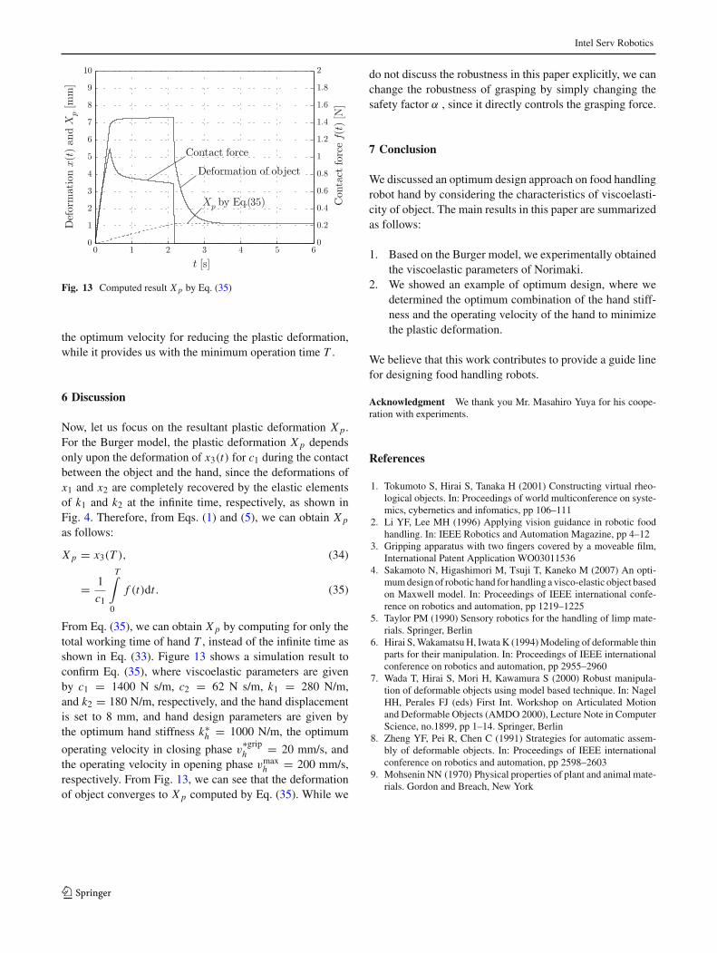
We perform simulation based on the viscoelastic parame-ters obtained by the experiments. Figure 11 shows the flow-chart for computing T and X p. For the hand motion in eachphase, x(t) can be computed by Eqs. (11) and (12). Insteadof using Eq. (33), the plastic deformation is computed byX p = x(T +Tinf), where Tinf is given large enough to ensurethat the object completes the recovering motion after relea-sed. Table 1 shows the parameters used for the simulation.Figure 12 shows the simulation result of the total workingtime T and the plastic deformation X p under the variableparameters of the hand stiffness kmin
h ≤ kh ≤ kmaxh and the
operating velocity vminh ≤ v
griph ≤ vmax
h . Based on the simu-lation result, we can solve the optimum design problem tominimize the plastic deformation X p as follows:
Minimize X p
Subject to f lim ≤ f (t), t lim1 ≤ t ≤ t lim
2 ,
t lim2 − t lim
1 ≥ Tl ,
T ≤ T max,
klimh ≤ kh,
vminh ≤ v
griph ≤ vmax
h ,
kminh ≤ kh ≤ kmax
h ,
where klimh , T max, and Xmax
p are the minimum hand stiff-ness, the permissible total working time, and the permissibleplastic deformation, respectively. By utilizing the exhaustive
Table 1 Parameters for simulation
k1 Single elastic parameter (N/m) 280
k2 Elastic parameter in the parallel unit (N/m) 180
c1 Single viscous parameter (N s/m) 1400
c2 Viscous parameter in the parallel unit (N s/m) 62
Tl Time for lifting object (s) 2.0
m Mass of object (kg) 0.045
µ Coefficient of friction 1.2
g Acceleration due to gravity (m/s2) 9.8
xgriph Root displacement of hand (mm) 8.0
vminh Minimum speed of the hand (mm/s) 10
vmaxh Maximum speed of the hand (mm/s) 200
kminh Minimum stiffness of hand (N/m) 500
kmaxh Maximum stiffness of hand (N/m) 5000
α Safety factor 3
Tinf Additional time for restoration of food (s) 3.0
Fig. 12 Simulation result
search method, we can compute the optimum operating velo-city v
∗griph and the optimum stiffness k∗
h to minimize the plas-tic deformation X p of food.
When klimh = 1000 N/m, T max = 2.20 s, and Xmax
p =1.2 mm are given, the minimum plastic deformation X p
obtained from Fig. 12 is X p = 1.12 mm (Point • indicated in
Fig. 12). In this case, v∗griph , k∗
h , and T are also obtained and
given by v∗griph = 20 mm/s, k∗
h = 1000 N/m, and T = 2.17 s,respectively. From the simulation result, we can see that theoptimum hand stiffness is obtained on the minimum boun-dary, while the optimum velocity is not on the boundary.From the geometrical shape of the graph in Fig. 12, the opti-mum point can be found on the plane corresponding to theminimum boundary of specified by kh = kmin
h . This meansthat the compliant gripper can contribute to avoid decreasingthe contact force for the change of shape of object due to theplastic deformation. On the other hand, it should be noted thatthe maximum velocity vmax
h does not always provide us with
123
Intel Serv Robotics
Fig. 13 Computed result X p by Eq. (35)
the optimum velocity for reducing the plastic deformation,while it provides us with the minimum operation time T .
6 Discussion
Now, let us focus on the resultant plastic deformation X p.For the Burger model, the plastic deformation X p dependsonly upon the deformation of x3(t) for c1 during the contactbetween the object and the hand, since the deformations ofx1 and x2 are completely recovered by the elastic elementsof k1 and k2 at the infinite time, respectively, as shown inFig. 4. Therefore, from Eqs. (1) and (5), we can obtain X p
as follows:
X p = x3(T ), (34)
= 1
c1
T∫
0
f (t)dt . (35)
From Eq. (35), we can obtain X p by computing for only thetotal working time of hand T , instead of the infinite time asshown in Eq. (33). Figure 13 shows a simulation result toconfirm Eq. (35), where viscoelastic parameters are givenby c1 = 1400 N s/m, c2 = 62 N s/m, k1 = 280 N/m,and k2 = 180 N/m, respectively, and the hand displacementis set to 8 mm, and hand design parameters are given bythe optimum hand stiffness k∗
h = 1000 N/m, the optimum
operating velocity in closing phase v∗griph = 20 mm/s, and
the operating velocity in opening phase vmaxh = 200 mm/s,
respectively. From Fig. 13, we can see that the deformationof object converges to X p computed by Eq. (35). While we
do not discuss the robustness in this paper explicitly, we canchange the robustness of grasping by simply changing thesafety factor α , since it directly controls the grasping force.
7 Conclusion
We discussed an optimum design approach on food handlingrobot hand by considering the characteristics of viscoelasti-city of object. The main results in this paper are summarizedas follows:
1. Based on the Burger model, we experimentally obtainedthe viscoelastic parameters of Norimaki.
2. We showed an example of optimum design, where wedetermined the optimum combination of the hand stiff-ness and the operating velocity of the hand to minimizethe plastic deformation.
We believe that this work contributes to provide a guide linefor designing food handling robots.
Acknowledgment We thank you Mr. Masahiro Yuya for his coope-ration with experiments.
References
1. Tokumoto S, Hirai S, Tanaka H (2001) Constructing virtual rheo-logical objects. In: Proceedings of world multiconference on syste-mics, cybernetics and infomatics, pp 106–111
2. Li YF, Lee MH (1996) Applying vision guidance in robotic foodhandling. In: IEEE Robotics and Automation Magazine, pp 4–12
3. Gripping apparatus with two fingers covered by a moveable film,International Patent Application WO03011536
4. Sakamoto N, Higashimori M, Tsuji T, Kaneko M (2007) An opti-mum design of robotic hand for handling a visco-elastic object basedon Maxwell model. In: Proceedings of IEEE international confe-rence on robotics and automation, pp 1219–1225
5. Taylor PM (1990) Sensory robotics for the handling of limp mate-rials. Springer, Berlin
6. Hirai S, Wakamatsu H, Iwata K (1994) Modeling of deformable thinparts for their manipulation. In: Proceedings of IEEE internationalconference on robotics and automation, pp 2955–2960
7. Wada T, Hirai S, Mori H, Kawamura S (2000) Robust manipula-tion of deformable objects using model based technique. In: NagelHH, Perales FJ (eds) First Int. Workshop on Articulated Motionand Deformable Objects (AMDO 2000), Lecture Note in ComputerScience, no.1899, pp 1–14. Springer, Berlin
8. Zheng YF, Pei R, Chen C (1991) Strategies for automatic assem-bly of deformable objects. In: Proceedings of IEEE internationalconference on robotics and automation, pp 2598–2603
9. Mohsenin NN (1970) Physical properties of plant and animal mate-rials. Gordon and Breach, New York
123