Embed Size (px)
Citation preview

Annex 16
Compatibility between towing vehicles and trailers with respect to ISO 11992 data
communications
附則16
ISO 11992のデータ通信に関する、牽引車両及び被牽引車の適合性
1. General 1. 一般要件
1.1. The requirements of this Annex shall only apply to towing vehicles and trailers
equipped with an electric control line as defined in paragraph 2.24. of the Regulation.
1.1. 本附則の要件は、本規則の2.24項に定義された電気式制御系を装備した牽引車
両及び被牽引車のみに適用する。
1.2. The ISO 7638 connector provides a power supply for the braking system or anti-lock
braking system of the trailer. In the case of vehicles equipped with an electric control line
as defined in paragraph 2.24. of the Regulation this connector also provides a data
communication interface via Pins 6 and 7 - see paragraph 5.1.3.6. of the Regulation.
1.2. ISO 7638コネクタは、被牽引車の制動装置又はアンチロックブレーキシステム
に対する電源を提供する。本規則の2.24項に定義された電気式制御系を装備した車
両の場合、このコネクタは、6番目のピン及び7番目のピンを介したデータ通信イン
ターフェースも提供する。本規則の5.1.3.6項を参照。
1.3. This Annex defines requirements applicable to the towing vehicle and trailer with
respect to the support of messages defined within ISO 11992-2:2003 including
Amd.1:2007.
1.3. 本附則は、ISO 11992-2:2003(2007年の同第1改訂版を含む)に定義されたメッ
セージへの対応に関して、牽引車両及び被牽引車に適用される要件を定める。
2. The parameters defined within ISO 11992-2:2003 including Amd.1:2007 that are
transmitted by the electric control line shall be supported as follows:
2. ISO 11992-2:2003(2007年の同第1改訂版を含む)に定義された、電気式制御系に
よって送信されるパラメータについては、下記の通り対応すること。
2.1. The following functions and associated messages are those specified within this
Regulation that shall be supported by the towing vehicle or trailer as appropriate:
2.1. 本規則で定めている、牽引車両又は被牽引車(該当する方)が対応すべき機能
及びこれに関連するメッセージは、下記の通り。
2.1.1. Messages transmitted from the towing vehicle to the trailer:
Function / Parameter ISO 11992-2:2003 Reference
Regulation No. 13 Reference
Service/secondary brake demand value EBS11 Byte 3-4 Annex 10, paragraph
3.1.3.2.
Two electrical circuits brake demand value EBS12 Byte 3 Bit 1-2 Regulation No. 13,
paragraph 5.1.3.2.
Pneumatic control line EBS12 Byte 3 Bit 5-6 Regulation No. 13, paragraph 5.1.3.2.
2.1.1. 牽引車両から被牽引車に送信されるメッセージ
機能/パラメータ ISO 11992-2:2003 の
参照対象 協定規則第 13 号の
参照先
主制動装置/ 二次制動装置要求値
EBS11 バイト 3-4 附則 10、3.1.3.2 項
2 つの電気回路からの ブレーキ要求値
EBS12 バイト 3 ビット 1-2 協定規則第 13 号、
5.1.3.2 項
空気圧式制御系 EBS12 バイト 3 ビット 5-6 協定規則第 13 号、
5.1.3.2 項
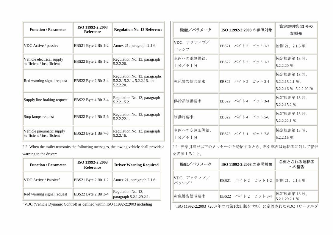
2.1.2. Messages transmitted from the trailer to the towing vehicle: 2.1.2. 被牽引車から牽引車両に送信されるメッセージ
Function / Parameter ISO 11992-2:2003 Reference Regulation No. 13 Reference
VDC Active / passive EBS21 Byte 2 Bit 1-2 Annex 21, paragraph 2.1.6.
Vehicle electrical supply sufficient / insufficient EBS22 Byte 2 Bit 1-2 Regulation No. 13, paragraph
5.2.2.20.
Red warning signal request EBS22 Byte 2 Bit 3-4Regulation No. 13, paragraphs 5.2.2.15.2.1., 5.2.2.16. and 5.2.2.20.
Supply line braking request EBS22 Byte 4 Bit 3-4 Regulation No. 13, paragraph 5.2.2.15.2.
Stop lamps request EBS22 Byte 4 Bit 5-6 Regulation No. 13, paragraph 5.2.2.22.1.
Vehicle pneumatic supply sufficient / insufficient EBS23 Byte 1 Bit 7-8 Regulation No. 13, paragraph
5.2.2.16.
機能/パラメータ ISO 11992-2:2003 の参照対象協定規則第 13 号の
参照先
VDC、アクティブ/
パッシブ EBS21 バイト 2 ビット 1-2 附則 21、2.1.6 項
車両への電気供給、
十分/不十分 EBS22 バイト 2 ビット 1-2
協定規則第 13 号、
5.2.2.20 項
赤色警告信号要求 EBS22 バイト 2 ビット 3-4
協定規則第 13 号、
5.2.2.15.2.1 項、
5.2.2.16 項 5.2.2.20 項
供給系制動要求 EBS22 バイト 4 ビット 3-4 協定規則第 13 号、
5.2.2.15.2 項
制動灯要求 EBS22 バイト 4 ビット 5-6 協定規則第 13 号、
5.2.2.22.1 項
車両への空気圧供給、
十分/不十分 EBS23 バイト 1 ビット 7-8
協定規則第 13 号、
5.2.2.16 項
2.2. When the trailer transmits the following messages, the towing vehicle shall provide a
warning to the driver:
Function / Parameter ISO 11992-2:2003 Reference Driver Warning Required
VDC Active / Passive1 EBS21 Byte 2 Bit 1-2 Annex 21, paragraph 2.1.6.
Red warning signal request EBS22 Byte 2 Bit 3-4 Regulation No. 13, paragraph 5.2.1.29.2.1.
1 VDC (Vehicle Dynamic Control) as defined within ISO 11992-2:2003 including
2.2. 被牽引車が以下のメッセージを送信するとき、牽引車両は運転者に対して警告
を表示すること。
機能/パラメータ ISO 11992-2:2003 の参照対象必要とされる運転者
への警告
VDC、アクティブ/ パッシブ 1 EBS21 バイト 2 ビット 1-2 附則 21、2.1.6 項
赤色警告信号要求 EBS22 バイト 2 ビット 3-4 協定規則第 13 号、
5.2.1.29.2.1 項 1 ISO 11992-2:2003(2007年の同第1改訂版を含む)に定義されたVDC(ビークルダ

Amd.1:2007 is defined within this Regulation as Vehicle Stability Function - see paragraph
2.34. of the Regulation.
イナミクスコントロール)は、本規則では車両安定機能として定義している。本規
則の2.34項を参照。
2.3. The following messages defined in ISO 11992-2:2003 including Amd.1:2007 shall be
supported by the towing vehicle or trailer:
2.3. 牽引車両又は被牽引車は、ISO 11992-2:2003(2007年の同第1改訂版を含む)に
定義された下記のメッセージに対応可能であること。
2.3.1. Messages transmitted from the towing vehicle to the trailer:
No messages currently defined.
2.3.1. 牽引車両から被牽引車に送信されるメッセージ
現時点において、定義されているメッセージはない。
2.3.2. Messages transmitted from the trailer to the towing vehicle:
Function / Parameter ISO 11992-2:2003 Reference
Vehicle service brake active / passive EBS22 Byte 1, Bit 5-6
Braking via electric control line supported EBS22 Byte 4, Bit 7-8
Geometric data index EBS24 Byte 1
Geometric data index content EBS24 Byte 2
2.3.2. 被牽引車から牽引車両に送信されるメッセージ:
機能/パラメータ ISO 11992-2:2003 の参照対象
車両主制動装置、作動/非作動 EBS22 バイト 1、ビット 5-6
電気式制御系を介した制動に対応 EBS22 バイト 4、ビット 7-8
幾何学的データ指標 EBS24 バイト 1
幾何学的データ指標の内容 EBS24 バイト 2
2.4. The following messages shall be supported by the towing vehicle or trailer as
appropriate when the vehicle is installed with a function associated with that parameter:
2.4. 車両に当該パラメータと関連する機能が搭載されている場合、牽引車両又は被
牽引車(該当する方)は下記のメッセージに対応していること。
2.4.1. Messages transmitted from the towing vehicle to the trailer:
Function / Parameter ISO 11992-2:2003 Reference
Vehicle type EBS11 Byte 2, Bit 3-4
VDC (Vehicle Dynamic Control) Active / passive2 EBS11 Byte 2, Bit 5-6
Brake demand value for front or left side of vehicle EBS11 Byte 7
Brake demand value for rear or right side of vehicle EBS11 Byte 8
ROP (Roll Over Protection) system enabled/disabled3 EBS12 Byte 1, Bit 3-4
YC (Yaw Control) system enabled/disabled4 EBS12 Byte 1, Bit 5-6
2.4.1. 牽引車両から被牽引車に送信されるメッセージ
機能/パラメータ ISO 11992-2:2003 の参照対象
車両型式 EBS11 バイト 2、ビット 3-4
VDC(ビークルダイナミクスコントロール)、アク
ティブ/パッシブ 2 EBS11 バイト 2、ビット 5-6
車両の前部又は左側に対する制動要求値 EBS11 バイト 7
車両の後部又は右側に対する制動要求値 EBS11 バイト 8
ROP(横転防止)システム、有効/無効 3 EBS12 バイト 1、ビット 3-4
YC(ヨー制御)システム、有効/無効 4 EBS12 バイト 1、ビット 5-6
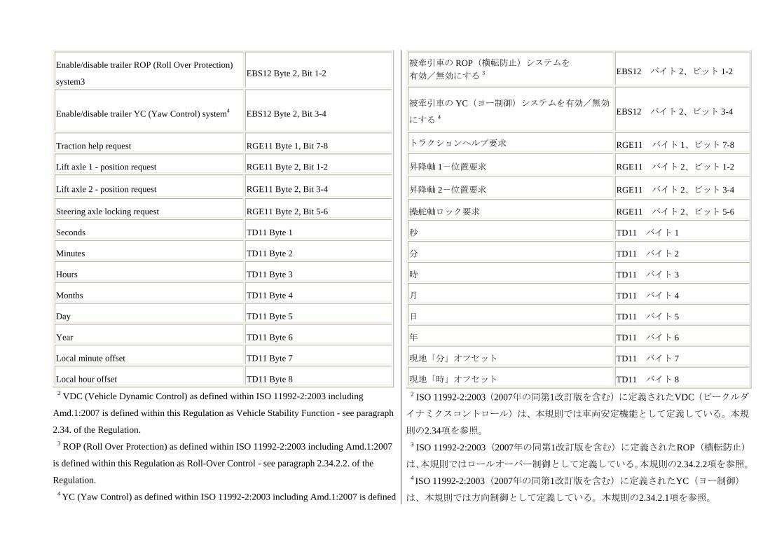
Enable/disable trailer ROP (Roll Over Protection)
system3 EBS12 Byte 2, Bit 1-2
Enable/disable trailer YC (Yaw Control) system4 EBS12 Byte 2, Bit 3-4
Traction help request RGE11 Byte 1, Bit 7-8
Lift axle 1 - position request RGE11 Byte 2, Bit 1-2
Lift axle 2 - position request RGE11 Byte 2, Bit 3-4
Steering axle locking request RGE11 Byte 2, Bit 5-6
Seconds TD11 Byte 1
Minutes TD11 Byte 2
Hours TD11 Byte 3
Months TD11 Byte 4
Day TD11 Byte 5
Year TD11 Byte 6
Local minute offset TD11 Byte 7
Local hour offset TD11 Byte 8 2 VDC (Vehicle Dynamic Control) as defined within ISO 11992-2:2003 including
Amd.1:2007 is defined within this Regulation as Vehicle Stability Function - see paragraph
2.34. of the Regulation. 3 ROP (Roll Over Protection) as defined within ISO 11992-2:2003 including Amd.1:2007
is defined within this Regulation as Roll-Over Control - see paragraph 2.34.2.2. of the
Regulation. 4 YC (Yaw Control) as defined within ISO 11992-2:2003 including Amd.1:2007 is defined
被牽引車の ROP(横転防止)システムを 有効/無効にする 3 EBS12 バイト 2、ビット 1-2
被牽引車の YC(ヨー制御)システムを有効/無効
にする 4 EBS12 バイト 2、ビット 3-4
トラクションヘルプ要求 RGE11 バイト 1、ビット 7-8
昇降軸 1-位置要求 RGE11 バイト 2、ビット 1-2
昇降軸 2-位置要求 RGE11 バイト 2、ビット 3-4
操舵軸ロック要求 RGE11 バイト 2、ビット 5-6
秒 TD11 バイト 1
分 TD11 バイト 2
時 TD11 バイト 3
月 TD11 バイト 4
日 TD11 バイト 5
年 TD11 バイト 6
現地「分」オフセット TD11 バイト 7
現地「時」オフセット TD11 バイト 8 2 ISO 11992-2:2003(2007年の同第1改訂版を含む)に定義されたVDC(ビークルダ
イナミクスコントロール)は、本規則では車両安定機能として定義している。本規
則の2.34項を参照。 3 ISO 11992-2:2003(2007年の同第1改訂版を含む)に定義されたROP(横転防止)
は、本規則ではロールオーバー制御として定義している。本規則の2.34.2.2項を参照。 4 ISO 11992-2:2003(2007年の同第1改訂版を含む)に定義されたYC(ヨー制御)
は、本規則では方向制御として定義している。本規則の2.34.2.1項を参照。

within this Regulation as Directional Control - see paragraph 2.34.2.1. of the Regulation.
2.4.2. Messages transmitted from the trailer to the towing vehicle:
Function / Parameter ISO 11992-2:2003 Reference
Support of side or axle wise brake force
distribution EBS21 Byte 2, Bit 3-4
Wheel based vehicle speed EBS21 Byte 3-4
Lateral acceleration EBS21 Byte 8
Vehicle ABS active / passive EBS22 Byte 1, Bit 1-2
Amber warning signal request EBS22 Byte 2, Bit 5-6
Vehicle type EBS22 Byte 3, Bit 5-6
Loading ramp approach assistance EBS22 Byte 4, Bit 1-2
Axle load sum EBS22 Byte 5-6
Tyre pressure sufficient / insufficient EBS23 Byte 1, Bit 1-2
Brake lining sufficient / insufficient EBS23 Byte 1, Bit 3-4
Brake temperature status EBS23 Byte 1, Bit 5-6
Tyre / wheel identification (pressure) EBS23 Byte 2
Tyre / wheel identification (lining) EBS23 Byte 3
Tyre / wheel identification (temperature) EBS23 Byte 4
Tyre pressure (actual tyre pressure) EBS23 Byte 5
Brake lining EBS23 Byte 6
Brake temperature EBS23 Byte 7
Brake cylinder pressure first axle left wheel EBS25 Byte 1
2.4.2. 被牽引車から牽引車両に送信されるメッセージ:
機能/パラメータ ISO 11992-2:2003 の参照対象
側部又は車軸における制動力配分への対応 EBS21 バイト 2、ビット 3-4
車輪に基づく車両速度 EBS21 バイト 3-4
横加速度 EBS21 バイト 8
車両 ABS、作動/非作動 EBS22 バイト 1、ビット 1-2
黄色警告信号要求 EBS22 バイト 2、ビット 5-6
車両型式 EBS22 バイト 3、ビット 5-6
ローディングランプ接近補助 EBS22 バイト 4、ビット 1-2
軸荷重合計 EBS22 バイト 5-6
タイヤ空気圧、十分/不十分 EBS23 バイト 1、ビット 1-2
ブレーキライニング、十分/不十分 EBS23 バイト 1、ビット 3-4
制動装置本体の温度状態 EBS23 バイト 1、ビット 5-6
タイヤ/車輪識別(圧力) EBS23 バイト 2
タイヤ/車輪識別(ライニング) EBS23 バイト 3
タイヤ/車輪識別(温度) EBS23 バイト 4
タイヤ空気圧(実際のタイヤ空気圧) EBS23 バイト 5
ブレーキライニング EBS23 バイト 6
制動装置本体の温度 EBS23 バイト 7
ブレーキシリンダー圧、第 1 車軸、左車輪 EBS25 バイト 1
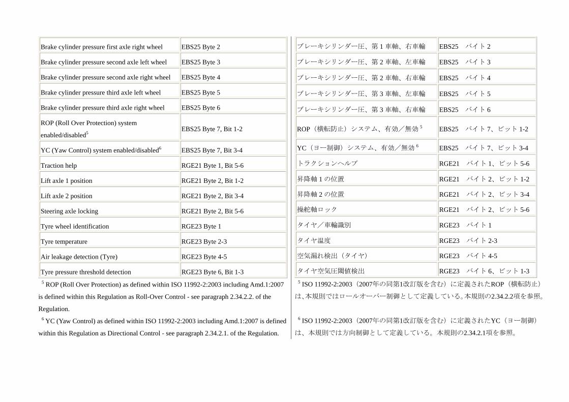
Brake cylinder pressure first axle right wheel EBS25 Byte 2
Brake cylinder pressure second axle left wheel EBS25 Byte 3
Brake cylinder pressure second axle right wheel EBS25 Byte 4
Brake cylinder pressure third axle left wheel EBS25 Byte 5
Brake cylinder pressure third axle right wheel EBS25 Byte 6
ROP (Roll Over Protection) system
enabled/disabled5 EBS25 Byte 7, Bit 1-2
YC (Yaw Control) system enabled/disabled6 EBS25 Byte 7, Bit 3-4
Traction help RGE21 Byte 1, Bit 5-6
Lift axle 1 position RGE21 Byte 2, Bit 1-2
Lift axle 2 position RGE21 Byte 2, Bit 3-4
Steering axle locking RGE21 Byte 2, Bit 5-6
Tyre wheel identification RGE23 Byte 1
Tyre temperature RGE23 Byte 2-3
Air leakage detection (Tyre) RGE23 Byte 4-5
Tyre pressure threshold detection RGE23 Byte 6, Bit 1-3 5 ROP (Roll Over Protection) as defined within ISO 11992-2:2003 including Amd.1:2007
is defined within this Regulation as Roll-Over Control - see paragraph 2.34.2.2. of the
Regulation. 6 YC (Yaw Control) as defined within ISO 11992-2:2003 including Amd.1:2007 is defined
within this Regulation as Directional Control - see paragraph 2.34.2.1. of the Regulation.
ブレーキシリンダー圧、第 1 車軸、右車輪 EBS25 バイト 2
ブレーキシリンダー圧、第 2 車軸、左車輪 EBS25 バイト 3
ブレーキシリンダー圧、第 2 車軸、右車輪 EBS25 バイト 4
ブレーキシリンダー圧、第 3 車軸、左車輪 EBS25 バイト 5
ブレーキシリンダー圧、第 3 車軸、右車輪 EBS25 バイト 6
ROP(横転防止)システム、有効/無効 5 EBS25 バイト 7、ビット 1-2
YC(ヨー制御)システム、有効/無効 6 EBS25 バイト 7、ビット 3-4
トラクションヘルプ RGE21 バイト 1、ビット 5-6
昇降軸 1 の位置 RGE21 バイト 2、ビット 1-2
昇降軸 2 の位置 RGE21 バイト 2、ビット 3-4
操舵軸ロック RGE21 バイト 2、ビット 5-6
タイヤ/車輪識別 RGE23 バイト 1
タイヤ温度 RGE23 バイト 2-3
空気漏れ検出(タイヤ) RGE23 バイト 4-5
タイヤ空気圧閾値検出 RGE23 バイト 6、ビット 1-3 5 ISO 11992-2:2003(2007年の同第1改訂版を含む)に定義されたROP(横転防止)
は、本規則ではロールオーバー制御として定義している。本規則の2.34.2.2項を参照。
6 ISO 11992-2:2003(2007年の同第1改訂版を含む)に定義されたYC(ヨー制御)
は、本規則では方向制御として定義している。本規則の2.34.2.1項を参照。

2.5.
The support of all other messages defined within ISO 11992-2:2003 including Amd.1:2007
is optional for the towing vehicle and trailer.
2.5.
ISO 11992-2:2003(2007年の同第1改訂版を含む)に定義された、その他全てのメッ
セージへの対応については、牽引車両及び被牽引車においては任意である。
Annex 17
Test procedure to assess the functional compatibility of vehicles equipped with electric
control lines
附則17
電気式制御系を装備した車両の機能的適合性を評価するための試験手順
1. General 1. 一般要件
1.1. This annex defines a procedure that may be used to check towing and towed vehicles
equipped with an electric control line against the functional and performance requirements
referred to in paragraph 5.1.3.6.1. of this Regulation. Alternative procedures may be used at
the discretion of the Technical Service if an equivalent level of checking integrity can be
established.
1.1. 本附則では、電気式制御系を装備した牽引車両及び被牽引車両を、本規則の
5.1.3.6.1項.に明記された機能要件及び性能要件に照らして確認するために使用でき
る手順を定める。確認にあたって同程度の妥当性が確立できれば、試験機関の判断
においてこれに代わる手順を使用してもよい。
1.2. The references to ISO 7638 within this annex apply to ISO 7638-1:2003 for 24V
applications and ISO 7638-2:2003 for 12V applications.
1.2. 本附則内のISO 7638に関する記載は、24 Vで使用する場合はISO 7638-1:2003に
適用し、12 Vで使用する場合はISO 7638-2:2003に適用する。
2. Information document 2. 資料文書
2.1. The vehicle manufacturer/system supplier shall supply to the Technical Service an
Information Document that contains at least the following:
2.1. 車両メーカーならびにシステムメーカーは、少なくとも下記を記載した資料文
書を試験機関に提出すること。
2.1.1. A schematic of the vehicle braking system; 2.1.1. 車両制動装置の概略図。
2.1.2. Evidence that the interface, including the physical layer, data link layer and the
application layer and the respective position of supported messages and parameters,
complies with ISO 11992;
2.1.2. 物理層、データリンク層及びアプリケーション層を含むインターフェース、
及び対応可能なメッセージ及びパラメータそれぞれの配置がISO 11992に適合する
ことの証明。
2.1.3. A list of supported messages and parameters; and 2.1.3. 対応可能なメッセージ及びパラメータのリスト。
2.1.4. The specification of the motor vehicle with respect to the number of control circuits
that signal the pneumatic and/or electric control lines.
2.1.4. 空気圧式制御系又は電気式制御系信号を発する制御回路の数に関する、自動
車の仕様。
3. Towing vehicles 3. 牽引自動車
3.1. ISO 11992 trailer simulator 3.1. ISO 11992に準拠した被牽引車シミュレータ

The simulator shall: 当該シミュレータは、下記の条件を満たしていること。
3.1.1. Have a connector meeting ISO 7638:2003 (7 pin) to connect to the vehicle under test.
Pins 6 and 7 of the connector shall be used to transmit and receive messages complying
with ISO 11992:2003 including ISO 11992-2:2003 and its Amd-1:2007;
3.1.1. 試験対象車両に接続するため、ISO 7638:2003(7ピン)に適合するコネクタ
を有すること。コネクタの6番目のピン及び7番目のピンは、ISO 11992:2003(ISO
11992-2:2003及びAmd-1:2007を含む)に適合するメッセージの送信及び受信を行う
ために使うものとする。
3.1.2. Be capable of receiving all of the messages transmitted by the motor vehicle to be
type approved and be capable of transmitting all trailer messages defined within ISO
11992-2:2003;
3.1.2. 型式認可を受ける自動車が送信するメッセージの全てを受信でき、かつ、ISO
11992-2:2003に定義された被牽引車メッセージを全て送信できること。
3.1.3. Provide a direct or indirect readout of messages, with the parameters in the data field
shown in the correct order relative to time; and
3.1.3. メッセージの直接的又は間接的な読み出し情報を提供し、データフィールド
のパラメータを時系列において正確な順番で表示すること。
3.1.4. Include a facility to measure coupling head response time in accordance with
paragraph 2.6. of Annex 6 to this Regulation.
3.1.4. 本規則、附則6の2.6項に従って、連結部の応答時間を測定する機能を備える
こと。
3.2. Checking procedure 3.2. 確認手順
3.2.1. Confirm that the manufacturer's/supplier's information document demonstrates
compliance with the provisions of ISO 11992 with respect to the physical layer, data link
layer and application layer.
3.2.1. 車両メーカーならびにシステムメーカーの資料文書によって物理層、データ
リンク層及びアプリケーション層に関してISO 11992の規定への適合性が証明され
ることを確認する。
3.2.2. Check the following, with the simulator connected to the motor vehicle via the ISO
7638 interface and whilst all trailer messages relevant to the interface are being transmitted:
3.2.2. シミュレータをISO 7638インターフェースを介して自動車に接続し、同イン
ターフェースに関連する被牽引車からのメッセージが全て送信されている状態で、
下記を確認する。
3.2.2.1. Control line signalling: 3.2.2.1. 制御系の発信信号
3.2.2.1.1.
The parameters defined in EBS 12 byte 3 of ISO 11992-2:2003 shall be checked against the
specification of the vehicle as follows:
Control Line Signalling EBS 12 Byte 3
Bits 1 - 2 Bits 5 - 6
Service braking demand generated from one electrical circuit 00b
3.2.2.1.1.
ISO 11992-2:2003のEBS 12バイト3に定義されたパラメータを、車両の仕様に照らし
て下記の通り確認する。
制御系の発信信号 EBS12 バイト 3
ビット 1-2 ビット 5-6
1 つの電気回路から主制動要求が発生 00b
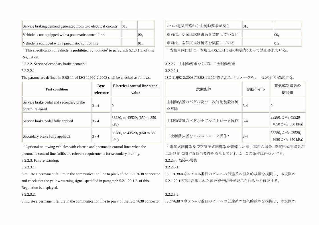
Service braking demand generated from two electrical circuits 01b
Vehicle is not equipped with a pneumatic control line1 00b
Vehicle is equipped with a pneumatic control line 01b
1 This specification of vehicle is prohibited by footnote4 to paragraph 5.1.3.1.3. of this
Regulation.
2 つの電気回路から主制動要求が発生 01b
車両は、空気圧式制御系を装備していない 1 00b
車両は、空気圧式制御系を装備している 01b 1 当該車両仕様は、本規則の5.1.3.1.3項の脚注4によって禁止されている。
3.2.2.2. Service/Secondary brake demand: 3.2.2.2. 主制動要求ならびに二次制動要求
3.2.2.2.1.
The parameters defined in EBS 11 of ISO 11992-2:2003 shall be checked as follows:
Test condition Byte
reference
Electrical control line signal
value
Service brake pedal and secondary brake
control released 3 - 4 0
Service brake pedal fully applied 3 - 4 33280d to 43520d (650 to 850
kPa)
Secondary brake fully applied2 3 - 4 33280d to 43520d (650 to 850
kPa) 2 Optional on towing vehicles with electric and pneumatic control lines when the
pneumatic control line fulfils the relevant requirements for secondary braking.
3.2.2.2.1.
ISO 11992-2:2003のEBS 11に定義されたパラメータを、下記の通り確認する。
試験条件 参照バイト 電気式制御系の
信号値
主制動装置のペダル及び二次制動装置制御
を解除 3-4 0
主制動装置のペダルをフルストローク操作 3-4 33280dから 43520d
(650 から 850 kPa)
二次制動装置をフルストローク操作 2 3-4 33280dから 43520d
(650 から 850 kPa)
2 電気式制御系及び空気圧式制御系を装備した牽引車両の場合、空気圧式制御系が
二次制動に関する該当要件を満たしていれば、この条件は任意とする。
3.2.2.3. Failure warning: 3.2.2.3. 故障の警告
3.2.2.3.1.
Simulate a permanent failure in the communication line to pin 6 of the ISO 7638 connector
and check that the yellow warning signal specified in paragraph 5.2.1.29.1.2. of this
Regulation is displayed.
3.2.2.3.1.
ISO 7638コネクタの6番目のピンへの伝達系の恒久的故障を模擬し、本規則の
5.2.1.29.1.2項に記載された黄色警告信号が表示されるかを確認する。
3.2.2.3.2.
Simulate a permanent failure in the communication line to pin 7 of the ISO 7638 connector
3.2.2.3.2.
ISO 7638コネクタの7番目のピンへの伝達系の恒久的故障を模擬し、本規則の

and check that the yellow warning signal specified in paragraph 5.2.1.29.1.2. of this
Regulation is displayed.
5.2.1.29.1.2項に記載された黄色警告信号が表示されるかを確認する。
3.2.2.3.3. Simulate message EBS 22, byte 2 with bits 3 - 4 set to 01b and check that the red
warning signal specified in paragraph 5.2.1.29.1.1. of this Regulation is displayed.
3.2.2.3.3. ビット3-4を01bに設定した状態でメッセージEBS 22、バイト2を模擬し、
本規則の5.2.1.29.1.1項に記載された赤色警告信号が表示されるかを確認する。
3.2.2.4. Supply line braking request:
For power-driven vehicles which can be operated with trailers connected via an electric
control line only:
Only the electric control line shall be connected.
Simulate message EBS 22, byte 4 with bits 3 - 4 set to 01b and check that when the service
brake, secondary brake or parking brake is fully actuated the pressure in the supply line
falls to 150 kPa within the following two seconds.
Simulate a continuous absence of data communication and check that when the service
brake, secondary brake or parking brake is fully actuated the pressure in the supply line
falls to 150 kPa within the following two seconds.
3.2.2.4. 供給系の制動要求
電気式制御系のみを介して被牽引車を接続して操作することが可能な自動車であ
る場合:
電気式制御系のみ接続する。
ビット3-4を01bに設定してメッセージEBS 22、バイト4を模擬した上で、主制動装置、
二次制動装置、又は駐車制動装置が完全に作動したときに、供給系内の圧力がその
後2秒以内に150 kPaまで低下するかを確認する。
データ通信の連続的欠如を模擬して、主制動装置、二次制動装置、又は駐車制動装
置が完全に作動したときに、供給系内の圧力がその後2秒以内に150 kPaまで低下す
るかを確認する。
3.2.2.5. Response time: 3.2.2.5. 応答時間
3.2.2.5.1. Check that, with no faults present, the control line response requirements defined
in paragraph 2.6. of Annex 6 to this Regulation are met.
3.2.2.5.1. 故障がない状態で、本規則、附則6の2.6項に定義した制御系の応答要件が
満たされていることを確認する。
3.2.2.6. Illumination of stop lamps
Simulate message EBS 22 byte 4 bits 5 to 6 set to 00 and check that the stop lamps are not
illuminated.
Simulate message EBS 22 byte 4 bits 5 to 6 set to 01 and check that the stop lamps are
illuminated.
3.2.2.6. 制動灯の点灯
メッセージEBS 22バイト4ビット5-6が00に設定された状態を模擬し、制動灯が点灯
しないことを確認する。
メッセージEBS 22バイト4ビット5-6が01に設定された状態を模擬し、制動灯が点灯
することを確認する。
3.2.2.7. Intervention of Trailer Stability Function
Simulate message EBS 21 byte 2 bits 1 to 2 set to 00 and check that the driver warning
defined in paragraph 2.1.6. of Annex 21 is not illuminated.
Simulate message EBS 21 byte 2 bits 1 to 2 set to 01 and check that the driver warning
defined in paragraph 2.1.6. of Annex 21 is illuminated.
3.2.2.7. 被牽引車の車両安定機能の介入
メッセージEBS 21バイト2ビット1-2が00に設定された状態を模擬し、附則21の2.1.6
項に定義された運転者への警告表示が点灯しないことを確認する。
メッセージEBS 21バイト2ビット1-2が01に設定された状態を模擬し、附則21の2.1.6
項に定義された運転者への警告表示が点灯することを確認する。

3.2.3. Additional checks 3.2.3. 追加確認
3.2.3.1. At the discretion of the Technical Service the checking procedures defined above
may be repeated with the non-braking functions relevant to the interface in different states
or switched off.
3.2.3.1. 試験機関の判断において、インターフェースに関連する非制動機能を異な
る状態にして、又は電源をオフにして、上記の確認手順を繰り返してもよい。
3.2.3.2. Paragraph 2.4.1. of Annex 16 defines additional messages that shall under specific
circumstances be supported by the towing vehicle. Additional checks may be carried out to
verify the status of supported messages to ensure the requirements of paragraph 5.1.3.6.2.
of the Regulation are fulfilled.
3.2.3.2. 附則16の2.4.1項では、特定の状況下において牽引自動車が対応するべきそ
の他のメッセージを規定している。本規則の5.1.3.6.2項の要件が満たされているこ
とを確保するため、対応しているメッセージの状態を検証する追加確認を実施して
もよい。
4. Trailers 4. 被牽引車
4.1. ISO 11992 towing vehicle simulator
The simulator shall:
4.1. ISO 11992に準拠した牽引車両シミュレータ
シミュレータは、下記の条件を満たしていること。
4.1.1. Have a connector meeting ISO 7638:2003 (7 pin) to connect to the vehicle under test.
Pins 6 and 7 of the connector shall be used to transmit and receive messages complying
with ISO 11992:2003 including ISO 11992-2:2003 and its Amd.1:2007;
4.1.1. 試験対象車両に接続するためにISO 7638:2003(7ピン)に適合するコネクタ
を有すること。コネクタの6番目のピン及び7番目のピンは、ISO 11992:2003(ISO
11992-2:2003及び2007年の同第1改訂版を含む)に適合するメッセージを送信及び受
信するために使うものとする。
4.1.2. Have a failure warning display and an electrical power supply for the trailer; 4.1.2. 被牽引車用の故障警告ディスプレイ及び電源を有すること。
4.1.3. Shall be capable of receiving all of the messages transmitted by the trailer to be type
approved and be capable of transmitting all motor vehicle messages defined within ISO
11992-2:2003.
4.1.3. 型式認可を受ける被牽引車が送信するメッセージの全てを受信でき、かつ、
ISO 11992-2:2003に定義された自動車メッセージを全て送信できること。
4.1.4. Provide a direct or indirect readout of messages with the parameters in the data field
shown in the correct order relative to time; and
4.1.4. メッセージの直接的又は間接的な読み出し情報を提供し、データフィールド
のパラメータを時系列において正確な順番で表示すること。
4.1.5. Include a facility to measure brake system response time in accordance with
paragraph 3.5.2. of Annex 6 to this Regulation.
4.1.5. 本規則、附則6の3.5.2項に従って、制動装置の応答時間を測定する機能を備え
ていること。
4.2. Checking procedure 4.2. 確認手順
4.2.1. Confirm that the manufacturer's/supplier's Information Document demonstrates
compliance with the provisions of ISO 11992:2003 including ISO 11992-2:2003 and its
Amd.1:2007 with respect to the physical layer, data link layer and application layer.
4.2.1. 車両メーカーならびにシステムメーカーの資料文書によって物理層、データ
リンク層及びアプリケーション層に関してISO 11992:2003(ISO 11992-2:2003及び
2007年の同第1改訂版を含む)の規定への適合性が証明されることを確認する。

4.2.2. Check the following, with the simulator connected to the trailer via the ISO 7638
interface and whilst all towing vehicle messages relevant to the interface are being
transmitted:
4.2.2. シミュレータをISO 7638インターフェースを介して被牽引車に接続し、同イ
ンターフェースに関連する牽引自動車からのメッセージが全て送信されている状
態で、下記を確認する。
4.2.2.1. Service brake system function: 4.2.2.1. 主制動装置の機能
4.2.2.1.1. The trailer response to the parameters defined in EBS 11 of ISO 11992-2:2003
including ISO 11992-2:2003 and its Amd.1:2007 shall be checked as follows:
The pressure in the supply line at the start of each test shall be > 700 kPa and the vehicle
shall be laden (the loading condition may be simulated for the purpose of this check).
4.2.2.1.1. ISO 11992-2:2003(ISO 11992-2:2003及び2007年の同第1改訂版を含む)の
EBS 11に定義されたパラメータに対する被牽引車の応答を、下記の通り確認する。
各試験の開始時点における供給系の圧力は700 kPa以上であり、車両は積載状態にす
る(この確認においては、積載条件は模擬によるものでもよい)。
4.2.2.1.1.1. For trailers equipped with pneumatic and electric control lines:
Both control lines shall be connected;
Both control lines shall be signalled simultaneously;
The simulator shall transmit message byte 3, bits 5-6;
Of EBS 12 set to 01b to indicate to the trailer that a pneumatic control line should be
connected.
Parameters to be checked:
Message transmitted by the simulator Pressure at the brake chambers
Byte reference Digital demand value
3 - 4 0 0 kPa
3 - 4 33280d
(650 kPa)
As defined in the vehicle
manufacturer's brake calculation
4.2.2.1.1.1. 空気圧式制御系及び電気式制御系を装備した被牽引車である場合:
両方の制御系を接続する。
両方の制御系に同時に信号を送信する。
シミュレータは、EBS 12のバイト3、ビット5-6のメッセージを01bに設定して送信し、
空気圧式制御系の接続が必要であることを被牽引車に表示すること。
下記のパラメータを確認する。
シミュレータによって送信されるメッセージ ブレーキチャンバーにおける圧力
参照バイト デジタル要求値
3-4 0 0 kPa
3-4 33280d
(650 kPa)
車両メーカーによる制動計算の定義
に従う
4.2.2.1.1.2. Trailers equipped with pneumatic and electric control lines or an electric
control line only:
Only the electric control line shall be connected
The simulator shall transmit the following messages:
Byte 3, bits 5 - 6 of EBS 12 set to 00b to indicate to the trailer that a pneumatic control line
4.2.2.1.1.2. 空気圧式制御系及び電気式制御系、又は電気式制御系のみを装備した被
牽引車である場合:
電気式制御系のみ接続する。
シミュレータは、下記のメッセージを送信すること。
EBS 12のバイト3、ビット5-6を00bに設定して、空気圧式制御系がないことを被牽引
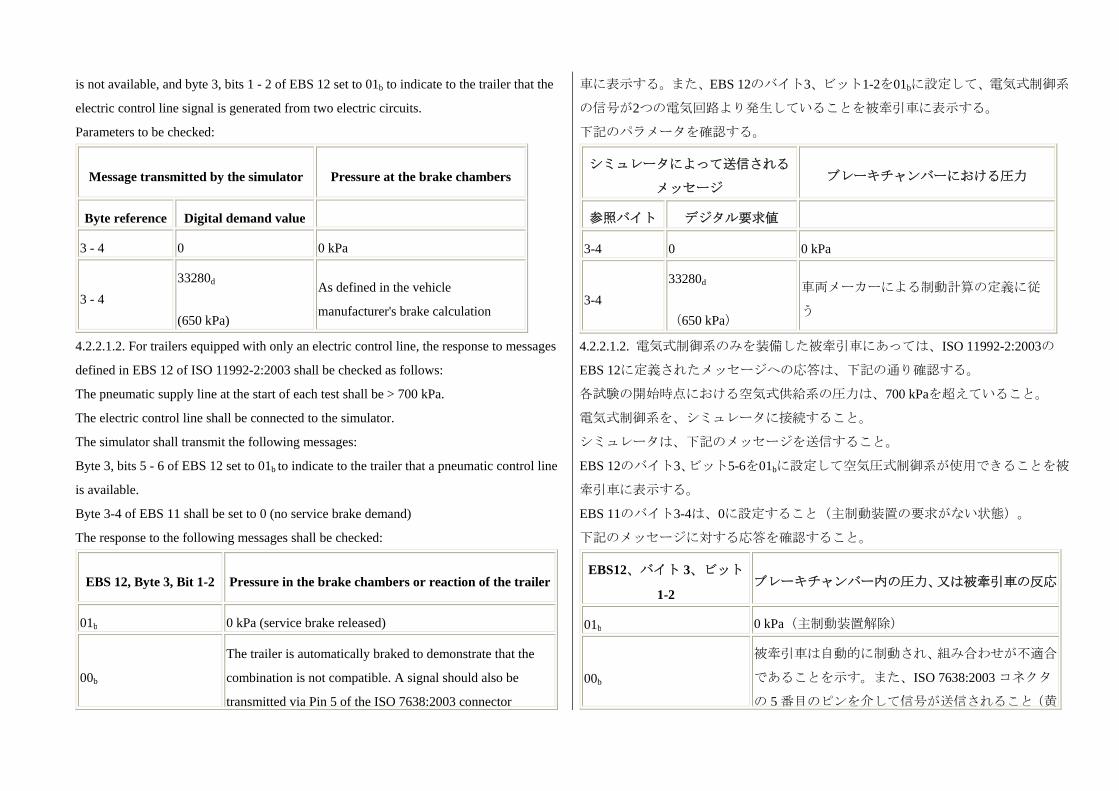
is not available, and byte 3, bits 1 - 2 of EBS 12 set to 01b to indicate to the trailer that the
electric control line signal is generated from two electric circuits.
Parameters to be checked:
Message transmitted by the simulator Pressure at the brake chambers
Byte reference Digital demand value
3 - 4 0 0 kPa
3 - 4 33280d
(650 kPa)
As defined in the vehicle
manufacturer's brake calculation
車に表示する。また、EBS 12のバイト3、ビット1-2を01bに設定して、電気式制御系
の信号が2つの電気回路より発生していることを被牽引車に表示する。
下記のパラメータを確認する。
シミュレータによって送信される
メッセージ ブレーキチャンバーにおける圧力
参照バイト デジタル要求値
3-4 0 0 kPa
3-4 33280d
(650 kPa)
車両メーカーによる制動計算の定義に従
う
4.2.2.1.2. For trailers equipped with only an electric control line, the response to messages
defined in EBS 12 of ISO 11992-2:2003 shall be checked as follows:
The pneumatic supply line at the start of each test shall be > 700 kPa.
The electric control line shall be connected to the simulator.
The simulator shall transmit the following messages:
Byte 3, bits 5 - 6 of EBS 12 set to 01b to indicate to the trailer that a pneumatic control line
is available.
Byte 3-4 of EBS 11 shall be set to 0 (no service brake demand)
The response to the following messages shall be checked:
EBS 12, Byte 3, Bit 1-2 Pressure in the brake chambers or reaction of the trailer
01b 0 kPa (service brake released)
00b
The trailer is automatically braked to demonstrate that the
combination is not compatible. A signal should also be
transmitted via Pin 5 of the ISO 7638:2003 connector
4.2.2.1.2. 電気式制御系のみを装備した被牽引車にあっては、ISO 11992-2:2003の
EBS 12に定義されたメッセージへの応答は、下記の通り確認する。
各試験の開始時点における空気式供給系の圧力は、700 kPaを超えていること。
電気式制御系を、シミュレータに接続すること。
シミュレータは、下記のメッセージを送信すること。
EBS 12のバイト3、ビット5-6を01bに設定して空気圧式制御系が使用できることを被
牽引車に表示する。
EBS 11のバイト3-4は、0に設定すること(主制動装置の要求がない状態)。
下記のメッセージに対する応答を確認すること。
EBS12、バイト 3、ビット
1-2 ブレーキチャンバー内の圧力、又は被牽引車の反応
01b 0 kPa(主制動装置解除)
00b
被牽引車は自動的に制動され、組み合わせが不適合
であることを示す。また、ISO 7638:2003 コネクタ
の 5 番目のピンを介して信号が送信されること(黄

(yellow warning).
色の警告信号)。
4.2.2.1.3. For trailers connected with only an electrical control line, the response of the
trailer to a failure in the electric control transmission of the trailer which results in a
reduction in braking performance to at least 30 per cent of the prescribed value shall be
checked by the following procedure:
The pneumatic supply line at the start of each test shall be > 700 kPa.
The electric control line shall be connected to the simulator.
Byte 3, bits 5-6 of EBS 12 set to 00b to indicate to the trailer that a pneumatic control line is
not available.
Byte 3, bits 1-2 of EBS 12 set to 01b to indicate to the trailer that the electric control line
signal is generated from two independent circuits.
The following shall be checked:
Test condition Braking system response
With no faults present in the trailer
braking system
Check that the braking system is
communicating with the simulator and that
Byte 4, bits 3-4 of EBS 22 is set to 00b.
Introduce a failure in the electric control
transmission of the trailer braking system
that prevents at least 30 per cent of the
prescribed braking performance from
being maintained
Check that Byte 4, bits 3-4 of EBS 22 is set to
01b
Or
The data communications to the simulator has
been terminated
4.2.2.1.3. 電気式制御系にのみ接続した被牽引車にあっては、所定の値の少なくとも
30%まで制動性能の低下を引き起こすような、被牽引車の電気制御伝達装置の不具
合に対する応答について、下記の手順で確認する。
各試験開始時における空気式供給系の圧力は、700 kPa以上であること。
電気式制御系を、シミュレータに接続すること。
EBS12のバイト3、ビット5-6を00bに設定して、空気圧式制御系が使用できないこと
を被牽引車に表示する。
EBS12のバイト3、ビット1-2を01bに設定して、電気式制御系の信号が独立した2つ
の回路から発生することを被牽引車に表示する。
下記について確認すること。
試験条件 制動装置の応答
被牽引車の制動装置には故障な
し
制動装置がシミュレータと通信しているか、
及び、EBS 22 のバイト 4、ビット 3-4 が 00b
に設定されるかを確認する。
被牽引車の制動装置の電気制御
伝達装置に、所定の制動性能の少
なくとも 30%を維持することを
妨げる故障を発生させる。
EBS 22 のバイト 4、ビット 3-4 が 01bに設定
されているかを確認する。
又は
シミュレータへのデータ通信が終了している
かを確認する。
4.2.2.2. Failure warning 4.2.2.2. 故障の警告
4.2.2.2.1. Check that the appropriate warning message or signal is transmitted under the 4.2.2.2.1. 該当する警告メッセージ又は信号が、下記の条件により送信されることを
following conditions: 確認する。
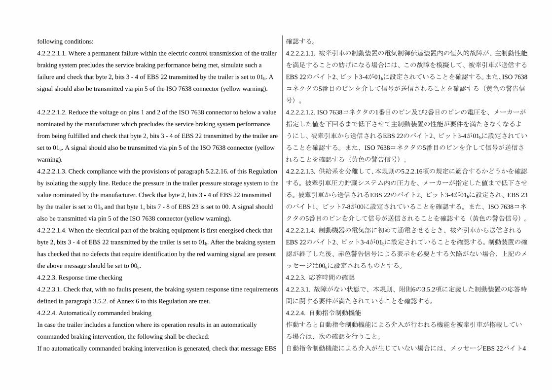
4.2.2.2.1.1. Where a permanent failure within the electric control transmission of the trailer
braking system precludes the service braking performance being met, simulate such a
failure and check that byte 2, bits 3 - 4 of EBS 22 transmitted by the trailer is set to 01b. A
signal should also be transmitted via pin 5 of the ISO 7638 connector (yellow warning).
4.2.2.2.1.1. 被牽引車の制動装置の電気制御伝達装置内の恒久的故障が、主制動性能
を満足することの妨げになる場合には、この故障を模擬して、被牽引車が送信する
EBS 22のバイト2、ビット3-4が01bに設定されていることを確認する。また、ISO 7638
コネクタの5番目のピンを介して信号が送信されることを確認する(黄色の警告信
号)。
4.2.2.2.1.2. Reduce the voltage on pins 1 and 2 of the ISO 7638 connector to below a value
nominated by the manufacturer which precludes the service braking system performance
from being fulfilled and check that byte 2, bits 3 - 4 of EBS 22 transmitted by the trailer are
set to 01b. A signal should also be transmitted via pin 5 of the ISO 7638 connector (yellow
warning).
4.2.2.2.1.2. ISO 7638コネクタの1番目のピン及び2番目のピンの電圧を、メーカーが
指定した値を下回るまで低下させて主制動装置の性能が要件を満たさなくなるよ
うにし、被牽引車から送信されるEBS 22のバイト2、ビット3-4が01bに設定されてい
ることを確認する。また、ISO 7638コネクタの5番目のピンを介して信号が送信さ
れることを確認する(黄色の警告信号)。
4.2.2.2.1.3. Check compliance with the provisions of paragraph 5.2.2.16. of this Regulation
by isolating the supply line. Reduce the pressure in the trailer pressure storage system to the
value nominated by the manufacturer. Check that byte 2, bits 3 - 4 of EBS 22 transmitted
by the trailer is set to 01b and that byte 1, bits 7 - 8 of EBS 23 is set to 00. A signal should
also be transmitted via pin 5 of the ISO 7638 connector (yellow warning).
4.2.2.2.1.3. 供給系を分離して、本規則の5.2.2.16項の規定に適合するかどうかを確認
する。被牽引車圧力貯蔵システム内の圧力を、メーカーが指定した値まで低下させ
る。被牽引車から送信されるEBS 22のバイト2、ビット3-4が01bに設定され、EBS 23
のバイト1、ビット7-8が00に設定されていることを確認する。また、ISO 7638コネ
クタの5番目のピンを介して信号が送信されることを確認する(黄色の警告信号)。
4.2.2.2.1.4. When the electrical part of the braking equipment is first energised check that
byte 2, bits 3 - 4 of EBS 22 transmitted by the trailer is set to 01b. After the braking system
has checked that no defects that require identification by the red warning signal are present
the above message should be set to 00b.
4.2.2.2.1.4. 制動機器の電気部に初めて通電させるとき、被牽引車から送信される
EBS 22のバイト2、ビット3-4が01bに設定されていることを確認する。制動装置の確
認が終了した後、赤色警告信号による表示を必要とする欠陥がない場合、上記のメ
ッセージは00bに設定されるものとする。
4.2.2.3. Response time checking 4.2.2.3. 応答時間の確認
4.2.2.3.1. Check that, with no faults present, the braking system response time requirements
defined in paragraph 3.5.2. of Annex 6 to this Regulation are met.
4.2.2.3.1. 故障がない状態で、本規則、附則6の3.5.2項に定義した制動装置の応答時
間に関する要件が満たされていることを確認する。
4.2.2.4. Automatically commanded braking
In case the trailer includes a function where its operation results in an automatically
commanded braking intervention, the following shall be checked:
If no automatically commanded braking intervention is generated, check that message EBS
4.2.2.4. 自動指令制動機能
作動すると自動指令制動機能による介入が行われる機能を被牽引車が搭載してい
る場合は、次の確認を行うこと。
自動指令制動機能による介入が生じていない場合には、メッセージEBS 22バイト4

22 byte 4 bits 5 to 6 are set to 00.
Simulate an automatically commanded braking intervention, when the resulting
deceleration is > 0.7 m/sec2, check that message EBS 22 byte 4 bits 5 to 6 are set to 01.
ビット5-6が00に設定されていることを確認する。
自動指令制動機能の介入を模擬し、結果として生じる減速が0.7 m/sec2未満のとき、
メッセージEBS 22バイト4ビット5-6が01に設定されていることを確認する。
4.2.2.5. Vehicle stability function
In the case of a trailer equipped with a vehicle stability function, the following checks shall
be carried out:
When the vehicle stability function is inactive, check that message EBS 21 byte 2 bits 1 to
2 are set to 00.
Simulate an intervention of the vehicle stability control function as specified in paragraph
2.2.4. of Annex 21 and check that message EBS 21 byte 2 bits 1 to 2 are set to 01.
4.2.2.5. 車両安定機能
車両安定機能を装備した被牽引車である場合は、次の確認を行うこと。
車両安定機能が非作動状態のとき、メッセージEBS 21バイト2ビット1-2が00に設定
されていることを確認する。
附則21の2.2.4項に規定した通りに車両安定制御機能の介入を模擬し、メッセージ
EBS 21バイト2ビット1-2が01に設定されていることを確認する。
4.2.2.6. Support of the electric control line
Where the trailer braking system does not support braking via the electric control line
check that message EBS 22 byte 4 bits 7 to 8 are set to 00.
Where the trailer braking system supports the electric control line, check that message EBS
22 byte 4 bits 7 to 8 are set to 01.
4.2.2.6. 電気式制御系の対応状況
被牽引車の制動装置が、電気式制御系を介した制動に対応していない場合は、メッ
セージEBS 22バイト4ビット7-8が00に設定されていることを確認する。
被牽引車の制動装置が、電気式制御系を介した制動に対応している場合は、メッセ
ージEBS 22バイト4ビット7-8が01に設定されていることを確認する。
4.2.3. Additional checks 4.2.3. 追加確認
4.2.3.1. At the discretion of the Technical Service the checking procedures defined above
may be repeated with the non-braking messages relevant to the interface in different states
or switched off.
Where repeat measurements of the brake system response time are carried out, variations in
the value recorded may occur due to the reaction of the vehicle pneumatics. In all cases the
prescribed response time requirements shall be met.
4.2.3.1. 試験機関の判断において、インターフェースに関連する非制動メッセージ
を異なる状態にして、又は電源をオフにして、上記の確認手順を繰り返してもよい。
制動装置の応答時間の反復測定を実施する場合、車両の空気タイヤの反応によっ
て、記録される値に変動が生じる場合がある。全ての場合において、所定の応答時
間の要件が満たされること。
4.2.3.2. Paragraph 2.4.2. of Annex 16 defines additional messages that shall under specific
circumstances be supported by the trailer. Additional checks may be carried out to verify
the status of supported messages to ensure the requirements of paragraph 5.1.3.6.2. of the
Regulation are fulfilled.
4.2.3.2. 附則16の2.4.2項では、特定の状況下において被牽引車が対応するべきその
他のメッセージを規定している。本規則の5.1.3.6.2項の要件が満たされていること
を確保するため、対応しているメッセージの状態を検証する追加確認を実施しても
よい。

Annex 18
Special requirements to be applied to the safety aspects of complex electronic vehicle
control systems
附則18
複合電子制御システムの安全性に関して適用する特殊要件
1. General
This annex defines the special requirements for documentation, fault strategy and
verification with respect to the safety aspects of complex electronic vehicle control systems
(paragraph 2.3. below) as far as this Regulation is concerned.
This annex may also be called, by special paragraphs in this Regulation, for safety related
functions which are controlled by electronic system(s).
This annex does not specify the performance criteria for "the system" but covers the
methodology applied to the design process and the information which shall be disclosed to
the Technical Service, for type approval purposes.
This information shall show that "The system" respects, under normal and fault conditions,
all the appropriate performance requirements specified elsewhere in this Regulation.
1. 一般要件
本附則は、本規則が関わる範囲で、複合電子制御システム(下記2.3項)の安全性に
関する書類、故障対策及び故障対策の確認に関する特殊要件を定める。
本附則は、電子システムが制御する安全に関係する機能に関して、本規則の特別条
項によって随時参照される。
本附則は、「当該システム」の性能規準を定めるものではないが、型式指定におい
て設計過程に適用される方法論及び試験機関に開示しなければならない情報を取
り扱う。
この情報により、通常状態及び故障状態において「当該システム」が本規則の他の
条項に規定されている該当する性能要件の一切に適合することが示されなければ
ならない。
2. Definitions
For the purposes of this annex,
2. 定義
本附則においては、
2.1. "Safety concept" is a description of the measures designed into the system, for example
within the electronic units, so as to address system integrity and thereby ensure safe
operation even in the event of an electrical failure.
The possibility of a fall-back to partial operation or even to a back-up system for vital
vehicle functions may be a part of the safety concept.
2.1. 「安全コンセプト」とは、システムを保全し、これを通じて電気的故障発生時
においても安全な動作を確保するためのシステム内、例えば電子ユニットに組み込
まれ措置の記述をいう。
部分的な動作あるいは重要機能の場合にはバックアップシステムへシステムを移
行させられることを安全コンセプトの一部とすることもできる。
2.2. "Electronic control system" means a combination of units, designed to co-operate in
the production of the stated vehicle control function by electronic data processing.
Such systems, often controlled by software, are built from discrete functional components
such as sensors, electronic control units and actuators and connected by transmission links.
They may include mechanical, electro-pneumatic or electro-hydraulic elements.
"The system", referred to herein, is the one for which type approval is being sought.
2.2. 「電子制御システム」とは、電子データ処理によって所定の車両制御機能を実
現するために強調して作動するよう設計された、ユニットの組み合わせをいう。
多くの場合、ソフトウェアによって制御されるこのようなシステムは、センサー、
電子制御ユニット及び作動装置等の個別の機能構成部品で構成され、伝達リンクに
よって接続される。これらには機械式、電気空圧式又は電気液圧式の要素が含まれ
る場合がある。

本附則でいう「当該システム」とは、型式指定の対象となるシステムをいう。
2.3. "Complex electronic vehicle control systems" are those electronic control systems
which are subject to a hierarchy of control in which a controlled function may be
over-ridden by a higher level electronic control system/function.
A function which is over-ridden becomes part of the complex system.
2.3. 「複合電子制御システム」とは、ある制御機能がより高度の電子制御システム
又は機能によって無効にされる、制御の階層構造を有する電子制御システムをい
う。
無効にされる側の機能も複合システムの一部とする。
2.4. "Higher-level control" systems/functions are those which employ additional processing
and/or sensing provisions to modify vehicle behaviour by commanding variations in the
normal function(s) of the vehicle control system.
This allows complex systems to automatically change their objectives with a priority which
depends on the sensed circumstances.
2.4. 「高度の制御」システム又は機能とは、追加の処理又は検知機能を有し、車両
制御システムの通常機能に変動指示を出力することによって、車両挙動を修正する
ものをいう。
これによって、複合システムは検出された状況によって決定される優先順位に基づ
き、システムの目標を自動的に変更することができる。
2.5. "Units" are the smallest divisions of system components which will be considered in
this annex, since these combinations of components will be treated as single entities for
purposes of identification, analysis or replacement.
2.5. 「ユニット」とは、システム構成部品の区分において、本附則で 小単位とす
るものをいい、構成部品の組み合わせの識別、解析又は交換の目的において一体と
して扱われる。
2.6. "Transmission links" are the means used for inter-connecting distributed units for the
purpose of conveying signals, operating data or an energy supply.
This equipment is generally electrical but may, in some part, be optical, pneumatic,
hydraulic or mechanical.
2.6. 「伝達リンク」とは、信号、動作データ又は供給エネルギーの伝送のために、
分散配置されたユニットを相互接続するために使用する手段をいう。
この手段は、一般的に電気式が用いられるが、部分的に光学式、空気圧式、液圧式
又は機械式が用いられる場合もある。
2.7. "Range of control" refers to an output variable and defines the range over which the
system is likely to exercise control.
2.7. 「制御範囲」とは、システムが制御すると見込まれる出力変数の範囲をいう。
2.8. "Boundary of functional operation" defines the boundaries of the external physical
limits within which the system is able to maintain control.
2.8. 「機能作動範囲」とは、システムが制御を維持することができる物理的な外部
条件の範囲をいう。
3. Documentation 3. 書類
3.1. Requirements
The manufacturer shall provide a documentation package which gives access to the basic
design of "The system" and the means by which it is linked to other vehicle systems or by
which it directly controls output variables.
The function(s) of "the system" and the safety concept, as laid down by the manufacturer,
3.1. 要件
メーカーは、「当該システム」の基本設計、ならびに、「当該システム」をその他
車両システムと連動させるための手段、又は「当該システム」が出力変数を直接制
御する手段等に係る説明書類一式を提供すること。
説明書類には、メーカーが規定する「当該システム」の機能及び安全コンセプトを
shall be explained.
Documentation shall be brief, yet provide evidence that the design and development has
had the benefit of expertise from all the system fields which are involved.
For periodic technical inspections, the documentation shall describe how the current
operational status of "the system" can be checked.
記載すること。
書類は、簡潔なものとするが、関係するシステム分野全般の専門知識を活かして設
計及び開発されていることを証明するものであること。
定期的な技術検査のために、書類には「当該システム」の検査時点における作動状
況の確認方法を記載すること。
3.1.1. Documentation shall be made available in two parts:
(a) The formal documentation package for the approval, containing the material listed in
paragraph 3. (with the exception of that of paragraph 3.4.4.) which shall be supplied to the
Technical Service at the time of submission of the type approval application. This will be
taken as the basic reference for the verification process set out in paragraph 4. of this
annex;
(b) Additional material and analysis data of paragraph 3.4.4., which shall be retained by the
manufacturer, but made open for inspection at the time of type approval.
3.1.1. 書類は、次の2部を作成すること。
(a) (3.4.4項の掲出資料を除く)3項に規定した事項からなる正式な書類一式であっ
て、型式指定申請の提出時に試験機関に提出するもの。この書類は、本附則の4項
に規定した確認過程の基本資料として扱う。
(b) 3.4.4項に規定する追加資料及び解析データであって、メーカーが保管するが、
型式指定時に閲覧できるようにしなければならない書類。
3.2. Description of the functions of "the system
A description shall be provided which gives a simple explanation of all the control
functions of "the system" and the methods employed to achieve the objectives, including a
statement of the mechanism(s) by which control is exercised.
3.2. 「当該システム」の機能の説明
「当該システム」の全ての制御機能と、制御を実行するための機構に関する説明を
含め、制御機能達成手段について簡単に説明した書類を提出すること。
3.2.1. A list of all input and sensed variables shall be provided and the working range of
these defined.
3.2.1. 入力及び検知する全ての出力変数のリストを提出し、これらの変数をシステ
ムが扱う範囲を特定すること。
3.2.2. A list of all output variables which are controlled by "the system" shall be provided
and an indication given, in each case, of whether the control is direct or via another vehicle
system. The range
of control (paragraph 2.7.) exercised on each such variable shall be defined.
3.2.2. 「当該システム」が制御する全ての出力変数のリストを提出すること。各々
の出力変数について、「当該システム」が直接制御するか、別の車両システムを介
して制御するかの区別を明記すること。各々の出力変数の制御範囲(2.7項)を定義
すること。
3.2.3. Limits defining the boundaries of functional operation (paragraph 2.8.) shall be stated
where appropriate to system performance.
3.2.3. システム性能を保証できる機能作動範囲(2.8項)を記載すること。
3.3. System layout and schematics 3.3. システムの構成及び概略図
3.3.1. Inventory of components 3.3.1. 構成部品の目録
A list shall be provided, collating all the units of "the system" and mentioning the other
vehicle systems which are needed to achieve the control function in question.
An outline schematic showing these units in combination, shall be provided with both the
equipment distribution and the interconnections made clear.
「当該システム」の全てのユニットと、当該制御機能を達成するために必要な他の
車両システムを明記したリストを提出すること。
これらのユニットの組み合わせを示した概略図を提出し、装置の配置と相互接続の
両方を明示すること。
3.3.2. Functions of the units
The function of each unit of "the system" shall be outlined and the signals linking it with
other units or with other vehicle systems shall be shown. This may be provided by a
labelled block diagram or other schematic, or by a description aided by such a diagram.
3.3.2. 各ユニットの機能
「当該システム」の各ユニットの機能を概説し、各ユニットと他のユニット又は他
の車両システムとを接続する信号を明記すること。この際、名称を記載したブロッ
ク図又は他の略図を使ってもよく、又は図解を加えてもよい。
3.3.3. Interconnections
Interconnections within "the system" shall be shown by a circuit diagram for the electrical
transmission links, by an optical-fibre diagram for optical links, by a piping diagram for
pneumatic or hydraulic transmission equipment and by a simplified diagrammatic layout
for mechanical linkages.
3.3.3. 相互接続
「当該システム」内の相互接続は、電気式による伝達リンクについては回路図で、
光学式による伝達リンクについては光ファイバー配線図により、空気圧式又は液圧
式による伝達装置については配管図により、機械式によるリンクについては配置概
略図により示すこと。
3.3.4. Signal flow and priorities
There shall be a clear correspondence between these transmission links and the signals
carried between units.
Priorities of signals on multiplexed data paths shall be stated, wherever priority may be an
issue affecting performance or safety as far as this Regulation is concerned.
3.3.4. 信号の流れ及び優先順位
上記の伝達リンクとユニット間を伝送される信号の間には明確な対応があるもの
とする。
多重データ通信線における信号の優先順位は、それが、本規則に関係する性能ある
いは安全性に影響をお呼びす場合は、必ず記載すること。
3.3.5. Identification of units
Each unit shall be clearly and unambiguously identifiable (e.g. by marking for hardware
and marking or software output for software content) to provide corresponding hardware
and documentation association.
Where functions are combined within a single unit or indeed within a single computer, but
shown in multiple blocks in the block diagram for clarity and ease of explanation, only a
single hardware identification marking shall be used.
The manufacturer shall, by the use of this identification, affirm that the equipment supplied
conforms to the corresponding document.
3.3.5. ユニットの識別
各ユニットは、明確かつ曖昧な点がないように識別され(例えば、ハードウェアに
ついては表示、ソフトウェアの内容については表示又はソフトウェア出力によっ
て)、該当するハードウェアと書類の対応を特定できるようにすること。
1つのユニット内又は1つのコンピュータ内に複数の機能が組み込まれている場合、
説明を明確かつ簡単にするため、ブロック図では複数のブロックとして表現されて
いても、ただ1つのハードウェア識別表示を使用すること。
メーカーは、この識別を使用することによって、供給される機器が対応する書類と
一致するものであることを明示しなければならない。
3.3.5.1. The identification defines the hardware and software version and, where the latter
changes such as to alter the function of the unit as far as this Regulation is concerned, this
identification shall also be changed.
3.3.5.1. この識別はハードウェア及びソフトウェアのバージョンを特定するもので
あり、本規則に関係するユニットの機能を変更する等の目的でソフトウェアのバー
ジョンが変更された場合は、この識別も変更すること。
3.4. Safety concept of the manufacturer 3.4. メーカーの安全コンセプト
3.4.1. The manufacturer shall provide a statement which affirms that the strategy chosen to
achieve "the system" objectives will not, under non-fault conditions, prejudice the safe
operation of systems which are subject to the prescriptions of this Regulation.
3.4.1. メーカーは、「当該システム」の目的を達成するために選ばれた手法が、故
障のない状態に置いて本規則の規定の対象となるシステムの安全な動作を妨げる
ことがないことを明確に表明すること。
3.4.2. In respect of software employed in "the system", the outline architecture shall be
explained and the design methods and tools used shall be identified. The manufacturer shall
be prepared, if required, to show some evidence of the means by which they determined the
realisation of the system logic, during the design and development process.
3.4.2. 「当該システム」に採用されたソフトウェアに関し、構造の概要を説明し、
使用した設計方法及びツールを特定すること。メーカーは、要求された場合、設計
及び開発の過程においてシステムロジックが実現されたと判定する際の根拠を提
示する用意を行うこと。
3.4.3. The manufacturer shall provide the technical authorities with an explanation of the
design provisions built into "the system" so as to generate safe operation under fault
conditions. Possible design provisions for failure in "the system" are for example:
(a) Fall-back to operation using a partial system;
(b) Change-over to a separate back-up system;
(c) Removal of the high level function.
In case of a failure, the driver shall be warned for example by warning signal or message
display. When the system is not deactivated by the driver, e.g. by turning the ignition (run)
switch to "off", or by switching off that particular function if a special switch is provided
for that purpose, the warning shall be present as long as the fault condition persists.
3.4.3. メーカーは、故障発生時に安全な動作を確保するために「当該システム」に
組み込まれた設計規定の説明を技術当局に提出すること。「当該システム」の故障
に対する設計手段として、例えば次のものが想定できる。
(a) 部分的なシステムを使って動作する機能への移行
(b) 独立したバックアップシステムへの切り替え
(c) 高度機能の解除
故障が発生した場合、例えば警告信号やメッセージの表示によって運転者に警告す
ること。運転者がイグニション(始動)スイッチを回して「オフ」にしたり、特定
機能のための専用スイッチが付いている場合は当該スイッチをオフにするなどの
動作によってシステムを停止しない限り、故障の状態が継続する間は警告も継続し
なければならない。
3.4.3.1. If the chosen provision selects a partial performance mode of operation under
certain fault conditions, then these conditions shall be stated and the resulting limits of
effectiveness defined.
3.4.3.1. 特定の故障状態において、部分的な動作モードとする手段を選択した場合
は、対象となる故障状態を明示し、部分的な動作の機能限界を特定すること。
3.4.3.2. If the chosen provision selects a second (back-up) means to realise the vehicle
control system objective, the principles of the change-over mechanism, the logic and level
3.4.3.2. 車両の制御システムの目的を実現するために二次的(バックアップ)手段
を選択した場合は、切り替え機構の原理、バックアップ機能概要とその冗長度、及

of redundancy and any built in back-up checking features shall be explained and the
resulting limits of back-up effectiveness defined.
び内蔵されたバックアップ診断機能を説明し、バックアップの機能限界を特定する
こと。
3.4.3.3. If the chosen provision selects the removal of the Higher Level Function, all the
corresponding output control signals associated with this function shall be inhibited, and in
such a manner as to limit the transition disturbance.
3.4.3.3. 高度機能の解除を選択した場合は、この機能に関わる全ての出力制御信号
を抑止し、移行時の障害を抑制すること。
3.4.4. The documentation shall be supported, by an analysis which shows, in overall terms,
how the system will behave on the occurrence of any one of those specified faults which
will have a bearing on vehicle control performance or safety.
This may be based on a Failure Mode and Effect Analysis (FMEA), a Fault Tree Analysis
(FTA) or any similar process appropriate to system safety considerations.
The chosen analytical approach(es) shall be established and maintained by the
manufacturer and shall be made open for inspection by the Technical Service at the time of
the type approval.
3.4.4. 車両制御性能又は安全性に影響を及ぼす所定の故障のいずれか1つが発生し
たときにシステムがどのように動作するかの概要を示す解析結果を、提出書類の補
助資料として用意すること。
この補助資料は、故障モード及び影響解析(FMEA)、故障樹解析(FTA)又はシ
ステムの安全性検討に適した類似の手法に基づくものとしてもよい。
選択された解析的開発手法は、メーカーが実行して結果を保持し、型式指定時に試
験機関が検査のため閲覧ができるようにしておくこと。
3.4.4.1. This documentation shall itemize the parameters being monitored and shall set out,
for each fault condition of the type defined in paragraph 3.4.4. above, the warning signal to
be given to the driver and/or to service/technical inspection personnel.
3.4.4.1. この補助資料には、監視される項目を箇条書きにし、上記3.4.4項に規定し
た故障条件の種類毎に、運転者又は修理担当者並びに技術検査担当者に発信される
警告信号を記載すること。
4. Verification and test 4. 確認及び試験
4.1. The functional operation of "the system", as laid out in the documents required in
paragraph 3., shall be tested as follows:
4.1. 3項で要求された書類に記載される「当該システム」の機能動作について、次の
とおり試験を実施すること。
4.1.1. Verification of the function of "the system"
As the means of establishing the normal operational levels, verification of the performance
of the vehicle system under non-fault conditions shall be conducted against the
manufacturer's basic benchmark specification unless this is subject to a specified
performance test as part of the approval procedure of this or another Regulation.
4.1.1. 「当該システム」の機能の確認
通常の動作レベルを確認するため、メーカーの基本的な指標となる仕様に照らし
て、故障がない条件において車両システムの性能確認を実施すること。ただし、本
規則又は他の規則の認可手順の一部として所定の性能試験が適用される場合はこ
の限りではない。
4.1.2. Verification of the safety concept of paragraph 3.4.
The reaction of "the system" shall, at the discretion of the type approval authority, be
checked under the influence of a failure in any individual unit by applying corresponding
4.1.2. 3.4項の安全コンセプトの確認
ユニット内部の故障の影響を模擬するため、型式認可を行う行政官庁の裁量におい
て、同等の出力信号を電気ユニット又は機械要素に加えることによって、個別ユニ

output signals to electrical units or mechanical elements in order to simulate the effects of
internal faults within the unit.
ット内に発生した故障の影響の元での「当該システム」の反応を確認するものとす
る。
4.1.2.1. The verification results shall correspond with the documented summary of the
failure analysis, to a level of overall effect such that the safety concept and execution are
confirmed as being adequate.
4.1.2.1. 確認結果と故障解析を要約した書類は、全般的に、安全コンセプト及びそ
の実行の妥当性が確認できる程度までには一致していること。