Embed Size (px)
Citation preview

Japan Quality Assurance Organization
Application Guide for
CMJ Registration Scheme
30, March, 2017
Japan Quality Assurance Organization
Japan Quality Assurance Organization
- Table of Contents -
1.Introduction ・・・・・・・・・・・・・・・・・・・・・・・・・・・・・・・・・・・・・・・・・・・・・・・・・・・・・・・・・・ 1
1-1 About JQA ・・・・・・・・・・・・・・・・・・・・・・・・・・・・・・・・・・・・・・・・・・・・・・・・・・・・・・・ 1
1-2 CMJ Registration Scheme ・・・・・・・・・・・・・・・・・・・・・・・・・・・・・・・・・・・・・・・・・・ 1
1-3 JQA’s Certification Qualification for CMJ Registration ・・・・・・・・・・・・・・ 1
2. JQA Services ・・・・・・・・・・・・・・・・・・・・・・・・・・・・・・・・・・・・・・・・・・・・・・・・・・・・・・・・ 2
2-1 CMJ Registration Items by JQA ・・・・・・・・・・・・・・・・・・・・・・・・・・・・・・・・・・・・ 2
2-2 Data Utilization ・・・・・・・・・・・・・・・・・・・・・・・・・・・・・・・・・・・・・・・・・・・・・・・・・・・ 2
2-3 Rights and Duties of Applicants ・・・・・・・・・・・・・・・・・・・・・・・・・・・・・・・・・・・・ 2
2-4 Complaints and Objections against CMJ Registration in JQA ・・・・・・・・ 2
3. Procedures ・・・・・・・・・・・・・・・・・・・・・・・・・・・・・・・・・・・・・・・・・・・・・・・・・・・・・・・・・・ 3
3-1 Application ・・・・・・・・・・・・・・・・・・・・・・・・・・・・・・・・・・・・・・・・・・・・・・・・・・・・・・・ 3
3-2 Testing of Components and Materials and Initial Factory Inspections
・・・・・・・・・・・・・・・・・・・・・・・・・・・・・・・・・・・・・・・・・・・・・・・・・・・・・・ 4
3-3 Conclusion of Contract ・・・・・・・・・・・・・・・・・・・・・・・・・・・・・・・・・・・・・・・・・・・・ 5
3-4 Determination of Registration ・・・・・・・・・・・・・・・・・・・・・・・・・・・・・・・・・・・・・・ 5
3-5 Issuing of Registration Certificate ・・・・・・・・・・・・・・・・・・・・・・・・・・・・・・・・・・・ 5
4. Indication on CMJ-Registered Components and Materials ・・・・・・・・・・・・・・ 5
5. Rights and Duties of CMJ Registrants ・・・・・・・・・・・・・・・・・・・・・・・・・・・・・・・・・・ 5
6. Suspension, Cancellation or Termination of CMJ Registration ・・・・・・・・・・・ 5
7. Costs ・・・・・・・・・・・・・・・・・・・・・・・・・・・・・・・・・・・・・・・・・・・・・・・・・・・・・・・・・・・・・・・・ 5
Appendix 1: CMJ Registration Types and Registration Bodies ・・・・・・・・・・・・ 7
Appendix 2: Flowchart to Receipt of CMJ Registration Certificate ・・・・・・・・ 8
Appendix 3: Type Classification of Equipment Wires ・・・・・・・・・・・・・・・・・・・・・・ 9
Appendix 4: Examples of Explanatory Figures for Type Classification ・・・・・・ 15
Appendix 5: Classification of General Wires and Composite Wires ・・・・・・・・・・ 17
Appendix 6: Testing Standards of Components and Materials That Can be
Registered by Manufacturers and Importers of Components and Materials
・・・・・・・・・・・・・・・・・・・・・・・・・・・・・・・・・・・・・・・・・・・・・・・・・・・・・・ 18
Appendix 7: Use of “CMJ Mark” ・・・・・・・・・・・・・・・・・・・・・・・・・・・・・・・・・・・・・・・・ 25
Appendix 8: Series Classification of Wires ・・・・・・・・・・・・・・・・・・・・・・・・・・・・・・・・ 26
- 1 -
Japan Quality Assurance Organization
1. Introduction
1-1. About JQA
Japan Quality Assurance Organization (JQA) was established as an incorporated foundation in
accordance with the Article 34 of the Civil Code in 1957, and it was then converted to a general
incorporated foundation in accordance with the Three Laws Related to Public Corporation System
Reform in April 1, 2011.
JQA is operated with operating revenues derived mainly from service charges, and it conducts business
as a third-party body for testing, inspection and certification while ensuring fairness and neutrality.
For an overview of JQA and certification, registration and testing, etc. performed by JQA, go to the
JQA website: http://www.jqa.jp
1-2. CMJ Registration Scheme
CMJ Registration Scheme is a scheme for prior assessment (testing and factory inspections) and
registration of components and materials to facilitate efficient and economical testing and certification
of electrical products. Even after registration, follow-up is conducted every year to continuously ensure
compliance. Using components or materials registered in this registration scheme will allow you to
confirm beforehand that corresponding components or materials conform to the technical standards of
Electrical Appliances and Material Safety Act, to reduce the quality control costs for the corresponding
components and materials necessary for manufacturers and importers of electrical products, and to
utilize testing of components and materials in multiple certification bodies (registration inspection
bodies for Electrical Appliances and Material Safety Act and S-Mark certification bodies).
For further information, access to the Steering Council of Safety Certification for Electrical and
Electronic Application and Parts of Japan (SCEA) website:
http://www.s-ninsho.com/index.html
1-3. JQA’s Certification Qualification for CMJ Registration
JQA started CMJ Registration as a certification body of the CMJ Registration scheme in 1990.
- 2 -
Japan Quality Assurance Organization
2. JQA Services
JQA conducts assessment of applied components and materials based on testing standards, and it
inspects the factories that manufacture them.
JQA receives applications from manufacturers or importers of components and materials. If you are a
manufacturer or you make an application on behalf of an importer, please submit a letter of attorney.
JQA may refuse to accept the application or may suspend the assessment of the certification in the
following cases.
(1) When it is difficult for JQA to technically support the application content;
(2) When the application content involves illegal acts, acts against public order and morality, anti-social
acts, other acts affecting JQA’s business in some other way, or submissions from organizations or
groups that are likely to perpetrate such acts;
(3) When the applicant sustains deteriorating assets or credibility, or that is likely to occur;
(4) When the applicant has failed to submit testing samples deemed necessary by JQA; and
(5) When JQA deems an application to be inappropriate for some other reason.
2-1. CMJ Registration items by JQA
Components and materials to be CMJ-registered by JQA include components (equipment switches,
radio interference suppression capacitors) and materials (fire-retardant test and electric strength test for
sheathed equipment wire). Refer to Table 1 CMJ Registration Types and Registration Bodies in
Appendix 1.
2-2. Data Utilization
(1) Utilization of product testing data
We utilize as testing data for CMJ Registration the testing reports issued by Japan Electrical Safety &
Environmental Technology Laboratories (JET), testing reports issued in accordance with IECEE (CB
certification) scheme, testing reports issued by JQA in other certifications and testing, or testing
reports for products certified by our partnership bodies.
If there is testing data that you want us to utilize, specify it in the application form.
(2) Utilization of initial factory inspection data
We utilize as initial factory inspection data the factory inspection reports issued by JET, the factory
inspection reports issued by JQA in other certifications and testing, the factory inspection reports
issued of other agencies that have tie-ups with JQA, or the factory inspection reports of agencies
already registered with JQA.
If there is a factory inspection report that you want us to utilize, specify it in the application form.
2-3. Rights and Duties of Applicants
For rights and duties of applicants, refer to “Terms of Agreement for Applications regarding Testing
and Certification Services” in the application form.
Rights and duties of certification of certification holders after CMJ registration are described separately.
2-4. Complaints and Objections against CMJ Registration in JQA
JQA will in good faith and based on the rules, respond to complaints from applicants and others
concerning the CMJ registration scheme in general, objections against the judgment for certification, or
complaints and so on from other interested parties.
If you have an objection, lodge it with JQA no later than 45 days after the event occurs. JQA will give a
reply no later than three months after the allegation is received.
- 3 -
Japan Quality Assurance Organization
3. Procedures
Figure- 1 in Appendix 2 shows the flow from application for CMJ Registration Scheme to completion
of CMJ Registration.
3-1. Application
Fill in “JQA Application for Testing/Certification Services” and “CMJ Registration (Wires) Form”, and
then send them to one of the following destinations by postal mail, e-mail, or Fax. Those application
forms are available on the JQA website.
http://www.jqa.jp/english/safety/action/application/cmj_wires.html
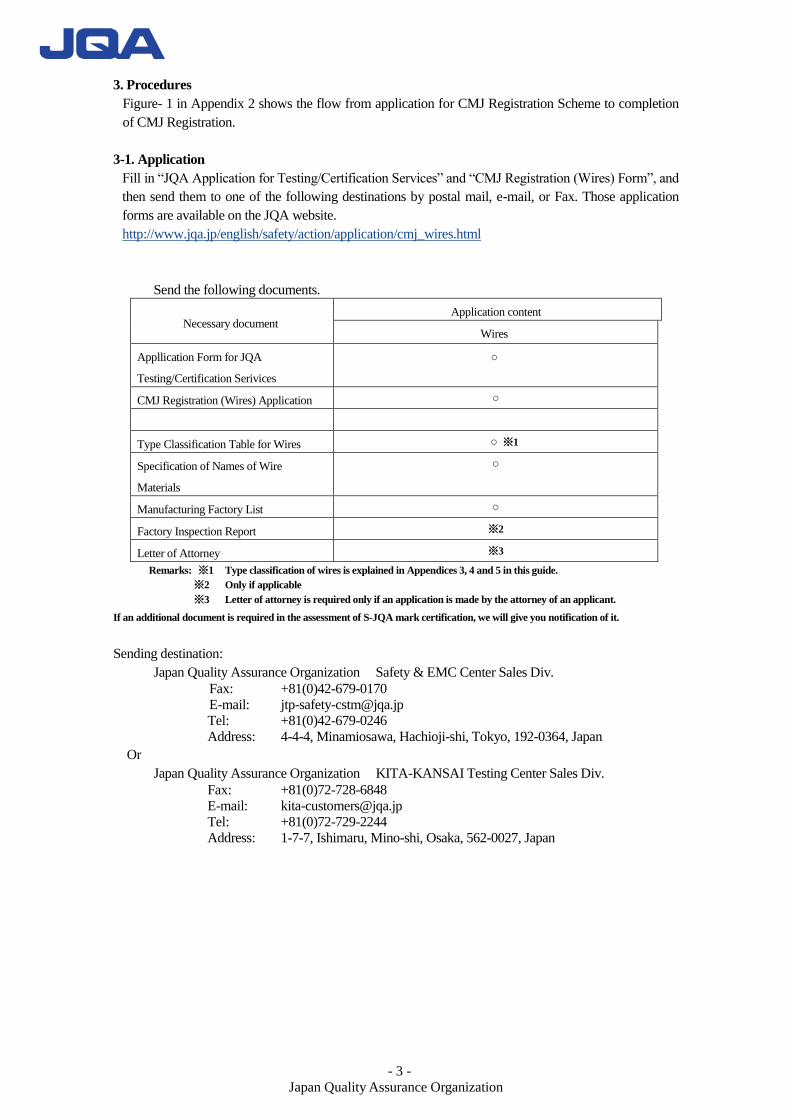
Send the following documents.
Necessary document Application content
Wires
Appllication Form for JQA
Testing/Certification Serivices
○
CMJ Registration (Wires) Application ○
Type Classification Table for Wires ○ ※1
Specification of Names of Wire
Materials
○
Manufacturing Factory List ○
Factory Inspection Report ※2
Letter of Attorney ※3
Remarks: ※1 Type classification of wires is explained in Appendices 3, 4 and 5 in this guide.
※2 Only if applicable
※3 Letter of attorney is required only if an application is made by the attorney of an applicant.
If an additional document is required in the assessment of S-JQA mark certification, we will give you notification of it.
Sending destination:
Japan Quality Assurance Organization Safety & EMC Center Sales Div.
Fax: +81(0)42-679-0170
E-mail: [email protected]
Tel: +81(0)42-679-0246
Address: 4-4-4, Minamiosawa, Hachioji-shi, Tokyo, 192-0364, Japan
Or
Japan Quality Assurance Organization KITA-KANSAI Testing Center Sales Div.
Fax: +81(0)72-728-6848
E-mail: [email protected]
Tel: +81(0)72-729-2244
Address: 1-7-7, Ishimaru, Mino-shi, Osaka, 562-0027, Japan
- 4 -
Japan Quality Assurance Organization
3-2. Testing of Components and Materials and Initial Factory Inspections
(1) Testing of components and materials
Appendix 6 "Testing Standards of Components and Materials That Can be Registered by
Manufacturers and Importers of Components and Materials” shows testing standards for
components and materials that can be registered in JQA. JQA will conduct testing of components
and materials in accordance with the above table. If there is a difference between the above
standards and the applicable standards specified in the application form, JQA will give you
notification of it.
If non-conformities to applicable standards are found during testing of components and materials,
JQA will notify the applicant of the non-conformities. If the applicant receives a report of
non-conformities, the applicant will verify the content and then take corresponding actions such
as taking corrective actions and withdrawing such application, etc. within a given period.
(2) Initial factory inspections
Factories that are not registered in CMJ Registration scheme must be assessed via the CENELEC
method (factory inspection method employed by European bodies) to determine whether products
are manufactured under an appropriate quality control system.
If the initial factory inspection reveals non-conformities to requirements, JQA will conduct
necessary inspections again after an application for improvement is made.
(3) Routine factory inspection
Routine factory inspection is conducted annually to verify that registered products
are adequately manufactured in compliance with the requirements of Optional
Registration System for components and Materials used in Electrical Appliances
(CMJ). This is conducted by visiting only.
Details:Verification that the quality control system checked during the pre-license
factory inspection is maintained and that changes to the control system, if any, are
adequate, and testing on selected samples of registered products.
If unsatisfactory findings that require corrective action are made during the inspection,
repeat inspection is conducted, if corrective action cannot be confirmed, registration may be
cancelled.
(3)-1 Sample selection for testing
During Routine Factory Inspections, samples are in principle selected randomly
from 10% of the number of registered series (rounded off) for flammability test.
In the case of registration including high-voltage dielectric strength test, samples
are selected for each series for high-voltage dielectric strength test.
If samples of registered series are not available during factory inspections, due to
small production etc., they can be selected from samples for quality control test or in
stock, produced after the last factory inspection. Such samples must be kept in an
environment that will not affect the quality of the wire.
(3)-2 Number of samples to be selected
For flammability test: Three samples at length of 50cm per series
For high-voltage dielectric strength test : One sample at length of 5m per series
(Only for registration including high-voltage dielectric strength test)
- 5 -
Japan Quality Assurance Organization
3-3. Conclusion of Contract
A contract for CMJ Registration scheme will be concluded.
3-4. Determination of registration
After validating the results of testing of components and materials and initial factory inspections, JQA
certification implementation division will determine CMJ registration.
3-5. Issuing of Registration Certificate
If there is deemed to be conformity in the determination of registration, JQA will issue the registration
certificate. The registration certificate will be sent together with an invoice for costs incurred in the
application
*Modification or withdrawn of application
If you modify or withdraw an application after acceptance, inform us accordingly.
4. Indication on CMJ-Registered Components and Materials
“CMJ Mark” is a mark indicated as a proof of registration in accordance with CMJ Registration scheme
on the component or a material by the registrant. See Appendix 7 “CMJ Mark” for details on the
indication.
5. Rights and Duties of CMJ Registrants
CMJ registrants may manufacture and ship components and materials that carry the CMJ mark.
Maintaining the registration requires annual maintenance costs, and requires periodical factory
inspection and sampling testing once a year.
If a CMJ-registered product causes an accident or trouble in the market, report to JQA about that
condition. For other rights and duties of CMJ registrants, refer to the contract.
6. Suspension, Cancellation or Termination of CMJ Registration
The registration will be suspended, canceled or terminated in the following cases.
JQA will notify the registrant in writing prior to the implementation:
(1) When requirements (e.g., conformity with technical standards) for continuous registration are not
met.
(2) When the registrant has failed to report the necessary information (e.g., modification of components,
materials or factory), or has provided false report;
(3) When the registrant has used the CMJ mark even though the registration was canceled;
(4) When the registrant indicates CMJ marks on components and materials other than registered ones;
(5) When the registrant has breached the performance of a contract clause, and has failed to correct the
breach despite reminder.
7. Costs
Costs consist of the following items.
(1) Registration fee
This is the basic service cost of applications for new registration (series) and registration
modification (series).See Appendix 8 for classifications of series.
(2) Testing fee
This is the cost of testing of components and materials. (Validation fee for utilizing testing data is
also included.)
- 6 -
Japan Quality Assurance Organization
(3) Initial factory inspection fee
This is the cost of the initial inspection of factories manufacturing components and materials.
(4) Travel cost of business trip
This is the cost of travel for on-site assessment. This is calculated in accordance with JQA
regulations.
(5) Registration maintenance cost
This is the cost of registration maintenance for one year (April 1 to March 31).
Registration maintenance cost is: Registration maintenance base cost + Periodical factory
inspection fee + Sampling testing fee.
(a) Registration maintenance base cost is calculated by the number of series for registered
components and materials, and is charged at the beginning of every fiscal year.
(b) Periodical factory inspection fee
This is the cost of visiting inspection in the registered factory. The cost is charged after the
visiting inspection every year.
(c) Sampling testing fee
This is the cost of sampling test of components and materials. Sampling is performed when
visiting the factory every year.
The cost is charged together with the periodical factory inspection fee.
Examples of costs
(1) Initial application for CMJ registration (New application)
Registration fee + Testing fee + Travel cost of business trip
(2) Application for modification
Registration fee + Testing fee
(3) Application for withdrawal of all registration
Free of charge (This cost is included in the registration maintenance cost)
(4) Registration Maintenance of registration
Registration Maintenance base cost + Periodical factory inspection fee + Travel cost of business
trip + Sampling testing fee
Contact information:
Japan Quality Assurance Organization Safety & EMC Center Sales Div.
Fax: +81(0)42-679-0170
E-mail: [email protected]
Tel: +81(0)42-679-0246
Address: 4-4-4, Minamiosawa, Hachioji-shi, Tokyo, 192-0364, Japan
Or
Japan Quality Assurance Organization KITA-KANSAI Testing Center Sales Div.
Fax: +81(0)72-728-6848
E-mail: [email protected]
Tel: +81(0)72-729-2244
Address: 1-7-7, Ishimaru, Mino-shi, Osaka, 562-0027, Japan
- 7 -
Japan Quality Assurance Organization
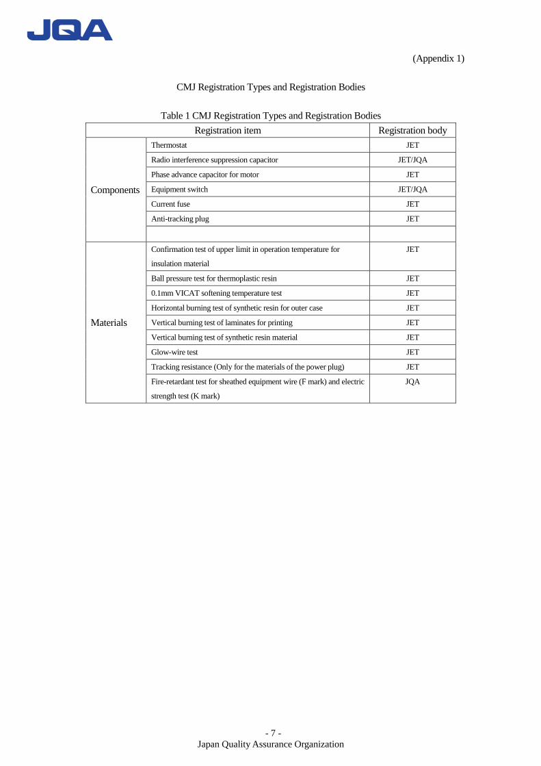
(Appendix 1)
CMJ Registration Types and Registration Bodies
Table 1 CMJ Registration Types and Registration Bodies
Registration item Registration body
Components
Thermostat JET
Radio interference suppression capacitor JET/JQA
Phase advance capacitor for motor JET
Equipment switch JET/JQA
Current fuse JET
Anti-tracking plug JET
Materials
Confirmation test of upper limit in operation temperature for
insulation material
JET
Ball pressure test for thermoplastic resin JET
0.1mm VICAT softening temperature test JET
Horizontal burning test of synthetic resin for outer case JET
Vertical burning test of laminates for printing JET
Vertical burning test of synthetic resin material JET
Glow-wire test JET
Tracking resistance (Only for the materials of the power plug) JET
Fire-retardant test for sheathed equipment wire (F mark) and electric
strength test (K mark)
JQA
- 8 -
Japan Quality Assurance Organization
(Appendix 2)
Figure- 1
Coordination of factory
inspection date
Receipt of factory inspection
date
Implementation of testing
of components and
materials
Implementation of factory
inspection date
Application
Verification against feasible range
Receipt of application form and
documentation
Acceptance of factory
inspection date
Consideration of factory
inspection date
Receipt of acceptance
notice
Confirmation of application content
Sending of acceptance notice
Conclusion of contract
Determination of registration
Sending of deliverables and invoice
Receipt
Signing of contract
Receipt
Payment of costs
Receipt
Applicant
Flowchart to Receipt of CMJ Registration Certificate
Notification of rejection
(Request of missing document)
(Requested document)
Application form
and document
Registration
certificate, contract,
cost invoice
Notification of application
acceptance and estimation
Replying of
inspection date
Notification of inspection
implementation
Receipt of additional document request
Submission of requested document
- 9 -
Japan Quality Assurance Organization
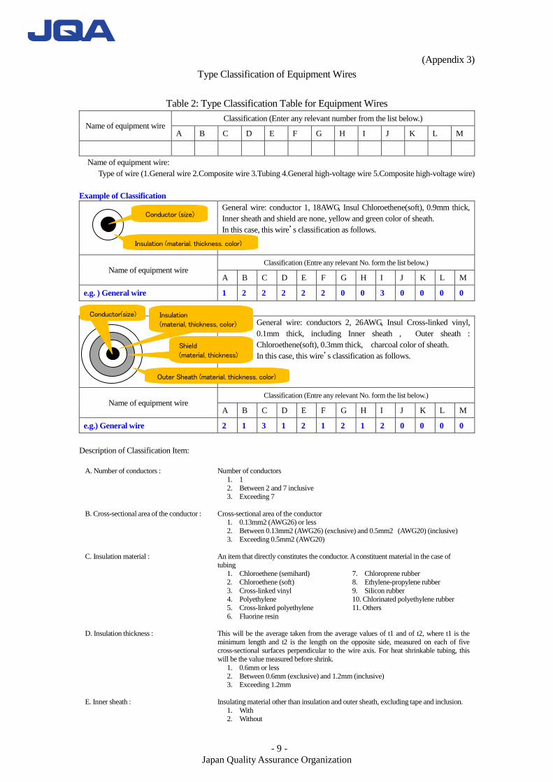
(Appendix 3)
Type Classification of Equipment Wires
Table 2: Type Classification Table for Equipment Wires
Name of equipment wire Classification (Enter any relevant number from the list below.)
A B C D E F G H I J K L M
Name of equipment wire:
Type of wire (1.General wire 2.Composite wire 3.Tubing 4.General high-voltage wire 5.Composite high-voltage wire)
Example of Classification
General wire: conductor 1, 18AWG, Insul Chloroethene(soft), 0.9mm thick,
Inner sheath and shield are none, yellow and green color of sheath.
In this case, this wire’s classification as follows.
Name of equipment wire Classification (Entre any relevant No. form the list below.)
A B C D E F G H I J K L M
e.g. ) General wire 1 2 2 2 2 2 0 0 3 0 0 0 0
General wire: conductors 2, 26AWG, Insul Cross-linked vinyl,
0.1mm thick, including Inner sheath , Outer sheath :
Chloroethene(soft), 0.3mm thick, charcoal color of sheath.
In this case, this wire’s classification as follows.
Name of equipment wire Classification (Entre any relevant No. form the list below.)
A B C D E F G H I J K L M
e.g.) General wire 2 1 3 1 2 1 2 1 2 0 0 0 0
Description of Classification Item:
A. Number of conductors : Number of conductors
1. 1
2. Between 2 and 7 inclusive 3. Exceeding 7
B. Cross-sectional area of the conductor : Cross-sectional area of the conductor 1. 0.13mm2 (AWG26) or less
2. Between 0.13mm2 (AWG26) (exclusive) and 0.5mm2 (AWG20) (inclusive)
3. Exceeding 0.5mm2 (AWG20)
C. Insulation material : An item that directly constitutes the conductor. A constituent material in the case of
tubing
1. Chloroethene (semihard)
2. Chloroethene (soft)
3. Cross-linked vinyl 4. Polyethylene
5. Cross-linked polyethylene
6. Fluorine resin
7. Chloroprene rubber
8. Ethylene-propylene rubber
9. Silicon rubber 10. Chlorinated polyethylene rubber
11. Others
D. Insulation thickness : This will be the average taken from the average values of t1 and of t2, where t1 is the
minimum length and t2 is the length on the opposite side, measured on each of five cross-sectional surfaces perpendicular to the wire axis. For heat shrinkable tubing, this
will be the value measured before shrink.
1. 0.6mm or less 2. Between 0.6mm (exclusive) and 1.2mm (inclusive)
3. Exceeding 1.2mm
E. Inner sheath : Insulating material other than insulation and outer sheath, excluding tape and inclusion.
1. With 2. Without
Conductor (size)
Insulation (material, thickness, color)
Insulation (material, thickness, color)
Shield (material, thickness)
Outer Sheath (material, thickness, color)
Conductor(size)
- 10 -
Japan Quality Assurance Organization
F. Shield : Object provided to shield the influence of electric field and magnetic field.
1. With
2. Without
G. Outer sheath material : Insulating material at outermost jacket, with double or more sheathed.
0. N/A 1. Chloroethene (semihard)
2. Chloroethene (soft)
3. Cross-linked vinyl 4. Polyethylene
5. Cross-linked polyethylene
6. Fluorine resin
7. Chloroprene rubber 8. Ethylene-propylene rubber
9. Silicon rubber
10. Chlorinated polyethylene rubber 11. Glass braid(*1)
12. Others
H. Outer sheath thickness : Thickness of the outermost sheath
0. N/A 1. 0.6mm or less
2. Between 0.6mm (exclusive) and 1.2mm (inclusive)
3. Exceeding 1.2mm
I. Color of outermost material : The color of the outermost sheath for double or more sheathed wire, and the color of
insulation for other wires. Colors of characters, symbols, etc. printed on the surface are not included.
1. Light color ((semi-)transparent, white, yellow, grey, pink,
sky blue (light blue), red, orange, bright green) 2. Dark color (black, charcoal, dark brown, blue, purple, green, brown)
3. Mixed color (*2)
J. Outer diameter : For a wire with round cross-section, this will be an average of values directly measured at
Two points on the same plane perpendicular to the wire axis. For other wires, this will be
long diameter of the same plane perpendicular to the wire axis. 0. N/A
1. 6mm or less
2. Between 6mm (exclusive) and 12mm (inclusive) 3. Exceeding 12mm
K. Inner diameter/dimension : This will be the average of values measured at two or more points in a longitudinal direction of tubing. For heat shrinkable tubing, this will be the average of values
measured before shrink.
0. N/A 1. 3mm or less
2. Between 3mm (exclusive) and 6mm (inclusive)
3. Between 6mm(exclusive) and 10mm (inclusive) 4. 10mm or more
L. Outer diameter of high-voltage cable : Outer diameter of cable 0. N/A
1. 3.82mm or less
2. Between 3.82mm (exclusive) and 5.08mm (inclusive) 3. Exceeding 5.08mm
M. Maximum voltage of high-voltage cable : Maximum voltage of cable 0. N/A
1. Between 2.5kV and 10kV inclusive 2. Between 10kV (exclusive) and 40kV (inclusive)
3. Exceeding 40kV
- 11 -
Japan Quality Assurance Organization
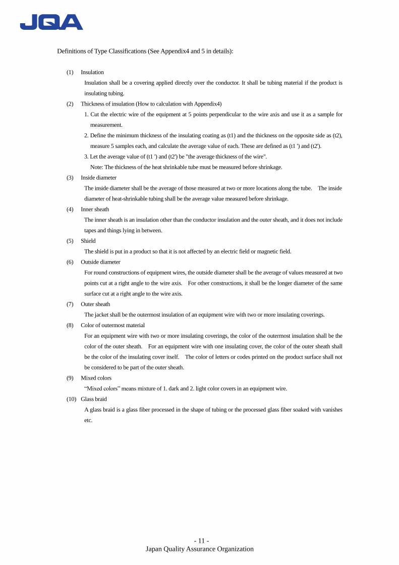
Definitions of Type Classifications (See Appendix4 and 5 in details):
(1) Insulation
Insulation shall be a covering applied directly over the conductor. It shall be tubing material if the product is
insulating tubing.
(2) Thickness of insulation (How to calculation with Appendix4)
1. Cut the electric wire of the equipment at 5 points perpendicular to the wire axis and use it as a sample for
measurement.
2. Define the minimum thickness of the insulating coating as (t1) and the thickness on the opposite side as (t2),
measure 5 samples each, and calculate the average value of each. These are defined as (t1 ') and (t2').
3. Let the average value of (t1 ') and (t2') be "the average thickness of the wire".
Note: The thickness of the heat shrinkable tube must be measured before shrinkage.
(3) Inside diameter
The inside diameter shall be the average of those measured at two or more locations along the tube. The inside
diameter of heat-shrinkable tubing shall be the average value measured before shrinkage.
(4) Inner sheath
The inner sheath is an insulation other than the conductor insulation and the outer sheath, and it does not include
tapes and things lying in between.
(5) Shield
The shield is put in a product so that it is not affected by an electric field or magnetic field.
(6) Outside diameter
For round constructions of equipment wires, the outside diameter shall be the average of values measured at two
points cut at a right angle to the wire axis. For other constructions, it shall be the longer diameter of the same
surface cut at a right angle to the wire axis.
(7) Outer sheath
The jacket shall be the outermost insulation of an equipment wire with two or more insulating coverings.
(8) Color of outermost material
For an equipment wire with two or more insulating coverings, the color of the outermost insulation shall be the
color of the outer sheath. For an equipment wire with one insulating cover, the color of the outer sheath shall
be the color of the insulating cover itself. The color of letters or codes printed on the product surface shall not
be considered to be part of the outer sheath.
(9) Mixed colors
“Mixed colors” means mixture of 1. dark and 2. light color covers in an equipment wire.
(10) Glass braid
A glass braid is a glass fiber processed in the shape of tubing or the processed glass fiber soaked with vanishes
etc.
- 12 -
Japan Quality Assurance Organization
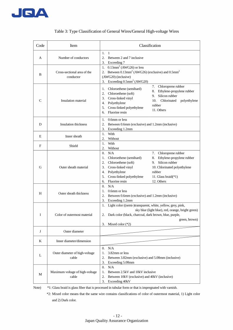
Table 3: Type Classification of General Wires/General High-voltage Wires
Code Item Classification
A Number of conductors
1. 1
2. Between 2 and 7 inclusive
3. Exceeding 7
B Cross-sectional area of the
conductor
1. 0.13mm2 (AWG26) or less
2. Between 0.13mm2 (AWG26) (exclusive) and 0.5mm2
(AWG20) (inclusive)
3. Exceeding 0.5mm2 (AWG20)
C Insulation material
1. Chloroethene (semihard)
2. Chloroethene (soft)
3. Cross-linked vinyl
4. Polyethylene
5. Cross-linked polyethylene
6. Fluorine resin
7. Chloroprene rubber
8. Ethylene-propylene rubber
9. Silicon rubber
10. Chlorinated polyethylene
rubber
11. Others
D Insulation thickness
1. 0.6mm or less
2. Between 0.6mm (exclusive) and 1.2mm (inclusive)
3. Exceeding 1.2mm
E Inner sheath 1. With
2. Without
F Shield 1. With
2. Without
G Outer sheath material
0. N/A
1. Chloroethene (semihard)
2. Chloroethene (soft)
3. Cross-linked vinyl
4. Polyethylene
5. Cross-linked polyethylene
6. Fluorine resin
7. Chloroprene rubber
8. Ethylene-propylene rubber
9. Silicon rubber
10. Chlorinated polyethylene
rubber
11. Glass braid(*1)
12. Others
H Outer sheath thickness
0. N/A
1. 0.6mm or less
2. Between 0.6mm (exclusive) and 1.2mm (inclusive)
3. Exceeding 1.2mm
I Color of outermost material
1. Light color ((semi-)transparent, white, yellow, grey, pink,
sky blue (light blue), red, orange, bright green)
2. Dark color (black, charcoal, dark brown, blue, purple,
green, brown)
3. Mixed color (*2)
J Outer diameter
K Inner diameter/dimension
L Outer diameter of high-voltage
cable
0. N/A
1. 3.82mm or less
2. Between 3.82mm (exclusive) and 5.08mm (inclusive)
3. Exceeding 5.08mm
M Maximum voltage of high-voltage
cable
0. N/A
1. Between 2.5kV and 10kV inclusive
2. Between 10kV (exclusive) and 40kV (inclusive)
3. Exceeding 40kV
Note) *1: Glass braid is glass fiber that is processed in tubular form or that is impregnated with varnish.
*2: Mixed color means that the same wire contains classifications of color of outermost material, 1) Light color
and 2) Dark color.
- 13 -
Japan Quality Assurance Organization
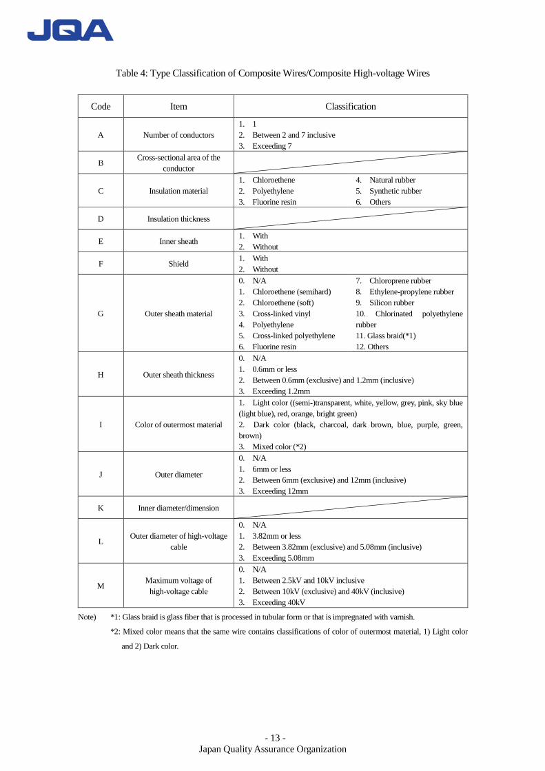
Table 4: Type Classification of Composite Wires/Composite High-voltage Wires
Code Item Classification
A Number of conductors
1. 1
2. Between 2 and 7 inclusive
3. Exceeding 7
B Cross-sectional area of the
conductor
C Insulation material
1. Chloroethene
2. Polyethylene
3. Fluorine resin
4. Natural rubber
5. Synthetic rubber
6. Others
D Insulation thickness
E Inner sheath 1. With
2. Without
F Shield 1. With
2. Without
G Outer sheath material
0. N/A
1. Chloroethene (semihard)
2. Chloroethene (soft)
3. Cross-linked vinyl
4. Polyethylene
5. Cross-linked polyethylene
6. Fluorine resin
7. Chloroprene rubber
8. Ethylene-propylene rubber
9. Silicon rubber
10. Chlorinated polyethylene
rubber
11. Glass braid(*1)
12. Others
H Outer sheath thickness
0. N/A
1. 0.6mm or less
2. Between 0.6mm (exclusive) and 1.2mm (inclusive)
3. Exceeding 1.2mm
I Color of outermost material
1. Light color ((semi-)transparent, white, yellow, grey, pink, sky blue
(light blue), red, orange, bright green)
2. Dark color (black, charcoal, dark brown, blue, purple, green,
brown)
3. Mixed color (*2)
J Outer diameter
0. N/A
1. 6mm or less
2. Between 6mm (exclusive) and 12mm (inclusive)
3. Exceeding 12mm
K Inner diameter/dimension
L Outer diameter of high-voltage
cable
0. N/A
1. 3.82mm or less
2. Between 3.82mm (exclusive) and 5.08mm (inclusive)
3. Exceeding 5.08mm
M Maximum voltage of
high-voltage cable
0. N/A
1. Between 2.5kV and 10kV inclusive
2. Between 10kV (exclusive) and 40kV (inclusive)
3. Exceeding 40kV
Note) *1: Glass braid is glass fiber that is processed in tubular form or that is impregnated with varnish.
*2: Mixed color means that the same wire contains classifications of color of outermost material, 1) Light color
and 2) Dark color.
- 14 -
Japan Quality Assurance Organization
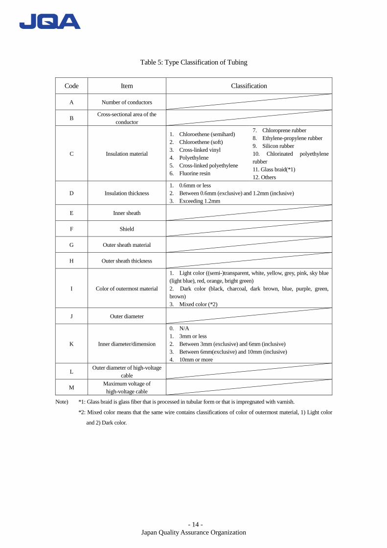
Table 5: Type Classification of Tubing
Code Item Classification
A Number of conductors
B Cross-sectional area of the
conductor
C Insulation material
1. Chloroethene (semihard)
2. Chloroethene (soft)
3. Cross-linked vinyl
4. Polyethylene
5. Cross-linked polyethylene
6. Fluorine resin
7. Chloroprene rubber
8. Ethylene-propylene rubber
9. Silicon rubber
10. Chlorinated polyethylene
rubber
11. Glass braid(*1)
12. Others
D Insulation thickness
1. 0.6mm or less
2. Between 0.6mm (exclusive) and 1.2mm (inclusive)
3. Exceeding 1.2mm
E Inner sheath
F Shield
G Outer sheath material
H Outer sheath thickness
I Color of outermost material
1. Light color ((semi-)transparent, white, yellow, grey, pink, sky blue
(light blue), red, orange, bright green)
2. Dark color (black, charcoal, dark brown, blue, purple, green,
brown)
3. Mixed color (*2)
J Outer diameter
K Inner diameter/dimension
0. N/A
1. 3mm or less
2. Between 3mm (exclusive) and 6mm (inclusive)
3. Between 6mm(exclusive) and 10mm (inclusive)
4. 10mm or more
L Outer diameter of high-voltage
cable
M Maximum voltage of
high-voltage cable
Note) *1: Glass braid is glass fiber that is processed in tubular form or that is impregnated with varnish.
*2: Mixed color means that the same wire contains classifications of color of outermost material, 1) Light color
and 2) Dark color.
- 15 -
Japan Quality Assurance Organization
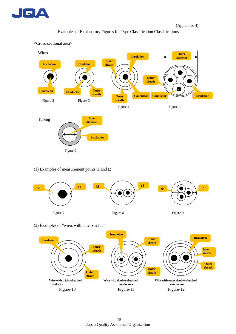
(Appendix 4)
Examples of Explanatory Figures for Type Classification Classifications
<Cross-sectional area> Wires
Figure-2 Figure-3
Figure-4 Figure-5
Tubing
Figure-6
(1) Examples of measurement points t1 and t2
Figure-7 Figure-8 Figure-9
(2) Examples of “wires with inner sheath”
Wire with triply-sheathed Wire with double-sheathed Wire with outer double-sheathed
conductor conductors conductors
Figure-10 Figure-11 Figure-12
Insulation
Inner
sheath
Outer
sheath
Insulation Insulation
Inner
sheath
Outer
sheath
Insulation Insulation
Insulation
Insulation
Insulation
Conductor Conductor
Conductor Conductor
Inner
sheath
Outer
sheath Outer
sheath
Outer
sheath
Outer
diameter
Inner
sheath
Outer
sheath
Inner
diameter
t1 t2 t1 t2 t1
1 t2
- 16 -
Japan Quality Assurance Organization
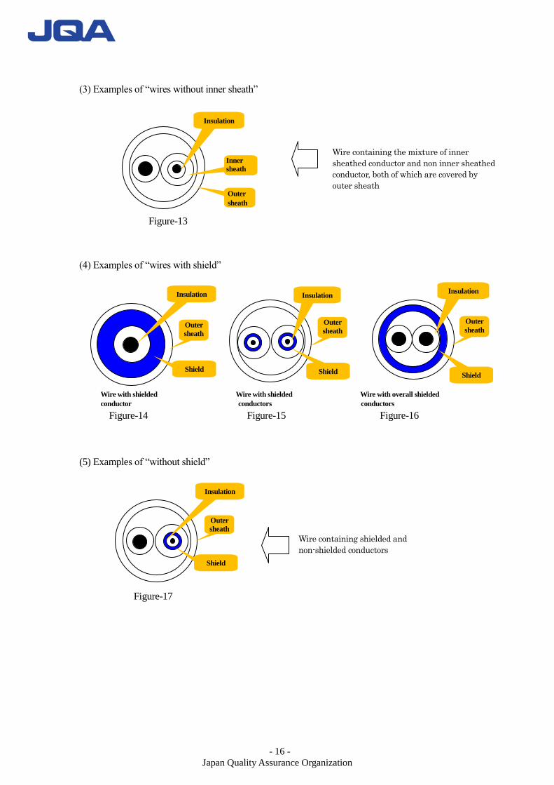
(3) Examples of “wires without inner sheath”
Figure-13
(4) Examples of “wires with shield”
Wire with shielded Wire with shielded Wire with overall shielded
conductor conductors conductors
Figure-14 Figure-15 Figure-16
(5) Examples of “without shield”
Figure-17
Wire containing the mixture of inner
sheathed conductor and non inner sheathed
conductor, both of which are covered by
outer sheath
Wire containing shielded and
non-shielded conductors
Insulation
Insulation
Inner
sheath
Outer
sheath
Outer
sheath
Shield
Insulation
Outer
sheath
Shield
Insulation
Outer
sheath
Shield
Insulation
Outer
sheath
Shield

- 17 -
Japan Quality Assurance Organization
(Appendix 5)
Classification of General Wires and Composite Wires
1. General wire refers to either of the following category a or b.
a. Wires with single conductor
b. Wires with multiple conductors as shown below.
(1) Wires with outer sheath (Fig. 17)
Wires classified under the following category A or B and have the same classification in
the type classifications of general wires where the wires are classified by cross-sectional
area of the conductor, insulation material, insulation thickness, inner sheath, shield, outer
sheath material, and outer sheath thickness out of type classification items for general
wire.
A. Respective wires with the coverall outer sheath removed (Fig. 17a)
B. Respective wires with any inner sheath covering wires (if any) removed
after the overall sheath covering the individual wires is removed (Fig. 17b)
Figure-18 Figure-18a Figure-18b
(2) Wires without outer sheath (Figure- 18)
Each of the wires (A, B, C and D in Figure- 18) with the same classifications in the type
classification of general wires where the wires are classified by cross-sectional area of
the conductor, insulation material, insulation thickness, inner sheath, shield, outer sheath
material, and outer sheath thickness out of type classification items for general wire.
A B C D
Figure-19
2. Composite wire refers to a wire other than general wires and tubing.
Figure-20 Figure-21 Figure-22
- 18 -
Japan Quality Assurance Organization
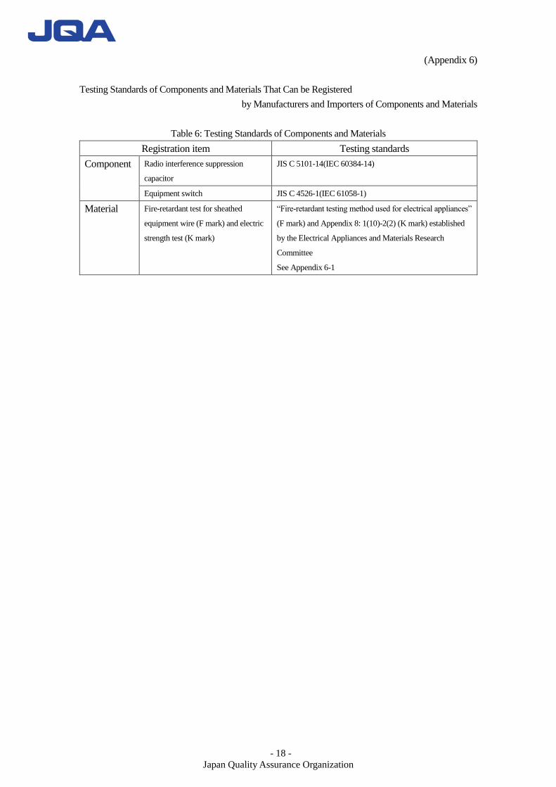
(Appendix 6)
Testing Standards of Components and Materials That Can be Registered
by Manufacturers and Importers of Components and Materials
Table 6: Testing Standards of Components and Materials
Registration item Testing standards
Component Radio interference suppression
capacitor
JIS C 5101-14(IEC 60384-14)
Equipment switch JIS C 4526-1(IEC 61058-1)
Material Fire-retardant test for sheathed
equipment wire (F mark) and electric
strength test (K mark)
“Fire-retardant testing method used for electrical appliances”
(F mark) and Appendix 8: 1(10)-2(2) (K mark) established
by the Electrical Appliances and Materials Research
Committee
See Appendix 6-1
- 19 -
Japan Quality Assurance Organization
(Appendix6-1)
Method for Flammability Test on Equipment Wires Under Optional Registration System for
Components and Materials used in Electrical Appliance (CMJ).
1. Objectives
This testing method is designed to confirm the safety against flammability of built-in insulation wires
for use in television receivers, electronics-based toys and other electronics-based playing appliances
under the CMJ.
2. Testing equipment
In principle, tests shall be conducted at a no-wind site with the ranges of room temperature 15-35℃,
humidity 45-75% RH, atmospheric pressure 860-1,060m bar.
3. Testing unit
(1) Testing box
About 310mm wide, 360mm deep and 610mm high metal box with its top and front open.
(2) Testing burner
Bunsen or tirrill burner with inside diameter.
Above 8.5mm but below 11.5mm and with a 100 ± 10mm long tube.
(3) Testing gas
Gas of about 1000 BTU/ft3 or No.
C gas specified in JIS K2240 (1982) “Liquefied Petroleum (LP) Gas”.
(4) Stand
Stand provided with clamps or any other equivalent units capable of vertically holding a
specimen.
(5) Display flag
One equivalent to class 2 No.1 specified in JIS Z1511 (1975) “Paper Gum Tapes (For
Packaging).
(6) Stopwatch or other clock unit
(7) Dry absorbent cotton
- 20 -
Japan Quality Assurance Organization
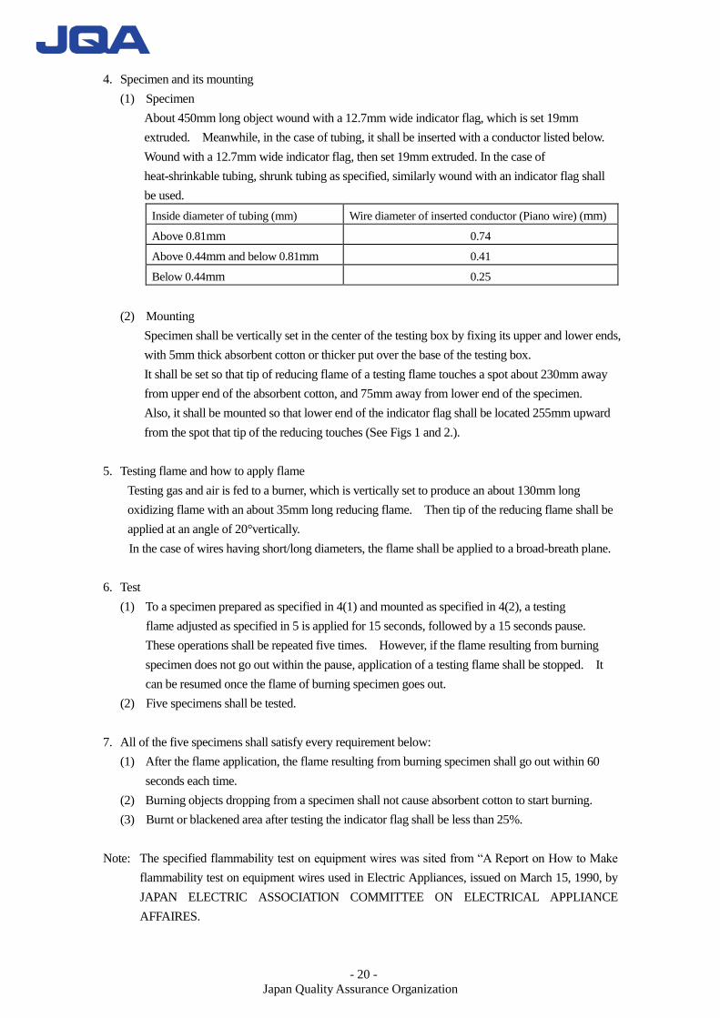
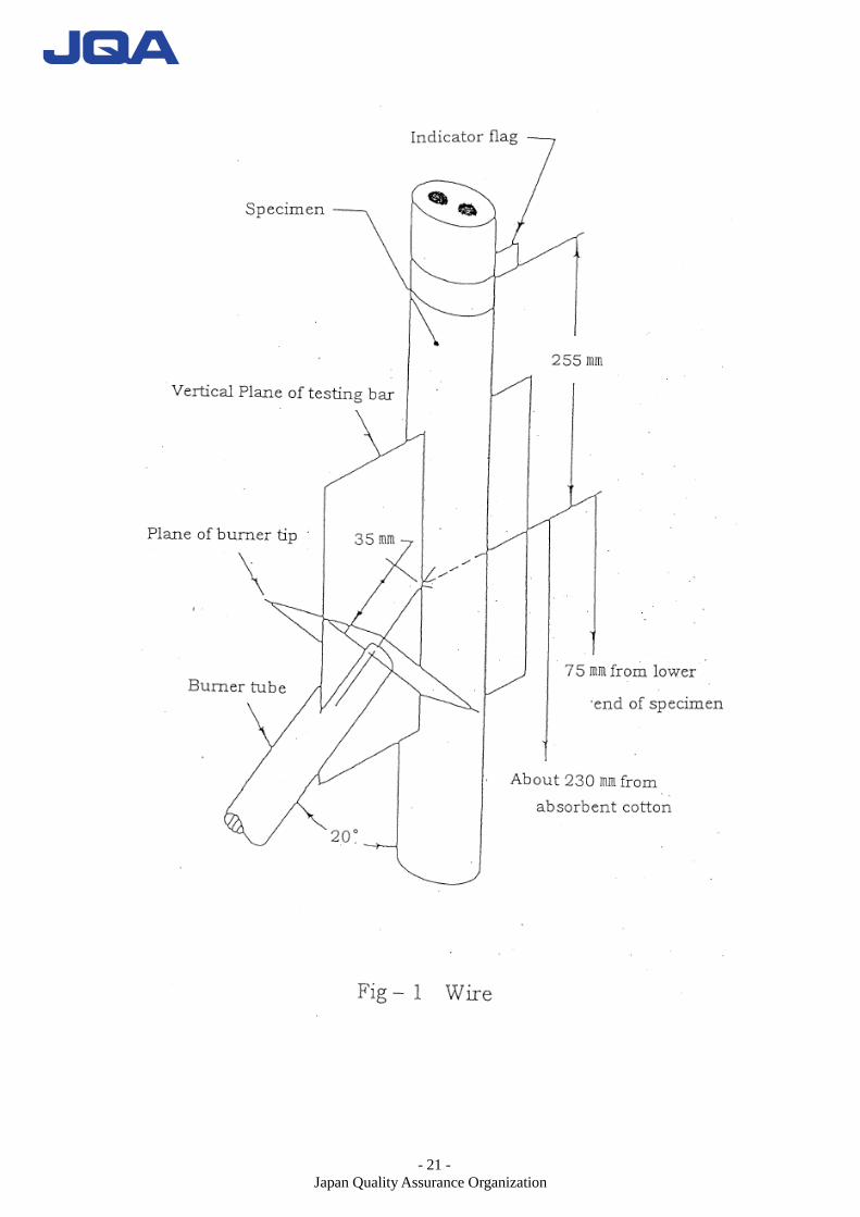
4. Specimen and its mounting
(1) Specimen
About 450mm long object wound with a 12.7mm wide indicator flag, which is set 19mm
extruded. Meanwhile, in the case of tubing, it shall be inserted with a conductor listed below.
Wound with a 12.7mm wide indicator flag, then set 19mm extruded. In the case of
heat-shrinkable tubing, shrunk tubing as specified, similarly wound with an indicator flag shall
be used.
Inside diameter of tubing (mm) Wire diameter of inserted conductor (Piano wire) (mm)
Above 0.81mm 0.74
Above 0.44mm and below 0.81mm 0.41
Below 0.44mm 0.25
(2) Mounting
Specimen shall be vertically set in the center of the testing box by fixing its upper and lower ends,
with 5mm thick absorbent cotton or thicker put over the base of the testing box.
It shall be set so that tip of reducing flame of a testing flame touches a spot about 230mm away
from upper end of the absorbent cotton, and 75mm away from lower end of the specimen.
Also, it shall be mounted so that lower end of the indicator flag shall be located 255mm upward
from the spot that tip of the reducing touches (See Figs 1 and 2.).
5. Testing flame and how to apply flame
Testing gas and air is fed to a burner, which is vertically set to produce an about 130mm long
oxidizing flame with an about 35mm long reducing flame. Then tip of the reducing flame shall be
applied at an angle of 20°vertically.
In the case of wires having short/long diameters, the flame shall be applied to a broad-breath plane.
6. Test
(1) To a specimen prepared as specified in 4(1) and mounted as specified in 4(2), a testing
flame adjusted as specified in 5 is applied for 15 seconds, followed by a 15 seconds pause.
These operations shall be repeated five times. However, if the flame resulting from burning
specimen does not go out within the pause, application of a testing flame shall be stopped. It
can be resumed once the flame of burning specimen goes out.
(2) Five specimens shall be tested.
7. All of the five specimens shall satisfy every requirement below:
(1) After the flame application, the flame resulting from burning specimen shall go out within 60
seconds each time.
(2) Burning objects dropping from a specimen shall not cause absorbent cotton to start burning.
(3) Burnt or blackened area after testing the indicator flag shall be less than 25%.
Note: The specified flammability test on equipment wires was sited from “A Report on How to Make
flammability test on equipment wires used in Electric Appliances, issued on March 15, 1990, by
JAPAN ELECTRIC ASSOCIATION COMMITTEE ON ELECTRICAL APPLIANCE
AFFAIRES.
- 21 -
Japan Quality Assurance Organization
- 22 -
Japan Quality Assurance Organization
- 23 -
Japan Quality Assurance Organization
HOW TO CONDUCT FLAMMABILITY TEST ON EQUIPMENT WIRES
USED IN ELECTRIC APPLIANCES : EXPLANATIONS
Introduction
Discussions were made of testing methods to confirm the safety against flammability of built-in
jacketed wires (including tubes) used in electric appliances (television receivers, electronics-based toys
and other electronics-based playing appliance).
To examine this testing method, difference among representative methods to check flammability of
apparatus - use equipment wires, employed in various countries, are summarized in a “Comparative List
of Vertical Combustion Testing Standards for Equipment Wire Vertical Combustion Testing Standards”.
As for IEC, it is omitted this time because it its in the stage of unification of testing methods and
consideration of approval testing system. However, given the fact that IEC standards are serving as
international testing standards, it appears necessary for us to propose to IEC, not vice versa, ways to deal
with trends likely from now on, as well as this testing methods.
Detailed explanations are given below under each item.
1. Test Equipment
To increase reproducibility of test results, temperature humidity and atmospheric pressure are
specified. The specified figures were taken from the testing conditions for the temperate zone as
specified in IEC standards. Also, the brightness of the testing site and availability of exhaust, the
former necessary for identifying flame, and the latter for protecting testing staff, are not specified this
time, because it is difficult to set forth harmonized specifications.
2. Burner
Existing specifications are adopted because the Electrical Apparatus Safety Law Technical
Requirements are based on various foreign standards. In addition, length of tube taken from UL and
CSA standards is specified.
In the meantime, specifying a testing flame by length could cause human errors to affect test results.
IEC is now considering an international unification of burner requirements in the hope of specifying
the test flame by gas and air flow. Once the unification is realized, this needs to be revised.
- 24 -
Japan Quality Assurance Organization
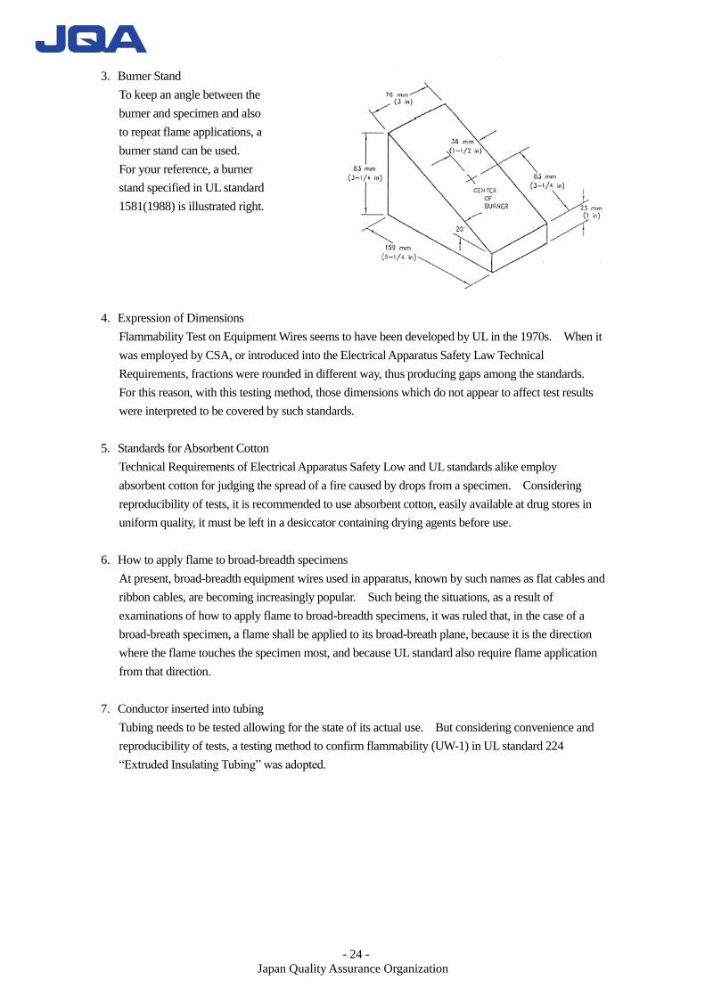
3. Burner Stand
To keep an angle between the
burner and specimen and also
to repeat flame applications, a
burner stand can be used.
For your reference, a burner
stand specified in UL standard
1581(1988) is illustrated right.
4. Expression of Dimensions
Flammability Test on Equipment Wires seems to have been developed by UL in the 1970s. When it
was employed by CSA, or introduced into the Electrical Apparatus Safety Law Technical
Requirements, fractions were rounded in different way, thus producing gaps among the standards.
For this reason, with this testing method, those dimensions which do not appear to affect test results
were interpreted to be covered by such standards.
5. Standards for Absorbent Cotton
Technical Requirements of Electrical Apparatus Safety Low and UL standards alike employ
absorbent cotton for judging the spread of a fire caused by drops from a specimen. Considering
reproducibility of tests, it is recommended to use absorbent cotton, easily available at drug stores in
uniform quality, it must be left in a desiccator containing drying agents before use.
6. How to apply flame to broad-breadth specimens
At present, broad-breadth equipment wires used in apparatus, known by such names as flat cables and
ribbon cables, are becoming increasingly popular. Such being the situations, as a result of
examinations of how to apply flame to broad-breadth specimens, it was ruled that, in the case of a
broad-breath specimen, a flame shall be applied to its broad-breath plane, because it is the direction
where the flame touches the specimen most, and because UL standard also require flame application
from that direction.
7. Conductor inserted into tubing
Tubing needs to be tested allowing for the state of its actual use. But considering convenience and
reproducibility of tests, a testing method to confirm flammability (UW-1) in UL standard 224
“Extruded Insulating Tubing” was adopted.
- 25 -
Japan Quality Assurance Organization
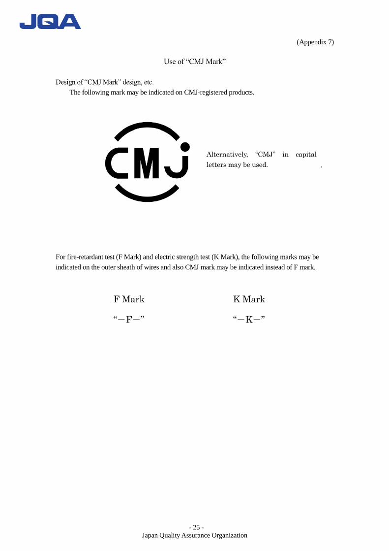
(Appendix 7)
Use of “CMJ Mark”
Design of “CMJ Mark” design, etc.
The following mark may be indicated on CMJ-registered products.
For fire-retardant test (F Mark) and electric strength test (K Mark), the following marks may be
indicated on the outer sheath of wires and also CMJ mark may be indicated instead of F mark.
Alternatively, “CMJ” in capital
letters may be used.
F Mark
“-F-”
K Mark
“-K-”
- 26 -
Japan Quality Assurance Organization
(Appendix 8)
Series Classification of Wires
Table 7: Series Classification of General Wires
Code Item Classification
A Number of conductors
1. 1
2. Between 2 and 7 inclusive
3. Exceeding 7
C Insulation material
1. Chloroethene
2. Polyethylene
3. Fluorine resin
4. Natural rubber
5. Synthetic rubber
6. Others
D Insulation thickness
1. 0.6mm or less
2. Between 0.6mm (exclusive) and 1.2mm (inclusive)
3. Exceeding 1.2mm
F Shield 1. With
2. Without
Table 8: Series Classification of Composite Wires
Code Item Classification
A Number of conductors
1. 1
2. Between 2 and 7 inclusive
3. Exceeding 7
F Shield 1. With
2. Without
G Outer sheath material
1. Chloroethene
2. Polyethylene
3. Fluorine resin
4. Natural rubber
5. Synthetic rubber
6. Glass braid
7. Others
H Outer sheath thickness
1. 0.6mm or less
2. Between 0.6mm (exclusive) and 1.2mm (inclusive)
3. Exceeding 1.2mm
Table 9: Series Classification of Tubing
Code Item Classification
C Insulation material
1. Chloroethene
2. Polyethylene
3. Fluorine resin
4. Natural rubber
5. Synthetic rubber
6. Glass braid
7. Others
D Insulation thickness
1. 0.6mm or less
2. Between 0.6mm (exclusive) and 1.2mm (inclusive)
3. Exceeding 1.2mm
K Internal diameter
1. 3mm or less
2. Between 3mm (exclusive) and 6mm (inclusive)
3. Between 6mm (exclusive) and 10mm (inclusive)
4. 10mm or more
- 27 -
Japan Quality Assurance Organization
Table 10: Series Classification of General High-voltage Wires
Code Item Classification
A Number of conductors
1. 1
2. Between 2 and 7 inclusive
3. Exceeding 7
C Insulation material
1. Chloroethene
2. Polyethylene
3. Fluorine resin
4. Natural rubber
5. Synthetic rubber
6. Others
D Insulation thickness
1. 0.6mm or less
2. Between 0.6mm (exclusive) and 1.2mm (inclusive)
3. Exceeding 1.2mm
F Shield 1. With
2. Without
L External diameter of
high-voltage wire
1. 3.82mm or less
2. Between 3.82mm (exclusive) and 5.08mm (inclusive)
3. Exceeding 5.08mm
Table 11: Series Classification of Composite High-voltage Wires
Code Item Classification
A Number of conductors
1. 1
2. Between 2 and 7 inclusive
3. Exceeding 7
F Shield 1. With
2. Without
G Outer sheath material
1. Chloroethene
2. Polyethylene
3. Fluorine resin
4. Natural rubber
5. Synthetic rubber
6. Glass braid
7. Others
H Outer sheath thickness
1. 0.6mm or less
2. Between 0.6mm (exclusive) and 1.2mm (inclusive)
3. Exceeding 1.2mm
L Outer diameter of high-voltage
cable
1. 3.82mm or less
2. Between 3.82mm (exclusive) and 5.08mm (inclusive)
3. 5.08mm or more