Embed Size (px)
Citation preview
P208 Version 1.1 Page 1 of 1
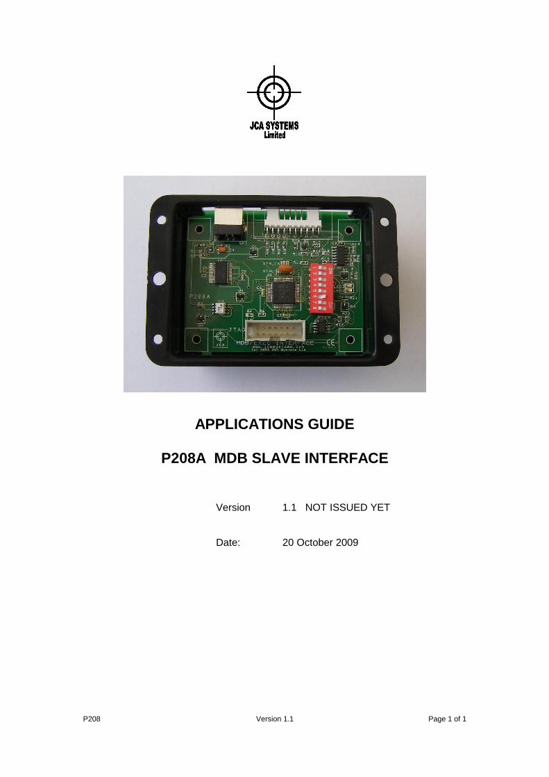
APPLICATIONS GUIDE
P208A MDB SLAVE INTERFACE
Version 1.1 NOT ISSUED YET Date: 20 October 2009
APPLICATIONS GUIDE - P208 MDB INTERFACE
P208 Version 1.1 Page 2 of 2
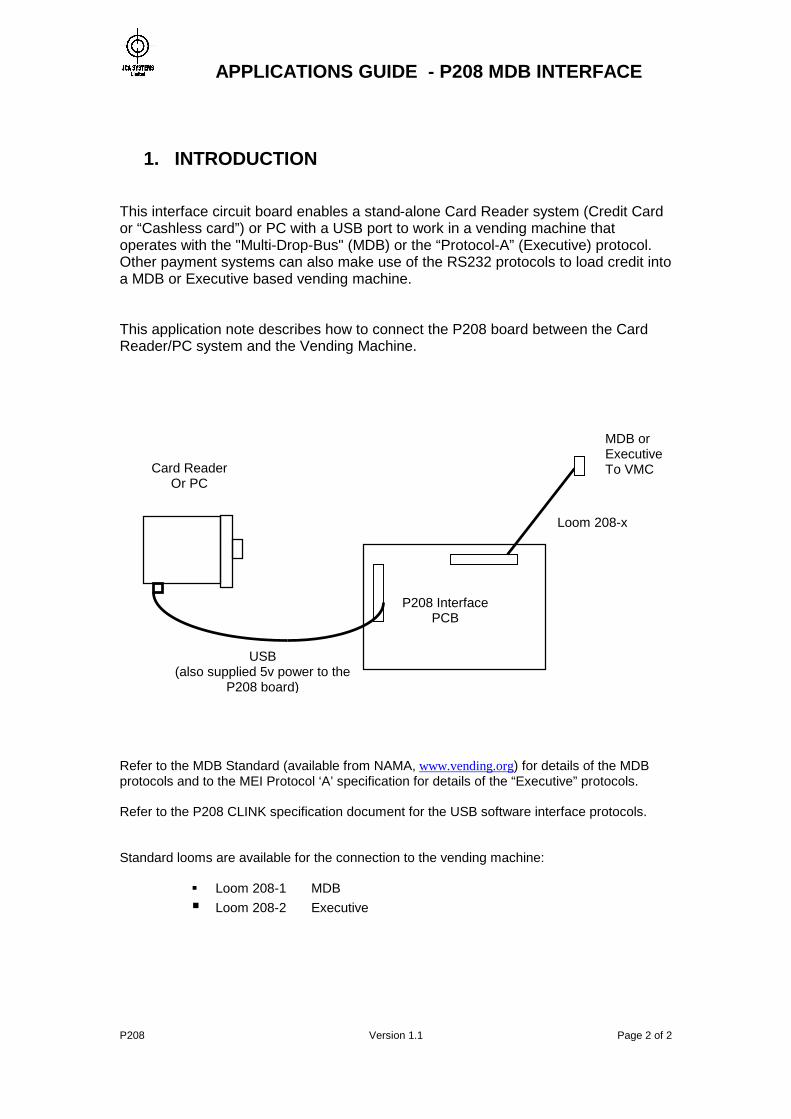
1. INTRODUCTION This interface circuit board enables a stand-alone Card Reader system (Credit Card or “Cashless card”) or PC with a USB port to work in a vending machine that operates with the "Multi-Drop-Bus" (MDB) or the “Protocol-A” (Executive) protocol. Other payment systems can also make use of the RS232 protocols to load credit into a MDB or Executive based vending machine. This application note describes how to connect the P208 board between the Card Reader/PC system and the Vending Machine. Refer to the MDB Standard (available from NAMA, www.vending.org) for details of the MDB protocols and to the MEI Protocol ‘A’ specification for details of the “Executive” protocols. Refer to the P208 CLINK specification document for the USB software interface protocols. Standard looms are available for the connection to the vending machine:
Loom 208-1 MDB Loom 208-2 Executive
Card Reader Or PC
P208 Interface PCB
MDB or Executive To VMC
USB (also supplied 5v power to the
P208 board)
Loom 208-x
APPLICATIONS GUIDE - P208 MDB INTERFACE
P208 Version 1.1 Page 3 of 3
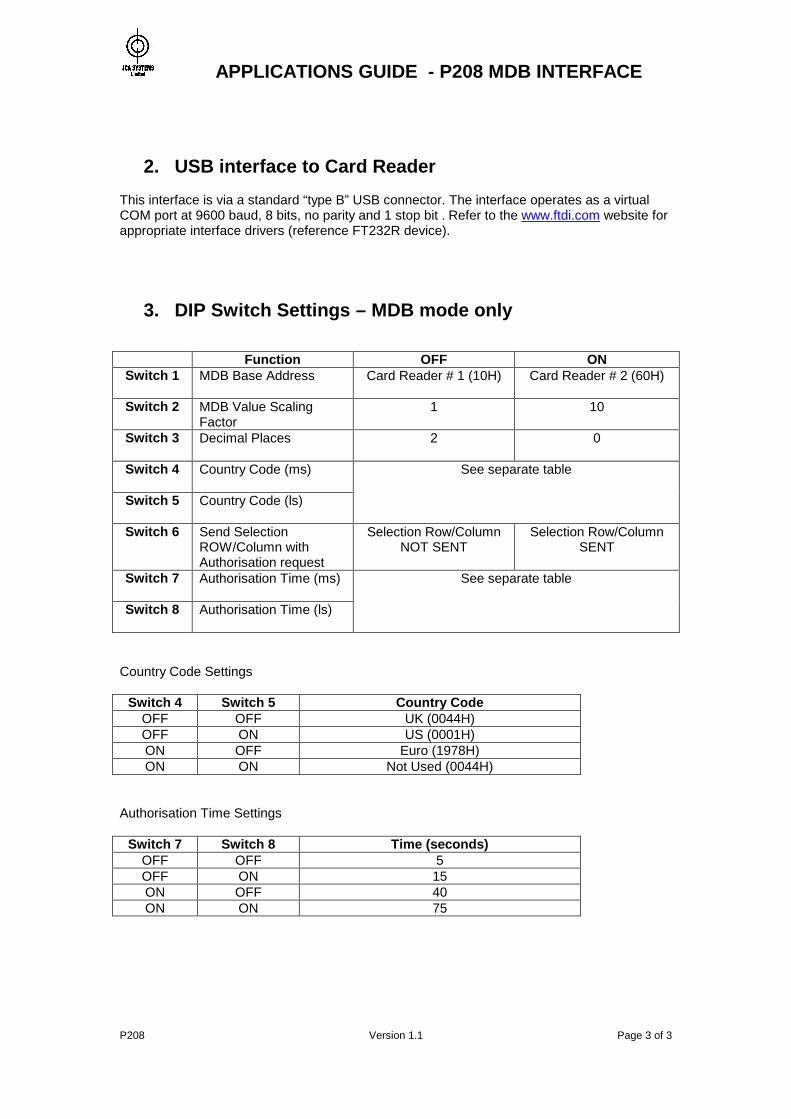
2. USB interface to Card Reader This interface is via a standard “type B” USB connector. The interface operates as a virtual COM port at 9600 baud, 8 bits, no parity and 1 stop bit . Refer to the www.ftdi.com website for appropriate interface drivers (reference FT232R device).
3. DIP Switch Settings – MDB mode only
Function OFF ON Switch 1
MDB Base Address Card Reader # 1 (10H) Card Reader # 2 (60H)
Switch 2 MDB Value Scaling Factor
1 10
Switch 3
Decimal Places 2 0
Switch 4
Country Code (ms)
Switch 5
Country Code (ls)
See separate table
Switch 6
Send Selection ROW/Column with Authorisation request
Selection Row/Column NOT SENT
Selection Row/Column SENT
Switch 7
Authorisation Time (ms)
Switch 8
Authorisation Time (ls)
See separate table
Country Code Settings
Switch 4 Switch 5 Country Code OFF OFF UK (0044H) OFF ON US (0001H) ON OFF Euro (1978H) ON ON Not Used (0044H)
Authorisation Time Settings
Switch 7 Switch 8 Time (seconds) OFF OFF 5 OFF ON 15 ON OFF 40 ON ON 75
APPLICATIONS GUIDE - P208 MDB INTERFACE
P208 Version 1.1 Page 4 of 4
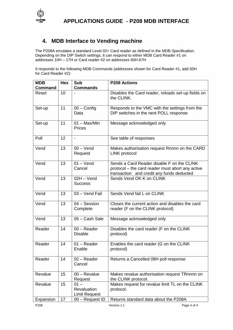
4. MDB Interface to Vending machine The P208A emulates a standard Level 02+ Card reader as defined in the MDB Specification. Depending on the DIP Switch settings, it can respond to either MDB Card Reader #1 on addresses 10H – 17H or Card reader #2 on addresses 60H-67H It responds to the following MDB Commands (addresses shown for Card Reader #1, add 50H for Card Reader #2): MDB Command
Hex Sub Commands
P208 Actions
Reset
10 - Disables the Card reader, reloads set-up fields on the CLINK.
Set-up
11 00 – Config Data
Responds to the VMC with the settings from the DIP switches in the next POLL response
Set-up
11 01 – Max/Min Prices
Message acknowledged only
Poll
12 - See table of responses
Vend
13 00 – Vend Request
Makes authorisation request Rnnnn on the CARD LINK protocol
Vend
13 01 – Vend Cancel
Sends a Card Reader disable F on the CLINK protocol – the card reader must abort any active transaction and credit any funds deducted
Vend
13 02H – Vend Success
Sends Vend OK K on CLINK
Vend
13 03 – Vend Fail Sends Vend fail L on CLINK
Vend
13 04 – Session Complete
Closes the current action and disables the card reader (F on the CLINK protocol)
Vend
13 05 – Cash Sale Message acknowledged only
Reader
14 00 – Reader Disable
Disables the card reader (F on the CLINK protocol)
Reader
14 01 – Reader Enable
Enables the card reader (G on the CLINK protocol)
Reader
14 02 – Reader Cancel
Returns a Cancelled 08H poll response
Revalue 15 00 – Revalue Request
Makes revalue authorisation request TRnnnn on the CLINK protocol.
Revalue 15 01 – Revaluation Limit Request
Makes request for revalue limit TL on the CLINK protocol.
Expansion 17 00 – Request ID Returns standard data about the P208A
APPLICATIONS GUIDE - P208 MDB INTERFACE
P208 Version 1.1 Page 5 of 5
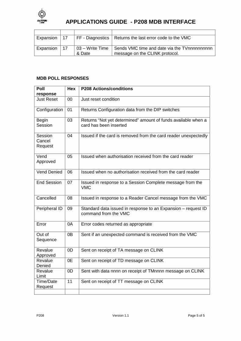
Expansion
17 FF - Diagnostics Returns the last error code to the VMC
Expansion 17 03 – Write Time & Date
Sends VMC time and date via the TVnnnnnnnnnn message on the CLINK protocol.
MDB POLL RESPONSES Poll response
Hex P208 Actions/conditions
Just Reset
00 Just reset condition
Configuration
01 Returns Configuration data from the DIP switches
Begin Session
03 Returns “Not yet determined” amount of funds available when a card has been inserted
Session Cancel Request
04 Issued if the card is removed from the card reader unexpectedly
Vend Approved
05 Issued when authorisation received from the card reader
Vend Denied
06 Issued when no authorisation received from the card reader
End Session
07 Issued in response to a Session Complete message from the VMC
Cancelled
08 Issued in response to a Reader Cancel message from the VMC
Peripheral ID
09 Standard data issued in response to an Expansion – request ID command from the VMC
Error
0A Error codes returned as appropriate
Out of Sequence
0B Sent if an unexpected command is received from the VMC
Revalue Approved
0D Sent on receipt of TA message on CLINK
Revalue Denied
0E Sent on receipt of TD message on CLINK
Revalue Limit
0D Sent with data nnnn on receipt of TMnnnn message on CLINK
Time/Date Request
11 Sent on receipt of TT message on CLINK
APPLICATIONS GUIDE - P208 MDB INTERFACE
P208 Version 1.1 Page 6 of 6
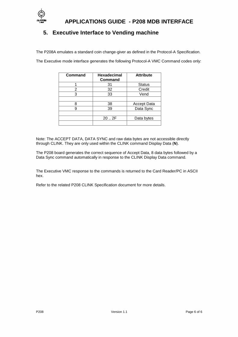
5. Executive Interface to Vending machine The P208A emulates a standard coin change-giver as defined in the Protocol-A Specification. The Executive mode interface generates the following Protocol-A VMC Command codes only:
Command Hexadecimal Command
Attribute
1 31 Status 2 32 Credit 3 33 Vend
8 38 Accept Data 9 39 Data Sync 20 .. 2F Data bytes
Note: The ACCEPT DATA, DATA SYNC and raw data bytes are not accessible directly through CLINK. They are only used within the CLINK command Display Data (N). The P208 board generates the correct sequence of Accept Data, 8 data bytes followed by a Data Sync command automatically in response to the CLINK Display Data command. The Executive VMC response to the commands is returned to the Card Reader/PC in ASCII hex. Refer to the related P208 CLINK Specification document for more details.
APPLICATIONS GUIDE - P208 MDB INTERFACE
P208 Version 1.1 Page 7 of 7
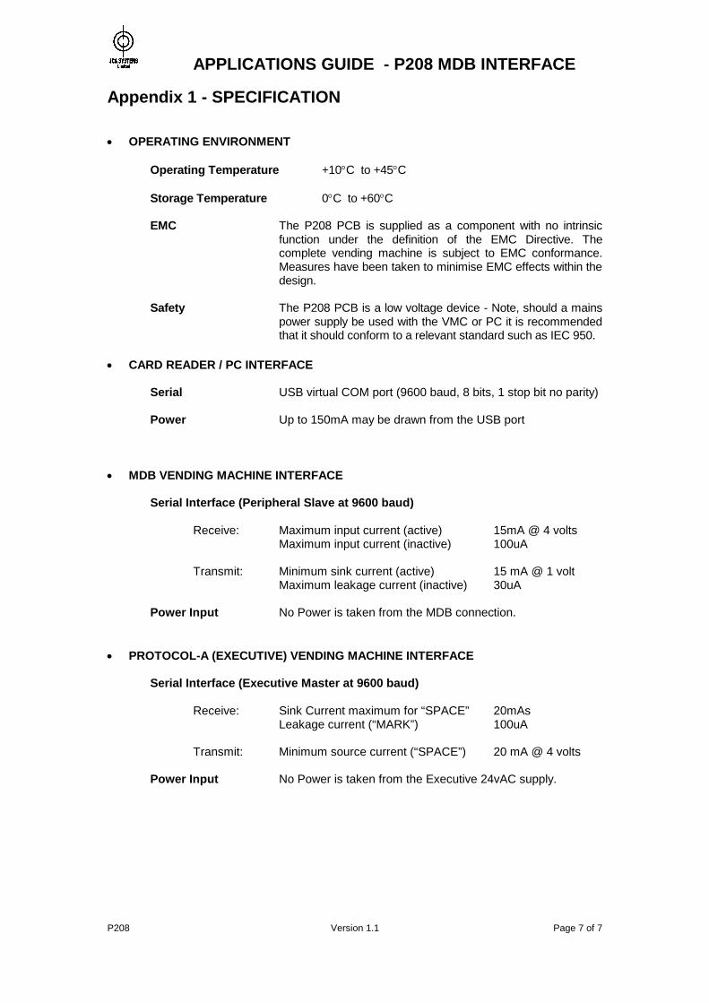
Appendix 1 - SPECIFICATION OPERATING ENVIRONMENT Operating Temperature +10C to +45C Storage Temperature 0C to +60C EMC The P208 PCB is supplied as a component with no intrinsic
function under the definition of the EMC Directive. The complete vending machine is subject to EMC conformance. Measures have been taken to minimise EMC effects within the design.
Safety The P208 PCB is a low voltage device - Note, should a mains
power supply be used with the VMC or PC it is recommended that it should conform to a relevant standard such as IEC 950.
CARD READER / PC INTERFACE Serial USB virtual COM port (9600 baud, 8 bits, 1 stop bit no parity) Power Up to 150mA may be drawn from the USB port MDB VENDING MACHINE INTERFACE Serial Interface (Peripheral Slave at 9600 baud) Receive: Maximum input current (active) 15mA @ 4 volts Maximum input current (inactive) 100uA Transmit: Minimum sink current (active) 15 mA @ 1 volt Maximum leakage current (inactive) 30uA Power Input No Power is taken from the MDB connection.
PROTOCOL-A (EXECUTIVE) VENDING MACHINE INTERFACE Serial Interface (Executive Master at 9600 baud) Receive: Sink Current maximum for “SPACE” 20mAs Leakage current (“MARK”) 100uA Transmit: Minimum source current (“SPACE”) 20 mA @ 4 volts Power Input No Power is taken from the Executive 24vAC supply.
APPLICATIONS GUIDE - P208 MDB INTERFACE
P208 Version 1.1 Page 8 of 8
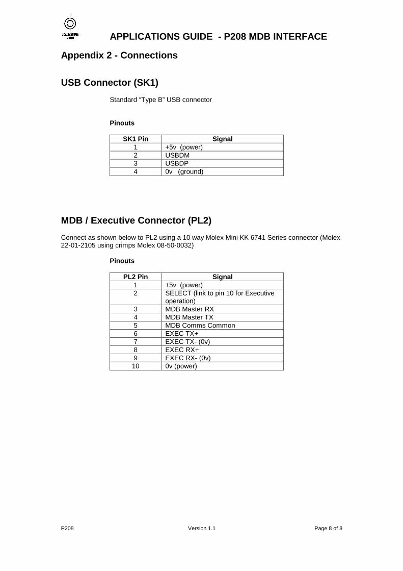
Appendix 2 - Connections USB Connector (SK1)
Standard “Type B” USB connector
Pinouts
SK1 Pin Signal 1 +5v (power) 2 USBDM 3 USBDP 4 0v (ground)
MDB / Executive Connector (PL2) Connect as shown below to PL2 using a 10 way Molex Mini KK 6741 Series connector (Molex 22-01-2105 using crimps Molex 08-50-0032)
Pinouts
PL2 Pin Signal 1 +5v (power) 2 SELECT (link to pin 10 for Executive
operation) 3 MDB Master RX 4 MDB Master TX 5 MDB Comms Common 6 EXEC TX+ 7 EXEC TX- (0v) 8 EXEC RX+ 9 EXEC RX- (0v)
10 0v (power)
APPLICATIONS GUIDE - P208 MDB INTERFACE
P208 Version 1.1 Page 9 of 9
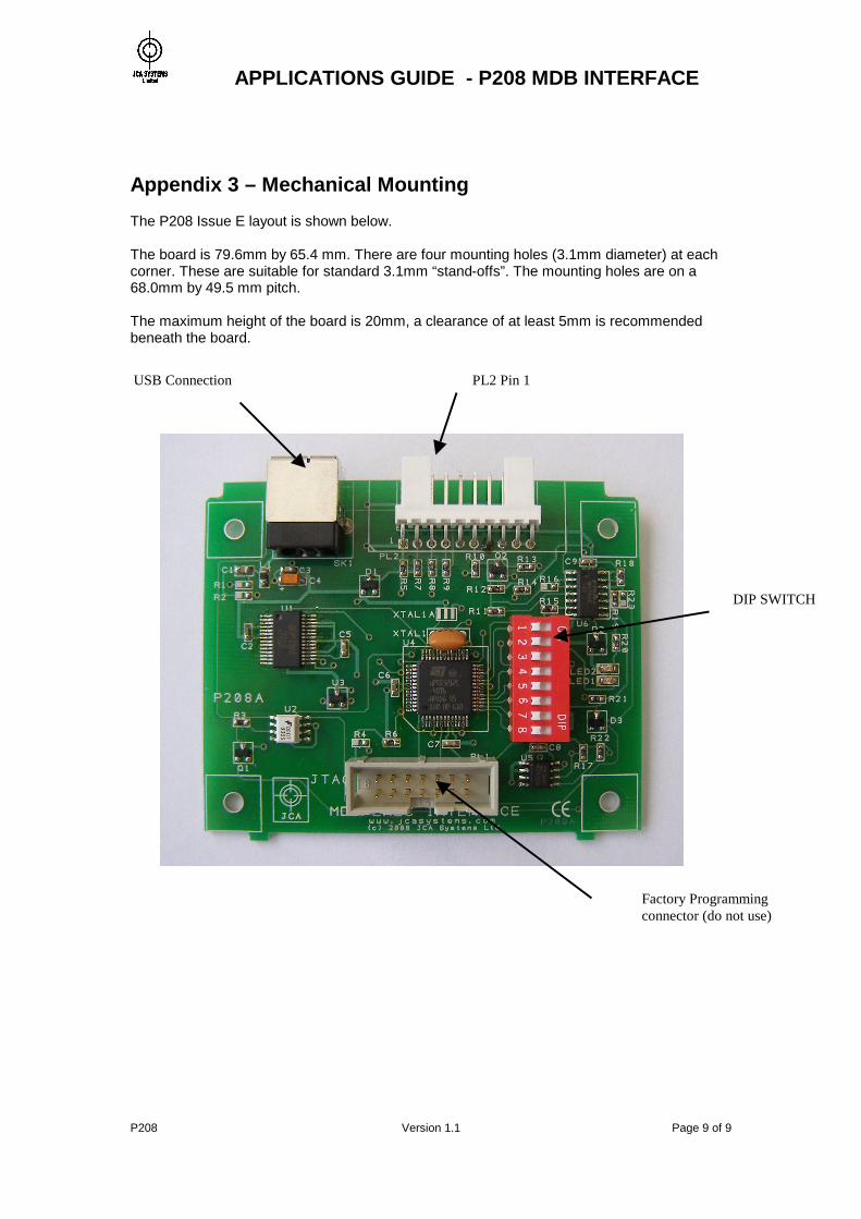
Appendix 3 – Mechanical Mounting The P208 Issue E layout is shown below. The board is 79.6mm by 65.4 mm. There are four mounting holes (3.1mm diameter) at each corner. These are suitable for standard 3.1mm “stand-offs”. The mounting holes are on a 68.0mm by 49.5 mm pitch. The maximum height of the board is 20mm, a clearance of at least 5mm is recommended beneath the board.
DIP SWITCH
PL2 Pin 1 USB Connection
Factory Programming connector (do not use)
APPLICATIONS GUIDE - P208 MDB INTERFACE
P208 Version 1.1 Page 10 of 10
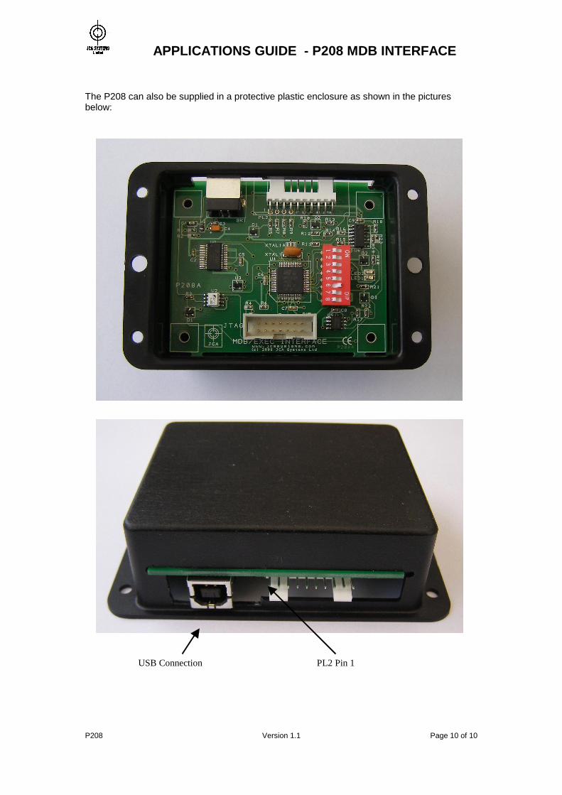
The P208 can also be supplied in a protective plastic enclosure as shown in the pictures below:
USB Connection PL2 Pin 1