Embed Size (px)
Citation preview
NCHU CSE LTE - 1
Architecture Overview
NCHU CSE LTE - 2
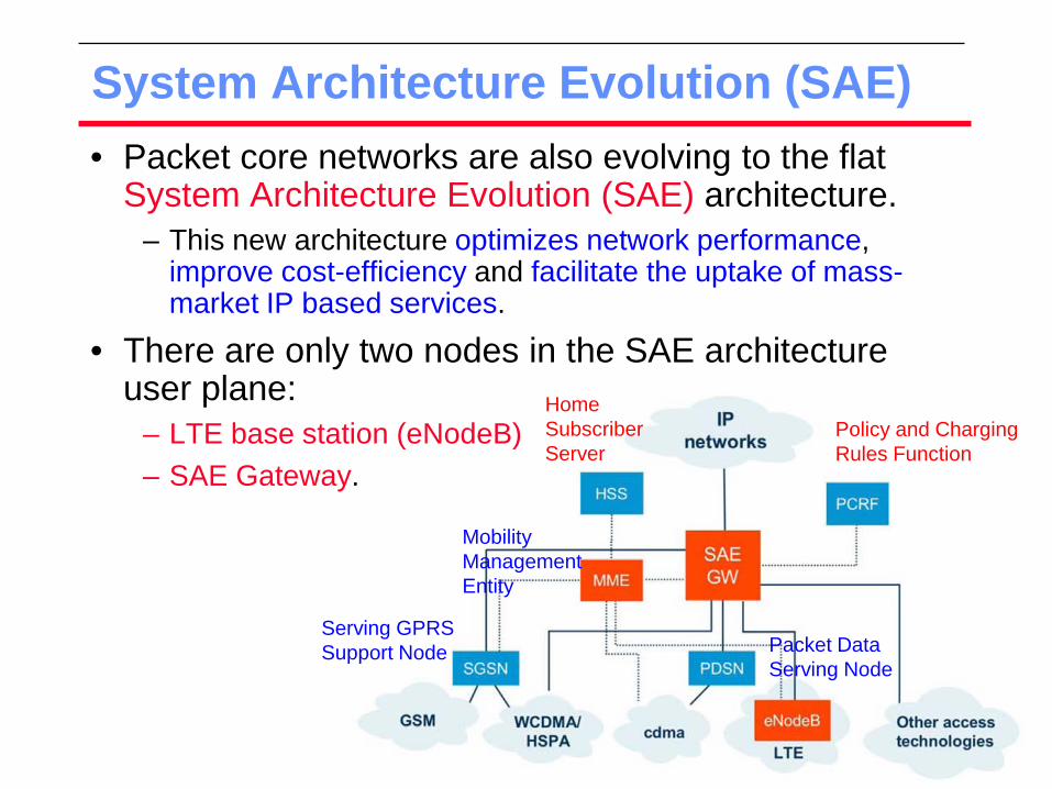
System Architecture Evolution (SAE) • Packet core networks are also evolving to the flat
System Architecture Evolution (SAE) architecture. – This new architecture optimizes network performance,
improve cost-efficiency and facilitate the uptake of mass-market IP based services.
• There are only two nodes in the SAE architecture user plane:
– LTE base station (eNodeB) – SAE Gateway.
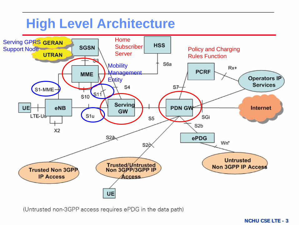
Policy and Charging Rules Function
Home Subscriber Server
Mobility Management Entity
Serving GPRS Support Node Packet Data
Serving Node
NCHU CSE LTE - 3
High Level Architecture Policy and Charging Rules Function
Home Subscriber Server
Mobility Management Entity
Serving GPRS Support Node
NCHU CSE LTE - 4
High Level Architecture • Functional Elements
– Evolved Radio Access Network (RAN) – Serving Gateway (SGW) – Mobility Management Entity (MME) – Packet Data Network Gateway (PDN GW)
• Key Features – EPC to EPS
» Evolved Packet Core -> Evolved Packet System » Separation of the network entity that performs control-plane
functionality (MME) from the network entity that performs bearer-plane functionality (SGW) with a well defined open interface between them (S11).
– S1-flex Mechanism » provides support for network redundancy and load sharing of
traffic across network elements in the CN (core network), the MME and the SGW,
NCHU CSE LTE - 5
Radio-Interface Architecture • In 3GPP
– the overall system architecture of both the Radio-Access Network (RAN) and the Core Network (CN) was revisited, including the split of functionality between the two network parts.
» The RAN is responsible scheduling, radio-resource handling, retransmission protocols, coding and various multi-antenna schemes.
• For LTE – it was known as the System Architecture Evolution (SAE)
and resulted in a flat RAN architecture, as well as a new core network architecture referred to as the Evolved Packet Core (EPC).
– The RAN and the EPC can be referred to as the Evolved Packet System (EPS).
NCHU CSE LTE - 6
Radio-Interface Architecture • The EPC is responsible for providing a complete
mobile-broadband network. – This includes authentication, charging functionality, and
setup of end-to-end connections.
• Handling these functions separately, instead of
integrating them into the RAN, is beneficial as it allows for several radio-access technologies to be served by the same core network.
NCHU CSE LTE - 7
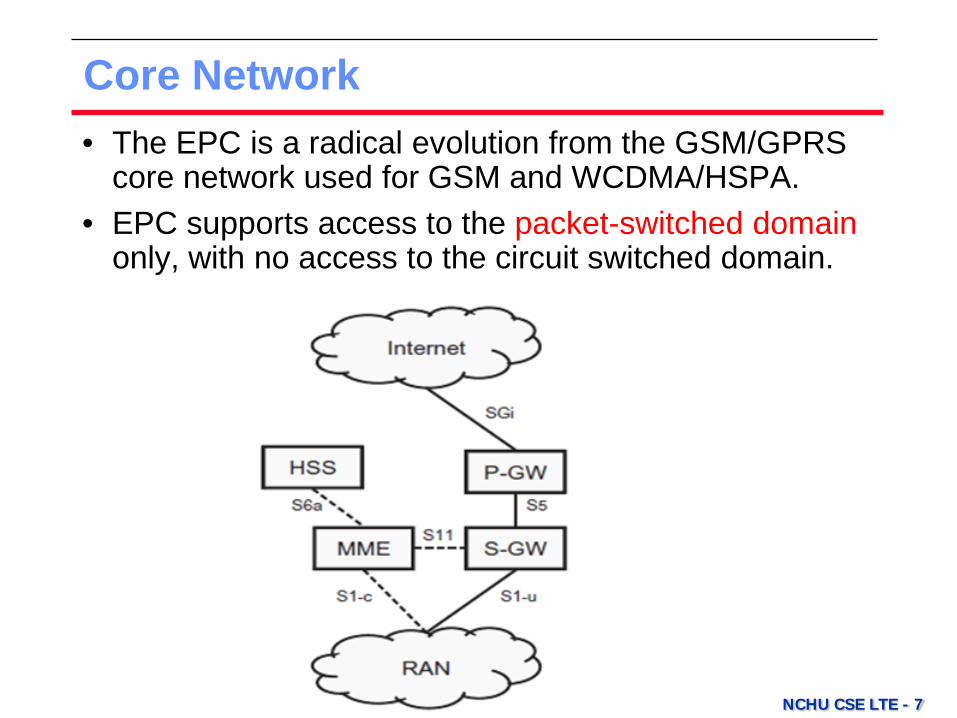
Core Network • The EPC is a radical evolution from the GSM/GPRS
core network used for GSM and WCDMA/HSPA. • EPC supports access to the packet-switched domain
only, with no access to the circuit switched domain.

NCHU CSE LTE - 8
Core Network • The Mobility Management Entity (MME) is the control-
plane node of the EPC. – include connection/release of bearers to a terminal, handling
of IDLE to ACTIVE transitions, and handling of security keys.
• The Serving Gateway (S-GW) is the user-plane node connecting the EPC to the LTE RAN.
– The S-GW acts as a mobility anchor when terminals move between eNodeBs, as well as a mobility anchor for other 3GPP technologies (GSM/GPRS and HSPA).
• The Packet Data Network Gateway (PDN Gateway, P-GW) connects the EPC to the internet.
– allocates the IP address for a specific terminal, as well as quality-of service enforcement according to the policy controlled by the Policy and Charging Rules Function (PCRF).

NCHU CSE LTE - 9
Core Network • The EPC also contains other types of nodes
– such as Policy and Charging Rules Function (PCRF) responsible for quality-of-service (QoS) handling and charging.
• Home Subscriber Service (HSS) node, a database containing subscriber information.
• In an actual physical implementation, several of them may very well be combined.
– For example, the MME, P-GW, and S-GW could very well be combined into a single physical node.

NCHU CSE LTE - 10
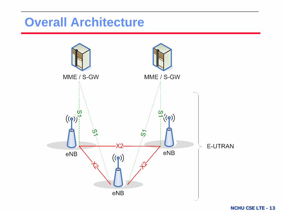
Radio-Access Network • LTE radio-access network uses a flat architecture
with a single type of node – eNodeB (eNB). – The eNodeB is responsible for all radio-related functions.
• eNB is connected to the EPC by means of the S1 interface
– to the S-GW by S1 user-plane part, S1-u. – to the MME by S1 control-plane part, S1-c.
NCHU CSE LTE - 11
Radio-Access Network • One eNB can be connected to multiple MMEs/S-GWs
for the purpose of load sharing and redundancy.
• The X2 interface, connecting eNodeBs to each other, is mainly used to support active-mode mobility.
– is used to support lossless mobility between neighboring cells by packet forwarding.
– is used for multi-cell Radio Resource Management (RRM) functions such as Inter-Cell Interference Coordination (ICIC).
NCHU CSE LTE - 12
Summary
• The E-UTRAN (Evolved Universal Terrestrial Radio Access) consists of eNodeBs, providing the
– user plane (PDCP/RLC/MAC/PHY) and – control plane (RRC) protocol terminations.
• The eNodeBs are interconnected with each other by means of the X2 interface.
• The eNodeBs are also connected – to the EPC (Evolved Packet Core) by the S1 interface, – to the MME (Mobility Management Entity) by the S1-MME – to the Serving Gateway (S-GW) by means of the S1-U.
• The S1 interface supports a many-to-many relation between MMEs/Serving Gateways and eNodeBs.
NCHU CSE LTE - 13
Overall Architecture

NCHU CSE LTE - 14
Functional Split between E-UTRAN and EPC
internet
eNB
RB Control
Connection Mobility Cont.
eNB MeasurementConfiguration & Provision
Dynamic Resource Allocation (Scheduler)
PDCP
PHY
MME
S-GW
S1MAC
Inter Cell RRM
Radio Admission Control
RLC
E-UTRAN EPC
RRC
Mobility Anchoring
EPS Bearer Control
Idle State Mobility Handling
NAS Security
P-GW
UE IP address allocation
Packet Filtering
User Plane
Control Plane
Non Access Stratum
NCHU CSE LTE - 15
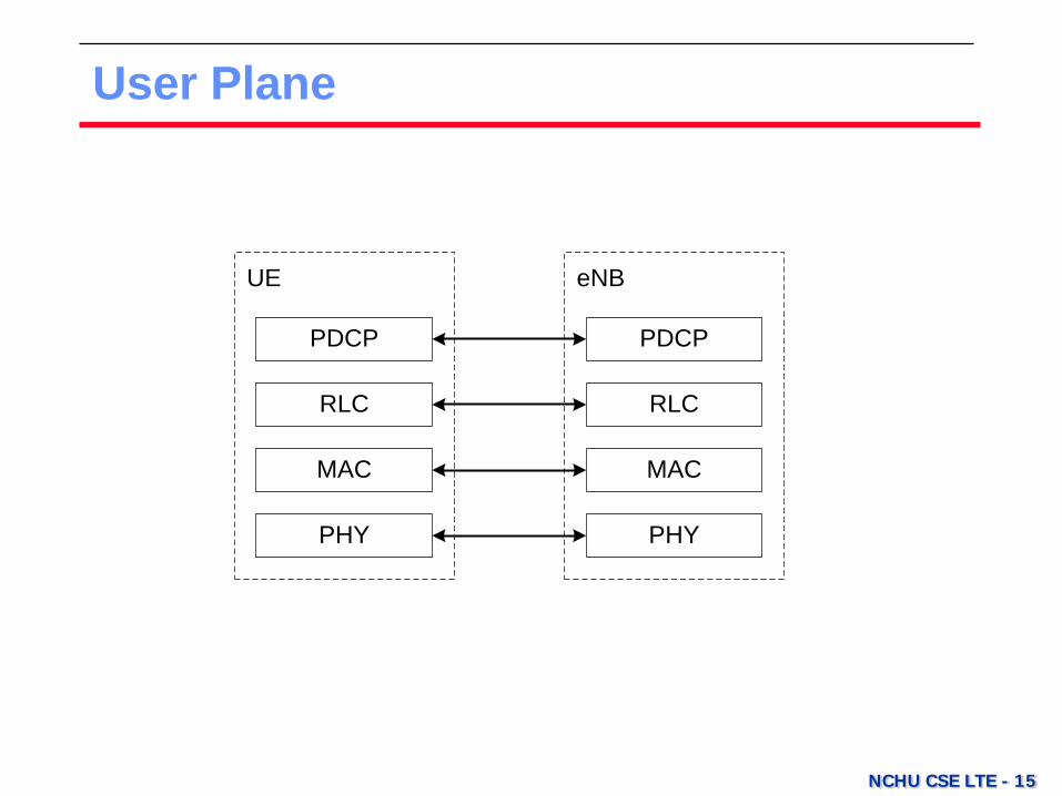
User Plane
eNB
PHY
UE
PHY
MAC
RLC
MAC
PDCPPDCP
RLC

NCHU CSE LTE - 16
Control Plane
eNB
PHY
UE
PHY
MAC
RLC
MAC
MME
RLC
NAS NAS
RRC RRC
PDCP PDCP

NCHU CSE LTE - 22
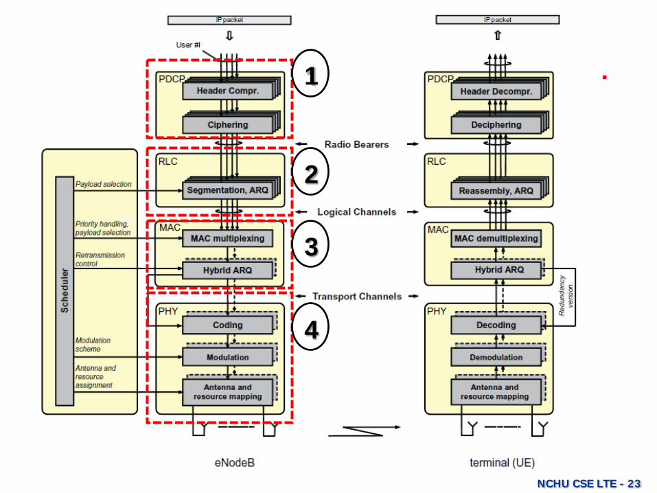
Radio Protocol Architecture • RAN protocol architecture is designed for the user as
well as the control planes.
NCHU CSE LTE - 23
1
2
3
4
NCHU CSE LTE - 24
Radio Protocol Architecture 1. Packet Data Convergence Protocol (PDCP)
performs IP header compression. – The header-compression mechanism is based on Robust
Header Compression (ROHC). – Also responsible for ciphering and, for the control plane,
integrity protection of the transmitted data, as well as in-sequence delivery and duplicate removal for handover.
2. Radio-Link Control (RLC) is responsible for segmentation/concatenation, retransmission handling, duplicate detection, and in-sequence delivery to higher layers. – provides services to the PDCP in the form of radio bearers.
NCHU CSE LTE - 25
Radio Protocol Architecture 3. Medium-Access Control (MAC) handles multiplexing
of logical channels, hybrid-ARQ retransmissions, and uplink and downlink scheduling. – The scheduling functionality is located in the eNodeB for
both uplink and downlink. – provides services to the RLC in the form of logical channels.
4. Physical Layer (PHY) handles coding/decoding, modulation/demodulation, multi-antenna mapping, and other typical physical-layer functions. – offers services to the MAC layer in the form of transport
channels.

NCHU CSE LTE - 26
LTE Data Flow 1. The PDCP performs (optional) IP-header
compression, followed by ciphering. – A PDCP header is added, carrying information required for
deciphering in the terminal.
2. The RLC protocol performs concatenation and/or segmentation of the PDCP SDUs and adds an RLC header. – The RLC PDUs are forwarded to the MAC layer, which
multiplexes a number of RLC PDUs and attaches a MAC header to form a transport block.
3. The physical layer attaches a CRC to the transport block, performs coding and modulation, and transmits the resulting signal, possibly using multiple transmit antennas.

NCHU CSE LTE - 27
LTE Data Flow
NCHU CSE LTE - 28
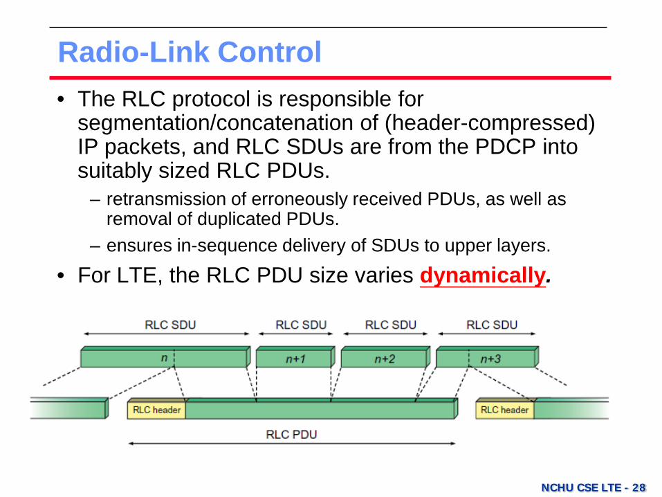
Radio-Link Control • The RLC protocol is responsible for
segmentation/concatenation of (header-compressed) IP packets, and RLC SDUs are from the PDCP into suitably sized RLC PDUs.
– retransmission of erroneously received PDUs, as well as removal of duplicated PDUs.
– ensures in-sequence delivery of SDUs to upper layers.
• For LTE, the RLC PDU size varies dynamically.
NCHU CSE LTE - 29
Radio-Link Control • Since the RLC, scheduler, and rate adaptation
mechanisms are all located in the eNodeB, dynamic PDU sizes are easily supported for LTE.
• By monitoring the sequence numbers of the incoming PDUs, the receiving RLC can identify missing PDUs.
• Status reports are then fed back to the transmitting RLC entity, requesting retransmission of missing PDUs.
– MAC-based hybrid-ARQ protocol.
NCHU CSE LTE - 30
Medium-Access Control • The MAC layer handles logical-channel multiplexing,
hybrid-ARQ retransmissions, and uplink and downlink scheduling.
– Is also responsible for multiplexing/demultiplexing data across multiple component carriers when carrier aggregation is used.
• The MAC provides services to the RLC in the form of logical channels.
• A logical channel is defined by the type of information it carries and is generally classified
– as a control channel, used for transmission of control and configuration information necessary for operating.
– as a traffic channel, used for the user data.
NCHU CSE LTE - 31
Logical Channels • The Broadcast Control Channel (BCCH), used for
transmission of system information from the network to all terminals in a cell.
– A terminal needs to acquire the system information to find out how the system is configured.
• The Paging Control Channel (PCCH), used for paging of terminals whose location on a cell level is not known to the network.
• The Common Control Channel (CCCH), used for transmission of control information in conjunction with random access.
• The Dedicated Control Channel (DCCH), used for transmission of control information to/from a terminal.
NCHU CSE LTE - 32
Logical Channels • The Multicast Control Channel (MCCH), used for
transmission of control information required for reception of the MTCH (see below).
• The Dedicated Traffic Channel (DTCH), used for transmission of user data to/from a terminal.
– This is the logical channel type used for transmission of all uplink and non-MBSFN (Multicast-Broadcast Single Frequency Network) downlink user data.
• The Multicast Traffic Channel (MTCH), used for downlink transmission of MBMS services.
NCHU CSE LTE - 33
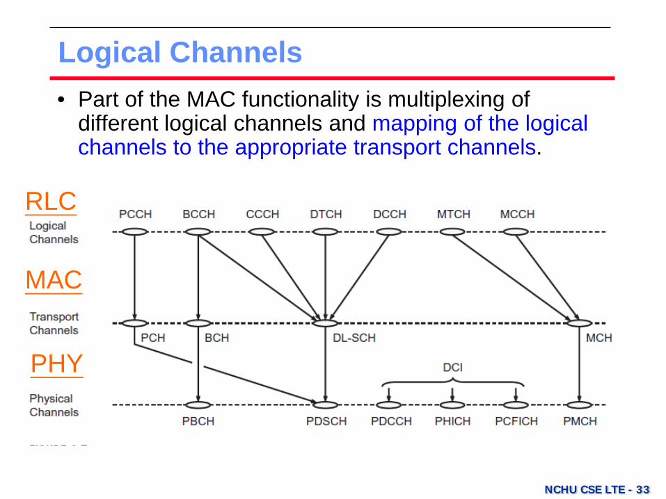
Logical Channels • Part of the MAC functionality is multiplexing of
different logical channels and mapping of the logical channels to the appropriate transport channels.
RLC
MAC
PHY