Embed Size (px)
Citation preview

R.O. Ritchie, 2004
ASM Intl. Materials and Processes for Medical Devices Conference St. Paul, Minnesota, August 25-27, 2004
Role of Fracture Mechanics in Life Prediction Role of Fracture Mechanics in Life Prediction and Quality Control of Medical Implantsand Quality Control of Medical Implants
Robert O. RitchieRobert O. Ritchie
Materials Sciences Division, Lawrence Berkeley National Laboratoryand
Department of Materials Science and EngineeringUniversity of California at Berkeley
email: [email protected]
Work supported by ATS Medical, Baxter Healthcare, CV Medical, Inc., Shiley, Sorin, and St. Jude Medical

R.O. Ritchie, 2004
Substitutive MedicineSubstitutive Medicine
• The fundamental tenet of substitutive medicine is that beyond a certain stage of failure, it is more effective to remove and replace a malfunctioning organ than to seek in vain to cure it
• Functional disabilities due to destruction or wear of body partscan be addressed in two ways:
- implantation of prosthetic devices
- transplantation of natural organs

R.O. Ritchie, 2004
6,013243549760822023
1,7992,837
No. who died (1 yr)
78,63676,963TOTALS187170Intestine198209Heart + Lung
3,7563,708Lung3,8033,934Heart2,4252,378Kidney-Pancreas408387Pancreas
16,97418,047Liver50,88547,830Kidney
20022001ORGANS
Waiting List for OrgansWaiting List for Organs
www.ustransplant.org

R.O. Ritchie, 2004

R.O. Ritchie, 2004
The Problem!The Problem!
NIH Statistics
• 20 million people in U.S. have at least one medical implant
• $100 billion spent annually on prostheses and artificial organs
• 20% of all surgeries are to replace failed devices
Three Immediate Problems
• New implant materials – e.g., bone-like materials to prevent stress shielding, heart valve materials to prevent thrombosis
• Improved implant/tissue interfaces – as vast majority of devices fail due to interface failure
• Lifetime prediction for medical devices

R.O. Ritchie, 2004
polyurethane430,000Pacemakercellulose16,000,000Renal dialyzer
titanium300,000Dental implantsilicone192,000Breast implantstainless steel, NiTi, Co-Cr>1,000,000Stent (cardiovascular)pig valve, PyC, Ti, Co-Cr200,000Heart valvesilicone, teflon200,000,000Cathetertitanium, Co-Cr, PE500,000Hip & knee prosthesisPTFE, PET250,000Vascular graftsilicone acrylate30,000,000Contact lensPMMA2,700,000Intraocular lensBiomaterialNumber/yearDevice
Medical Implants Used in the U.S.Medical Implants Used in the U.S.

R.O. Ritchie, 2004
GoldPolymersTantalumCarbonNiobiumTricalciumphosphateZirconiumBioglassesTitanium, NitinolAluminaStainless steelHydroxyapatiteCo-Cr alloys
BiomaterialsBiomaterials
Less than 20 chemical compounds among 1.5 million candidateshave been successfully incorporated into clinical devices

R.O. Ritchie, 2004
Metallic ImplantsMetallic Implants
Major problems associated with metallic implantsIncompatible tissue/implant properties
Implants loosen with timeRequire revision surgery
Knee prosthesis
Dental implant
Hip stem

R.O. Ritchie, 2004
Total Hip Replacement Total Hip Replacement –– OsteolysisOsteolysis
• We take about one million steps a year
• As years pass, strong shock waves caused by walking, running & climbing erode cushioning between ball & socket at top of leg
• Soon, bone grinding on bone causes osteoarthritis, a condition that brings crippling pain and slows everything we do
• What's the answer? For more than 250,000 Americans a year: hip replacement surgery

R.O. Ritchie, 2004
Heart Valve Prostheses and Heart Valve Prostheses and StentsStents
• 1 million cardiovascular stents and over 200,000 heart valves are implanted in the U.S. each year
• mechanical failure is rare, but with valves has accounted for hundreds of patient deaths in past 20 yrs
• as the human heart beats some 40 million times/yr, fatigue is the prime mechanism of mechanical failure
• design & reliability of mechanical valves and stents must be focused on devices that last in excess of patient lifetimes, ~108 - 109 cycles
• quality control is thus essential to maintain device components that meet this criteria
Superiorvena cava
Inferiorvena cava
AortaPulmonary
arteries
PulmonaryveinsR.
AtriumL.
Atrium
TAo
M
R. Vent L.
Vent

R.O. Ritchie, 2004
StentingStenting of Arteriesof Arteries
occlusion
stent
• Stents manufactured with:- AISI 316 stainless steel- Nitinol (Ni-Ti alloy) - Co-Cr (Haynes 25) alloy
uninflated NiTi stent
1 mm
made by NDC, a J&J Company, Fremont, CA
self-inflating endovascular stent
• $3.48 billion market this year• projected to rise to $7.1 billion by 2006
R.O. Ritchie, 2004
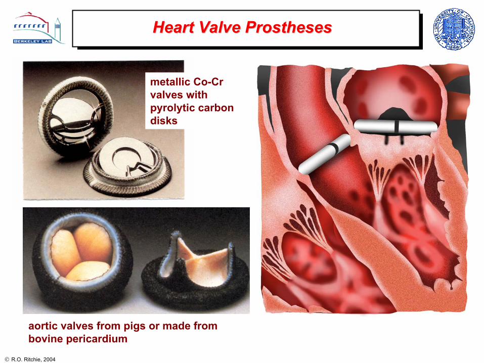
Heart Valve ProsthesesHeart Valve Prostheses
aortic valves from pigs or made from bovine pericardium
metallic Co-Cr valves with pyrolytic carbon disks

R.O. Ritchie, 2004
Mechanical Heart Valve ProsthesesMechanical Heart Valve Prostheses
• In the aftermath of the Shiley valve problems, the trend has been away from metallic valves towards pyrolytic carbon valves
• with respect to fracture toughness, pyrolyticcarbon is more than an order of magnitude more brittle than Ti or Co-Cr alloys
• hence special care must be taken in design and life-prediction procedures to prevent in vivo fractures
~235 - 50200 - 120055 - 90Nitinol (Ni-Ti) alloy
(MPa√m)(MPa√m)(MPa)(GPa)
~6 - 8
~3 - 4
4.5 - 10
~0.7 - 2
Fatigue threshold
250 - 560
925 - 1000
450 - 1000
350 - 530
Strength
>100210 Stainless steel (316L)
60 - 80115 Ti-6Al-4V alloy
~60209Co-Cr (Haynes 25) alloy
1 - 227 - 31Pyrolytic carbon
Fracture toughness
Young’s modulus
Prosthetic material

R.O. Ritchie, 2004
Comparison of Metallic Implant MaterialsComparison of Metallic Implant Materials
• for devices such as stents and heart valves, fatigue can be the limiting damage mechanism
• of the typical materials used (316 SS, Co-Cr, Ti, Ti-6Al-4V and NiTi), Nitinol has the worst fatigue-crack growth properties
• interestingly, Nitinol is invariably used in the superelastic austenitic condition, which is the worst microstructure for fatigue resistance
∆K = Q ∆σ (πa)½
McKelvey & Ritchie, J. Biomed. Mat. Res.,1999; Metall. Trans., A,2001

R.O. Ritchie, 2004
….. and pyrolytic carbon is even worse!!!
Ritchie, Mater. Sci. Eng.,1989
R.O. Ritchie, 2004
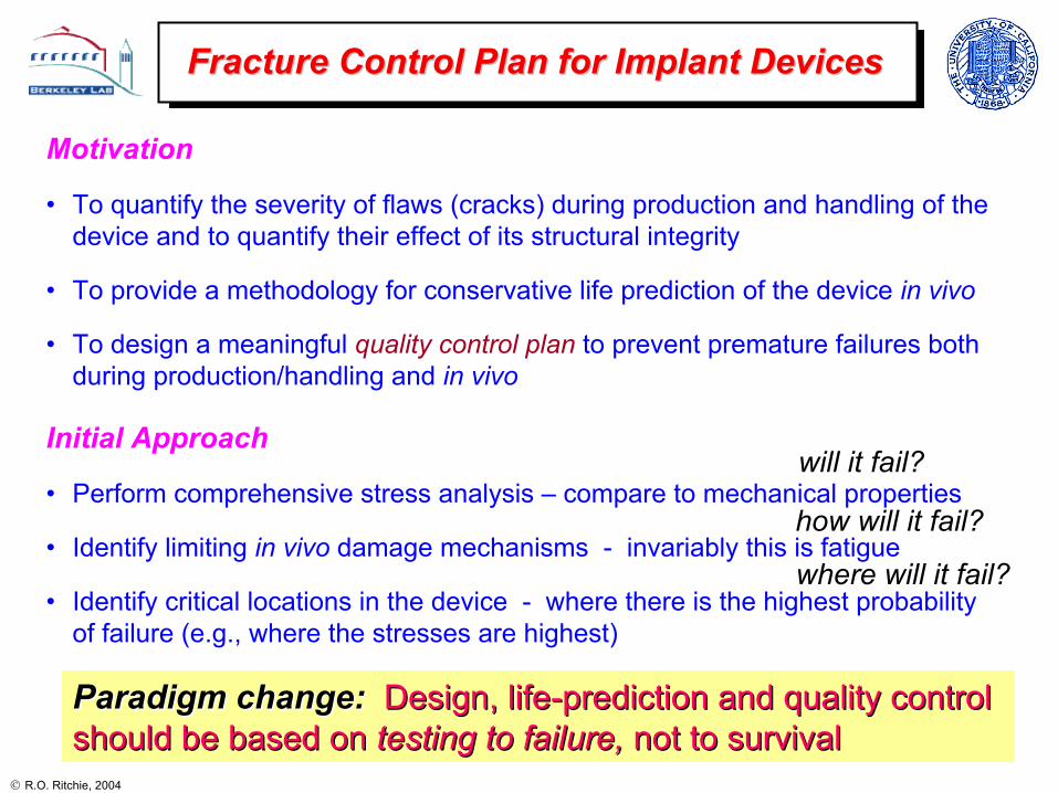
Fracture Control Plan for Implant DevicesFracture Control Plan for Implant Devices
Motivation
• To quantify the severity of flaws (cracks) during production and handling of the device and to quantify their effect of its structural integrity
• To provide a methodology for conservative life prediction of the device in vivo
• To design a meaningful quality control plan to prevent premature failures both during production/handling and in vivo
Initial Approach
• Perform comprehensive stress analysis – compare to mechanical properties
• Identify limiting in vivo damage mechanisms - invariably this is fatigue
• Identify critical locations in the device - where there is the highest probability of failure (e.g., where the stresses are highest)
will it fail?
how will it fail?
where will it fail?
Paradigm change:Paradigm change: Design, lifeDesign, life--prediction and quality control prediction and quality control should be based onshould be based on testing to failure, testing to failure, not to survivalnot to survival

R.O. Ritchie, 2004
Methodologies for Fatigue Life PredictionMethodologies for Fatigue Life Prediction
Stress-Strain/Life (S/N) Approach• Traditional approach relating applied
stresses/strains to the total fatigue life, i.e., cycles both to initiate and propagate a crack to failure
• Pros: simple testing and analysis• Cons: not always conservative,
cannot account for flaws, need many tests to give good statistics
100 1000 10000 100000 1000000 10000000100000000NO. OF CYCLES (log)
0
10
20
30
40
50
60
70
STR
ESS
AMPL
ITU
DE
(MPa
)
2 Hz20 Hz
HUMAN DENTINR = 0.1 25oC, HANK'S BSS
σa
σma
x
σmin
σm
102 103 104 105 106 107 108
, Nf, σ
a (M
Pa)
Damage-Tolerant Approach• Fracture mechanics approach where life is
computed as the cycles for a pre-existing crack to propagate to failure
• Pros: generally conservative, can relate device lifetimes to device quality
• Cons: more difficult testing, problems with small cracks0.1 1 100.2 0.3 0.4 0.5 0.60.70.80.9 2 3 4 5 6 7 8 9
STRESS-INTENSITY RANGE, ∆K (MPa√m)
1E-010
1E-009
1E-008
1E-007
1E-006
1E-005
1E-004
1E-003
CR
AC
K-G
RO
WTH
RA
TE, d
a/dN
(m/c
ycle
)
HUMAN CORTICAL BONE37OC, HBSSR=0.1, 1Hz
10-3
10-4
10-5
10-6
10-7
10-8
10-9
10-
10
∆K = Q ∆σ (πa)½

R.O. Ritchie, 2004
• critical locations identified at the base of the struts, as these experience the highest (bending) stresses
• outlet strut is particularly critical as it is plastically deformed during occluderinsertion
Case Study: metallic mechanical heart valveCase Study: metallic mechanical heart valve
Shiley Monostrut valve• Co-Cr (Haynes 25) housing
• pyrolytic carbon occluder
• no welds!

R.O. Ritchie, 2004
• identify limiting failure mechanism(s)
• define critical location(s)
• estimate worse-case in vivo loading (e.g., from pulse duplicator studies)
• compute worse-case in vivo stresses (e.g., from numerical analysis)
• measure residual stresses in device material (e.g., by x-ray diffraction)
• determine stress-life (S-N) data under simulated physiological conditions
• estimate safe life as a function of worse-case stresses
StressStress--Strain/Life (SStrain/Life (S--N) AnalysisN) Analysis
• stress-life data represents the total lifetime as a function of stress amplitude
• depending upon the loading, data must be measured, or converted, to reflect role of mean stress (σm):
−
∆=
∆ −=
UTS
mRR
σσσσ 1
221
(R = σmin/σmax) Ritchie & Lubock, J. Biomech. Mech., 1986
fatigue limit

R.O. Ritchie, 2004
• identify limiting failure mechanism(s)
• define critical location(s)
• estimate worse-case in vivo loading
• compute worse-case in vivo stresses
• measure residual stresses
• compute of stress-intensity factors K for worse-case flaws in critical locations
• measure crack velocity-stress intensity (v-K) relationships in vitro
• determine critical (largest) defect size to cause final failure (e.g., defined by the fracture toughness, KIc)
• compute lifetimes as a function of initial flaw size
• calculate initial flaw size that can yield an acceptable life – the required detectable flaw size
• design of a non-destructive testing procedure to detect such flaws in every device - this provides the basis for Quality Control of the device
Procedures for DamageProcedures for Damage--Tolerant AnalysisTolerant Analysis
K = Q σ (πa)½
where K is the stress intensityσ is the total in-service stressa is the crack sizeQ is a geometry factor (of order unity)
da/dN = C(∆K)m

R.O. Ritchie, 2004
Load-line Displacement
⇓Data
Recorder⇓
Computer Controlling
System
LVDT
Normalized Crack Length
(a/W)
calibrationcurve
Load
-line
D
ispl
acem
ent
Time (t)
calculatedcrack length
Cra
ck L
engt
h (a
)
Stress-intensity Range (∆K)
fatigue-crack growth data
Cra
ck G
row
th R
ate
(da/
dN)
Measurement of FatigueMeasurement of Fatigue--Crack Growth PropertiesCrack Growth Properties
• crack-growth rates, with respect to time (da/dt) or cycles (da/dN), measured in simulated physiological environment
• results in Ringer’s solution for Co-Cr alloy Haynes 25 show that fatigue cracks will propagate (for R ~ 0) above a fatigue threshold of ∆KTH ~ 5 MPa√m
da/dN = C(∆K)m

R.O. Ritchie, 2004
Computation of StressComputation of Stress--Intensity FactorsIntensity Factors
• compute of stress-intensity factors, K, for worse-case flaws in critical locations
• compare K values, as a function of crack size, a, with critical values for failure:
KIc - fracture toughness
∆KTH - threshold for fatigue cracking
KIscc - threshold for sustained-load cracking
• This provides an initial quantification as a function of flaw size to whether the device will either:
- experience device failure
- suffer subcritical crack growth by sustained-load cracking or more likely fatigue
Ritchie & Lubock, J. Biomech. Mech., 1986
∆KTH
∆KTH

R.O. Ritchie, 2004
Estimation of Fatigue LifetimesEstimation of Fatigue Lifetimes
Inputs
• identify K solution for worst-case crack configuration, e.g., for a circular flaw:
K = Q σ (π a)½ , where Q = 2/π
• determine crack-growth relationship:
da/dN = C (∆K)m
Damage-tolerant calculation• integrate between the limits of the initial, ao,
and final, af, crack sizes to give the number of cycles to failure, Nf:
da/dN = C [Q ∆σ (πa)½]m
220mmmm
a
a
N
faQC
dadNNf
o
f
πσ∆== ∫∫
( ) ( ) ( )
−
∆−= −−
22
22
2
11
2
2m
f
m
o
mmm aaQCm πσwhere af = ac = (1/π) (Kmax/Q σmax)2
i.e., whenKmax = KIc
Ritchie & Lubock, J. Biomech. Mech., 1986
R.O. Ritchie, 2004
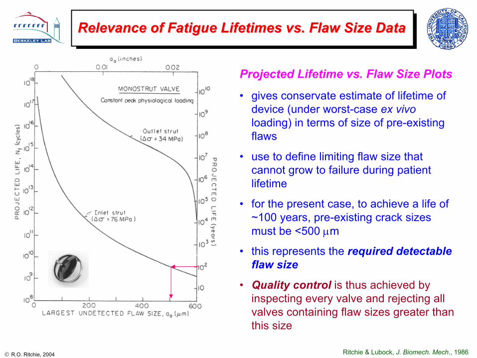
Relevance of Fatigue Lifetimes vs. Flaw Size DataRelevance of Fatigue Lifetimes vs. Flaw Size Data
Projected Lifetime vs. Flaw Size Plots
• gives conservate estimate of lifetime of device (under worst-case ex vivoloading) in terms of size of pre-existing flaws
• use to define limiting flaw size that cannot grow to failure during patient lifetime
• for the present case, to achieve a life of ~100 years, pre-existing crack sizes must be <500 µm
• this represents the required detectable flaw size
• Quality control is thus achieved by inspecting every valve and rejecting all valves containing flaw sizes greater than this size
Ritchie & Lubock, J. Biomech. Mech., 1986

R.O. Ritchie, 2004
Problem of Small CracksProblem of Small Cracks
• when cracks are physically very small, fatigue threshold ∆KTH is no longer constant and decreases with decreasing crack size
• this is the “small-crack effect” and can lead to non-conservative life predictions
• in engineering terms, this effect occurs at crack sizes defined by:
lo ≈ (1/π) (∆KTH/Q∆σe)2
∆KTH = large-crack fatigue threshold∆σe = smooth-bar fatigue limitand K = Qσ(πa)½
Ritchie & Lubock, J. Biomech. Eng., 1986
• in the example of the Monostrut valve, the small crack effect in Co-Cr alloy only occurred for crack sizes less than ~75 µm and thus was not relevant
Kitagawa-Takahashi diagram
unsafe
safe
unsafe
safe
unsafe
safe

R.O. Ritchie, 2004
Fracture Control Analysis for Fracture Control Analysis for StentsStents
flaws were numerically introduced in the expanded stent in critical locations
flaw profile assumed to be semi-elliptical with a depth-to-length (c/2a) ratio of 1/3 (a = half surface length; c = depth), as verified by FIB microscopy of actual flaws
for stress-life predictions, an infinite-life endurance limit and UTS (both determined at 95% confidence/99% reliability) used to calculate an “adjusted” endurance limit based on predicted maximum mean stresses
corresponding damage-tolerant analysis assumes a threshold of ∆KTH = 2.58 MPa√m (R = 0.75) (Ritchie & Lubock, J. Biomech. Eng., 1986)
Ramesh, Bergermeister, Grishaber, Ritchie, 2004
Cordisendovascular stent
500 nm
2 µm

R.O. Ritchie, 2004
1.E+00
1.E+02
1.E+04
1.E+06
1.E+08
1.E+10
1.E+12
1.E+14
1.E+16
1.E+18
1.E+20
1.E+22
0 20 40 60 80 100
initial flaw size (microns)
proj
ecte
d lif
e (c
ycle
s)
0.0
0.5
1.0
1.5
2.0
2.5
1 10 100 1000 10000total flaw length in microns
Stre
ss in
tens
ity fa
ctor
in k
si*s
qrt(i
n)
Delta K Threshold
Delta K for flaw on stent wall (FEA)
Delta K for through-edge-flaw at side-wall (FEA)
flaw offset towards OD on stent wall (no edge-rounding assumed in model)
flaw centered on stent wall
"short flaw" range "long flaw" range
through-edge flaw
Fracture Mechanics Analysis of Fracture Mechanics Analysis of StentStent
Ramesh, Bergermeister, Grishaber, Ritchie, 2004
• stress intensities for worst-case cracks in stent computed from numerical analysis
• thresholds as a function of flaw size estimated using Kitagawa diagrams from experimental S/N and ∆KTH data
• lifetimes determined by integration of crack-growth laws
• predicted life is a function of pre-existing flaw size – basis for quality controlbasis for quality control
unsafe
safe
30 yrs

R.O. Ritchie, 2004
• compared to metallic Co-Cr and Ti alloys, pyrolytic carbon is more than an order of magnitude more brittle
• as brittle materials are extremely sensitive to stress and presence of flaws, life prediction can be quite difficult - i.e., extremely sensitive to stress and flaw size, as:
Nf ∝ σ-m & a-(m-2)/2
• residual stresses in pyrolytic carbon and pyrolytic-carbon coated graphite can be large (~30-100 MPa) and are difficult to measure
• required detectable flaw sizes can be extremely small (~tens of microns)
What about What about pyrolyticpyrolytic carbon heart valves? carbon heart valves?
~2 - 4
~50 - 100
(slope of da/dN-∆K curve)
Paris exponent
m(µm)(MPa√m)(MPa√m)
4.5
~0.7 - 2
Fatigue threshold,
∆KTH
~0.5 to 1 mm60Co-Cr (Haynes 25) alloy
tens of microns1 - 2Pyrolytic carbon
Required detectable flaw size
Fracture toughness,
KIc
Material

R.O. Ritchie, 2004
Measurement of FatigueMeasurement of Fatigue--Crack Growth PropertiesCrack Growth Propertiesin in PyrolyticPyrolytic Carbon MaterialsCarbon Materials
• resulting crack-growth rate data, in the form of da/dN vs. ∆K plots, can show:
- significant scatter
- low thresholds (∆KTH ~ 0.7 to 2 MPa√m)
- very high Paris exponents of m ~ 50 - 100
Ritchie et al., J. Biomed. Mat. Res., 1990
• as pyrolyric carbon is so brittle, initiating cracks and controlling crack growth can be quite difficult

R.O. Ritchie, 2004
CavitationCavitation--Induced Fatigue Cracks in Induced Fatigue Cracks in PyrolyticPyrolytic CarbonCarbon

R.O. Ritchie, 2004
FractographyFractography of of PyrolyticPyrolytic CarbonCarbon
• in metallic materials, fatigue cracks have a unique morphology (e.g., fatigue striations)
• in pyrolytic carbon and graphite (like other brittle solids), the morphology of fatigue failures is essentially identical to overload failures
Ritchie, Dauskardt & Pennisi, J. Biomed. Mater. Res., 1992

R.O. Ritchie, 2004
Case Study: Case Study: PyrolyticPyrolytic Carbon Mechanical Heart ValveCarbon Mechanical Heart Valve
• da/dN data in pyrolyticcarbon is primarily a function of Kmax,
• da/dN = C′ (Kmax)m
• with Kmax,TH ~ 1 MPa√m
• m ~ 50 - 100
• damage-tolerant lifetime analyses can be performed for brittle implants in similar manner to metallic devices
• analyses are complicated by scatter in toughness and fatigue data and by the large crack-growth exponents
220mmmm
a
a
N
faQC
dadNNf
o
f
πσ∆== ∫∫ ( ) ( ) ( )
−
∆−= −−
22
22
2
11
2
2m
f
m
o
mmm aaQCm πσ
Ritchie, J. Heart Valve Disease, 1996

R.O. Ritchie, 2004
Relevance of Fatigue Lifetimes vs. Flaw Size DataRelevance of Fatigue Lifetimes vs. Flaw Size Data
• large crack-growth exponents of m ~ 50 – 100 in brittle materials leads to an extreme sensitivity of the life to stress and flaw size:
Nf ∝ σ -(50-100) & ao-(25-50)
• for device lifetime of ~100 yrs, initial flaw sizes must, in this case, be less than ~40 µm
• for quality control, this requires NDT procedures that can detect and reject all components that contain pre-existing flaws larger than this micron-scale size
Ritchie, J. Heart Valve Disease, 1996
220mmmm
a
a
N
faQC
dadNNf
o
f
πσ∆== ∫∫ ( ) ( ) ( )
−
∆−= −−
22
22
2
11
2
2m
f
m
o
mmm aaQCm πσ

R.O. Ritchie, 2004
• based on typical damage-tolerant life-prediction calculations, the required detectable defect sizes are:
- many hundred microns in metallic valves- tens of microns in pyrocarbon valves
• to detect such defect sizes in metallic valves, SEM can be used
• to detect the smaller defects in pyrocarbon valves, a proof test must be used- e.g., pneumatic pressure on the leaflets of the valve at a proof stress σp ~ 5
times physiological pressure- if the valve does not fail, then the maximum initial defect size ao must the
less than the critical defect size, ac, at that proof stress:
ao < 1/π (KIc/Q σp)2
- survival of the valve at a given σp implies a maximum ao, which in turn implies a minimum lifetime, Nf
- proof test must (i) simulate in vivo loading, (ii) not damage component, and(iii) must use upper-bound KIc (c.f., life prediction uses lower-bound)
Quality Control: Defect Detection (NDT)Quality Control: Defect Detection (NDT)

R.O. Ritchie, 2004
• in pyrolytic carbon, CVD processing can leave residual stresses far larger than in vivo stresses
• measurement complicated by the semi-crystalline structure and scatter in near-surface stresses
• accurate measurements can be obtained using a crack compliance technique
• an EDM crack is progressively cut into the component section and the resulting strain due to cutting recorded
• using linear superposition, the gradient in residual strain and stress can be accurately determined distance from mid-plane (mil)
stre
ss (k
si)
0 2.5 5.0 7.5 10.0 12.5
-2.5
2.5
0
5.0
-5.0
7.5
interface
Residual Stress MeasurementResidual Stress Measurement
Cheng, Finnie, Ritchie, SEM, 2001

R.O. Ritchie, 2004
Failure Analysis: identifying critical flaw sizes Failure Analysis: identifying critical flaw sizes
Ritchie, J. Heart Valve Disease, 1996
valve failed after 5 years, causing loss of life

R.O. Ritchie, 2004
Life Prediction for Medical ProsthesesLife Prediction for Medical Prostheses
• over 500,000 knee and hip prostheses are implanted in the U.S. each year
• corresponding dental implants can be measured in the millions
• few studies devoted to estimating the life of such implants
• similar methodologies/analyses can be used for knee and hip implants
• prime failure processes involve interfacial mechanisms, i.e., between the tissue and the implant
• damage-tolerant analyses therefore must rely on data for interfacial or near-interfacial crack growth
R.O. Ritchie, 2004
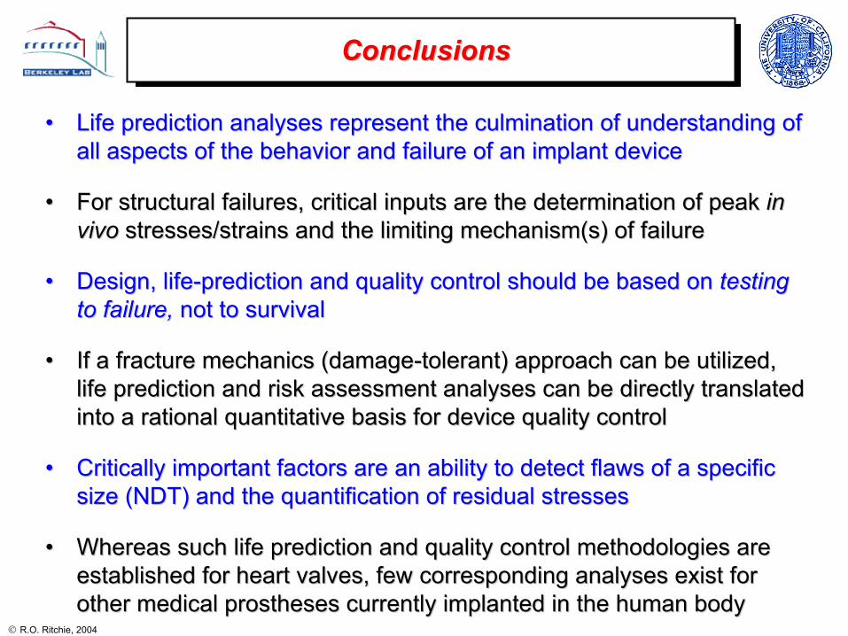
•• Life prediction analyses represent the culmination of understandLife prediction analyses represent the culmination of understanding of ing of all aspects of the behavior and failure of an implant deviceall aspects of the behavior and failure of an implant device
•• For structural failures, critical inputs are the determination oFor structural failures, critical inputs are the determination of peak f peak in in vivovivo stresses/strains and the limiting mechanism(s) of failurestresses/strains and the limiting mechanism(s) of failure
•• Design, lifeDesign, life--prediction and quality control should be based onprediction and quality control should be based on testing testing to failure, to failure, not to survivalnot to survival
•• If a fracture mechanics (damageIf a fracture mechanics (damage--tolerant) approach can be utilized, tolerant) approach can be utilized, life prediction and risk assessment analyses can be directly tralife prediction and risk assessment analyses can be directly translated nslated into a rational quantitative basis for device quality controlinto a rational quantitative basis for device quality control
•• Critically important factors are an ability to detect flaws of aCritically important factors are an ability to detect flaws of a specific specific size (NDT) and the quantification of residual stressessize (NDT) and the quantification of residual stresses
•• Whereas such life prediction and quality control methodologies aWhereas such life prediction and quality control methodologies are re established for heart valves, few corresponding analyses exist festablished for heart valves, few corresponding analyses exist for or other medical prostheses currently implanted in the human bodyother medical prostheses currently implanted in the human body
ConclusionsConclusions