Embed Size (px)
DESCRIPTION
254G2-404G2 Assembly instructions
Citation preview
Assembly of Devonn 254G2 + 304G2 Tractors
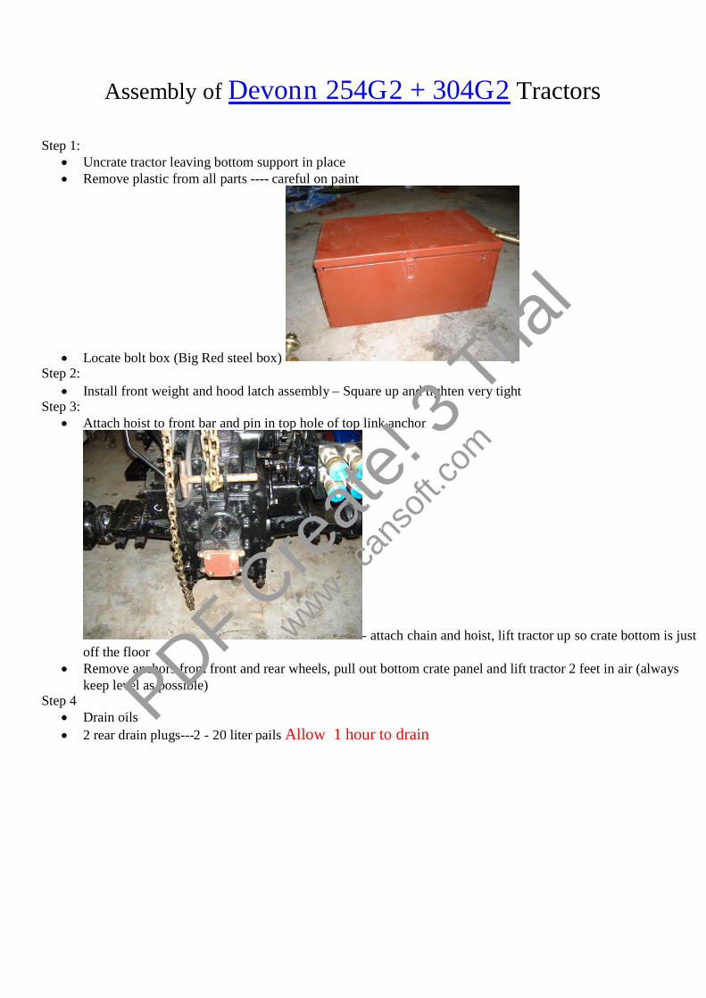
Step 1: Uncrate tractor leaving bottom support in place Remove plastic from all parts ---- careful on paint
Locate bolt box (Big Red steel box)Step 2:
Install front weight and hood latch assembly – Square up and tighten very tightStep 3:
Attach hoist to front bar and pin in top hole of top link anchor
- attach chain and hoist, lift tractor up so crate bottom is justoff the floor
Remove anchors from front and rear wheels, pull out bottom crate panel and lift tractor 2 feet in air (alwayskeep level as possible)
Step 4 Drain oils 2 rear drain plugs---2 - 20 liter pails Allow 1 hour to drain
PDF Cre
ate! 3
Tria
l
www.scan
soft.c
om
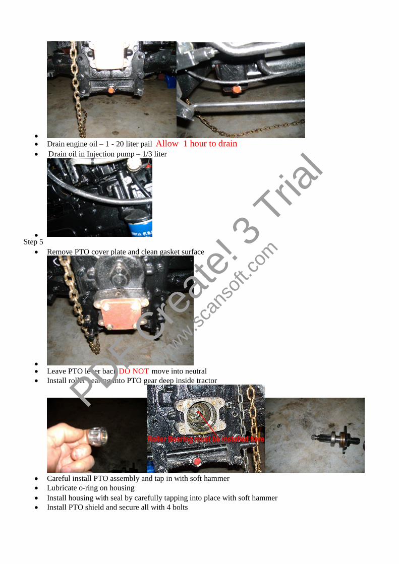
Drain engine oil – 1 - 20 liter pail Allow 1 hour to drain Drain oil in Injection pump – 1/3 liter
Step 5
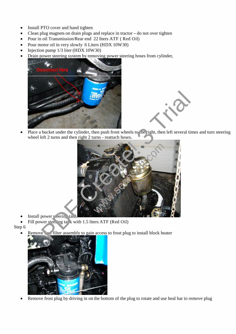
Remove PTO cover plate and clean gasket surface
Leave PTO lever back DO NOT move into neutral Install roller bearing into PTO gear deep inside tractor
Careful install PTO assembly and tap in with soft hammer Lubricate o-ring on housing Install housing with seal by carefully tapping into place with soft hammer Install PTO shield and secure all with 4 bolts
PDF Cre
ate! 3
Tria
l
www.scan
soft.c
om
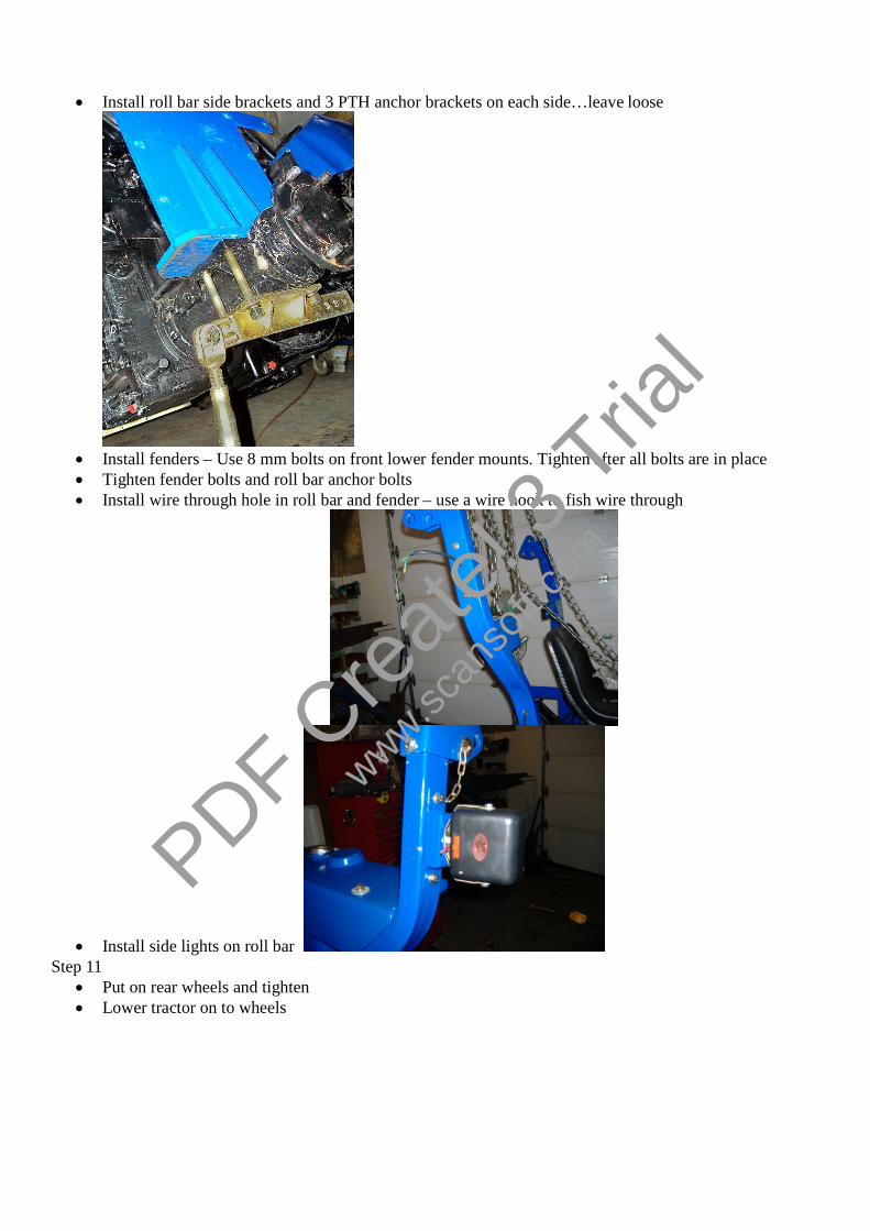
Install PTO cover and hand tighten Clean plug magnets on drain plugs and replace in tractor – do not over tighten Pour in oil Transmission/Rear end 22 liters ATF ( Red Oil) Pour motor oil in very slowly 6 Liters (HDX 10W30) Injection pump 1/3 liter (HDX 10W30) Drain power steering system by removing power steering hoses from cylinder,
Place a bucket under the cylinder, then push front wheels to the right, then left several times and turn steeringwheel left 2 turns and then right 2 turns - reattach hoses.
Install power steering tank Fill power steering tank with 1.5 liters ATF (Red Oil)
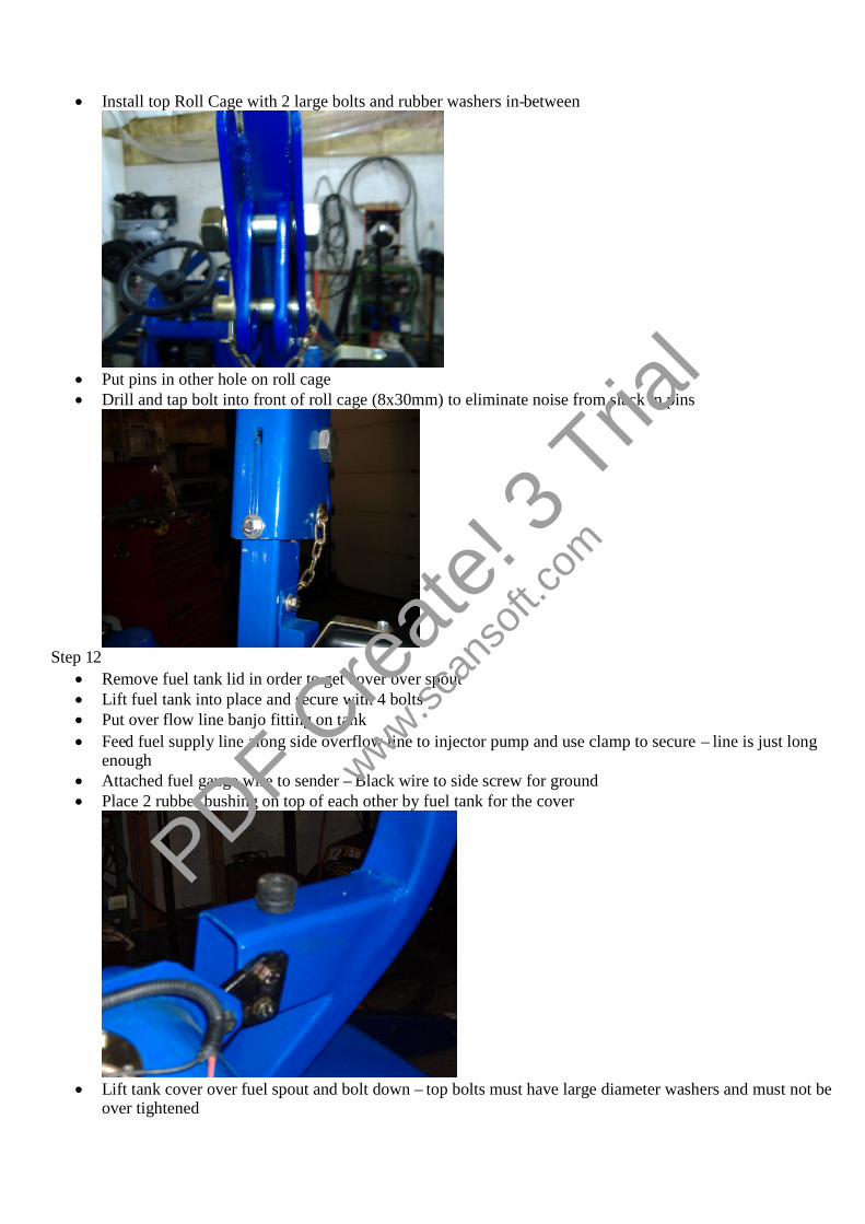
Step 6 Remove fuel filter assembly to gain access to frost plug to install block heater
Remove frost plug by driving in on the bottom of the plug to rotate and use heal bar to remove plug
PDF Cre
ate! 3
Tria
l
www.scan
soft.c
om

Clean and smooth hole with emery cloth, remove sharp edge to allow oring to slide in easier Put grease on o-ring and hole in block and carefully install heater (Temro #3100010) guiding o-ring with
screwdriver while pressing in on heater
Tighten screw in center of heater Fill cooling system with 10 liters 50/50 antifreeze Check for leaks Replace fuel filter assembly
Step 7 Install front tires and tighten Install steering wheel-grease spline and thread
Step 8 Remove hydraulic control levers from valve and bend 3 inches forward and reinstall Install Hydra control valve - make sure copper washers and the surfaces are CLEAN
Step 9 IMPORTANT – Will not fit later Clean 3 PTH anchor pin hole, then oil and install pin – watch 1 side larger than other – install small end first
from Right hand side of tractor, watch pin holes…keep them vertical – tap with soft hammer
Step 10 PDF Cre
ate! 3
Tria
l
www.scan
soft.c
om
Install roll bar side brackets and 3 PTH anchor brackets on each side…leave loose
Install fenders – Use 8 mm bolts on front lower fender mounts. Tighten after all bolts are in place Tighten fender bolts and roll bar anchor bolts Install wire through hole in roll bar and fender – use a wire hook to fish wire through
Install side lights on roll barStep 11
Put on rear wheels and tighten Lower tractor on to wheels
PDF Cre
ate! 3
Tria
l
www.scan
soft.c
om
Install top Roll Cage with 2 large bolts and rubber washers in-between
Put pins in other hole on roll cage Drill and tap bolt into front of roll cage (8x30mm) to eliminate noise from slack in pins
Step 12 Remove fuel tank lid in order to get cover over spout Lift fuel tank into place and secure with 4 bolts Put over flow line banjo fitting on tank Feed fuel supply line along side overflow line to injector pump and use clamp to secure – line is just long
enough Attached fuel gauge wire to sender – Black wire to side screw for ground Place 2 rubber bushing on top of each other by fuel tank for the cover
Lift tank cover over fuel spout and bolt down – top bolts must have large diameter washers and must not beover tightened
PDF Cre
ate! 3
Tria
l
www.scan
soft.c
om

Replace fuel cap Put fuel into tank (20 liters) Pump hand pump until you can hear fuel returning to tank – bleed screw on top of filter may have to be
loosened – fuel will come outStep 15
Install drawbar assembly on the 4 bolts on rear of tractor – tighten
Fit 3 PTH side arms and lift linkage Sway bar in center hole – Eyebolt on outside – Arm - thick washer - lock washer and nut Lift link in next hole forward Remove top link anchor 4 bolts and install top link storage bracket behind anchor - reinstall with same bolts
Step 16 Put LOCTITE on end threads of hood lift boosters and screw into ball joints on hood Lift and hold hood in place and attach boosters - up in the air Locate 4 -8mm bolts and secure rear of hood – Shims are required to align hood with dash – several tries may
be necessary Attach light wires and secure wire in brackets in hood
Step 17
PDF Cre
ate! 3
Tria
l
www.scan
soft.c
om

Remove clutch inspection cover on right side by brake pedals Look for PTO clutch adjustment screws (3 of them - 120 degrees apart on flywheel)
Feeler gauge required and thickness of .060 in or 1.50 mm Loosen lock nut and adjust to proper clearance - end of bolt to housing and retighten Check for release bearing touching all 3 fingers when free play is removed by pressing down clutch pedal They must all touch at the same time Notice the gear shift mechanism above and behind the clutch – good idea to squirt a small amount of oil into
this mechanism while moving gearshift levers. - Not so much as to get into clutch Reinstall cover
Step 18
Undo lock nut on main shift lever and remove knob Unscrew 6 screws from dash Grease 1 clutch and 2 brake pedals zerks Remove 4 screws from bellows seal on dash
PDF Cre
ate! 3
Tria
l
www.scan
soft.c
om

Check 2 screws on gear lever – Tighten and oil mechanism Reverse bellows so to point inwards and reattach – shifting is much smoother
Reinstall 6 screwsStep 19
Start engine – run at 1000 RPM for 5 minutes If engine is running a little rough at 1800 -2000 RPM the timing must be advanced 5 degrees
Put scribe mark on timing cover and on pump mount Loosen 3 screws on injection pump Twist pump on mount toward engine – watch to move only the thickness of your line
PDF Cre
ate! 3
Tria
l
www.scan
soft.c
om
Retighten pump – engine will run much smoother at higher RPM If everything is normal take tractor for a small drive, varying speeds and load…do not lug engine or rev high
(over 2000 RPM) for the first hour When engine is warmed up check the high RPM – Must be no more than 2400 RPM – Adjust injection pump
maximum speed screw to limit to 2400 RPM and reseal pump when finished If dynamometer is available engine should be run at least 2 hours before putting tractor on dyno Speed and load should be varied – never load for extended period at high RPM and maximum HP test should
be done for a very short period (2 minutes) 254G2 with ZN390T engine @ 2200 RPM should produce 30-32 HP 304G2 with ZN390T engine @ 2200 RPM should produce 35-36 HP
PDF Cre
ate! 3
Tria
l
www.scan
soft.c
om