Embed Size (px)
Citation preview

No.51951 May 2002
AV-32360 AV-32S36AV-32330 AV-32S33
AV-32320
1 COPYRIGHT © 2002 VICTOR COMPANY OF JAPAN, LTD.
AV-32360/M /R /Y AV-32S36/M /R /Y
AV-32330/M /R /Y AV-32S33/M /R /Y
AV-32320/M /R /Y
CONTENTS! SPECIFICATIONS ・・・・・・・・・・・・・・・・・・・・・・・・・・・・・・・・・・・・・・・・・・・・・・・・・・・・・・・・・・・・・・・・・・・・・・・・・・・・・・・・・・・・・・・・・・・・・・・・・・・・・・・・・・・・・・・・・・・・・・・・・・・・・・・・・・・・・・・・・・・・・・・・・・・・・・・・・・・・・・・・・・・・・・・・・・・・・・・・・・・・・・・・・・・・・・・・・・・・・・・・・・・・・・・・・・・・・・・・・・・・・・・・・・・・・・・・・・・・・・・・・・・・・・・・・・・・・・・・・・・・・・・・・・・・・・・・・・・・・・・・2! SAFETY PRECAUTIONS ・・・・・・・・・・・・・・・・・・・・・・・・・・・・・・・・・・・・・・・・・・・・・・・・・・・・・・・・・・・・・・・・・・・・・・・・・・・・・・・・・・・・・・・・・・・・・・・・・・・・・・・・・・・・・・・・・・・・・・・・・・・・・・・・・・・・・・・・・・・・・・・・・・・・・・・・・・・・・・・・・・・・・・・・・・・・・・・・・・・・・・・・・・・・・・・・・・・・・・・・・・・・・・・・・・・・・・・・・・・・・・・・・・・・・・・・・・・・・・・・・・・・・・・・・・・・・・・・3
! FEATURES・・・・・・・・・・・・・・・・・・・・・・・・・・・・・・・・・・・・・・・・・・・・・・・・・・・・・・・・・・・・・・・・・・・・・・・・・・・・・・・・・・・・・・・・・・・・・・・・・・・・・・・・・・・・・・・・・・・・・・・・・・・・・・・・・・・・・・・・・・・・・・・・・・・・・・・・・・・・・・・・・・・・・・・・・・・・・・・・・・・・・・・・・・・・・・・・・・・・・・・・・・・・・・・・・・・・・・・・・・・・・・・・・・・・・・・・・・・・・・・・・・・・・・・・・・・・・・・・・・・・・・・・・・・・・・・・・・・・・・・・・・・・・・・・・・・・・・・・・・・・・・・・4
! FUNCTIONS ・・・・・・・・・・・・・・・・・・・・・・・・・・・・・・・・・・・・・・・・・・・・・・・・・・・・・・・・・・・・・・・・・・・・・・・・・・・・・・・・・・・・・・・・・・・・・・・・・・・・・・・・・・・・・・・・・・・・・・・・・・・・・・・・・・・・・・・・・・・・・・・・・・・・・・・・・・・・・・・・・・・・・・・・・・・・・・・・・・・・・・・・・・・・・・・・・・・・・・・・・・・・・・・・・・・・・・・・・・・・・・・・・・・・・・・・・・・・・・・・・・・・・・・・・・・・・・・・・・・・・・・・・・・・・・・・・・・・・・・・・・・・・・・・・・・・・・・・・・・・4! MAIN DIFFERENCE LIST ・・・・・・・・・・・・・・・・・・・・・・・・・・・・・・・・・・・・・・・・・・・・・・・・・・・・・・・・・・・・・・・・・・・・・・・・・・・・・・・・・・・・・・・・・・・・・・・・・・・・・・・・・・・・・・・・・・・・・・・・・・・・・・・・・・・・・・・・・・・・・・・・・・・・・・・・・・・・・・・・・・・・・・・・・・・・・・・・・・・・・・・・・・・・・・・・・・・・・・・・・・・・・・・・・・・・・・・・・・・・・・・・・・・・・・・・・・・・・・・・・・・・・・・・・・・・・・・・6
! HOW TO INDENTIFY MODELS・・・・・・・・・・・・・・・・・・・・・・・・・・・・・・・・・・・・・・・・・・・・・・・・・・・・・・・・・・・・・・・・・・・・・・・・・・・・・・・・・・・・・・・・・・・・・・・・・・・・・・・・・・・・・・・・・・・・・・・・・・・・・・・・・・・・・・・・・・・・・・・・・・・・・・・・・・・・・・・・・・・・・・・・・・・・・・・・・・・・・・・・・・・・・・・・・・・・・・・・・・・・・・・・・・・・・・・・・・・・・・・・・・・・・・・・・・・・・・・・7
! SPECIFIC SERVICE INSTRUCTIONS ・・・・・・・・・・・・・・・・・・・・・・・・・・・・・・・・・・・・・・・・・・・・・・・・・・・・・・・・・・・・・・・・・・・・・・・・・・・・・・・・・・・・・・・・・・・・・・・・・・・・・・・・・・・・・・・・・・・・・・・・・・・・・・・・・・・・・・・・・・・・・・・・・・・・・・・・・・・・・・・・・・・・・・・・・・・・・・・・・・・・・・・・・・・・・・・・・・・・・・・・・・・・・・・・・・・・・・・・8! SERVICE ADJUSTMENTS ・・・・・・・・・・・・・・・・・・・・・・・・・・・・・・・・・・・・・・・・・・・・・・・・・・・・・・・・・・・・・・・・・・・・・・・・・・・・・・・・・・・・・・・・・・・・・・・・・・・・・・・・・・・・・・・・・・・・・・・・・・・・・・・・・・・・・・・・・・・・・・・・・・・・・・・・・・・・・・・・・・・・・・・・・・・・・・・・・・・・・・・・・・・・・・・・・・・・・・・・・・・・・・・・・・・・・・・・・・・・・・・・・・・・・・・・・・・・・・・・・・・・・・・・14
! PARTS LIST ・・・・・・・・・・・・・・・・・・・・・・・・・・・・・・・・・・・・・・・・・・・・・・・・・・・・・・・・・・・・・・・・・・・・・・・・・・・・・・・・・・・・・・・・・・・・・・・・・・・・・・・・・・・・・・・・・・・・・・・・・・・・・・・・・・・・・・・・・・・・・・・・・・・・・・・・・・・・・・・・・・・・・・・・・・・・・・・・・・・・・・・・・・・・・・・・・・・・・・・・・・・・・・・・・・・・・・・・・・・・・・・・・・・・・・・・・・・・・・・・・・・・・・・・・・・・・・・・・・・・・・・・・・・・・・・・・・・・・・・・・・・・・・・・・・・・・・・・35
★ STANDARD CIRCUIT DIAGRAM ・・・・・・・・・・・・・・・・・・・・・・・・・・・・・・・・・・・・・・・・・・・・・・・・・・・・・・・・・・・・・・・・・・・・・・・・・・・・・・・・・・・・・・・・・・・・・・・・・・・・・・・・・・・・・・・・・・・・・・・・・・・・・・・・・・・・・・・・・・・・・・・・・・・・・・・・・・・・・・・・・・・・・・・・・・・・・・・・・・・・・・・・・・・・・・・・・・・・・・・・・・・・・・・・・・・・・・・・・・・・・・・・ 2-1
SERVICE MANUALCOLOR TELEVISION
BASIC CHASSIS
GE
[RM-C254]AV-32360AV-32S36
[RM-C255]AV-32330AV-32S33 [RM-C205]
AV-32320
No.51950
AV-36360 AV-36S36AV-36330 AV-36S33AV-36320
2
SPECIFICATIONSCONTENTS
ITEMS AV-36360/M /R
AV-36S36/M /RAV-36330/M /R
AV-36S33/M /R AV-36320/M /R
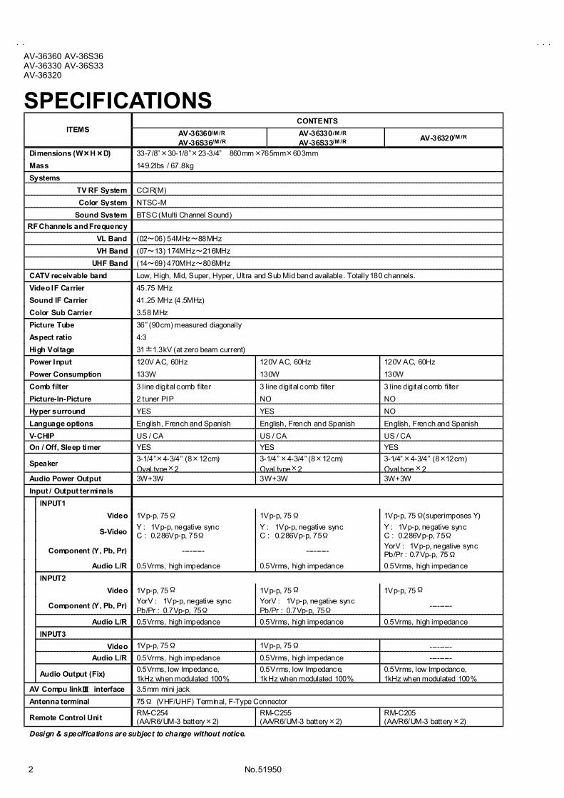
Dimensions (W××××H××××D) 33-7/8�×30-1/8�×23-3/4� 860mm×765mm×603mm
Mass 149.2Ibs / 67.8kg
Systems
TV RF System CCIR(M)
Color System NTSC-M
Sound System BTSC (Multi Channel Sound)
RF Channels and Frequency
VL Band (02~06) 54MHz~88MHz
VH Band (07~13) 174MHz~216MHz
UHF Band (14~69) 470MHz~806MHz
CATV receivable band Low, High, Mid, Super, Hyper, Ultra and Sub Mid band available. Totally 180 channels.
Video IF Carrier 45.75 MHz
Sound IF Carrier 41.25 MHz (4.5MHz)
Color Sub Carrier 3.58 MHz
Picture Tube 36� (90cm) measured diagonally
Aspect ratio 4:3
High Voltage 31±1.3kV (at zero beam current)
Power Input 120V AC, 60Hz 120V AC, 60Hz 120V AC, 60Hz
Power Consumption 133W 130W 130W
Comb filter 3 line digital comb filter 3 line digital comb filter 3 line digital comb filter
Picture-In-Picture 2 tuner PIP NO NO
Hyper surround YES YES NO
Language options English, French and Spanish English, French and Spanish English, French and Spanish
V-CHIP US / CA US / CA US / CA
On / Off, Sleep timer YES YES YES
Speaker3-1/4�×4-3/4� (8×12cm)Oval type×2
3-1/4�×4-3/4� (8×12cm)Oval type×2
3-1/4�×4-3/4� (8×12cm)Oval type×2
Audio Power Output 3W+3W 3W+3W 3W+3W
Input / Output terminals
INPUT1
Video 1Vp-p, 75Ω 1Vp-p, 75Ω 1Vp-p, 75Ω(superimposes Y)
S-VideoY : 1Vp-p, negative syncC : 0.286Vp-p, 75Ω
Y : 1Vp-p, negative syncC : 0.286Vp-p, 75Ω
Y : 1Vp-p, negative syncC : 0.286Vp-p, 75Ω
Component (Y, Pb, Pr) --------- ---------YorV : 1Vp-p, negative syncPb/Pr : 0.7Vp-p, 75Ω
Audio L/R 0.5Vrms, high impedance 0.5Vrms, high impedance 0.5Vrms, high impedance
INPUT2
Video 1Vp-p, 75Ω 1Vp-p, 75Ω 1Vp-p, 75Ω
Component (Y, Pb, Pr)YorV : 1Vp-p, negative syncPb/Pr : 0.7Vp-p, 75Ω
YorV : 1Vp-p, negative syncPb/Pr : 0.7Vp-p, 75Ω
---------
Audio L/R 0.5Vrms, high impedance 0.5Vrms, high impedance 0.5Vrms, high impedance
INPUT3
Video 1Vp-p, 75Ω 1Vp-p, 75Ω ---------
Audio L/R 0.5Vrms, high impedance 0.5Vrms, high impedance ---------
Audio Output (Fix)0.5Vrms, low Impedance,1kHz when modulated 100%
0.5Vrms, low Impedance,1kHz when modulated 100%
0.5Vrms, low Impedance,1kHz when modulated 100%
AV Compu linkⅢⅢⅢⅢ interface 3.5mm mini jack
Antenna terminal 75Ω (VHF/UHF) Terminal, F-Type Connector
Remote Control UnitRM-C254(AA/R6/UM-3 battery×2)
RM-C255(AA/R6/UM-3 battery×2)
RM-C205(AA/R6/UM-3 battery×2)
Design & specifications are subject to change without notice.

No. 51950
AV-36360 AV-36S36AV-36330 AV-36S33
AV-36320
3
SAFETY PRECAUTIONS1. The design of this product contains spec ial hardware, many
circuits and components specially for safety purposes. Forcontinued protection, no changes should be made to theoriginal des ign unless authorized in writing by the manufacturer.Replacement parts must be ident ical to those used in theoriginal circuits. Service should be performed by qualifiedpersonnel only.
2. Alterations of the design or circuitry of the products should notbe made. Any design alterations or additions will void themanufacturer's warranty and will further relieve themanufacturer of respons ibility for personal injury or propertydamage result ing therefrom.
3. Many electrical and mechanical parts in the products havespecial safety-related characteris tics. These charac teristics areoften not evident from visual inspection nor can the protectionafforded by them necessarily be obtained by usingreplacement components rated for higher voltage, wattage, etc.Replacement parts which have these special safetycharacteristics are identified in the parts list of Service manual.Electrical components having such features are identifiedby shading on the schematics and by (!!!!) on the parts listin Service manual. The use of a subst itute replacement whichdoes not have the same safety characterist ics as therecommended replacement part shown in the parts list ofService manual may cause shock, f ire, or other hazards.
4. Use isolation transformer when hot chassis.The chassis and any sub-chassis contained in some productsare connected to one side of the AC power line. An isolationtransformer of adequate capacity should be inserted betweenthe product and the AC power supply point while performingany service on some products when the HOT chassis isexposed.
5. Do n't short between the LIVE side ground and ISOLATED(NEUTRAL) side ground or EARTH side ground whenrepairing.Some model's power c ircuit is part ly dif ferent in the GND. Thedifference of the GND is shown by the LIVE : (") s ide GND,the ISOLATED(NEUTRAL) : (#) side GND and EARTH : ($)side GND. Don't short between the LIVE side GND andISOLATED(NEUTRAL) side GND or EARTH side GND andnever measure with a measuring apparatus (oscilloscope etc.)the LIVE side GND and ISOLATED(NEUTRAL) side GND orEARTH side GND at the same time.If above note will not be kept, a fuse or any parts will be broken.
6. If any repair has been made to the chassis, it is recommendedthat the B1 setting should be checked or adjusted (SeeADJUSTMENT OF B1 POWER SUPPLY).
7. The high voltage applied to the picture tube must conform withthat specified in Service manual. Excessive high voltage cancause an increase in X-Ray emission, arc ing and possiblecomponent damage, therefore operation under excess ive highvoltage condit ions should be kept to a minimum, or should beprevented. I f severe arc ing occurs, remove the AC powerimmediately and determine the cause by visual inspection(incorrect installation, cracked or melted high voltage harness,poor soldering, etc.). T o maintain the proper minimum level ofsoft X-Ray emission, components in the high voltage circuitryincluding the picture tube must be the exact replacements oralternat ives approved by the manufacturer of the completeproduct.
8. Do not check high voltage by drawing an arc. Use a highvoltage meter or a high voltage probe with a VTVM. Dischargethe picture tube before attempting meter connection, byconnec ting a clip lead to the ground frame and connecting theother end of the lead through a 10kΩ 2W resistor to the anodebutton.
9. When service is required, observe the original lead dress.Extra precaution should be given to assure correct lead dressin the high voltage c ircuit area. W here a short circuit hasoccurred, those components that indicate evidence ofoverheating should be replaced. Always use themanufacturer's replacement components.
10. Isolation Check(Safety for Electrical Shock Hazard)After re-assembling the product, always perform an isolationcheck on the exposed metal parts of the cabinet (antennaterminals, video/audio input and output terminals, Controlknobs, metal cabinet, screwheads, earphone jack, controlshafts, etc.) to be sure the product is safe to operate withoutdanger of electrical shock.
(1) Dielectric Strength TestThe isolat ion between the AC primary circuit and all metal partsexposed to the user, part icularly any exposed metal part havinga return path to the chassis should withstand a voltage of1100V AC (r.m.s.) for a period of one second.(. . . . Withs tand a voltage of 1100V AC (r.m.s.) to an appliancerated up to 120V, and 3000V AC (r.m.s.) to an appliance rated200V or more, for a period of one second.)This method of test requires a test equipment not generallyfound in the service trade.
(2) Leakage Current CheckPlug the AC line cord direct ly into the AC outlet (do not use aline isolation transformer during this check.). Using a "LeakageCurrent Tester", measure the leakage current from eachexposed metal part of the cabinet, particularly any exposedmetal part having a return path to the chassis , to a known goodearth ground (water pipe, etc.). Any leakage current must notexceed 0.5mA AC (r.m.s.).However, in t ropical area, this must not exceed 0.2mA AC(r.m.s.)."""" Alternate Check MethodPlug the AC line cord direct ly into the AC outlet (do not use aline isolation transformer during this check.). Use an ACvoltmeter having 1000 ohms per volt or more sensitivity in thefollowing manner. Connec t a 1500Ω 10W resistor paralleledby a 0.15μF AC-type capacitor between an exposed metalpart and a known good earth ground (water pipe, etc.).Measure the AC voltage across the resistor with the ACvoltmeter. Move the res istor connection to each exposed metalpart , part icularly any exposed metal part having a return path tothe chassis , and measure the AC voltage across the resistor.Now, reverse the plug in the AC out let and repeat eachmeasurement. Any voltage measured must not exceed 0.75VAC (r.m.s.). This corresponds to 0.5mA AC (r.m.s.).However, in tropical area, this must not exceed 0.3V AC(r.m.s.). This corresponds to 0.2mA AC (r.m.s.).
0.15μF AC-TYPE
1500Ω 10W
GOODEARTHGROUND
PLACE THIS PROBEON EACH EXPOSEDMETAL PART
AC VOLTMETER(HAVING 1000Ω/V,OR MORE SENSITIVITY)
11. High voltage hold down circuit check.After repair of the high voltage hold down circuit, this circuitshall be checked to operate correctly.See item "Ho w to check the high voltage hold downcircuit".
A V
This mark shows a fastoperating fuse, theletters indicated belowshow the rating.

No. 51950
AV-36360 AV-36S36AV-36330 AV-36S33AV-36320
4
FEATURES" Title TELE-TEXT broadcast of C1, C2, T1, and T2 formula is receivable." The voice multiplex function of the MTS system is built in." By the EZ SURF func tion, channel ID and a program name are displayed in the screen automatically [Only for AV-36360 and AV-36S36].
" By the COMPU LINK Ⅲ function, operation interlocked with the DVD deck can be performed from remote control.
" By the three-line digital comb filter, the refreshed image can be seen." Two programs can be displayed on the screen by the 2 tuner PIP circuit [Only for AV-36360 and AV-36S36]." Expression of a favorite screen can be chosen by the VIDEO STATUS function." A program can be enjoyed with a powerful sound by the HYPER SURROUND function [Except AV-36320]." Since the V chip is built in, it can choose, view and listen to a healthy program." The RETURN PLUS funct ion is built in." A quick favorite program can be looked for by the HYPER-SCAN function." Since the component signal input terminal is equipped, it reappears direct without deteriorating the signal from DVD,.
FUNCTIONS
① MENU KEY, SELECT ▼ KEY
②CHANNEL -/+ KEYSOPERATE / KEYS
③ VOLUME -/+ KEY
④ POWER KEY
⑤ ON TIMER / POWER LED
⑥ REMOCON WINDOW
AV-36360, 36330, 36S36, 36S33 INPUT 3 TERMINAL (V / L / R)⑦
AV-36320 INPUT 2 TERMINAL (V / L / R)
FRONT PANEL CONTROLS
1 4 5 6
7
2 3

No. 51950
AV-36360 AV-36S36AV-36330 AV-36S33
AV-36320
5
[RM-C254, 255] [RM-C205]
REMOTE CONTROL UNIT (RM-C254, RM-C255, RM-C205)
1
2
4
5
6
7
8
9
10
3
11
12
13
14
15
18
1617
[AV-36360, 36S36, 36330, 36S33]
[AV-36320]
REAR TERMINAL
1
2 6
7
8
12
3
4
5
9
10
13
11
1
2
3
4
6
1
3
5
6
① ①INPUT 1
S-VIDEO, V, L, R
② ------INPUT 2
L, R
③ ③AUDIO OUT (FIXED)
L, R
④ ------INPUT 2
COMPONENTVIDEO or Y, PB, PR
------ ⑤INPUT 1
COMPONENTVIDEO or Y, PB, PR
⑥ ⑥ANTENNA SOCKET
F-Type
AV-36360AV-36S33AV-36330AV-36S33
AV-36320 FUNCTION
RM-C254RM-C255 RM-C205 FUNCTION
② ------ TV / CATV
③ ------ EZ SURF[Only for RM-C254]
④ ⑦ INPUT⑤ ③ DISPLAY⑥ ① SLEEP TIMER⑦ ------ HYPER SURROUND
⑧ ② VIDEO STATUS
⑨ ④ MUTING
⑩ ⑤ MENU
⑪ ⑥ POWER
⑫ ------ PIP CONTROL[Only for RM-C254]
⑬ ⑧ CHANNEL NUMBER
⑭ ⑨ V-CHIP
⑮ ⑩ EXIT
⑯ ⑪VOLUME -/+ andCURSOR /
⑰ ⑫CHANNEL +/- andCURSOR ▲/▼
⑱ ⑬ VCR CONTROL
① ------ VCR / DVD

No. 51950
AV-36360 AV-36S36AV-36330 AV-36S33AV-36320
6
MAIN DIFFERENCE LISTPARTS NAME MODEL /M /R
ITC TUBE (Inc. DY, P C MAGNET, WEDGE) A90LLD361X15 A90AEJ15X01
DEG COIL QQW0106-001or QQW0114-001
CELD067-001JAor QQW0136-001
MAIN PWB SGE-1008A-M2 SGE-1032A-M2
CRT SOCKET PWB SGE-3003A-M2 SGE-3011A-M2
PIP PWB SGE-4001A-M2
AV SELECTOR PWB SGE-5002A-M2
E-COAXIAL ASSY WJX0014-002A
TERMINAL BOARD LC20899-006A-A
TAP SCREW (for TERM. BOARD) QYSBSB3010Z (×4)
PUSH KNOB CM35776-B01-H
BRAND MARK CM46084-A01
FRONT CABI. ASSY CM12747-A0G-MA
DOOR CM36162-005-A
REMOCON UNIT
AV-36360
[BLACK]
RM-C254-1H
ITC TUBE (Inc. DY, P C MAGNET, WEDGE) A90LLD361X15 A90AEJ15X01
DEG COIL QQW0106-001or QQW0114-001
CELD067-001JAor QQW0136-001
MAIN PWB SGE-1011A-M2 SGE-1041A-M2
CRT SOCKET PWB SGE-3003A-M2 SGE-3011A-M2
PIP PWB × ×
AV SELECTOR PWB SGE-5002A-M2
E-COAXIAL ASSY × ×
TERMINAL BOARD LC20899-006A-A
TAP SCREW (for TERM. BOARD) QYSBSB3010Z (×4)
PUSH KNOB CM35776-B01-H
BRAND MARK CM46084-A01
FRONT CABI. ASSY CM12747-A0G-MA
DOOR CM36162-005-A
REMOCON UNIT
AV-36330
[BLACK]
RM-C255-1H
ITC TUBE (Inc. DY, P C MAGNET, WEDGE) A90LLD361X15 A90AEJ15X01
DEG COIL QQW0106-001or QQW0114-001
CELD067-001JAor QQW0136-001
MAIN PWB SGE-1014A-M2 SGE-1047A-M2
CRT SOCKET PWB SGE-3003A-M2 SGE-3011A-M2
PIP PWB × ×
AV SELECTOR PWB SGE-5003A-M2
E-COAXIAL ASSY × ×
TERMINAL BOARD LC20899-007A-A
TAP SCREW (for TERM. BOARD) QYSBSB3010Z (×3)
PUSH KNOB CM35776-B01-H
BRAND MARK CM46084-A01
FRONT CABI. ASSY CM12747-A0G-MA
DOOR CM36162-005-A
REMOCON UNIT
AV-36320
[BLACK]
RM-C205-1C

No. 51950
AV-36360 AV-36S36AV-36330 AV-36S33
AV-36320
7
PARTS NAME MODEL /M /R
ITC TUBE (Inc. DY, P C MAGNET, WEDGE) A90LLD361X15 A90AEJ15X01
DEG COIL QQW0106-001or QQW0114-001
CELD067-001JAor QQW0136-001
MAIN PWB SGE-1008A-M2 SGE-1032A-M2
CRT SOCKET PWB SGE-3003A-M2 SGE-3011A-M2
PIP PWB SGE-4001A-M2
AV SELECTOR PWB SGE-5002A-M2
E-COAXIAL ASSY WJX0014-002A
TERMINAL BOARD LC20899-006A-A
TAP SCREW (for TERM. BOARD) QYSBSB3010Z (×4)
PUSH KNOB CM35776-005-H
BRAND MARK CM46084-002
FRONT CABI. ASSY CM12747-00S-MA
DOOR CM36162-014-A
REMOCON UNIT
AV-36S36
[SILVER]
RM-C254-1H
ITC TUBE (Inc. DY, P C MAGNET, WEDGE) A90LLD361X15 A90AEJ15X01
DEG COIL QQW0106-001or QQW0114-001
CELD067-001JAor QQW0136-001
MAIN PWB SGE-1011A-M2 SGE-1041A-M2
CRT SOCKET PWB SGE-3003A-M2 SGE-3011A-M2
PIP PWB × ×
AV SELECTOR PWB SGE-5002A-M2
E-COAXIAL ASSY × ×
TERMINAL BOARD LC20899-006A-A
TAP SCREW (for TERM. BOARD) QYSBSB3010Z (×4)
PUSH KNOB CM35776-005-H
BRAND MARK CM46084-002
FRONT CABI. ASSY CM12747-00S-MA
DOOR CM36162-014-A
REMOCON UNIT
AV-36S33
[SILVER]
RM-C255-1H
HOW TO IDENTIFY MODELSHow to recognize from the appearance of the model concerned is written below. Please dist inguish from several contents currently printed onthe rat ing label.
Model Name Detailed Model Number
AV-36360 /M M
AV-36360 /RAV-36360
R
AV-36330 /M M
AV-36330 /RAV-36330
R
AV-36230 /M M
AV-36230 /RAV-36320
R
AV-36S36 /M M
AV-36S36 /RAV-36S36
R
AV-36S33 /M M
AV-36S33 /RAV-36S33
R
Model Name
Detailed Model Name
No. 51950
AV-36360 AV-36S36AV-36330 AV-36S33AV-36320
8
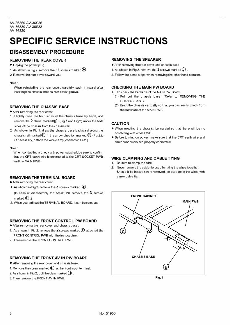
SPECIFIC SERVICE INSTRUCTIONSDISASSEMBLY PROCEDURE
REMOVING THE REAR COVER" Unplug the power plug.
1. As shown in Fig.2, remove the 11 screws marked !!!! .
2. Remove the rear cover toward you.
Note :
When reinstalling the rear cover, carefully push it inward afterinserting the chassis into the rear cover groove.
REMOVING THE CHASSIS BASE" After removing the rear cover.
1. Slight ly raise the both s ides of the chassis base by hand, and
remove the 2 claws marked """" (Fig.1 and Fig.2) under the both
sides of the chassis from the chassis rail. 2. As shown in Fig.1, draw the chassis base backward along the
chassis rail marked #### in the arrow direction marked $$$$(Fig.2.).
(If necessary, detach the wire clamp, connec tor�s etc.)
Note :When conducting a check with power supplied, be sure to conf irmthat the CRT earth wire is connected to the CRT SOCKET PWB
and the MAIN PWB.
REMOVING THE TERMINAL BOARD" After removing the rear cover.
1. As shown in Fig.2, remove the 4 screws marked%&%&%&%& .
(In case of disassembly the AV-36320, remove the 3 screws
marked &&&&.) 2. When you pull out the TERMINAL BOARD, it can be removed.
REMOVING THE FRONT CONTROL PW BOARD" After removing the rear cover and chassis base .
1. As shown in Fig.2, remove the 2 screws marked ''''attached the
FRONT CONTROL PWB with the front cabinet.
2. Then remove the FRONT CONTROL PWB.
REMOVING THE FRONT AV IN PW BOARD" After removing the rear cover and chassis base.
1. Remove the screw marked (((( at the front input terminal.
2. As shown in Fig.2, pull the claw marked )))) . 3. Then remove the FRONT AV IN PWB.
REMOVING THE SPEAKER" After removing the rear cover and chassis base.
1. As shown in Fig.2, r emove the 2 screws marked **** .
2. Follow the same steps when removing the other hand speaker.
CHECKING THE MAIN PW BOARD1. To check the backs ide of the MAIN PW Board.
(1) Pull out the chassis base. (Refer to REMOVING THE
CHASSIS BASE).(2) Erect the chassis vertically so that you can easily check from
the backside of the MAIN PWB.
CAUTION" When erecting the chass is, be careful so that there will be no
contact ing with other PWB." Before turning on power, make sure that the CRT earth wire and
other connectors are properly connected.
WIRE CLAMPING AND CABLE TYING1. Be sure to clamp the wire.
2. Never remove the cable tie used for tying the wires together.Should it be inadvertent ly removed, be sure to t ie the wires with
a new cable tie.
CHASSIS BASE
Fig. 1
C
B
FRONT CABINET
MAIN PWB

No. 51950
AV-36360 AV-36S36AV-36330 AV-36S33
AV-36320
9
FRONT CABINET
CRT
SPEAKER
CLAW
FRONT AV INPWB
CRT SOCKET PWB
POWER CORD
FRONT CONTROL PWB
SPEAKER
CLAW
AV SELECTORPWB
PIP PWB[Only for AV-36360 and AV-36S36]
TERMINAL BOARD
HVT
CHASSIS BASE
REAR COVER
MAIN PWB
J
J
B
B
D
E
A
Fig.2
This illustration describes about AV-36360.Although the other models are slightly dif ferent
from this illustration, it can use for the other models
in the same steps as this illustration.
No te
F
HCLAW
G

No. 51950
AV-36360 AV-36S36AV-36330 AV-36S33AV-36320
10
MEMORY IC REPLACEMENT
1. Memory ICThis model uses the memory IC.This memory IC stores data for proper operation of the video/chroma and deflection circuits.
When replacing, be sure to use the IC containing initial setting data.
2. Memory IC replacement procedure(1) Power off
Switch off the power and disconnec t the power plug from the AC outlet.
(2) Replace the memory ICBe sure to use the memory IC writ ten with the initial setting values.
(3) Power onConnect the power plug to the AC outlet and switch on the power.
(4) System constant check and setting① Press the SLEEP TIMER key and set SLEEP TIMER for 「0 min」.
② Before disappear the display of SLEEP TIMER sett ings, simultaneouslypress the DISPLAY key and VIDEO ST ATUS key of the remote control unit.The SERVICE MENU screen of Fig.1 will be displayed.
③ While the SERVICE MENU is displayed, select the SYSTEM(SYS) item
with CURSOR ▼/▲ key and go into with / keys. Then the SYSTEM
mode screen will be displayed as shown in Fig.2.
④ Refer to the table of SYSTEM CONSTANT given in page later, and check
the each item. If the value is different, select the setting item with the
CURSOR ▼/▲ key, and setting with the CURSOR / keys. (The let ters
of the selec ted item is displayed in yellow.)
⑤ When adjustment has completed, the values store into memory IC
automatically.⑥ Press the EXIT key twice to return to the normal screen.
(5) Receiving channel settingRefer to the OPERATING INSTRUCTIONS and set the receivechannels (Channels Preset) as described.
(6) User settingsCheck the user setting items according to the Table 2 given in pagelater.Where these do not agree, refer to the OPERAT INGINSTRUCT IONS and set the items as described.
(7) SERVICE MENU settingVerify what to set in the SERVICE MENU, and set whatever isnecessary (Fig.1). Refer to the SERVICE ADJUSTMENT for setting.
SERVICE MENU
SERVICE MENU
1.V/C(S) 2.D EF(D)3.SOUND(A) 4.OTHERS5.PIP(PIP) 6.3L Y/C(LYC)7.LOW LIGHT 8.HIGH LIGHT9.RF AFC 1 0.VCO11.I2C BUS 12.SYSTEM(SYS)
SELECT BYOPERATE B Y EXIT BY EXIT
Fig.1
12. SYSTEM (SYS) MODE
***SYS0 1 VIDEO
Fig.2
KEY ASSIGNMENT OF REMOTE CONTROL UNIT
EXIT fromSYSTEM mode
Although this illus tration of remote control unit is written aboutRM-C254 (AV-36360), it can use for operating the other model
of remote control unit as same key assignment.
②
Simultaneously push
③
Go into the item
④
Setting the value
③, ④Select the item
①
Setting for �0 min�

No. 51950
AV-36360 AV-36S36AV-36330 AV-36S33
AV-36320
11
VALUES OF SYSTEM CONSTANT (TABLE 1)
INITIAL SETTING VALUEITEM CONT ENTS
VARIABLERANGE AV-36360 AV-36S36 AV-36330 AV-36S33 AV-36320
SYS01 VIDEO IN 0~4 3 3 3 3 2
SYS02 PIP 0~1 1 1 0 0 0
SYS03 3D Y/C 0~1 0 0 0 0 0
SYS04 Y CV 0~1 0 0 0 0 0
SYS05 CCD PCHK 0~1 1 1 1 1 1
SYS06 PURITY 0~1 0 0 0 0 0
SYS07 VM 0~1 0 0 0 0 0
SYS08 NOISE CR 0~1 0 0 0 0 0
SYS09 CLR TEMP 0~1 0 0 0 0 0
SYS10 THEATER 0~1 0 0 0 0 0
SYS11 THEATER PRO 0~1 0 0 0 0 0
SYS12 BBE 0~1 0 0 0 0 0
SYS13 HYP SURR 0~1 1 1 1 1 0
SYS14 16:9 MD 0~1 0 0 0 0 0
SYS15 HYP SCAN 0~1 1 1 1 1 1
SYS16 EZ SURF 0~1 1 1 0 0 0
SYS17 ID DISP 0~1 1 1 1 1 0
SYS18 COMPULINK 0~1 0 0 0 0 0
SYS19 CCD 0~1 1 1 1 1 1
SYS20 VCHIP 0~1 1 1 1 1 1
SYS21 VCHIP CA 0~1 1 1 1 1 1
SYS22 JVC LOGO 0~1 1 1 1 1 1
SYS23 CMP IN 0~1 1 1 1 1 0
SYS24 CXA1875 0~1 0 0 0 0 0
No. 51950
AV-36360 AV-36S36AV-36330 AV-36S33AV-36320
12
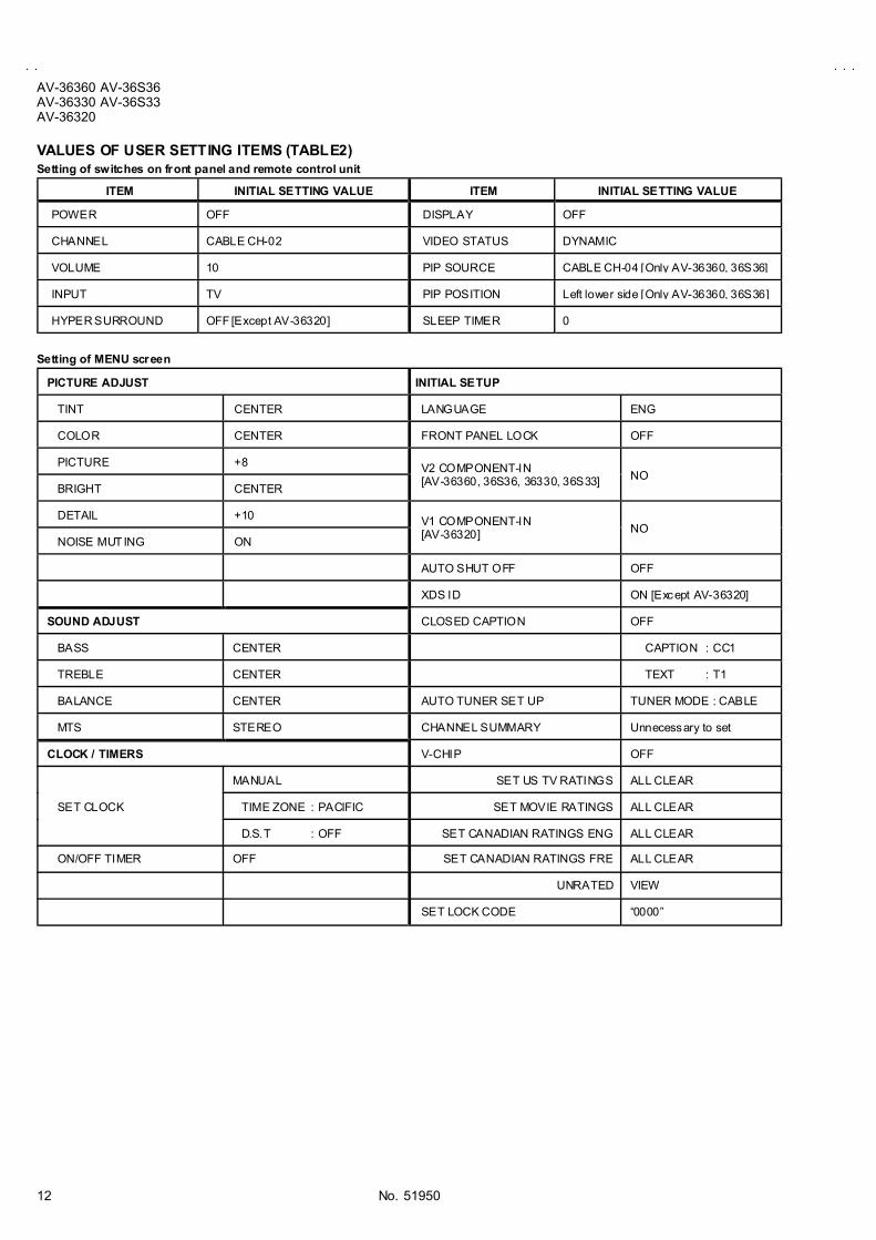
VALUES OF USER SETTING ITEMS (TABLE2)Setting of switches on front panel and remote control unit
ITEM INITIAL SETTING VALUE ITEM INITIAL SETTING VALUE
POWER OFF DISPLAY OFF
CHANNEL CABLE CH-02 VIDEO STATUS DYNAMIC
VOLUME 10 PIP SOURCE CABLE CH-04 [Only AV-36360, 36S36]
INPUT TV PIP POSITION Left lower side [Only AV-36360, 36S36]
HYPER SURROUND OFF [Except AV-36320] SLEEP TIMER 0
Setting of MENU screen
PICTURE ADJUST INITIAL SETUP
TINT CENTER LANGUAGE ENG
COLOR CENTER FRONT PANEL LOCK OFF
PICTURE +8
BRIGHT CENTER
V2 COMPONENT-IN[AV-36360, 36S36, 36330, 36S33] NO
DETAIL +10
NOISE MUT ING ON
V1 COMPONENT-IN[AV-36320] NO
AUTO SHUT OFF OFF
XDS ID ON [Except AV-36320]
SOUND ADJUST CLOSED CAPTION OFF
BASS CENTER CAPTION : CC1
TREBLE CENTER TEXT : T1
BALANCE CENTER AUTO TUNER SET UP TUNER MODE : CABLE
MTS STEREO CHANNEL SUMMARY Unnecessary to set
CLOCK / TIMERS V-CHIP OFF
MANUAL SET US TV RATINGS ALL CLEAR
TIME ZONE : PACIFIC SET MOVIE RATINGS ALL CLEARSET CLOCK
D.S.T : OFF SET CANADIAN RATINGS ENG ALL CLEAR
ON/OFF TIMER OFF SET CANADIAN RATINGS FRE ALL CLEAR
UNRATED VIEW
SET LOCK CODE �0000�

No.51950
AV-36360 AV-36S36AV-36330 AV-36S33
AV-36320
13
REPLACEMENT OF CHIP COMPONENT! CAUTIONS
1. Avoid heat ing for more than 3 seconds.2. Do not rub the electrodes and the resist parts of the pattern.
3. When removing a chip part, melt the solder adequately.
4. Do not reuse a chip part after removing it .
! SOLDERING IRON1. Use a high insulation soldering iron with a thin pointed end of it .2. A 30w soldering iron is recommended for easily removing parts.
! REPLACEMENT STEPS
1. How to remove Chip parts#### Resistors, capacitors, etc
(1) As shown in the f igure, push the part with tweezers andalternately melt the solder at each end.
(2) Shif t with tweezers and remove the chip part.
#### Transistors, diodes, variable resistors, etc
(1) Apply extra solder to each lead.
(2) As shown in the f igure, push the part with tweezers and
alternately melt the solder at each lead. Shift and remove thechip part.
Note : After removing the part , remove remaining solder from thepattern.
2. How to install Chip parts#### Resistors, capacitors, etc
(1) Apply solder to the pattern as indicated in the figure.
(2) Grasp the chip part with tweezers and place it on the solder.Then heat and melt the solder at both ends of the chip part.
#### Transistors, diodes, variable resistors, etc
(1) Apply solder to the pattern as indicated in the figure.(2) Grasp the chip part with tweezers and place it on the solder.
(3) First solder lead A as indicated in the figure.
(4) Then solder leads B and C.
SOLDE R SOLDE R
A
B
C
A
B
C

No. 51951
AV-32360 AV-32S36AV-32330 AV-32S33AV-32320
14
SERVICE ADJUSTMENTSBEFORE STARTING SERVICE ADJUSTMENT1. There are 2 way of adjusting this TV: One is with the remote
control unit and the other is the conventional method using
adjustment parts and components.2. The adjustment with the REMOTE CONTROL UNIT is made
on the basis of the initial setting values. The setting valueswhich adjust the screen to its optimum condition may differ
from the initial setting values.3. Make sure that connect ion is correct ly made to AC power
source.4. Turn on the power of the set and equipment before use, and
start the adjustment procedures after waiting at least 30 minutes.5. Unless otherwise spec if ied, prepare the most suitable reception
or input signal for adjustment.6. Never touch any adjustment parts, which are not specif ied in the
list for this adjustment VRs, t ransforms, condensers, etc.7. Preparation for adjustment
Unless otherwise specified in the adjustment instruct ions, presetthe following functions with the REMOTE CONTROL UNIT.
User menu preset value
MENU ITEM PRESET VALUE
VIDEO STATUS STANDARD
TINT, COLOR, PICTURE
BRIGHT, DETAILSet for initial setting value
NOISE MUTING OFF
PIP [Only for AV-32360, AV-32S36] OFF
BASS, TREBLE, BALANCE CENTER
HYPER SURROUND OFF [Except AV-32320]
MTS STEREO
MEASURING INSTRUMENT AND FIXTURES1. DC voltmeter (or digital voltmeter)
2. Oscilloscope3. Signal generator (Pattern generator) [NTSC]
4. Remote control unit5. TV audio multiplex signal generator
6. Frequency counter
ADJUSTMENT ITEMSBASIC ADJUSTMENT
! Check of B1 power supply! MAIN / SUB VCO adjustment! RF AGC adjustment! FOCUS adjustment
DEFLECTION CIRCUIT ADJUSTMENT
! V. CENTER / V SIZE adjustment! H SIZE / H POSITION / SIDE PINCUSHION adjustment
VIDEO / CHROMA CIRCUIT ADJUSTMENT
! WHITE BALANCE adjustment ~LOW LIGHT~
! WHITE BALANCE adjustment ~HIGH LIGHT~
! SUB BRIGHT adjustment! SUB CONTRAST adjustment! SUB COLOR adjustment! SUB TINT adjus tment
PIP CIRCUIT ADJUST MENT [AV-32360, AV-32S36]
! WHITE BALANCE adjustment ~HIGH LIGHT~
! DISPLAY POSITION adjustment
MTS CIRCUIT ADJUSTMENT
! INPUT LEVEL check! SEPARATION adjustment

No. 51951
AV-32360 AV-32S36AV-32330 AV-32S33
AV-32320
15
ADJUSTMENT LOCATIONS
FRONT
FRONT
UPP ER : FOCUSLOWER : SCRE E N
FRONT CONTROL PWB
FRONT
P OW ER ME NUV OL CH
IC7701
CN7007 F
FRONT AV IN PWB
CN
00
1
CN007
AV SELECTOR PWB
B1
13
HV
E 1
CRT E ARTH(BRAIDED AS S'Y)
U
H VTH VTH VTH VT
IC702
S S
T
T111
S 421
IC201
CN004
MAIN PWB
PIP PWB[Only for AV-32360and AV-32S36]
CN
00
2
IC101
P W
F901DEG.
MEMORY IC
CN
00
3
TUNE R
TUNE R
FUS EFUS EFUS EFUS E
V CE NTER SWV CE NTER SWV CE NTER SWV CE NTER SW
V COV COV COV CO
1:TP -91(B1)2:NC3:TP -E ( )

No. 51951
AV-32360 AV-32S36AV-32330 AV-32S33AV-32320
16
TOP
CRT EARTH(BRAIDED ASS'Y)
CRT SOCKET PWB(SOLDER SIDE)
TP-E( )CN3005CN30E2
CN3004
PIP PWB[Only for AV-32360 and AV-32S36]
IC4101
T4111
TOPFRONT
TP-G
TP-RTP-B
TUNER
SUB VC OSUB VC OSUB VC OSUB VC O

No. 51950
AV-36360 AV-36S36AV-36330 AV-36S33
AV-36320
17
BASIC OPERATION OF SERVICE MENU1. TOOL OF SERVICE MENU OPERATION
Operate the SERVICE MENU with the REMOTE CONTROL UNIT.
2. SERVICE MENU ITEMS
With the SERVICE MENU, various adjustments can be made, and they are broadly classified in the following items of adjustments.
(1) V/C(S) ・・・・・・・・・・・・・・・・・・・・・・・・・・・・・・・・ VIDEO / CHROMA related circuit adjustment mode (2) DEFLECTION(D) ・・・・・・・・・・・・・・・・・・・・・・ DEFLECTION related circuit adjustment mode
(3) SOUND(A) ・・・・・・・・・・・・・・・・・・・・・・・・・・・・ SOUND related circuit adjustment mode (4) OTHERS(F) ・・・・・・・・・・・・・・・・・・・・・・・・・・・ Whole system related items adjustment mode
(5) PIP(PIP)[Only for AV-36360, 36S36] ・・・・・ PIP related c ircuit adjustment mode (6) 3L Y/C(LYC) ・・・・・・・・・・・・・・・・・・・・・・・・・・ 3 line YC separation related circuit adjustment mode
(7) LOW LIGHT・・・・・・・・・・・・・・・・・・・・・・・・・・・ White balance of �LOW LIGHT � adjustment mode (8) HIGH LIGHT ・・・・・・・・・・・・・・・・・・・・・・・・・・ White balance of �HIGH LIGHT� adjustment mode
(9) RF AFC・・・・・・・・・・・・・・・・・・・・・・・・・・・・・・・ RF AFC related circuit adjustment mode (10) VCO ・・・・・・・・・・・・・・・・・・・・・・・・・・・・・・・・・ VCO related circuit adjustment mode
(11) I2C BUS ・・・・・・・・・・・・・・・・・・・・・・・・・・・・・・ I2C bus related circuit adjustment mode [Fixed on] (12) SYSTEM(SYS) ・・・・・・・・・・・・・・・・・・・・・・・・ This mode is used when setting up the whole sys tem.
BASIC OPERATION OF SERVICE MENU
(1) Ho w to enter SERVICE MENUPress the SLEEP TIMER key and set the SLEEP TIMER for
[0 MIN].Then press the DISPLAY key and the VIDEO STAT US key of the
remote control unit simultaneously, and the SERVICE MENUscreen will be displayed as shown below.
(2) Selection of SUB MENU SCREEN
In SERVICE MENU, press the CURSOR ▲▲▲▲/▼▼▼▼ key to select any of
the SUB MENU items. (The letters of the selected items aredisplayed in yellow)
If an item like to set up becomes yellow, the CURSOR / keywill be pushed and it will go into the mode.
SERVICE MENU
1.V/C(S) 2.DEF(D)3.SOUND(A) 4.OTHERS5.PIP(PIP) 6.3L Y/C(LYC)7.LOW LIGHT 8.HIGH LIGHT9.RF AFC 10.VCO11.I2C BUS 12.SYSTEM(SYS)
SELECT BYOPERATE BY EXIT BY EXIT
SERVICE MENU
KEY ASSIGNMENT OF REMOTE CONTROL UNIT
EXIT
Although this illus tration of remote control unit is written aboutRM-C254 (AV-36360), it can use for operating the other model
of remote control unit as same key assignment.
②
Simultaneously push
③
Go into the item
④
Setting the value
③, ④Select the item
①
Setting for �0 min�
CURSOR ▲/▼ key
Select 1.V/C(S)~12.SYSTEM(SYS)
1.V/C(S)
2.DEF (D)
11.I2C BUS
12.SYSTEM(SYS)
CURSOR / key
Go into each SUB MENUSOUND
DEFLECTION
VIDEO/CHROMA

No. 51950
AV-36360 AV-36S36AV-36330 AV-36S33AV-36320
18
(3) Method of Setting
For example, the operat ion in the case of setting up VIDEO/CHROMA is expressed below.
(4) Others [Only for AV-36360 and AV-36S36]If go into the 9.RF AFC and 10.VCO items, there will be display the RF AFC MAIN screen and VCO MAIN screen.Then press the CURSOR / key, the RF AFC SUB screen and VCO SUB screen is displayed.
9.RF AFC SUB
10.VCO SUB 10.VCO MAIN
9.RF AFC MAIN MODE
TUNER SUB HIGH LE VEL REFE RENCE LEVEL LOW LE VEL SYNC NO
TOO HIGH GOOD TOO LOW TUNER SUB AFC ON FINE
TOO HIGH GOOD TOO LOW TUNER MAIN AFC ON FINE ** **
TUNER SUB HIGH LE VEL REFE RENCE LEVEL LOW LE VEL SYNC NO
RF 4 : 3 STD LOW
S01 BRIGHT ************
S02 PICTURE ************
S03 COLOR ************
S04 TINT ************
CURSOR ▲/▼ key
Select the items fromS01 to S10.
CURSOR / key
Inc rement or decrementthe adjustment value
ITEM CONT ENTS
S01 BRIGHT
S02 PICTURE
S03 COLOR
S04 TINT
S05 DETAIL
S06 BRIGHT +-
S07 PICT +-
S08 COLOR +-
S09 TINT +-
S10 DETAIL +-
EXIT key
Return to the SERVICEMENU MAIN
CURSOR / key
CURSOR / key

No. 51950
AV-36360 AV-36S36AV-36330 AV-36S33
AV-36320
19
BRIGHT
SERVICE M ENU (M AIN MENU)
2.DEF(D)
9.RF AFC SUB [Only for AV-36360, 36S36]
10.VCO SUB [Only for AV-36360, 36S36]
7.LOW LIGHT
10.VCO MAIN
12.SYSTEM(SYS)
3.SOUND(A)
4.OTHERS(F)
11.I2C BUS[Do not adjust]
1.V/C(S)
8.HIGH LIGHT
9.RF AFC MAIN MODE
5.PIP(PIP) [Only for AV-36360, 36S36]
1.V /C(S ) 2.DEF(D)3.S OUND(A) 4.OTHERS(F)5.P IP(P IP ) 6.3L Y/C(LYC)7.LOW LIGHT 8.HIGH L IGHT9.RF AFC 10.VCO11. I 2C BUS 12.SYS TEM (S YS )
SE LECT BYOPE RATE BY EX IT BY EX IT
RF 4 : 3 S TD LOW
***
SE RV ICE MENU
D01 V FRE Q
RF 4 : 3 S TD LOWS01 BRIGHT
***
A01 IN LE VEL ***
F01 OSD POS I ***
PIP01 BRIGHHT ***
6.3L Y/C(LYC)[Do not adjust]
LYC01 MODE ***
***SY S01 VIDE OTUNE R M AIN HIGH LE VE L RE FE RENCE LEV EL LOW L EVE L SY NC NO
TUNE R S UB HIGH LE VE L RE FE RENCE LEV EL LOW L EVE L SY NC NO
***
***
TOO HIGH GOOD TOO LOW TUNE R SUB AF C ON FINE
TOO HIGH GOOD TOO LOW TUNE R M AIN AF C ON FINE **
I 2C BUS ON
**
***
*** ***
***

No.51950
AV-36360 AV-36S36AV-36330 AV-36S33AV-36320
20
INITIAL SETTING VALUE OF SERVICE MENU
1. Ad justment of the SERVICE MENU is made on the basis of the initial setting values ; however, the new setting values whichset the screen in its optimum condition may differ from the initial setting.
2. Do no t change the initial setting values not listed in �ADJUSTMENT�.
V / C(S) MODE
RFS-VIDEO
COMPOSITE VIDEO
STANDARDNo . Setting item Variable rangeSTANDARD THEATER AV-36360
AV-36S36AV-36330, 36S33
AV-36320
S01 BRIGHT 0~127 64 --- --- ---
S02 PICTURE 0~127 55 --- --- ---
S03 COLOR 0~127 55 --- --- ---
S04 TINT 0~127 64 --- --- ---
S05 DETAIL 0~63 37 --- 35 35
S06 BRIGHT +- -32~+32 --- +1 ±0 -2
S07 PICT+- -32~+32 --- -10 ±0 ±0
S08 COLOR +- -32~+32 --- -3 -2 -2
S09 TINT+- -32~+32 --- -3 +2 +2
S10 DETAIL+- -32~+32 --- ±0 --- ---
COMPONENT INPUT / STANDARD
No . Setting item Variable rangeAV-36360 /M
AV-36S36 /MAV-36330 /M
AV-36S33 /M
AV-36360 /RAV-36S36 /R
AV-36330 /R
AV-36S33 /R
AV-36320 /M AV-36320 /R
S03 COLOR 0~127 49 56 49 58
S04 TINT 0~127 69 72 69 72
S05 DETAIL 0~63 40 40 40 40
S06 BRIGHT +- -32~+32 -1 -1 -3 -3
S07 PICT+- -32~+32 ±0 ±0 ±0 ±0
RF / S-VIDEO / COMPOSITE VIDEO COMPONENT INPUT
STANDARD THEATER STANDARD THEATERNo . Setting item Variable range
LOW HIGH LOW HIGH LOW HIGH LOW HIGH
S11 R CUT OFF 0~255 30 --- --- --- --- --- --- ---
S12 G CUT OFF 0~255 30 --- --- --- --- --- --- ---
S13 B CUT OFF 0~255 30 --- --- --- --- --- --- ---
S14 R DRIVE 0~127 64 --- --- --- --- --- --- ---
S15 B DRIVE 0~127 64 --- --- --- --- --- --- ---
S16 R CUT+- -128~+127 --- ±0 ±0 ±0 -10 --- --- ---
S17 G CUT+- -128~+127 --- ±0 ±0 ±0 ±0 --- --- ---
S18 B CUT+- -128~+127 --- ±0 ±0 ±0 -10 --- --- ---
S19 R DRV+- -128~+127 --- ±0 +7 +7 ±0 --- --- ---
S20 B DRV+- -128~+127 --- ±0 -9 -9 ±0 --- --- ---
S21 NTSC MAT 0~3 3 3 1 1 2 2 1 1
S22 BLACK ST 0~3 1 --- 1 --- --- --- --- ---
S23 DCREST 0~1 1 --- 1 --- --- --- --- ---
S24 DCRSW 0~1 1 --- 1 --- --- --- --- ---

No.51950
AV-36360 AV-36S36AV-36330 AV-36S33
AV-36320
21
No . Setting item Variable range RF S-VIDEOCOMPOSITE VIDEO
COMPONENT INPUT
S25 ASY SHRP 0~7 5 4 4
S26 BPF FO 0~1 0 0 ---
S27 KILR OFF 0~1 0 0 ---
S28 KILR SEN 0~1 1 1 ---
No . Setting item Variable range Initial setting value No. Setting item Variable range Initial setting value
S29 RGB MUTE 0~1 0 S39 Y MUTE 0~1 0
S30 BLUE B 0~1 0 S40 SVM GAIN 0~3 0
S31 VIDEO SW 0~3 3 S41 SVM PH 0~3 0
S32 CMP ABCL 0~1 0 S42 WPL 0~1 0
S33 OSD ABL 0~1 0 S43 COL GMM 0~1 0
S34 OSD CONT 0~63 10 S44 V1 GAIN 0~7 4
S35 SUB CONT 0~15 8 S45 AGC ADJ 0~127 63
S36 ABL GAIN 0~3 0 S46 VMOFF DE -128~+127 ±0
S37 ABL PNT 0~3 3 S47 APC CLK 0~1 1
S38 Y GAMMA 0~3 1
SOUND MODE
No . Setting item Variable range Initial setting value No . Setting item Variable range Initial setting value
A01 IN LEVEL 0~15 10 A04 SAPC 0 / 1 0
A02 LOW SEP 0~63 32 A05 BBE BASS -128~+127 +3
A03 HI SEP 0~63 32 A06 BBE TRE -128~+127 -4
3L Y / C MODE (Do not adjust)
No . Setting item Variable range Initial setting value No . Setting item Variable range Initial setting value
LYC01 MODE 0~7 4 LYC07 GSEL1 0~1 1
LYC02 VENH 0~7 1 LYC08 COR 0~3 0
LYC03 PDSOFF 0~1 0 LYC09 TRAP 0~1 1
LYC04 CB 0~1 0 LYC10 CHT RAP 0~1 0
LYC05 VNLR 0~15 2 LYC11 CBPF 0~1 0
LYC06 GSEL0 0~1 0 LYC12 ENHOFF 0~1 0

No.51950
AV-36360 AV-36S36AV-36330 AV-36S33AV-36320
22
DEF MODE
AV-36360 /MAV-36S36 /M
AV-36330 /M
AV-36S33 /M
AV-36320 /M
AV-36360 /RAV-36S36 /R
AV-36330 /R
AV-36S33 /R
AV-36320 /RNo . Setting item Variable range
RF S-VIDEOCOMPOSITE RF
S-VIDEOCOMPOSITE
D01 V FREQ 0~3 0 0 0 3
D02 AFC GAIN 0~3 0 0 0 2
D03 H POSI 0~31 16 16 16 16
D04 H POSI+- -128~+127 --- --- --- ---
D05 V PHASE 0~7 0 0 0 0
D06 V PH+- -128~+127 --- --- --- ---
D07 V SIZE 0~+127 82 82 60 60
D08 V SIZE+- -128~+127 --- --- --- ---
D09 V CENTER 0~63 32 32 32 32
D10 V CENT+- -128~+127 --- --- --- ---
D11 V S CORR 0~15 5 5 5 5
D12 V S CO+- -128~+127 --- --- --- ---
D13 V LIN 0~15 13 13 12 12
D14 V LIN+- -128~+127 --- --- --- ---
D15 H SIZE 0~63 27 27 32 32
D16 H SIZE+- -128~+127 --- --- --- ---
D17 WVMT TOP 0~3 0 0 0 0
D18 WVMT BTM 0~3 0 0 0 0
D19 EWCR TOP 0~31 13 13 13 13
D20 EWCR T+- -128~+127 --- --- --- ---
D21 EWCR BTM 0~31 14 14 14 14
D22 EWCR B+- -128~+127 --- --- --- ---
D23 EW PARA 0~63 31 31 34 34
D24 EW PARA+- -128~+127 --- --- --- ---
D25 V EHT 0~7 0 0 0 0
D26 V EHT+- -128~+127 --- --- --- ---
D27 H EHT 0~7 0 0 0 0
D28 H EHT+- -128~+127 --- --- --- ---
D29 TRAPEZ 0~63 35 35 35 35
D30 TRAPEZ+- -128~+127 --- --- --- ---
D31 V AGC 0~1 0 0 0 0
D32 BLANK SW 0~1 0 0 0 0
D33 VRMP BI 0~1 0 0 0 0

No.51950
AV-36360 AV-36S36AV-36330 AV-36S33
AV-36320
23
OTHERS MODE
No. Variable range Initial setting value No. Variable range Initial setting value
F01 0~15 37 F15 0~63 0
F02 0~15 90 F16 0~63 10
F03 0~15 45 F17 0~63 20
F04 0~15 93 F18 0~255 2
F05 0~63 7 F19 -128~+127 +8
F06 0~1 0 F20 -128~+127 -4
F07 0~63 2 F21 -128~+127 -10
F08 0~2 0 F22 -128~+127 -16
F09 0~255 5 F23 0~1 0
F10 0~255 5 F24 0~2 0
F11 0~255 16 F25 0~255 255
F12 0~63 32 F26 0~255 40
F13 0~255 3 F27 0~255 15
F14 0~255 5 F28 0~1 1
PIP MODE
No. Setting item Variable range Initial setting value No. Setting item Variable range Initial setting value
PIP01 BRIGHT 0~15 0 PIP28 MAT 0~1 1
PIP02 PICTURE 0~75 30 PIP29 YCOR 0~1 1
PIP03 TINT 0~63 42 PIP30 XFREQF 0~1 1
PIP04 COLOR 0~15 6 PIP31 WTCHDG 0~1 1
PIP05 R CUTOFF 0~15 0 PIP32 COLON 0~1 0
PIP06 G CUTOFF 0~15 0 PIP33 ACQNEW 0~1 0
PIP07 B CUTOFF 0~15 0 PIP34 DSTDET 0~1 1
PIP08 R DRIVE 0~255 63 PIP35 CRIBEOK 0~1 0
PIP09 G DRIVE 0~255 65 PIP36 FCBEOK 0~1 0
PIP10 B DRIVE 0~255 65 PIP37 NOCRID 0~1 0
PIP11 L POSI 0~255 22 PIP38 NONSED 0~1 0
PIP12 R POSI 0~255 15 PIP39 PIP ADJ 0~15 6
PIP13 UPR POSI 0~127 12 PIP40 BRI EXT -128~+127 0
PIP14 LWR POSI 0~127 11 PIP41 PCT EXT -128~+127 0
PIP15 PICT LCK 0~1 1 PIP42 TNT EXT -128~+127 0
PIP16 SELDEL 0~15 0 PIP43 COR EXT -128~+127 0
PIP17 AGCFIX 0~1 1 PIP44 R-D EXT -128~+127 0
PIP18 AGCADST 0~1 0 PIP45 G-D EXT -128~+127 0
PIP19 AGC 0~15 7 PIP46 B-D EXT -128~+127 0
PIP20 BLKINVB 0~1 0 PIP47 BRT COMP -128~+127 0
PIP21 BLKINVR 0~1 0 PIP48 PCT COMP -128~+127 0
PIP22 VSPDEL 0~31 0 PIP49 TNT COMP 0~63 40
PIP23 VSPISQ 0~1 1 PIP50 COR COMP 0~15 5
PIP24 RGBIN 0~1 0 PIP51 R-D COMP -128~+127 0
PIP25 FRSEL 0~1 1 PIP52 G-D COMP -128~+127 0
PIP26 OUTFOR 0~1 0 PIP53 B-D COMP -128~+127 0
PIP27 UVPOLAR 0~1 0

No. 51950
AV-36360 AV-36S36AV-36330 AV-36S33AV-36320
24
ADJUSTMENTSBASIC ADJUSTMENT
Item Measuring
instrumentTest point Ad justment part Description
Check ofB1 POWERSUPPLY
DC Voltmeter 1 : TP-913 : TP-E(#)
B1 connector
1. Receive the black and white signal. (color off)2. Connect the DC voltmeter to B1 connector 1 pin (TP-91) and
TP-E(#).
3. Conf irm that the voltage is DC134V±2V.
MAIN VCOadjustment
Signalgenerator
Remotecontrol unit
VCO (MAIN)[SERVICE MENU]
CW TRANSF.[MAIN PWB]
" Under normal conditions , no adjustment is required. And it mustnot adjust without signal.
1. Receive the NTSC broadcast.2. Select the 10 VCO mode from the SERVICE MENU.
3. It checks that turn the CW TRANSF. and the character of�HIGH LEVEL � changes the color.
4. Next, it check that turn the CW TRANSF. on the contrary andthe color of �LOW LEVEL� changed.
5. At this t ime, it checks that �SYNC� is �YES�.6. Turn the CW TRANSF. and it is made for the charac ter of
�REFERENCE LEVEL� to become green. Again, it checks that�SYNC � is �YES�.
SUB VCOadjustment
Remotecontrol unit
VCO (SUB)[SERVICE MENU]
SUB CW TRANSF.
[PIP PWB]
" This adjustment is only for AV-36360 and AV-36S36." Under normal conditions , no adjustment is required. And it must
not adjust without signal.1. Receive the NTSC broadcast.
2. Push the PIP key on the remote control unit. And display anybroadcast program in the PIP screen that dif ference from MAIN
screen.3. Select the 10 VCO mode and switch the SUB mode by pressing
the CURSOR / key.4. It checks that turn the SUB CW TRANSF. and the character of
�HIGH LEVEL � changes the color.5. Next, it check that turn the SUB CW TRANSF. on the contrary
and the color of �LOW LEVEL� changed.
6. At this t ime, it checks that �SYNC� is �YES�.7. Turn the SUB CW TRANSF. and it is made for the character of
�REFERENCE LEVEL� to become green. Again, it checks that�SYNC � is �YES�.
TUNER MAIN HIGH LEVEL REFERENCE LEVEL LOW LEVEL SYNC NO
GREEN
TUNER SUB HIGH LEVEL REFERENCE LEVEL LOW LEVEL SYNC NO
Only forAV-36360AV-36S36
GREEN

No. 51950
AV-36360 AV-36S36AV-36330 AV-36S33
AV-36320
25
ItemMeasuring
instrumentTest point Ad justment part Description
RF AGCadjustment
Remotecontrol unit
S45 AGC ADJ[V/C(S) mode]
1. Receive the broadcast.
2. Enter to the V/C(S) mode from SERVICE MENU.3. Select the S45 AGC ADJ item.
4. Press the MUTING key and turn the color to of f.5. With the CURSOR key to get the noise in the screen picture
(zero side of setting value).6. Press the CURSOR key several times and step when noise
disappears from the screen. At this t ime, not to increase thevalue too much.
7. Change to other channels and make sure that there is no
irregularity.8. Press the MUTING key and get color out.
FOCUSadjustment
Signalgenerator
FOCUS VR[In FBT]
1. Receive the crosshatch signal.2. While looking at the screen, adjust the FOCUS VR to the vertical
and horizontal lines will be clear and make fine in a detail.3. Make sure that the picture is in focus even when the sc reen gets
darkened.
Ad justment item Variable range Initial setting value
S45 AGC ADJ 0~127 63
Clear and fine

No. 51950
AV-36360 AV-36S36AV-36330 AV-36S33AV-36320
26
DEFLECTION CIRCUIT ADJUSTMENT
The setting (adjustment) using the remote control unit is made on the basis of the initial setting values.
The setting values which adjust the screen to the optimum condition can be different from the initial setting values.
Item Measuring
instrumentTest point Ad justment part Description
V. CENTERV. SIZ Eadjustment
Signalgenerator
Remotecontrol unit
D05 V PHASED07 V SIZE[DEF(D) mode]
V. CENTER SW[MAIN PWB]
1. Receive the crosshatch signal.
2. Enter to the DEF(D) mode from SERVICE MENU.3. Select the D05 V PHASE, and it checks that the value of D05 V
PHASE is 0.4. Adjust the V. CENTER SW to become the signal center agree
with the CRT vert ical center.5. Then adjus t the D07 V SIZ E to the vert ical screen size become
the values given below table (bottom of screen is to be located
within the 85%~95% range).
Picturesize(100%)
Screensize
VERTICAL SIZ E ADJUSTMENT
Initial setting value
Ad justment itemAV-36360 /M
AV-36S36 /M
AV-36330 /MAV-36S33 /MAV-36320 /M
AV-36360 /R
AV-36S36 /R
AV-36330 /RAV-36S33 /RAV-36320 /R
D05 V PHASE 0 0
D07 V SIZE 60 82
MODEL NAME VERTICAL SCREEN SIZE
AV-36360 /M
AV-36S36 /M
AV-36330 /MAV-36S33 /MAV-36320 /M
92.0%
AV-36360 /R
AV-36S36 /R
AV-36330 /RAV-36S33 /RAV-36320 /R
92.0%

No. 51950
AV-36360 AV-36S36AV-36330 AV-36S33
AV-36320
27
Item Measuring
instrumentTest point Ad justment part Description
H SIZ EH. POSITIONSIDE
PINCUSHIONadjustment
Signalgenerator
Remotecntrol unit
D03 H POSITIOND15 H SIZED23 EW PARAD19 EWCR T OPD21 EWCR BT M[DEF(D) mode]
1. Receive the crosshatch signal.2. Adjust lef t-right center with D03 H POSITION to become screen
center agree with CRT center (A=A� as shown in figure).
3. Adjust the horizontal size with D15 H SIZE to become the valuegiven below.
4. Adjust the D23 EW PARA to the vertical lines become straight.
5. It check that, horizontal size is not illegal.6. When the vertical lines of 4 corner does not turn into a straight,
adjusts them with D19 EWCR TOP and D21 EWCR BT M tocorrectly.
MODEL NAME HORIZONTAL SCREEN SIZ E
AV-36360 /M
AV-36S36 /M
AV-36330 /MAV-36S33 /MAV-36320 /M
92.0%
AV-36360 /R
AV-36S36 /R
AV-36330 /RAV-36S33 /RAV-36320 /R
92.0%
Stra ight Stra ight
SIDE PINCUSHION ADJUSTMENT
A A'
H POSITION ADJUSTMENT
Screen size
Picture size 100%
HORIZONTAL SIZE ADJUSTMENT
Initial setting value
Ad justmentitem
AV-36360 /M
AV-36S36 /M
AV-36330 /MAV-36S33 /MAV-36320 /M
AV-36360 /R
AV-36S36 /R
AV-36330 /RAV-36S33 /RAV-36320 /R
D03 H POSITI ON 16 16
D15 H SIZE 27 32
D23 EW PARA 31 34
D19 EW CR TOP 13 13
D21 EW CR BTM 14 14
No. 51950
AV-36360 AV-36S36AV-36330 AV-36S33AV-36320
28
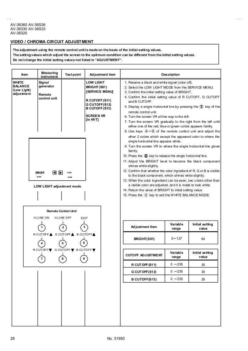
VIDEO / CHROMA CIRCUIT ADJUSTMENT
The adjustment using the remote control unit is made on the basis of the initial setting values.
The setting values which adjust the screen to the optimum condition can be different from the initial setting values.
Do no t change the initial setting values not listed in �ADJUSTMENT�.
Item Measuringinstrument
Test point Ad justment item Description
WHITEBALANCE(Low Light)adjustment
Signalgenerator
Remotecontrol unit
LOW LIGHTBRIGHT (S01)[SERVICE MENU]
R CUTOFF (S11)G CUTOFF(S12)B CUTOFF (S13)
SCREEN VR[In HVT]
1. Receive a black and white signal (color off).
2. Select the LOW LIGHT MODE from the SERVICE MENU. 3. Conf irm the initial sett ing value of BRIGHT.
4. Conf irm the initial sett ing value of R CUTOFF, G CUTOFFand B CUTOFF.
5. Display a single horizontal line by pressing the ①①①① key of the
remote control unit. 6. Turn the screen VR all the way to the left.
7. Turn the screen VR gradually to the right from the left unt ileither one of the red, blue or green colors appears faintly.
8. Use keys ④~⑨ of the remote control unit and adjust the
other 2 colors which except the appeared color to where thesingle horizontal line appears white.
9. Turn the screen VR to where the single horizontal line glowsfaintly.
10. Press the ②②②② key to release the single horizontal line.
11. Adjust the BRIGHT level to become the black componentshines white slight ly.
12. Conf irm that whether the color ingredient of R, G or B is visibleto the black component, which shines white slightly.
13. When the color ingredient can be seen, two colors other thana visible color are adjusted, and it is made to look white.
14. Return the value of BRIGHT to initial setting value.
15. Press the ③ key to exit the W HITE BALANCE MODE.
Ad justment itemVariablerange
Initial settingvalue
BRIGHT(S01) 0~127 64
CUTOFF ADJUSTMENTVariablerange
Initial settingvalue
R CUT OFF (S11) 0 ~255 30
G CUT OFF(S12) 0 ~255 30
B CUTOFF(S13) 0 ~255 30
BRIGHT***
***
***
LOW LIGHT adjustment mode
Remote Control Unit
H.LI NE ON
1 2 3
4 5 6
7 8 9
R CUTOFF
R CUTOFF
H.LI NE OFF
G CUTOFF
G CUTOFF
EXIT
B CUTOFF
B CUTOFF

No. 51950
AV-36360 AV-36S36AV-36330 AV-36S33
AV-36320
29
Item Measuringinstrument
Test point Ad justment item Description
WHITEBALANCE(High Lig ht)adjustment
Signalgenerator
Remotecontrol unit
HIGH LIGHT[SERVICE MENU]
R DRIVE(S14)B DRIVE(S15)
1. Receive the NTSC black and white s ignal (color of f).2. Select the HIGH LIGHT mode in the SERVICE MENU.
3. Conf irm the initial sett ing value of �G DRIVE� and �B DRIVE�.4. If they are dif fer, set the S14 and S15 to the correct initial
setting value in the 1 V/C(S) mode.
5. Adjust the screen color to white with the ④④④④, ⑥⑥⑥⑥ , ⑦⑦⑦⑦ and ⑨⑨⑨⑨
keys of the remote control unit.
SUB BRIGHTadjustment
Remotecontrol unit
S01 BRIGHT " White balance (low light and high light) adjustment should bedone.
1. Receive a NTSC broadcast.
2. Select the 1 V/C(S) mode from SERVICE MENU.3. Select S01 BRIGHT of the V/C(S) mode in SERVICE MENU.
4. Conf irm the initial sett ing value of the S01 BRIGHT.5. If the brightness is not the best with the initial sett ing value,
make f ine adjustment of the S01 BRIGHT until you get theoptimum brightness .
SUBCONT RASTadjustment
Remotecontrol unit
S02 PICT URE " Bright adjustment should be done.1. Receive a NTSC broadcast.
2. Select S02 PICTURE of the V/C(S) mode in SERVICE MENU.3. Conf irm the initial sett ing value of the S02 PICTURE.
4. If the contras t is not the bes t with the initial setting value, makefine adjustment of the S02 PICTURE until you get the opt imumcontrast.
DRIVE ADJUSTMENTVariable
rangeInitial setting
value
R DRIVE (S14) 0 ~ 127 64
B DRIVE (S15) 0 ~ 127 64
BRIGHT ADJUSTMENTVariable
rangeInitial setting
value
S01 BRIGHT 0 ~ 127 64
PICTUREADJUSTMENT
Variablerange
Initial settingvalue
S02 PICT URE 0 ~ 127 55
***
HIGH LIGHT adjustment
Remo te Cont rol Unit
H.LINE ON
1 2 3
4 5 6
7 8 9
R DRIVE
R DRIVE
H.LINE OFF EXIT
B DRIVE
B DRIVE

No. 51950
AV-36360 AV-36S36AV-36330 AV-36S33AV-36320
30
Item Measuring
instrumentTest point Ad justment part Description
[ Method of adjustment without measuring instrument ]SUB COLORadjustment
Remotecontrol unit
S03 COLOR[V/C(S) mode]
1. Receive the broadcast.2. Select the 1 V/C(S) mode from SERVICE MENU.
3. Select S03 COLOR of the V/C(S) mode.4. Conf irm the initial sett ing value of the S03 COLOR.
5. If the color is not the best with the Initial setting value, make fineadjustment of the S03 COLOR until you get the optimum color.
[ Method of adjustment using measuring instrument ]Signalgenerator
Oscilloscope
Remotecontrol unit
TP-BTP-E(#### )[CRT
SOCKETPWB]
S03 COLOR[V/C(S) mode]
1. Input the full color bar signal includes the 75% white.
2. Select the 9 RF AFC mode from SERVICE MENU.3. Turn the AFC item to off, and exit to SERVICE MAIN MENU.
4. Select the 1 V/C(S) mode from SERVICE MENU.5. Select S03 COLOR of the V/C(S) mode.
6. Conf irm the initial sett ing value of the S03 COLOR given above.7. Connect the osc illoscope between TP-B and TP-E.
8. Adjust S03 COLOR and bring the value of (A) in the illustration
to the voltage shown in the table bellow (voltage dif ference
between white and blue).9. Exit to the SERVICE MAIN MENU. And select the 9 RF AFC
mode.10. Turn the AFC item to on.
W Cy
YG
R
M gB
(A)
(―――― )
(++++ )
0V
Ad justment item Initial setting value
S03 COLOR 55
MODEL NAME Voltage difference [V]
AV-36360 /R
AV-36S36 /R
AV-36330 /RAV-36S33 /RAV-36320 /R
+20V
AV-36360 /M
AV-36S36 /M
AV-36330 /MAV-36S33 /MAV-36320 /M
+18V

No. 51950
AV-36360 AV-36S36AV-36330 AV-36S33
AV-36320
31
Item Measuring
instrumentTest point Ad justment part Description
[ Method of adjustment without measuring instrument ]SUB TINTadjustment
Remotecontrol unit
S04 TINT[V/C(S) mode]
1. Receive the broadcast.2. Select the 1 V/C(S) mode from SERVICE MENU.
3. Select S04 TINT of the V/C(S) mode.4. Conf irm the initial sett ing value of the S04 TINT.
5. If the tint is not the bes t with the Initial sett ing value, make fineadjustment of the S04 TINT until you get the optimum color.
[ Method of adjustment using measuring instrument ]Signalgenerator
Oscilloscope
Remotecontrol unit
TP-BTP-E(#### )[CRT
SOCKETPWB]
S04 TINT[V/C(S) mode]
1. Input the full color bar signal includes the 75% white.
2. Select the 9 RF AFC mode from SERVICE MENU.3. Turn the AFC item to off, and exit to SERVICE MAIN MENU.
4. Select the 1 V/C(S) mode from SERVICE MENU.5. Select S04 TINT of the V/C(S) mode.
6. Conf irm the initial sett ing value of the S04 TINT given above.7. Connect the osc illoscope between TP-B and TP-E.
8. Adjust S04 TINT and bring the value of (B) in the illustration to
the voltage shown in the table bellow (voltage dif ference
between white and magenta).9. Exit to the SERVICE MAIN MENU. And select the 9 RF AFC
mode.10. Turn the AFC item to on.
W Cy
YG
R
M gB
(B)
(――――)
(++++)
0V
Ad justment item Initial setting value
S04 TINT 64
MODEL NAME Voltage difference [V]
AV-36360 /M
AV-36S36 /M
AV-36330 /MAV-36S33 /MAV-36320 /M
AV-36360 /R
AV-36S36 /R
AV-36330 /RAV-36S33 /RAV-36320 /R
+6V
+2V

No. 51950
AV-36360 AV-36S36AV-36330 AV-36S33AV-36320
32
PIP CIRCUIT ADJUSTMENT [Only for AV-36360, AV-36S36]
ItemMeasuring
instrumentTest point Ad justment part Description
PIP WHITEBALANCEadjustment(HIGH LIGHT)
Signalgenerator
Remotecontrol unit
PIP08 R DRIVEPIP10 B DRIVE[PIP(PIP) mode]
1. Receive the black and white signal (color of f).
2. Select the 5 PIP mode from SERVICE MENU.3. Select the PIP08 R DRIVE, PIP10 B DRIVE of the PIP mode.
4. Conf irm the initial sett ing values of PIP08 and PIP10.5. Adjust the PIP08 R DRIVE, PIP10 B DRIVE unt il the screen
becomes white.
PIP DISPLAYPOSITIONadjustment
Signalgenerator
Remotecontrol unit
PIP11 L POSIPIP12 R POSIPIP13 UPR POSIPIP14 LWR POSI[PIP(PIP) mode]
1. Receive the black and white signal (color of f).2. Select the 5 PIP mode from SERVICE MENU.
3. Select the PIP11 L POSI of the PIP mode.
4. Conf irm the initial setting value of the PIP11 L POSI~PIP14
LWR POSI.
5. Adjust the PIP11~PIP14 to become the each PIP screen
outside edges positioned about the lef t mentioned values fromscreen edge.
PIP S CREEN
80%
80%92%V SIZE adjustment value
92%H SIZE adjustment value
80%
80%
Ad justment item Initial setting value
PIP11 L POSI 22
PIP12 R POSI 15
PIP13 UPR POSI 12
PIP14 LWR POSI 11
Ad justment item Initial setting value
PIP08 R DRIVE 63
PIP10 B DRIVE 65
Ad justment position Ad justment value[Screen size]
UPPER WIDTH 80%
LOWER WIDTH 80%
LEFT WIDT H 80%
RIGHT WIDTH 80%

No. 51950
AV-36360 AV-36S36AV-36330 AV-36S33
AV-36320
33
MTS CIRCUIT ADJUSTMENT
ItemMeasuring
instrumentTest point Ad justment part Description
MTS INPUTLEVELcheck
Remotecontrol unit
A01 IN LEVEL[SOUND(A) mode]
1. Select the A01 IN LEVEL of the SOUND mode.
2. Verify that the A01 IN LEVEL is set at its initial sett ing value.
MTSSEPARATIONadjustment
TV audiomultiplexsignalgenerator
Oscilloscope
Remotecontrol unit
R OUTL OUT
[AUDIO OUT]
A02 LOW SEPA03 HI SEP
1. Input the stereo L s ignal (300Hz) from the TV audio multiplex
signal generator to the antenna terminal.2. Connect an oscilloscope to R OUT pin of the AUDIO OUT, and
display one cycle port ion of the 300Hz signal.3. Select the A02 LOW SEP of the SOUND MODE.
4. Conf irm the initial sett ing value of the A02 LOW SEP.5. Adjust the A02 LOW SEP so that the stroke element of the
300Hz signal will become minimum.6. Change the connec tion of the oscilloscope to L OUT pin of the
AUDIO OUT, and enlarge the voltage axis.7. Change the signal to 3kHz, and similarly adjust the A03 HI
SEP.
L-Channelsignal waveform
R-Channelcrosstalk portion
Minimum
1 cycle
Ad justment item Initial setting value
A01 IN LEVEL 10
Ad justment item Initial setting value
A02 LOW SEP 32
A03 HIGH SEP 32

No. 51950
AV-36360 AV-36S36AV-36330 AV-36S33AV-36320
34
HOW TO CHECK THE HIGH VOLTAGE HOLD DOWN CIRCUIT 1. HIGH VOLT AGE HOLD DOWN CIRCUIT
After repairing the high voltage hold down c ircuit .
This circuit shall be checked to operate correct ly.
2. CHECKING OF THE HIGH VOLTAGE HOLD DOWN CIRCUIT
(1) Turn the power switch on.
(2) As shown in figure, set the res istor (between【S1】connector【2】and【3】).
(3) Make sure that the screen pic ture disappears.
(4) Temporarily unplug the power plug.
(5) Remove the resistor (between【S1】connector【2】and【3】).
(6) Again plug the power plug, make sure that the normal picture is displayed on the screen.
3 2 1 S1 CONNECTOR
RESISTOR
RESISTOR
All model : 22.8kΩ±Ω±Ω±Ω±0.5% 1/4W