Embed Size (px)
Citation preview
7/28/2019 Bariera SOOMER
http://slidepdf.com/reader/full/bariera-soomer 1/42
ASB6010-7604v001-312010-0-OCE_GB
tt Origia istaatio ad operatig maua 1 - 42
ASB 6010 Attach guarantee
sticker here!
7/28/2019 Bariera SOOMER
http://slidepdf.com/reader/full/bariera-soomer 2/42– 2t
Copyrights ad proprietary rights
The manufacturer retains the copyright for this manual. No part of these
instructions may be reproduced in any form without the written permission of SOMMER Antriebs- und Funktechnik GmbH or processed, copied, or distributed
using electronic systems.
Violations of the specications above will lead to damage claims.
All brands mentioned in these instructions are the property of their respective
manufacturer and hereby recognized as such.
Cotact data
If you need customer service, spare parts, or accessories, please contact your
specialist dealer or SOMMER Antriebs- und Funktechnik GmbH directly.
SOMMER Antriebs- und Funktechnik GmbH
Hans-Böckler-Str. 21-27
D-73230 Kirchheim/Teck
www.sommer-torantriebe.de
0049 / 7021 / 8001-400
Feedback regardig this maua
We have tried to make the installation and operating instructions as easy as
possible to follow. If you have any suggestions as to how we could improve them
or if you think more information is needed, please send your suggestions to us:
0049 / 7021 / 8001-403
Iformatio regardig the barrier
Serial No.: Specied on the title page of this manual.
Year of construction: From 02/2010
Iformatio regardig the maua
Version of the manual V. 2.5/07/2010
The language of the original installation and operating manual is German.
All other language versions are translations of the original installation andoperating manual and thus labeled as such.
7/28/2019 Bariera SOOMER
http://slidepdf.com/reader/full/bariera-soomer 3/42– 3t
Tabe of cotetsUser iformatio ............................................................ 4
Storage and circulation of the manual.............................................. 4
Description of the product type ........................................................ 4
Target group of the manual .............................................................. 4
Other applicable documents ............................................................ 4
Explanation of symbols .................................................................... 4
Information regarding the depiction of text ....................................... 4
Safety iformatio ......................................................... 5
Warranty ........................................................................................... 5
Intended use ....................................................................................5
Improper use ....................................................................................5
Qualication of the personnel ........................................................... 5
Operator responsibilities ..................................................................6
Safety labeling on the barrier ........................................................... 6
Personal safety equipment............................................................... 6
Spare parts and accessories............................................................ 6
Product descriptio....................................................... 7
Scope of supply................................................................................ 7
Dimensions ...................................................................................... 8Technical data .................................................................................. 8
Type plate ......................................................................................... 8
Trasport/uoadig/storage ........................................ 9
Transport .......................................................................................... 9
Unloading and in-house transport .................................................... 9
Storage............................................................................................. 9
Istaatio preparatios ............................................. 10
Installation drawing .........................................................................11
Creation of barrier foundation with supply connections ..................11
Creating the foundation of the support post ....................................11
Stationary command initiators ........................................................ 12Safety measures ............................................................................ 12
Pedestrian trafc ............................................................................ 12
Tools required ................................................................................. 12
Istaatio.................................................................... 13
Safety information for installation ................................................... 13
Checking the scope of supply ........................................................ 13
Installation of the barrier housing ................................................... 13
Adapting the length of the boom .................................................... 14
Installation of the boom .................................................................. 14
Installation of the support post ....................................................... 14
Aligning the position of the barrier .................................................. 14
Installation of accessories .............................................................. 15
Connection to the power mains...................................................... 17
Commissioig............................................................ 18
Safety information for installation ................................................... 18
Check of the cable of the direct connector ..................................... 18
Adjustment of the spring unit.......................................................... 18
Checking the direction of running................................................... 18
Check of the path of the barrier ...................................................... 19
Performing a control system reset and relearning the force values...20
Adjusting the force tolerance.......................................................... 20
Optioa had-hed trasmitter .................................. 21
Safety information for the remote control ....................................... 21
Deleting the memory of the radio receiver ..................................... 21
Programming the hand-held remote control................................... 21
Deleting the hand-held transmitter from the radio receiver ............ 21
Deleting a channel from the radio receiver .................................... 21
Loss of a hand-held transmitter ...................................................... 21
Operatio ad cotro ................................................. 22
Safety information on operation ..................................................... 22
Operation with automatic closing function...................................... 22
Single channel operation................................................................ 23
Emergency release ........................................................................ 23
Cotro .......................................................................... 24
Safety information .......................................................................... 24
Overview of the control system ...................................................... 24
Mains connection ........................................................................... 25
Functions of the control system ..................................................... 25
DIP switches .................................................................................. 26
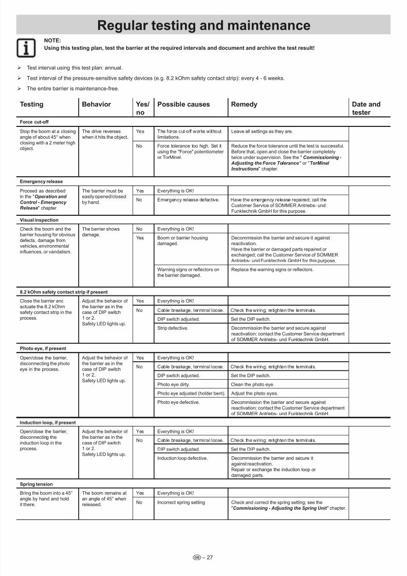
Reguar testig ad maiteace .............................. 27
Troubeshootig .......................................................... 28
Change the fuse. ............................................................................ 28
Changing the spring ....................................................................... 28
Troubeshootig .......................................................... 29
Fault - cause - elimination .............................................................. 29
Disassemby ad disposa.......................................... 31Safety information for disassembly ................................................ 31
Storage after disassembly.............................................................. 31
Description of the disassembly work .............................................. 31
Disposal ......................................................................................... 32
Appedix ...................................................................... 33
EC declaration of conformity .......................................................... 33
Entrance and exit scenarios ........................................................... 34
Drill template .................................................................................. 38
Barrier handover report .................................................................. 40
Brief instructions ............................................................................. 42

7/28/2019 Bariera SOOMER
http://slidepdf.com/reader/full/bariera-soomer 4/42– 4t
Storage ad circuatio of
the mauaThis manual must always be available at the site of installation and use of
the barrier.
The operator must inform the personnel about the storage location of thismanual and its supplementary manuals.
If the manual has become unreadable due to constant use, the operator must obtain a replacement from the manufacturer. To reorder the manual,contact the Customer Service department.
During the transfer or resale of the barrier to third parties, the following
document must be passed on to the new owner:
• This manual
• The retrotting and repair work documents
• Proof of regular testing
• Other applicable documents; see the "User Information - Other
Applicable Documents" chapter.
Descriptio of the product typeThe ASB 6010 barrier has been constructed according to state-of-the-art
technology and recognized technical regulations and is subject to the ECMachinery Directive (2006/42/EC). A Declaration of Conformity has been
included in this manual.
This manual describes an industrially, commercially, and privately usable,
powered barrier for vehicle trafc. The barrier is used to block and open
entrances and exits from parking lots and other drives.
The ASB 6010 barrier is available in both right-closing and left-closing
designs. A conversion is ot possible.
Optionally available accessories are also described. The actual scope of
supply may deviate.
Target group of the mauaThe manual must be read and observed by everyone assigned with one of
the following tasks:
• In-house transport
• Unpacking and installation
• Commissioning
• Adjustment
• Troubleshooting
• Testing
• Decommissioning
• Disassembly
• Storage
• Disposal
Other appicabe documetsIn addition to this manual, observe the following (technical) documents/
regulations:
• National regulations regarding accident prevention
• National regulations regarding environmental protection
• Information regarding supervisory and reporting responsibilities, as well
as company organization
• Recognized technical regulations for safe work
Expaatio of symbosThe following symbols and signal words are used in this manual:
DAnGER
Desigates a immediate dager that eads to death or
extremey severe ijuries.
WARnInG
Desigate a possiby dagerous situatio ead ca ead
to death, extremey severe ijuries, or damage to the barrier
ad eviromet.
nOTE:
Desigates more iformatio ad usefu tips.
Refers to a part or machie compoet i a picture.
Warig symbos
If the source of danger can be specied more precisely, the following
symbols are used together with the abovementioned signal words:
DAnGER DUE TO ElECTRIC CURREnT!
In case of contact with live parts, current can ow through
a body, possiby eadig to eectric shock, burs, or death.
DAnGER OF TIPPInG!
This symbo is used to abe a dager of tippig durig the
trasport ad istaatio of the barrier.
DAnGER DUE TO ClOSInG BARRIER!
The o-observace of the rues of behavior ead toa dagerous situatio that ca ead to severe ijuries.
Iformatio regardig the
depictio of text ¾ Stands for general safety instructions that must be observed!
Stands for directions for an action with one or two instructions.
1. Stands for directions for an action with three or more instructions.
• Stands for lists of the action.
⇒ Stands for the results of the action.
Lists without a mandatory order are shown as a list with bullets (Level 1)
and en-dashes (Level 2):
• List 1
– Point A
– Point B
• List 2
References to chapters and other documents are bolded, italicized, and
placed in "quotation marks."
User iformatio

7/28/2019 Bariera SOOMER
http://slidepdf.com/reader/full/bariera-soomer 5/42– 5t
WarratyThe warranty complies with statutory requirements. The contact person for warranties is the dealer.
The warranty is only valid in the country in which the barrier was purchased.
Batteries, fuses and bulbs are excluded from the warranty.
Iteded useOperate the barrier only in a perfect, trafc-safe state in a safety-conscious
and risk-conscious manner.
The industrially, commercially, and privately usable ASB 6010 barrier is
suited for the following applications:
• To block and open the entrances and exists of parking lots and other
drives to which vehicles of all type have access
• Use with a 1.5 to 6 meter long boom (length of 5 meters in case of
oating support)
• Use of a maximum of 13 cycles an hour
• Use with the required safety clearances to the surroundings
• Use with suitable safety devices and command initiators oriented onthe expected vehicle trafc
• Use up to a maximum wind strength of 8 on the Beaufort scale
(stormy wind).
Improper useEvery use not listed in the " Intended Use" chapter is considered to be
improper. The operator of the barrier is solely responsible for resultingdamage. This also applies to unauthorized changes, modications, and
programming of the barrier and its parts.
In particular, the following is not permitted:
• Use by pedestrians and cyclists (bicycles)
• Use at toll booths
• Use in parking garages
• Use with defective parts
• Use in enclosed spaces
• Use in explosive atmospheres or in environments with hazardous,
ammable gases
• Installation of the barrier without a foundation or with a foundation thatdoes not meet the requirements listed in the "Installation Preparations
- Creation of Barrier Foundation with Supply Connections" chapter
• Use on foundations with an incline or slope
• Use of spare parts and accessories that have ot been tested and
released by SOMMER Antriebs- und Funktechnik GmbH
• Modication of the barrier or individual parts without the permission of
SOMMER Antriebs- und Funktechnik GmbH
• Misuse of the barrier or individual parts for a similar area of application
Qualication of the personnelPeople under the inuence of drugs, alcohol, or medications that can
inuence their ability to react may not transport, install, operation, adjust,
or disassemble the barrier.
Operator
The operator owns the barrier or has rented it.
In addition to the contractually regulation transfer of responsibilities to the
operator, it is also responsible for the intended use of the barrier.
The operator is responsible for making sure its entire personnel fullls all
necessary physical and mental requirements for the tasks assigned to them.
Qualied transport personnel
The barrier is transported to the operator by a specialist dealer or by
a haulage company commissioned by the specialist dealer.
Transport may not be performed by the operating personnel or by the
operator. In-house transport is excepted here.
Qualied personnel for the foundation
The foundation of the barrier may be laid only by a trained expert. For thispurpose, a required proof of static stability must be provided according to
the local building code.
If necessary, consult a structural engineer.
Qualied personnel for installation,
commissioig, ad disassemby
The installation, commissioning, and disassembly of the barrier may only
be performed by a trained expert.
The personnel must be familiar with the local accident prevention regulations.
Minors or trainees may perform this work only with the supervision of an
experienced expert and with express permission of the operator.
Eectricias
Work on the electrical system and live parts may be performed only by
a trained electrician.
Work on the electrical system or live parts may not be performed by
installation, commissioning, and disassembly personnel or the operator.
Qualied operating personnel
The qualied operating personnel are assigned the following responsibilities
and tasks:
• Setting of the operating mode
• Emergency release of the barrier
• Elimination of malfunctions or the initiation of measures to eliminatemalfunctions
• Testing of the barrier according to the intervals specied in the test plan
This person must be named by the operator and have taken part in training
for the operation of the barrier provided by the operator.
Minors or trainees may perform this work only with the supervision of an
experienced expert and with express permission of the operator.
Safety iformatio
7/28/2019 Bariera SOOMER
http://slidepdf.com/reader/full/bariera-soomer 6/42
Safety iformatio
t – 6
Users
The barrier may be used by all persons who have reached the age of 18.
Minors may use the barrier only when accompanied by someone who is
of age.
The qualied operating personnel are assigned the following responsibilities
and tasks:
• Opening and closing the barrier using the command initiators• Use of the barrier with vehicles guided (control) by the users
Operator resposibiitiesThe operator of the barrier remains responsible for its use at all times
unless otherwise agreed. This also applies when the barriers are used by
third parties.
We would like to point out expressly that the ASB 6010 barrier may onlybe used for vehicle trafc. People may not use the barrier. The operator
must use suitable measures to guarantee a strict separation of vehicle and
pedestrian trafc. Structural separations like pedestrian paths next to the
lane must be supplemented with warnings and corresponding signs.
Using suitable measures, the opening and closing movements must be
observed and monitored. The operation of the barrier installation without
safety devices, visual supervision, or monitoring is not permitted.
In addition, the operator of the barrier must do the following:
• Assign the various tasks at the barrier to qualied, suitable,
authorized personnel
• Provably train the operating personnel in the proper operation of the
barrier and the effect of all safety devices. The training or instruction of
the personnel must be conrmed in writing!
• Damage and faulty parts must be eliminated by suitable qualied
personnel immediately.
• Commission experts with tests at regular intervals and keep a record of
these tests
• Document retrotting work
• Make sure that the barrier is operated only in a technically perfect
condition
• Equip the personnel with suitable protective work clothes
• Installation of signal boards, notices, or structures (railings) so that
pedestrians are sufciently warned and do not walk through the barrier
installation
• Design the entrance widths for vehicles in such a way that wider,
longer, and high vehicles can enter comfortably without damaging
the installation.
nOTE:
See the "Istaatio Preparatios" chapter. The ecessary
preparatios ad resposibiities are isted there.
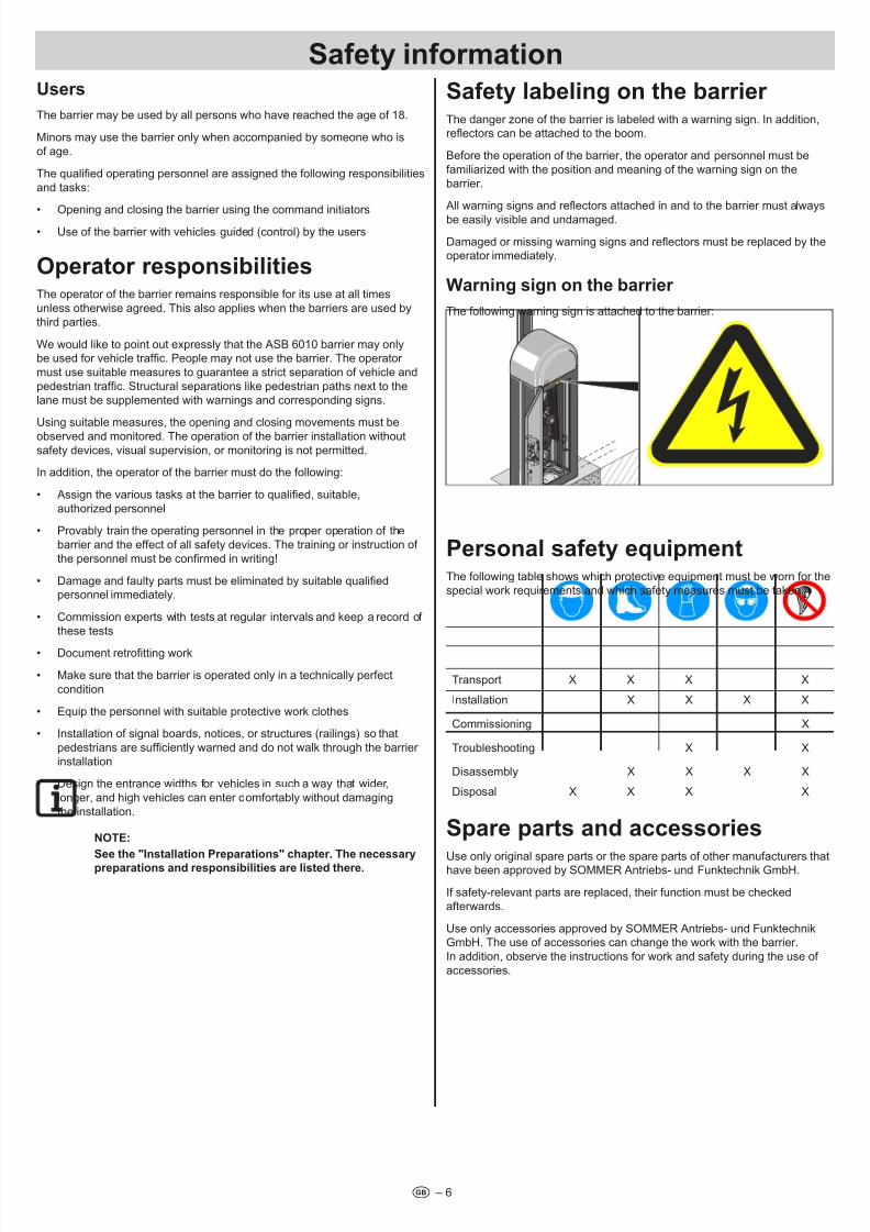
Safety abeig o the barrier The danger zone of the barrier is labeled with a warning sign. In addition,reectors can be attached to the boom.
Before the operation of the barrier, the operator and personnel must be
familiarized with the position and meaning of the warning sign on the
barrier.
All warning signs and reectors attached in and to the barrier must always
be easily visible and undamaged.
Damaged or missing warning signs and reectors must be replaced by the
operator immediately.
Warig sig o the barrier
The following warning sign is attached to the barrier:
Persoa safety equipmetThe following table shows which protective equipment must be worn for the
special work requirements and which safety measures must be taken.
Transport X X X X
Installation X X X X
Commissioning X
Troubleshooting X X
Disassembly X X X X
Disposal X X X X
Spare parts ad accessoriesUse only original spare parts or the spare parts of other manufacturers thathave been approved by SOMMER Antriebs- und Funktechnik GmbH.
If safety-relevant parts are replaced, their function must be checked
afterwards.
Use only accessories approved by SOMMER Antriebs- und Funktechnik
GmbH. The use of accessories can change the work with the barrier.
In addition, observe the instructions for work and safety during the use of
accessories.
7/28/2019 Bariera SOOMER
http://slidepdf.com/reader/full/bariera-soomer 7/42– 7t
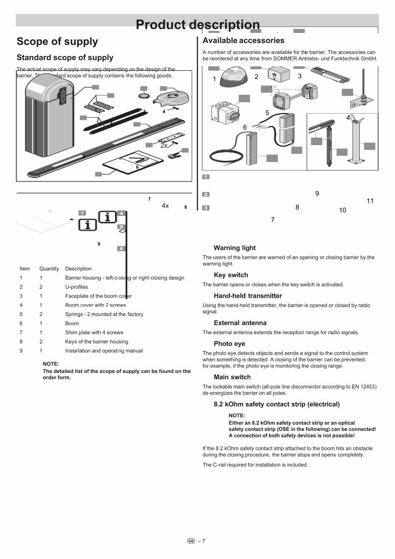
Scope of suppy
Stadard scope of suppy
The actual scope of supply may vary depending on the design of the
barrier. The standard scope of supply contains the following goods:
B e d i e n u n g s a n l e i t u n
g
1
S O M M E R
T O R A N T R I E B E
M a d
e
i n
G e
r m
a n
y
D
D
3
6
4
9
1
5
8
7
4x
2
2x
Item Quantity Description
1 1 Barrier housing - left-closing or right-closing design
2 2 U-proles
3 1 Faceplate of the boom cover
4 1 Boom cover with 2 screws
5 2 Springs - 2 mounted at the factory
6 1 Boom
7 1 Shim plate with 4 screws
8 2 Keys of the barrier housing
9 1 Installation and operating manual
nOTE:
The detaied ist of the scope of suppy ca be foud o the
order form.
Avaiabe accessories
A number of accessories are available for the barrier. The accessories can
be reordered at any time from SOMMER Antriebs- und Funktechnik GmbH.
SOMMER
TOR ANTRIEBE
2
01
O
1 2
6
7
10
11
8
9
3
45
Warig ight
The users of the barrier are warned of an opening or closing barrier by the
warning light.
Key switch
The barrier opens or closes when the key switch is activated.
Had-hed trasmitter
Using the hand-held transmitter, the barrier is opened or closed by radiosignal.
Extera atea
The external antenna extends the reception range for radio signals.
Photo eye
The photo eye detects objects and sends a signal to the control system
when something is detected. A closing of the barrier can be prevented,
for example, if the photo eye is monitoring the closing range.
Mai switch
The lockable main switch (all-pole line disconnector according to EN 12453)
de-energizes the barrier on all poles.
8.2 kOhm safety cotact strip (eectrica)
nOTE:
Either a 8.2 kOhm safety cotact strip or a optical
safety cotact strip (OSE i the followig) ca be coected!
A coectio of both safety devices is ot possible!
If the 8.2 kOhm safety contact strip attached to the boom hits an obstacle
during the closing procedure, the barrier stops and opens completely.
The C-rail required for installation is included.
Product descriptio
7/28/2019 Bariera SOOMER
http://slidepdf.com/reader/full/bariera-soomer 8/42
Product descriptio
t – 8
Optica safety cotact strip - OSE system
nOTE:
Either a 8.2 kOhm safety cotact strip or a optical
safety cotact strip (OSE i the followig) ca be coected!
A coectio of both safety devices is ot possible!
If the 8.2 kOhm safety contact strip attached to the boom hits an obstacle
during the closing procedure, the barrier stops and opens completely.
The C-rail required for installation must be purchased separately.
Reectors
Reectors attached to the boom increase the visibility of the boom in the dark.
Foatig support (up to a maximum boom egth of
5 meters)
In case of a boom length of 3 to 5 meters, either a oating support or
a support post must be installed. In case of a boom length of more than
5 meters, a support post must be installed.
Support post
In case of a boom length of 3 to 5 meters, either a oating support or
a support post must be installed. In case of a boom length of more than
5 meters, a support post must be installed.
loop evauatio
If induction loops are present on-site for the opening or closing of the barrier,their signals can be processed using loop evaluation.
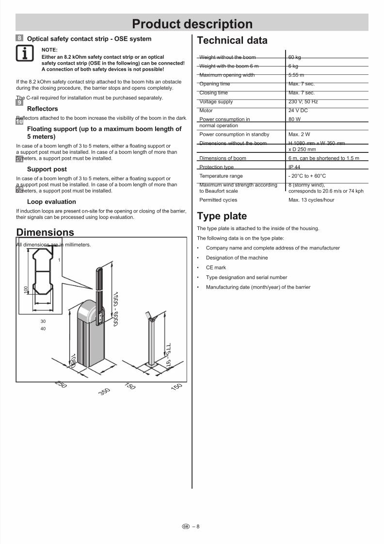
Dimesios All dimensions are in millimeters.
7 7 5 - 9 7 5
1 5 0
1 5 0
1 5 0 0 - 6 0 0 0
1 0 8 0
3 5 0
2 5 0
1 0 0
40
30
1
Techica data
Weight without the boom 60 kg
Weight with the boom 6 m 6 kg
Maximum opening width 5.55 m
Opening time Max. 7 sec.
Closing time Max. 7 sec.Voltage supply 230 V; 50 Hz
Motor 24 V DC
Power consumption in
normal operation
80 W
Power consumption in standby Max. 2 W
Dimensions without the boom H 1080 mm x W 350 mmx D 250 mm
Dimensions of boom 6 m, can be shortened to 1.5 m
Protection type IP 44
Temperature range - 20°C to + 60°C
Maximum wind strength according
to Beaufort scale
8 (stormy wind),
corresponds to 20.6 m/s or 74 kph
Permitted cycles Max. 13 cycles/hour
Type pateThe type plate is attached to the inside of the housing.
The following data is on the type plate:
• Company name and complete address of the manufacturer
• Designation of the machine
• CE mark
• Type designation and serial number
• Manufacturing date (month/year) of the barrier
7/28/2019 Bariera SOOMER
http://slidepdf.com/reader/full/bariera-soomer 9/42– 9t
TrasportThe barrier is transported to the operator by a specialist dealer or bya haulage company commissioned by the specialist dealer.
After the contractually regulated handover of all responsibility to the
operator, the operator must make sure that the barrier is safely and properly
transported during transport.
The following information regarding transport absolutely must be observed:
¾ Do not stack the packaging units on top of each other.
¾ Transport the packaging units in the position specied on the packaging.
¾ Even during transport, observe the ambient conditions (temperature,
humidity, etc.) required by the manufacturer.
¾ Always make sure that the barrier is transported without impacts and jolts.
¾ Always secure the loads to be transported against falling, tipping over,
and damage.
Uoadig ad i-house trasport
WARnInG
Durig this work, dagers may arise, for exampe, due toueve surfaces, sharp edges, or the use of operatig
materias ad adjuvats.
Body parts may be ijured.
¾ Wear suited, closely tting protective work clothes
(safety hemet, safety shoes, ad safety goves at
miimum). Do ot wear og hair oosey.
DAnGER
Faig oad!
Durig uoadig, the oad may fa ad cause severe or
deady ijuries.
¾ Use liftig equipmet desiged for the weight of the load.
¾ never wak uder suspeded oads.
Check packaging units for externally recognizable transport damageor other damager. In case of damage, have i t conrmed by the haulage
company and inform SOMMER Antriebs- und Funktechnik GmbH
immediately in writing.
After unloading, store the barrier until setup. For this purpose, the operator of the barrier might have to transport the barrier for the place of unloading
to the storage location.
In the process, observe the following information regarding unloading and
intermediate transport:
¾ For unloading and in-house transport, at least two people are required.
¾ Only use suitable, tested, and standardized lifting equipment (fork lifttruck, mobile crane, overhead crane) and means of suspension
(slings, lifting belts, sling ropes, chains).
¾ When selecting the lifting equipment and means of suspension,
always take the maximum load-bearing capacities into consideration.
¾ Always make sure that the barrier is unloaded and transported withoutimpacts and jolts.
¾ Do not stack the packaging units on top of each other.
¾ After unloading, do ot remove the packaging materials or transport
safety devices.
Storage
WARnInG
The drive ad other subassembies of the barrier may be
damaged by icorrect storage.
Irreparabe damage to the barrier may be the resut.
¾ Observe the following storage conditions at rst
deivery ad itermediate storage!
The packaging units are packed in a plastic lm for transport that protects
them against environmental inuences.
¾ Do not remove or damage this plastic lm. If necessary, additionally
cover the subassemblies.
¾ Store the packaging units in enclosed, dry rooms so that they areprotected against moisture and UV radiation.
¾ Store the packaging units at a storage temperature from –20°C to +60°C.
¾ Store the packaging units in the position specied on the packaging.
¾ Do not stack the packaging units on top of each other.
¾ Leave room for unhindered passage.
Trasport/uoadig/storage
7/28/2019 Bariera SOOMER
http://slidepdf.com/reader/full/bariera-soomer 10/42– 10t
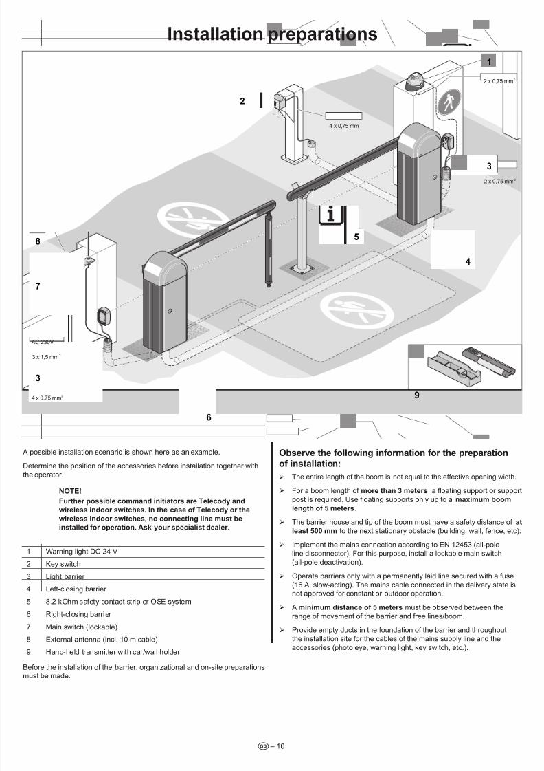
A possible installation scenario is shown here as an example.
Determine the position of the accessories before installation together with
the operator.
nOTE!
Further possibe commad iitiators are Teecody ad
wireess idoor switches. I the case of Teecody or the
wireess idoor switches, o coectig ie must be
istaed for operatio. Ask your speciaist deaer.
1 Warning light DC 24 V
2 Key switch
3 Light barrier
4 Left-closing barrier
5 8.2 kOhm safety contact strip or OSE system
6 Right-closing barrier
7 Main switch (lockable)
8 External antenna (incl. 10 m cable)
9 Hand-held transmitter with car/wall holder
Before the installation of the barrier, organizational and on-site preparations
must be made.
Observe the foowig iformatio for the preparatio
of istaatio:
¾ The entire length of the boom is not equal to the effective opening width.
¾ For a boom length of more tha 3 meters, a oating support or support
post is required. Use oating supports only up to a maximum boom
egth of 5 meters.
¾ The barrier house and tip of the boom must have a safety distance of at
east 500 mm to the next stationary obstacle (building, wall, fence, etc).
¾ Implement the mains connection according to EN 12453 (all-pole
line disconnector). For this purpose, install a lockable main switch
(all-pole deactivation).
¾ Operate barriers only with a permanently laid line secured with a fuse
(16 A, slow-acting). The mains cable connected in the delivery state is
not approved for constant or outdoor operation.
¾ A miimum distace of 5 meters must be observed between the
range of movement of the barrier and free lines/boom.
¾ Provide empty ducts in the foundation of the barrier and throughout
the installation site for the cables of the mains supply line and the
accessories (photo eye, warning light, key switch, etc.).
Istaatio preparatios
O
SOMMER
TOR ANTRIEBE
2
01
9
1
2 x 0,75 mm2
4 x 0,75 mm
2 x 0,75 mm2
2
33
8
7
3 x 1,5 mm2
AC 230V
3
4 x 0,75 mm2
6
4
5
7/28/2019 Bariera SOOMER
http://slidepdf.com/reader/full/bariera-soomer 11/42
Istaatio preparatios
t – 11
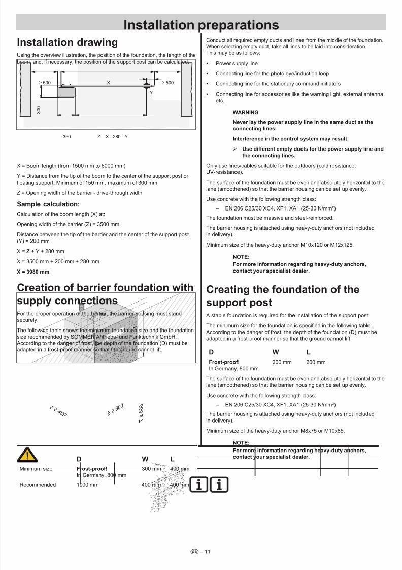
Istaatio drawigUsing the overview illustration, the position of the foundation, the length of the
boom, and, if necessary, the position of the support post can be calculated.
Y
≥ 500
3 0 0
≥ 500X
350 Z = X - 280 - Y
X = Boom length (from 1500 mm to 6000 mm)
Y = Distance from the tip of the boom to the center of the support post or
oating support. Minimum of 150 mm, maximum of 300 mm
Z = Opening width of the barrier - drive-through width
Sampe cacuatio:
Calculation of the boom length (X) at:
Opening width of the barrier (Z) = 3500 mm
Distance between the tip of the barrier and the center of the support post(Y) = 200 mm
X = Z + Y + 280 mm
X = 3500 mm + 200 mm + 280 mm
X = 3980 mm
Creatio of barrier foudatio with
suppy coectiosFor the proper operation of the barrier, the barrier housing must standsecurely.
The following table shows the minimum foundation size and the foundation
size recommended by SOMMER Antriebs- und Funktechnik GmbH. According to the danger of frost, the depth of the foundation (D) must be
adapted in a frost-proof manner so that the ground cannot lift.
T≥800
B ≥ 30
0L ≥ 4 0 0
D W l
Minimum size Frost-proof!
In Germany, 800 mm
300 mm 400 mm
Recommended 1000 mm 400 mm 400 mm
Conduct all required empty ducts and lines from the middle of the foundation.
When selecting empty duct, take all lines to be laid into consideration.
This may be as follows:
• Power supply line
• Connecting line for the photo eye/induction loop
• Connecting line for the stationary command initiators
• Connecting line for accessories like the warning light, external antenna,
etc.
WARnInG
never ay the power suppy ie i the same duct as the
coectig ies.
Iterferece i the cotro system may resut.
¾ Use differet empty ducts for the power suppy ie ad
the coectig ies.
Only use lines/cables suitable for the outdoors (cold resistance,
UV-resistance).
The surface of the foundation must be even and absolutely horizontal to the
lane (smoothened) so that the barrier housing can be set up evenly.
Use concrete with the following strength class:
– EN 206 C25/30 XC4, XF1, XA1 (25-30 N/mm²)
The foundation must be massive and steel-reinforced.
The barrier housing is attached using heavy-duty anchors (not included
in delivery).
Minimum size of the heavy-duty anchor M10x120 or M12x125.
nOTE:
For more iformatio regardig heavy-duty achors,
cotact your speciaist deaer.
Creatig the foudatio of the
support post A stable foundation is required for the installation of the support post.
The minimum size for the foundation is specied in the following table.
According to the danger of frost, the depth of the foundation (D) must be
adapted in a frost-proof manner so that the ground cannot lift.
D W l
Frost-proof!
In Germany, 800 mm
200 mm 200 mm
The surface of the foundation must be even and absolutely horizontal to the
lane (smoothened) so that the barrier housing can be set up evenly.
Use concrete with the following strength class:
– EN 206 C25/30 XC4, XF1, XA1 (25-30 N/mm²)
The barrier housing is attached using heavy-duty anchors (not included
in delivery).
Minimum size of the heavy-duty anchor M8x75 or M10x85.
nOTE:
For more iformatio regardig heavy-duty achors,
cotact your speciaist deaer.
7/28/2019 Bariera SOOMER
http://slidepdf.com/reader/full/bariera-soomer 12/42
Istaatio preparatios
t – 12
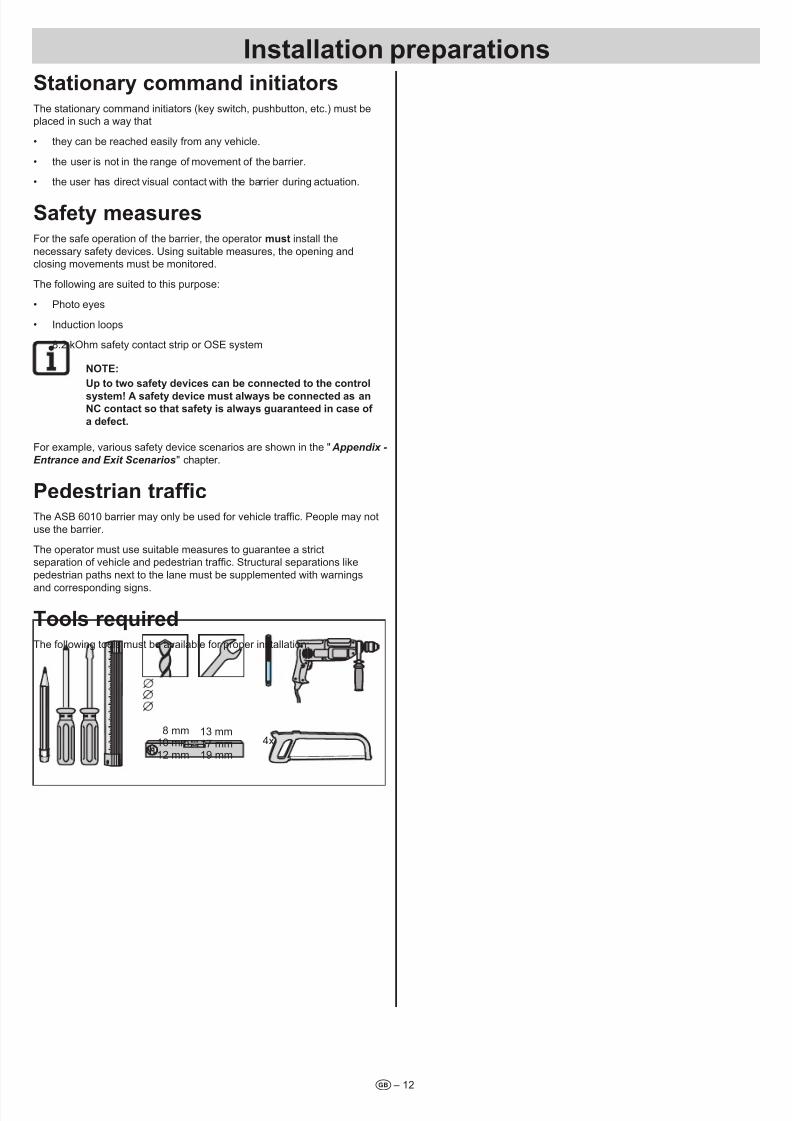
Statioary commad iitiatorsThe stationary command initiators (key switch, pushbutton, etc.) must be
placed in such a way that
• they can be reached easily from any vehicle.
• the user is not in the range of movement of the barrier.
• the user has direct visual contact with the barrier during actuation.
Safety measuresFor the safe operation of the barrier, the operator must install the
necessary safety devices. Using suitable measures, the opening and
closing movements must be monitored.
The following are suited to this purpose:
• Photo eyes
• Induction loops
• 8.2 kOhm safety contact strip or OSE system
nOTE:
Up to two safety devices ca be coected to the cotro
system! A safety device must aways be coected as anC cotact so that safety is aways guarateed i case of
a defect.
For example, various safety device scenarios are shown in the " Appendix -
Entrance and Exit Scenarios" chapter.
Pedestrian trafcThe ASB 6010 barrier may only be used for vehicle trafc. People may not
use the barrier.
The operator must use suitable measures to guarantee a strictseparation of vehicle and pedestrian trafc. Structural separations like
pedestrian paths next to the lane must be supplemented with warnings
and corresponding signs.
Toos requiredThe following tools must be available for proper installation:
13 mm
17 mm
19 mm
10 mm
12 mm
8 mm
4x
7/28/2019 Bariera SOOMER
http://slidepdf.com/reader/full/bariera-soomer 13/42– 13t
Safety iformatio for istaatio ¾ Perform installation only up to a maximum wind strength of 3 on the
Beaufort scale (light wind).
¾ At east two peope are required for the entire installation.
¾ For installation work performed above body height, used suitable,
tested, and stable climbing aids. Never use the barrier or parts of
the barrier as climbing aids.
¾ Check all screws and terminals in and on the barrier for a rm seat
and tighten them, if necessary.
¾ The installation of the barrier and all work on the electric system
may only be performed by the personnel described in the "Safety
Information - Qualication of the Personnel " chapter.
DAnGER OF TIPPInG!
The barrier may tip durig istallatio ad i-house trasport.
Peope ca be ijured ad the barrier ca be damaged.
¾ Trasport ad istaatio may be performed oy with
two peope ad suitabe trasport equipmet.
Checkig the scope of suppyRemove the barrier and all accessories from the packaging at the
installation site. No sharp objects may be used to open the packaging
since parts could otherwise be damaged.
Check the delivery for completeness (see the "Product Description -
Scope of Delivery " chapter and order form).
In case of an incomplete delivery, contact your specialist dealer or
SOMMER Antriebs- und Funktechnik GmbH.
Dispose of the packaging according to your local regulations.
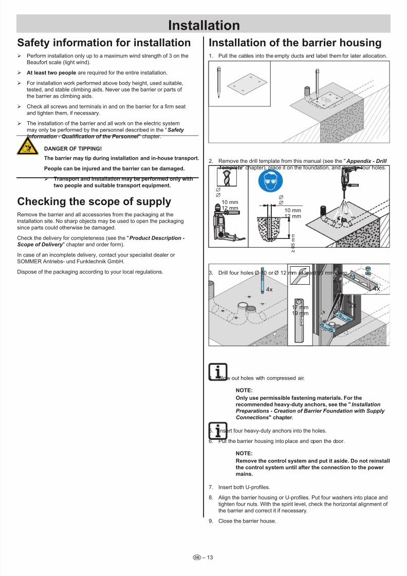
Istaatio of the barrier housig1. Pull the cables into the empty ducts and label them for later allocation.
2. Remove the drill template from this manual (see the " Appendix - Drill
Template" chapter), place it on the foundation, and draw in four holes.
10 mm12 mm
≥65mm
10 mm
12 mm
3. Drill four holes Ø 10 or Ø 12 mm at least 65 mm deep.
4x 4x
2x17 mm
19 mm
4. Blow out holes with compressed air.
nOTE:
Oy use permissibe fasteig materias. For the
recommeded heavy-duty achors, see the "InstallationPreparations - Creation of Barrier Foundation with Supply
Connections" chapter.
5. Insert four heavy-duty anchors into the holes.
6. Put the barrier housing into place and open the door.
nOTE:
Remove the cotro system ad put it aside. Do ot reista
the cotro system uti after the coectio to the power
mais.
7. Insert both U-proles.
8. Align the barrier housing or U-proles. Put four washers into place and
tighten four nuts. With the spirit level, check the horizontal alignment of the barrier and correct it if necessary.
9. Close the barrier house.
Istaatio
7/28/2019 Bariera SOOMER
http://slidepdf.com/reader/full/bariera-soomer 14/42
Istaatio
t – 14
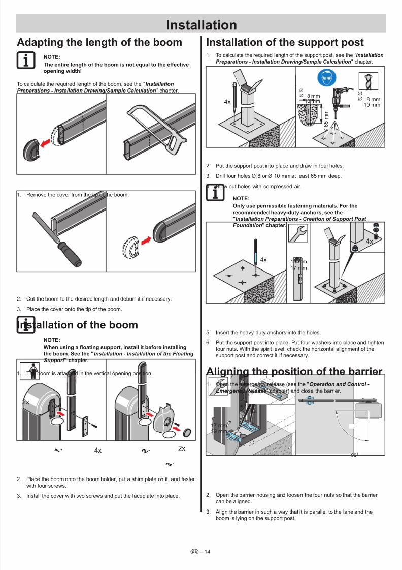
Adaptig the egth of the boom
nOTE:
The etire egth of the boom is ot equa to the effective
opeig width!
To calculate the required length of the boom, see the "Installation
Preparations - Installation Drawing/Sample Calculation" chapter.
1. Remove the cover from the tip of the boom.
2. Cut the boom to the desired length and deburr it if necessary.
3. Place the cover onto the tip of the boom.
Istaatio of the boom
nOTE:
When using a oating support, install it before installing
the boom. See the "Installation - Installation of the Floating
Support " chapter.
1. The boom is attached in the vertical opening position.
4x 2x
2x
2 . 1
.
3 .
2. Place the boom onto the boom holder, put a shim plate on it, and fasten
with four screws.
3. Install the cover with two screws and put the faceplate into place.
Istaatio of the support post1. To calculate the required length of the support post, see the "Installation
Preparations - Installation Drawing/Sample Calculation" chapter.
8 mm10 mm
≤65mm
10 mm
8 mm
4x
2. Put the support post into place and draw in four holes.
3. Drill four holes Ø 8 or Ø 10 mm at least 65 mm deep.
4. Blow out holes with compressed air.
nOTE:Oy use permissibe fasteig materias. For the
recommeded heavy-duty achors, see the
"Installation Preparations - Creation of Support Post
Foundation" chapter.
4x
13 mm
17 mm
4x
5. Insert the heavy-duty anchors into the holes.
6. Put the support post into place. Put four washers into place and tighten
four nuts. With the spirit level, check the horizontal alignment of the
support post and correct it if necessary.
Aigig the positio of the barrier 1. Open the emergency release (see the "Operation and Control -
Emergency Release" chapter) and close the barrier.
90°
17 mm
19 mm
2. Open the barrier housing and loosen the four nuts so that the barrier
can be aligned.
3. Align the barrier in such a way that it is parallel to the lane and theboom is lying on the support post.
7/28/2019 Bariera SOOMER
http://slidepdf.com/reader/full/bariera-soomer 15/42
Istaatio
t – 15
17 mm
19 mm
4. Tighten four nuts according to the requirements of the heavy-duty
anchor manufacturer.
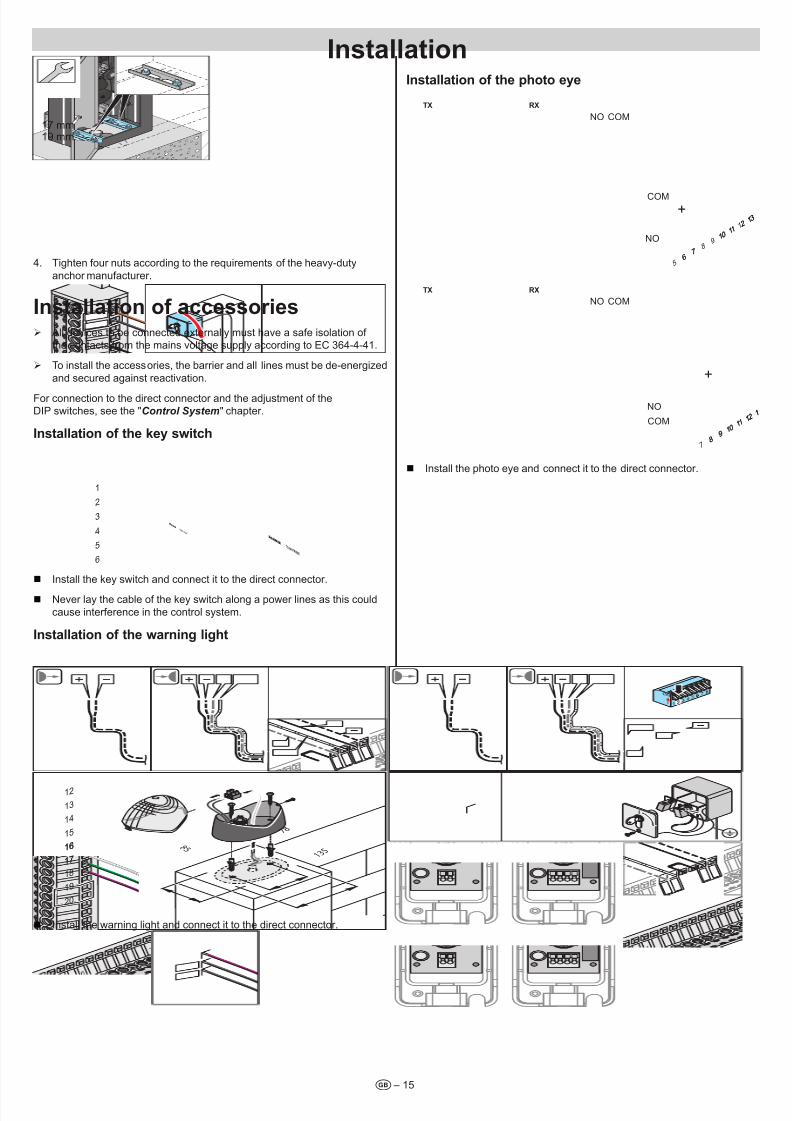
Istaatio of accessories ¾ All devices to be connected externally must have a safe isolation of
the contacts from the mains voltage supply according to EC 364-4-41.
¾ To install the accessories, the barrier and all lines must be de-energized
and secured against reactivation.
For connection to the direct connector and the adjustment of theDIP switches, see the "Control System" chapter.
Istaatio of the key switch
SOMMER TORANTRIEBE4
5
6
1
2
3
SOMMER TORANTRIEBE
Install the key switch and connect it to the direct connector.
Never lay the cable of the key switch along a power lines as this could
cause interference in the control system.
Istaatio of the warig ight
7 8
8 5
1 3 5
20
12
13
14
16
17
18
19
15
16
17
Install the warning light and connect it to the direct connector.
Istaatio of the photo eye
56
78
91 0
1 11 2
1 3
6
1 0
7
1 12
1 3
NO
TX RX
COM
+
NO
COM
78
91 0
1 11 2
1
8
1 0 9
1 11 2
1
NO
TX RX
COM
+
NO
COM
Install the photo eye and connect it to the direct connector.
7/28/2019 Bariera SOOMER
http://slidepdf.com/reader/full/bariera-soomer 16/42
Istaatio
t – 16
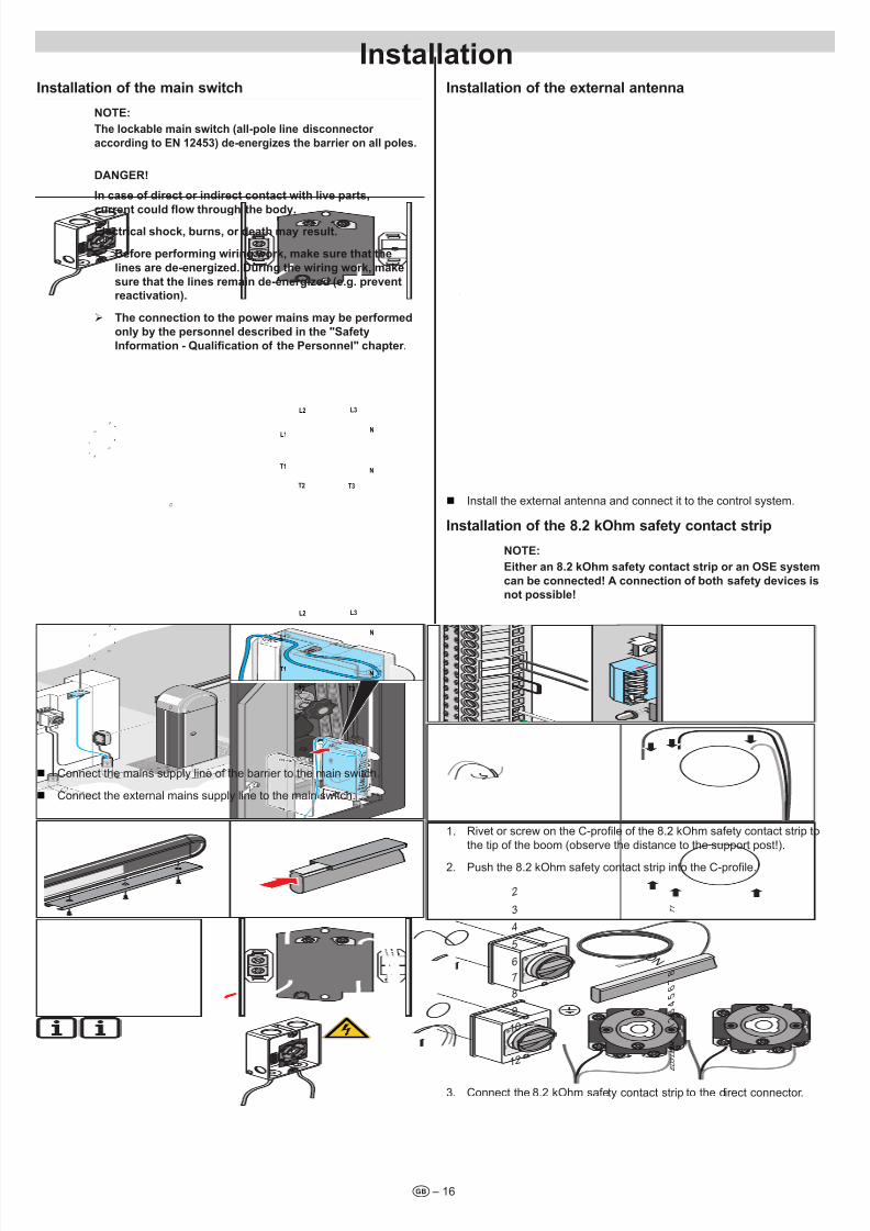
Istaatio of the mai switch
nOTE:
The lockable mai switch (all-pole lie discoector
accordig to En 12453) de-eergizes the barrier o all poles.
DAnGER!
I case of direct or idirect cotact with ive parts,
current could ow through the body.Eectrica shock, burs, or death may resut.
¾ Before performig wirig work, make sure that the
ies are de-eergized. Durig the wirig work, make
sure that the ies remai de-eergized (e.g. prevet
reactivatio).
¾ The coectio to the power mais may be performed
oy by the persoe described i the "Safety
Information - Qualication of the Personnel" chapter.
L1
L2
L3
T3
T2T1
N
N
O
L1
L2 L3
T3T2
T1
N
N
L1
L2
L3
T3
T2T1
N
N
O
L1
L2 L3
T3T2
T1
N
N
Connect the mains supply line of the barrier to the main switch.
Connect the external mains supply line to the main switch.
Istaatio of the extera atea
O
Install the external antenna and connect it to the control system.
Istaatio of the 8.2 kOhm safety cotact strip
nOTE:
Either a 8.2 kOhm safety cotact strip or a OSE system
ca be coected! A coectio of both safety devices is
ot possibe!
1. Rivet or screw on the C-prole of the 8.2 kOhm safety contact strip to
the tip of the boom (observe the distance to the support post!).
2. Push the 8.2 kOhm safety contact strip into the C-prole.
E D 3
L E D 4
T 1
O N
7 8
6 5 4 3 2 1
6
7
8
9
10
11
2
12
3
4
5
3. Connect the 8.2 kOhm safety contact strip to the direct connector.
7/28/2019 Bariera SOOMER
http://slidepdf.com/reader/full/bariera-soomer 17/42
Istaatio
t – 17
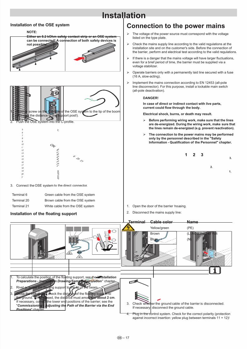
Istaatio of the OSE system
nOTE:
Either a 8.2 kOhm safety cotact strip or a OSE system
ca be coected! A coectio of both safety devices is
ot possibe!
1. Rivet or screw on the C-prole of the OSE system to the tip of the boom
(observe the distance to the support post!).
2. Push the OSE system into the C-prole.
6 2 0
2 1
E D 3
L E D 4
T 1
O N
7 8
6 5 4 3 2 1
5
7
8
9
10
11
16
17
18
19
20
21
12
13
14
15
6
3. Connect the OSE system to the direct connector.
Terminal 6 Green cable from the OSE system
Terminal 20 Brown cable from the OSE system
Terminal 21 White cable from the OSE system
Installation of the oating support
1. To calculate the position of the oating support, see the "Installation
Preparations - Installation Drawing/Sample Calculation" chapter.
2. Rivet or screw the oating support to the tip of the beam.
3. Close the barrier and check the distance of the oating support to
the ground. When closed, the distance must amount to about 2 cm.If necessary, correct the lower end positions of the barrier; see the
"Commissioning - Adjusting the Path of the Barrier via the End Positions" chapter.
Coectio to the power mais ¾ The voltage of the power source must correspond with the voltage
listed on the type plate.
¾ Check the mains supply line according to the valid regulations at the
installation site and on the customer's side. Before the connection of the barrier, perform and electrical test according to the valid regulations.
¾ If there is a danger that the mains voltage will have larger uctuations,
even for a brief period of time, the barrier must be supplied via avoltage stabilizer.
¾ Operate barriers only with a permanently laid line secured with a fuse
(16 A, slow-acting).
¾ Implement the mains connection according to EN 12453 (all-pole
line disconnector). For this purpose, install a lockable main switch
(all-pole deactivation).
DAnGER!
I case of direct or idirect cotact with ive parts,
current could ow through the body.
Eectrica shock, burs, or death may resut.
¾ Before performig wirig work, make sure that the lies
are de-eergized. Durig the wirig work, make sure that
the lies remai de-eergized (e.g. prevet reactivatio).
¾ The coectio to the power mais may be performed
oy by the persoe described i the "Safety
Information - Qualication of the Personnel" chapter.
1 2 3
2.
3.
1.
1. Open the door of the barrier housing.
2. Disconnect the mains supply line:
Termia Cabe coor name
1 Yellow/green (PE)
2 Brown (L) AC 220 - 240 Volt
3 Blue (N)
3. Check whether the ground cable of the barrier is disconnected.
If necessary, disconnect the ground cable.
4. Plug in the control system. Check for the correct polarity (protection
against incorrect insertion: yellow plug between terminals 11 + 12)!
7/28/2019 Bariera SOOMER
http://slidepdf.com/reader/full/bariera-soomer 18/42– 18t
Safety iformatio for istaatioThe barrier may not be commissioned until:
¾ The barrier is rmly and safety anchored in the foundation.
¾ All required monitoring units (for example, photo eyes) are correctly
connected.
¾ All accident prevention measures are performed.
¾ All safety provisions are observed.
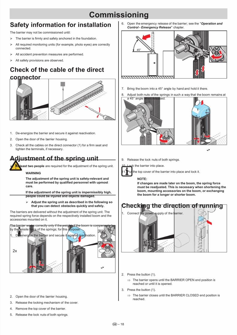
Check of the cabe of the direct
coector
1
1. De-energize the barrier and secure it against reactivation.
2. Open the door of the barrier housing.
3. Check all the cables on the direct connector (1) for a rm seat and
tighten the terminals, if necessary.
Adjustmet of the sprig uit ¾ At east two peope are required for the adjustment of the spring unit.
WARnInG
The adjustmet of the sprig uit is safety-reevat ad
must be performed by qualied personnel with upmost
care.
If the adjustmet of the sprig uit is impermissiby high,
peope coud be ijured ad objects damaged.
¾ Adjust the sprig uit as described i the foowig so
that you ca detect obstaces quicky ad safey.
The barriers are delivered without the adjustment of the spring unit. The
required spring force depends on the respectively installed boom and the
accessories mounted on it.
The barrier works correctly only if the weight of the boom is compensated
by the tensile force of the springs; for this purpose:
1. De-energize the barrier and secure it against reactivation.
2x1
2
2x
2. Open the door of the barrier housing.
3. Release the locking mechanism of the cover.
4. Remove the top cover of the barrier.
5. Release the lock nuts of both springs.
6. Open the emergency release of the barrier; see the "Operation and
Control - Emergency Release" chapter.
45°
7. Bring the boom into a 45° angle by hand and hold it there.
8. Adjust both nuts of the springs in such a way that the boom remains ata 45° angle when released.
1
2
9. Release the lock nuts of both springs.
10. Lock the barrier into place.
11. Put the top cover of the barrier into place and lock it.
nOTE:
If chages are made ater o the boom, the sprig force
must be readjusted. This is ecessary whe shorteig the
boom, moutig accessories o the boom, or exchagig
the boom for a oger or shorter boom.
Checkig the directio of ruig1. Connect the power supply of the barrier.
2. Press the button (1).
⇒ The barrier opens until the BARRIER OPEN end position is
reached or until it is opened.
3. Press the button (1).
⇒ The barrier closes until the BARRIER CLOSED end position isreached.
Commissioig
7/28/2019 Bariera SOOMER
http://slidepdf.com/reader/full/bariera-soomer 19/42
Commissioig
t – 19
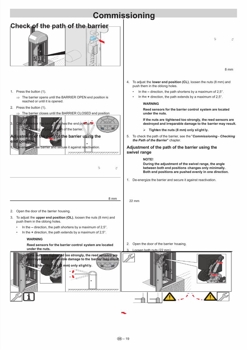
Check of the path of the barrier
1. Press the button (1).
⇒ The barrier opens until the BARRIER OPEN end position is
reached or until it is opened.
2. Press the button (1).
⇒ The barrier closes until the BARRIER CLOSED end position
is reached.
3. Check whether the barrier reaches the end positions.
⇒ If necessary, adjust the path of the barrier.
Adjustmet of the path of the barrier usig the
ed positio
1. De-energize the barrier and secure it against reactivation.
O L
C L
8 mm
2. Open the door of the barrier housing.
3. To adjust the upper ed positio (Ol), loosen the nuts (8 mm) and
push them in the oblong holes.
• In the – direction, the path shortens by a maximum of 2,5°.
• In the + direction, the path extends by a maximum of 2,5°.
WARnInG
Reed sesors for the barrier cotro system are ocateduder the uts.
If the uts are tighteed too strogy, the reed sesors are
destroyed ad irreparabe damage to the barrier may resut.
¾ Tighte the uts (8 mm) oy sight y.
O L
C L
8 mm
4. To adjust the ower ed positio (Cl), loosen the nuts (8 mm) and
push them in the oblong holes.
• In the – direction, the path shortens by a maximum of 2,5°.
• In the + direction, the path extends by a maximum of 2,5°.
WARnInG
Reed sesors for the barrier cotro system are ocated
uder the uts.
If the uts are tighteed too strogy, the reed sesors are
destroyed ad irreparabe damage to the barrier may resut.
¾ Tighte the uts (8 mm) oy sight y.
5. To check the path of the barrier, see the "Commissioning - Checking
the Path of the Barrier " chapter.
Adjustmet of the path of the barrier usig the
swive rage
nOTE!
Durig the adjustmet of the swive rage, the age
betwee both ed positios chages oy miimay.
Both ed positios are pushed evey i oe directio.
1. De-energize the barrier and secure it against reactivation.
22 mm
2. Open the door of the barrier housing.3. Loosen both nuts (22 mm).
7/28/2019 Bariera SOOMER
http://slidepdf.com/reader/full/bariera-soomer 20/42
Commissioig
t – 20
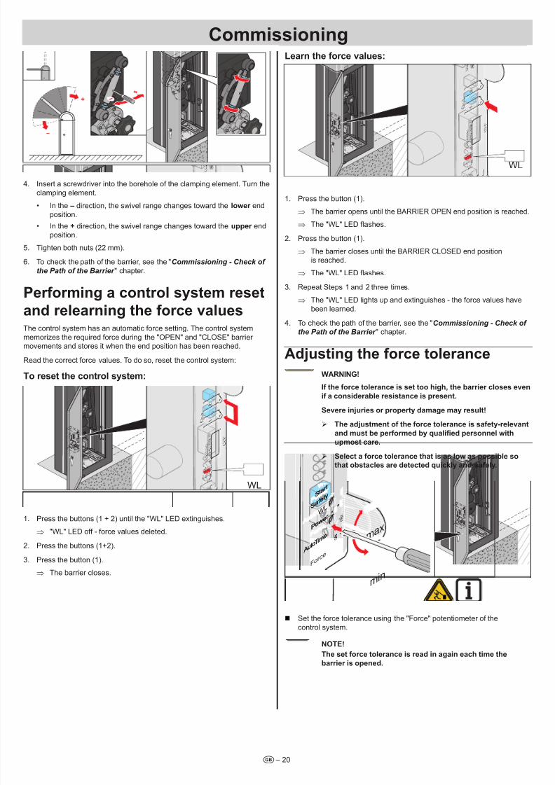
4. Insert a screwdriver into the borehole of the clamping element. Turn the
clamping element.
• In the – direction, the swivel range changes toward the ower end
position.
• In the + direction, the swivel range changes toward the upper end
position.
5. Tighten both nuts (22 mm).
6. To check the path of the barrier, see the "Commissioning - Check of
the Path of the Barrier " chapter.
Performig a cotro system reset
ad reearig the force vauesThe control system has an automatic force setting. The control system
memorizes the required force during the "OPEN" and "CLOSE" barrier movements and stores it when the end position has been reached.
Read the correct force values. To do so, reset the control system:
To reset the cotro system:
WL
1. Press the buttons (1 + 2) until the "WL" LED extinguishes.
⇒ "WL" LED off - force values deleted.
2. Press the buttons (1+2).
3. Press the button (1).
⇒ The barrier closes.
lear the force vaues:
WL
1. Press the button (1).
⇒ The barrier opens until the BARRIER OPEN end position is reached.
⇒ The "WL" LED ashes.
2. Press the button (1).
⇒ The barrier closes until the BARRIER CLOSED end position
is reached.
⇒ The "WL" LED ashes.
3. Repeat Steps 1 and 2 three times.
⇒ The "WL" LED lights up and extinguishes - the force values have
been learned.
4. To check the path of the barrier, see the "Commissioning - Check of
the Path of the Barrier " chapter.
Adjustig the force toerace
WARnInG!
If the force toerace is set too high, the barrier coses eve
if a cosiderabe resistace is preset.
Severe ijuries or property damage may resut! ¾ The adjustmet of the force toerace is safety-reevat
and must be performed by qualied personnel with
upmost care.
¾ Seect a force toerace that is as ow as possibe so
that obstaces are detected quicky ad safey.
O F
F
m a x .
O N
For ce
Saf et
yStar t
Powe
r WL
O F
F
m a x .
O N
For ce
Time
Auto
Auto
Saf et
yStar t
Powe
r WL
Time max
min
Set the force tolerance using the "Force" potentiometer of the
control system.
nOTE!
The set force toerace is read i agai each time the
barrier is opeed.
7/28/2019 Bariera SOOMER
http://slidepdf.com/reader/full/bariera-soomer 21/42– 21t
Safety iformatio for the remote
cotro ¾ The remote control may only be used for equipment and/or systems
where interference in the transmitter or receiver does not pose a risk
to humans, animals, or objects, or where the risk is covered by other
safety devices.
¾
The remote control may only be used in case of direct visual contactwith the barrier can be watched and no persons or objects are withinthe range of movement.
¾ Store the hand-held transmitter of the remote control in such a way so
that an unintended operation e.g., by children or animals, is prevented.
¾ The operator of the radio system is not protected from faults due toother telecommunications equipment or devices (e.g. radio systems,
which are being operated properly in the same frequency range).
In case of considerable interference, please contact the responsible
telephone exchange with radio interference measurement technology(radiolocation)!
¾ Do not operate the hand-held transmitter in areas with sensitive radio
communications or systems (e.g. airplanes, hospitals).
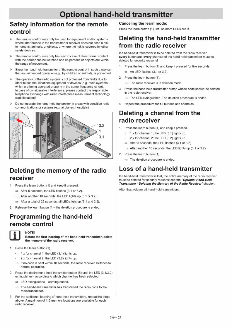
T 1
T 2
5
1
3.2
3.1
Deetig the memory of the radioreceiver 1. Press the learn button (1) and keep it pressed.
⇒ After 5 seconds, the LED ashes (3.1 or 3.2).
⇒ After another 10 seconds, the LED lights up (3.1 or 3.2).
⇒ After a total of 25 seconds, all LEDs light up (3.1 and 3.2).
2. Release the learn button (1) - the deletion procedure is ended.
Programmig the had-hed
remote cotro
nOTE!
Before the rst learning of the hand-held transmitter, delete
the memory of the radio receiver.
1. Press the learn button (1).
• 1 x for channel 1; the LED (3.1) lights up.
• 2 x for channel 2; the LED (3.2) lights up.
⇒ If no code is sent within 10 seconds, the radio receiver switches to
normal operation.
2. Press the desire hand-held transmitter button (5) until the LED (3.1/3.2)
extinguishes - according to which channel has been selected.
⇒ LED extinguishes - learning ended.
⇒ The hand-held transmitter has transferred the radio code to theradio transmitter.
3. For the additional learning of hand-held transmitters, repeat the steps
above. A maximum of 112 memory locations are available for each
radio receiver.
Caceig the ear mode:
Press the learn button (1) until no more LEDs are lit.
Deetig the had-hed trasmitter
from the radio receiver If a hand-held transmitter is to be deleted from the radio receiver,
every button and every shortcut of the hand-held transmitter must bedeleted for security reasons!
1. Press the learn button (1) and keep it pressed for ve seconds.
⇒ An LED ashes (3.1 or 3.2).
2. Press the learn button (1).
⇒ The radio receiver is in deletion mode.
3. Press the hand-held transmitter button whose code should be deletedin the radio receiver.
⇒ The LED extinguishes. The deletion procedure is ended.
4. Repeat the procedure for a buttons and shortcuts.
Deetig a chae from theradio receiver 1. Press the learn button (1) and keep it pressed.
• 1 x for channel 1; the LED (3.1) lights up.
• 2 x for channel 2; the LED (3.2) lights up.
⇒ After 5 seconds, the LED ashes (3.1 or 3.2).
⇒ After another 10 seconds, the LED lights up (3.1 or 3.2).
2. Press the learn button (1).
⇒ The deletion procedure is ended.
loss of a had-hed trasmitter If a hand-held transmitter is lost, the entire memory of the radio receiver
must be deleted for security reasons; see the "Optional Hand-Held
Transmitter - Deleting the Memory of the Radio Receiver " chapter.
After that, relearn all hand-held transmitters.
Optioa had-hed trasmitter
7/28/2019 Bariera SOOMER
http://slidepdf.com/reader/full/bariera-soomer 22/42– 22t
Safety iformatio o operatio ¾ The boom attachment is designed for wind strengths up to a maximum
of 8 on the Beaufort scale (stormy wind). In case of storm warnings
and wind strengths greater than 8 on the Beaufort scale, one of the
following must be performed in a timey manner:
– Close the barrier and de-energize it.
– Disassemble the boom.
¾ During normal operation:
– The upper cover of the barrier must be put into place and locked.
– The door of the barrier housing must be closed and locked.
¾ Before opening the barrier housing, de-energize all lines. In case of an
opened barrier housing, make sure that the lines remain de-energized.When the barrier housing is opened, risks arise due to the following:
– Tension springs under tension
– Crushing and scraping points in the vicinity of the drive connecting
rod and the linkage
¾ When the barrier housing is open, protect the control system and mains
supply lines from moisture.
¾ Operate the barrier only when all safety devices are present and fully
functional. As soon as a safety device is not functional, the barrier mustbe decommissioned until the malfunction has been properly eliminated.
¾ Do not let the barrier be used by several vehicles at once.
¾ Drive through the barrier only after it has opened completely.
¾ During operation, never hold the boom or reach into moving parts.
¾ During the opening and closing procedures, no people or objects may
be in the vicinity of the boom.
¾ The opening and closing procedures must be observed by the user.
¾ Do not place objects on the barrier housing or boom.
¾ Do not climb onto the barrier.
¾ The surface temperature of the motor may rise to 80°C, resulting in
a risk of burning.
Operatio with automatic cosig
fuctio ¾ During operation with automatic closing, observe the applicable
standards. Secure the closing level of the barrier with safety devices.
DAnGER
The automatic cosig fuctio without safety devices aso
coses the barrier if peope or objects are udereath.
Severe ijuries or property damage may resut.
¾ Ista the ecessary safety devices (photo eyes,
iductio oops, 8.2 kOhm safety cotact strip or
OSE system) accordig to En 12453.
In the case of the automatic closing function, the barrier closes
automatically after a set open time. The open time is counted down starting
when the BARRIER OPEN end position is reached. If another opening
command is made during the open time, the open time restarts.
The barrier can be opened, but not closed with a command initiator.
During opening, the barrier cannot be stopped using a command initiator.
If an opening command is made once again during the automatic closing
of the barrier, the barrier opens completely and the open time restarts.
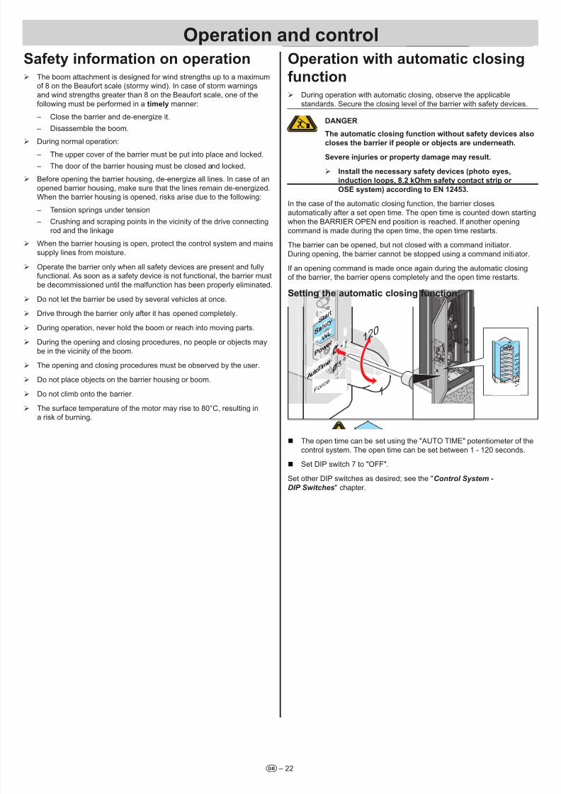
Settig the automatic cosig fuctio:
O F
F
m a x .
O N
For ce
Saf etyStar t
Powe
r WL
O F
F
m a x .
O N
For ce
Time
Auto
Auto
Saf etyStar t
Powe
r WL
Time
120
1
O N
7 8
6 5 4 3 2 1
O N
7 8
6 5 4 3 2 1
The open time can be set using the "AUTO TIME" potentiometer of the
control system. The open time can be set between 1 - 120 seconds.
Set DIP switch 7 to "OFF".
Set other DIP switches as desired; see the "Control System -
DIP Switches" chapter.
Operatio ad cotro
7/28/2019 Bariera SOOMER
http://slidepdf.com/reader/full/bariera-soomer 23/42
Operatio ad cotro
t – 23
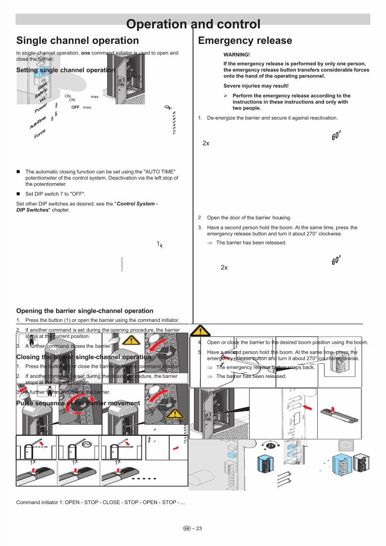
Sige chae operatioIn single-channel operation, oe command initiator is used to open andclose the barrier.
Settig sige chae operatio
O F
F
m a x .
O N
For ce
Saf ety
Star t
Powe
r WL
O F
F
m a x .
O N
For ce
Time
Auto
Auto
Saf ety
Star t
Powe
r WL
Time
O N
7 8
6 5 4 3 2 1
O N
7 8
6 5 4 3 2 1
OFF max.
ON
OFF
max.ON
The automatic closing function can be set using the "AUTO TIME"potentiometer of the control system. Deactivation via the left stop of
the potentiometer.
Set DIP switch 7 to "OFF".
Set other DIP switches as desired; see the "Control System -
DIP Switches" chapter.
7 8
6 5 4 3 2 1
1x
Opeig the barrier sige-chae operatio
1. Press the button (1) or open the barrier using the command initiator.
2. If another command is set during the opening procedure, the barrier
stops at the current position.
3. A further command closes the barrier.
Cosig the barrier sige-chae operatio
1. Press the button (1) or close the barrier using the command initiator.
2. If another command is set during the closing procedure, the barrier
stops at the current position.
3. A further command opens the barrier.
Puse sequece of the barrier movemet
S t a
r t
C o
1
2
S t a
r t
C o
1
2
O N
7 8
6 5 4 3 2 1
O N
7 8
6 5 4 3 2 1
7
1x 1x 1x
Command initiator 1: OPEN - STOP - CLOSE - STOP - OPEN - STOP - ...
Emergecy reease
WARnInG!
If the emergecy reease is performed by oy oe perso,
the emergecy reease butto trasfers cosiderabe forces
oto the had of the operatig persoe.
Severe ijuries may resut!
¾ Perform the emergecy reease accordig to theistructios i these istructios ad oy with
two peope.
1. De-energize the barrier and secure it against reactivation.
2x60
°
2. Open the door of the barrier housing.
3. Have a second person hold the boom. At the same time, press the
emergency release button and turn it about 270° clockwise.
⇒ The barrier has been released.
2x60
°
4. Open or close the barrier to the desired boom position using the boom.
5. Have a second person hold the boom. At the same time, press the
emergency release button and turn it about 270° counterclockwise.
⇒ The emergency release button snaps back.
⇒ The barrier has been released.
7/28/2019 Bariera SOOMER
http://slidepdf.com/reader/full/bariera-soomer 24/42– 24t
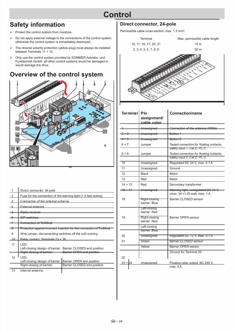
Safety iformatio ¾ Protect the control system from moisture.
¾ Do not apply external voltage to the connections of the control system,
otherwise the control system is immediately destroyed.
¾ The reverse polarity protection (yellow plug) must always be installed
between Terminals 11 + 12.
¾ Only use the control system provided by SOMMER Antriebs- undFunktechnik GmbH; all other control systems would be damaged or
would damage the drive.
Overview of the cotro system
L E D 1
L E D 2
L E D 3
L E D 4
T 1
P 2
T 2
1 2
6
7
8
9
10
543
13
12 11
1 Direct connector, 24-pole
2 Fuse for the connection of the warning light (1 A fast-acting)
3 Connection of the external antenna
4 External antenna
5 Radio receiver
6 DIP switches
7 Connection of TorMinal
8 Protection against incorrect insertion for the connection of TorMinal
9 Wire jumper, disconnecting switches off the soft running
10 Relay contact, Terminals 23 + 24
11 LED:
Left-closing design of barrier: Barrier CLOSED end position
Right-closing of barrier: Barrier OPEN end position
12 LED:
Left-closing design of barrier: Barrier OPEN end position
Right-closing of barrier: Barrier CLOSED end position
13 Internal antenna
Direct coector, 24-poe
Permissible cable cross-section: max. 1.5 mm².
Terminal Max. permissible cable length
10, 11, 16, 17, 20, 21 10 m
2, 3, 4, 5, 6, 7, 8, 9 30 m
2 32 2
2 12 0
1 91 8
1 71 6
1 51 4
1 31 2
1 11 0
98
76
54
3 2
1
2 4
Termia Pi
assigmet/
cabe coor
Coectio/ame
1 Unassigned Connection of the antenna 40MHz
2 + 3 Unassigned Button 1
4 + 5 Unassigned Button 2
6 + 7 Jumper Tested connection for oating contacts,
safety input 1, Cat 2 / PL C
8 + 9 Jumper Tested connection for oating contacts,
safety input 2, Cat 2 / PL C
10 Unassigned Regulated DC 24 V, max. 0.1 A
11 Unassigned Ground
12 Black Motor 13 Red Motor
14 + 15 Red Secondary transformer
16 + 17 Unassigned Warning light, unregulated DC 24 V(max. 34 V) 25 watt, max. 1 A
18 Right-closing
barrier: Blue
Barrier CLOSED sensor
Left-closingbarrier: Red
19 Right-closing
barrier: Red
Barrier OPEN sensor
Left-closingbarrier: Blue
20 Unassigned Regulated DC 12 V, max. 0.1 A
21 Green Barrier CLOSED sensor
Yellow Barrier OPEN sensor
- Ground for Terminal 20
22 - -
23 + 24 Unassigned Floating relay output, AC 230 V,max. 5 A
Cotro
7/28/2019 Bariera SOOMER
http://slidepdf.com/reader/full/bariera-soomer 25/42
Cotro
t – 25
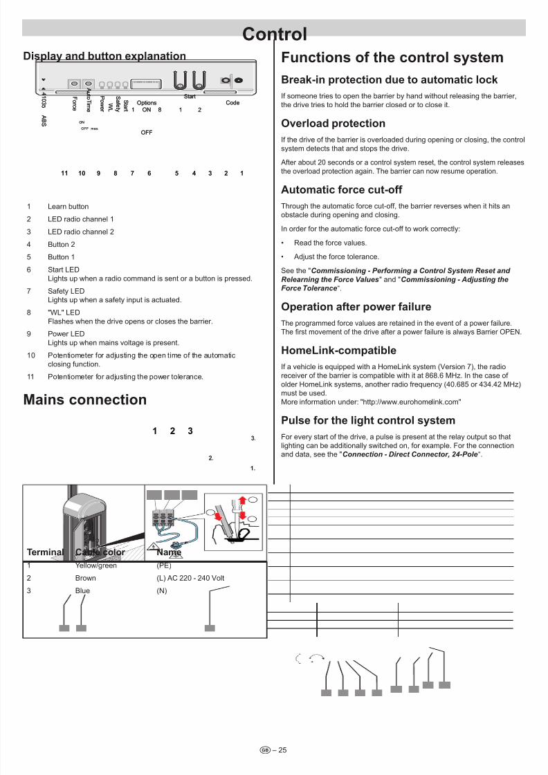
Dispay ad butto expaatio
StartCode
11 8ON
OFFOFF max.
ON
Options
4 1 0 3 5
F or c e
T i m e
A u t o S
af e t y
S t ar t
P ow er
WL
A B S
2
StartCode
11 8ON
OFFOFF max.
ON
Options
4 1 0 3 5
F or c e
T i m e
A u t o S
af e t y
S t ar t
P ow er
WL
A B S
2
1245678910 311
1 Learn button
2 LED radio channel 1
3 LED radio channel 2
4 Button 2
5 Button 1
6 Start LEDLights up when a radio command is sent or a button is pressed.
7 Safety LEDLights up when a safety input is actuated.
8 "WL" LED
Flashes when the drive opens or closes the barrier.
9 Power LED
Lights up when mains voltage is present.
10 Potentiometer for adjusting the open time of the automatic
closing function.
11 Potentiometer for adjusting the power tolerance.
Mais coectio1 2 3
2.
3.
1.
Termia Cabe coor name
1 Yellow/green (PE)
2 Brown (L) AC 220 - 240 Volt
3 Blue (N)
Fuctios of the cotro system
Break-i protectio due to automatic ock
If someone tries to open the barrier by hand without releasing the barrier,
the drive tries to hold the barrier closed or to close it.
Overoad protectio
If the drive of the barrier is overloaded during opening or closing, the control
system detects that and stops the drive.
After about 20 seconds or a control system reset, the control system releases
the overload protection again. The barrier can now resume operation.
Automatic force cut-off
Through the automatic force cut-off, the barrier reverses when it hits an
obstacle during opening and closing.
In order for the automatic force cut-off to work correctly:
• Read the force values.
• Adjust the force tolerance.
See the "Commissioning - Performing a Control System Reset and Relearning the Force Values" and "Commissioning - Adjusting the
Force Tolerance“.
Operatio after power faiure
The programmed force values are retained in the event of a power failure.
The rst movement of the drive after a power failure is always Barrier OPEN.
Homelik-compatibe
If a vehicle is equipped with a HomeLink system (Version 7), the radio
receiver of the barrier is compatible with it at 868.6 MHz. In the case of
older HomeLink systems, another radio frequency (40.685 or 434.42 MHz)
must be used.
More information under: "http://www.eurohomelink.com"
Puse for the ight cotro system
For every start of the drive, a pulse is present at the relay output so that
lighting can be additionally switched on, for example. For the connectionand data, see the "Connection - Direct Connector, 24-Pole“.
7/28/2019 Bariera SOOMER
http://slidepdf.com/reader/full/bariera-soomer 26/42
Cotro
t – 26
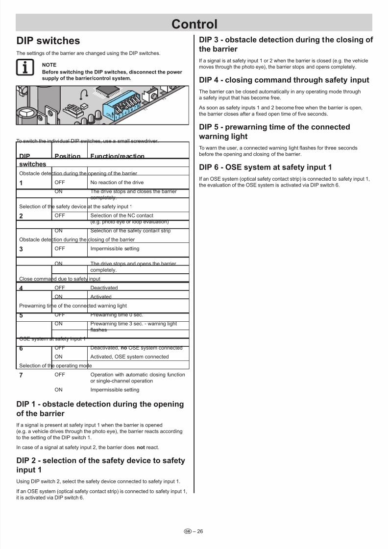
DIP switchesThe settings of the barrier are changed using the DIP switches.
nOTE
Before switchig the DIP switches, discoect the power
suppy of the barrier/cotro system.
T 1
T 2
To switch the individual DIP switches, use a small screwdriver.
DIP
switches
Positio Fuctio/reactio
Obstacle detection during the opening of the barrier
1 OFF No reaction of the drive
ON The drive stops and closes the barrier completely.
Selection of the safety device at the safety input 1
2 OFF Selection of the NC contact(e.g. photo eye or loop evaluation)
ON Selection of the safety contact strip
Obstacle detection during the closing of the barrier
3 OFF Impermissible setting
ON The drive stops and opens the barrier
completely.
Close command due to safety input
4 OFF Deactivated
ON Activated
Prewarning time of the connected warning light
5 OFF Prewarning time 0 sec.
ON Prewarning time 3 sec. - warning light
ashes
OSE system at safety input 1
6 OFF Deactivated, o OSE system connected
ON Activated, OSE system connected
Selection of the operating mode
7 OFF Operation with automatic closing function
or single-channel operation
ON Impermissible setting
DIP 1 - obstace detectio durig the opeig
of the barrier
If a signal is present at safety input 1 when the barrier is opened
(e.g. a vehicle drives through the photo eye), the barrier reacts according
to the setting of the DIP switch 1.
In case of a signal at safety input 2, the barrier does ot react.
DIP 2 - seectio of the safety device to safety
iput 1
Using DIP switch 2, select the safety device connected to safety input 1.
If an OSE system (optical safety contact strip) is connected to safety input 1,
it is activated via DIP switch 6.
DIP 3 - obstace detectio durig the cosig of
the barrier
If a signal is at safety input 1 or 2 when the barrier is closed (e.g. the vehicle
moves through the photo eye), the barrier stops and opens completely.
DIP 4 - cosig commad through safety iput
The barrier can be closed automatically in any operating mode through
a safety input that has become free.
As soon as safety inputs 1 and 2 become free when the barrier is open,
the barrier closes after a xed open time of ve seconds.
DIP 5 - prewarig time of the coected
warig ight
To warn the user, a connected warning light ashes for three seconds
before the opening and closing of the barrier.
DIP 6 - OSE system at safety iput 1
If an OSE system (optical safety contact strip) is connected to safety input 1,the evaluation of the OSE system is activated via DIP switch 6.
7/28/2019 Bariera SOOMER
http://slidepdf.com/reader/full/bariera-soomer 27/42– 27t
nOTE:
Usig this testig pa, test the barrier at the required itervas ad documet ad archive the test resut!
¾ Test interval using this test plan: annual.
¾ Test interval of the pressure-sensitive safety devices (e.g. 8.2 kOhm safety contact strip): every 4 - 6 weeks.
¾ The entire barrier is maintenance-free.
Testig Behavior Yes/
o
Possibe causes Remedy Date ad
tester
Force cut-off
Stop the boom at a closing
angle of about 45° when
closing with a 2 meter highobject.
The drive reverses
when it hits the object.
Yes The force cut-off works without
limitations.
Leave all settings as they are.
No Force tolerance too high. Set it
using the "Force" potentiometer or TorMinal.
Reduce the force tolerance until the test is successful.
Before that, open and close the barrier completelytwice under supervision. See the "Commissioning -
Adjusting the Force Tolerance" or "TorMinal
Instructions" chapter.
Emergecy reease
Proceed as describedin the "Operation and
Control - Emergency Release" chapter.
The barrier must beeasily opened/closed
by hand.
Yes Everything is OK!
No Emergency release defective. Have the emergency release repaired; call theCustomer Service of SOMMER Antriebs- und
Funktechnik GmbH for this purpose.
Visua ispectio
Check the boom and thebarrier housing for obvious
defects, damage fromvehicles, environmental
inuences, or vandalism.
The barrier showsdamage.
No Everything is OK!
Yes Boom or barrier housingdamaged.
Decommission the barrier and secure it againstreactivation.
Have the barrier or damaged parts repaired or
exchanged; call the Customer Service of SOMMER
Antriebs- und Funktechnik GmbH for this purpose.
Warning signs or reectors on
the barrier damaged.
Replace the warning signs or reectors.
8.2 kOhm safety cotact strip if preset
Close the barrier andactuate the 8.2 kOhmsafety contact strip in the
process.
Adjust the behavior of the barrier as in thecase of DIP switch
1 or 2.
Safety LED lights up.
Yes Everything is OK!
No Cable breakage, terminal loose. Check the wiring; retighten the terminals.
DIP switch adjusted. Set the DIP switch.
Strip defective. Decommission the barrier and secure against
reactivation; contact the Customer Service department
of SOMMER Antriebs- und Funktechnik GmbH.
Photo eye, if preset
Open/close the barrier,disconnecting the photo
eye in the process.
Adjust the behavior of
the barrier as in the
case of DIP switch1 or 2.
Safety LED lights up.
Yes Everything is OK!
No Cable breakage, terminal loose. Check the wiring; retighten the terminals.
DIP switch adjusted. Set the DIP switch.
Photo eye dirty. Clean the photo eye.
Photo eye adjusted (holder bent). Adjust the photo eyes.
Photo eye defective. Decommission the barrier and secure againstreactivation; contact the Customer Service department
of SOMMER Antriebs- und Funktechnik GmbH.
Iductio oop, if preset
Open/close the barrier,
disconnecting the
induction loop in theprocess.
Adjust the behavior of
the barrier as in the
case of DIP switch1 or 2.
Safety LED lights up.
Yes Everything is OK!
No Cable breakage, terminal loose. Check the wiring; retighten the terminals.
DIP switch adjusted. Set the DIP switch.
Induction loop defective. Decommission the barrier and secure itagainst reactivation.
Repair or exchange the induction loop or
damaged parts.
Sprig tesio
Bring the boom into a 45°
angle by hand and hold
it there.
The boom remains at
an angle of 45° when
released.
Yes Everything is OK!
No Incorrect spring setting Check and correct the spring setting; see the"Commissioning - Adjusting the Spring Unit " chapter.
Reguar testig ad maiteace
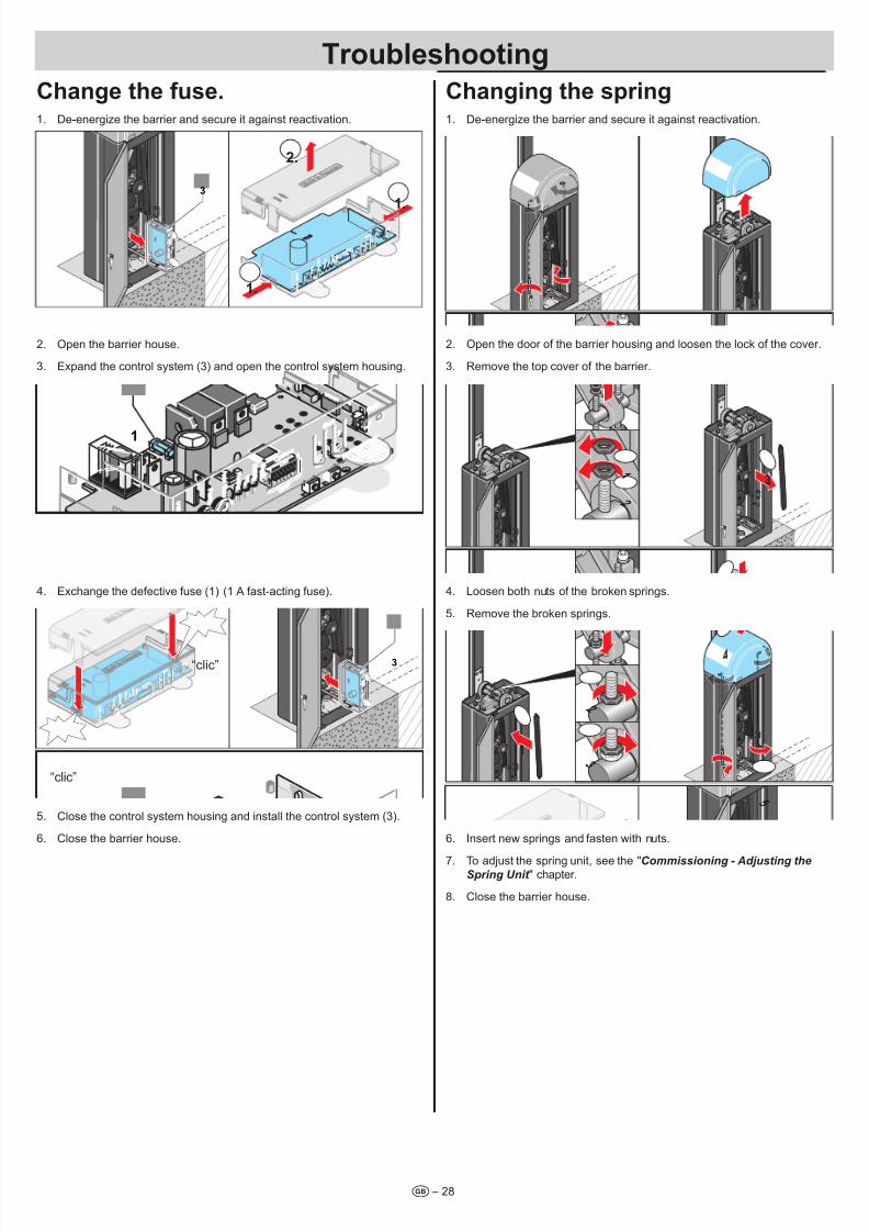
7/28/2019 Bariera SOOMER
http://slidepdf.com/reader/full/bariera-soomer 28/42– 28t
Chage the fuse.1. De-energize the barrier and secure it against reactivation.
2.
1.
1.
3
2. Open the barrier house.
3. Expand the control system (3) and open the control system housing.
L E D 1
L E D 2
L E D 3
L E D
4
T 1
T 2
1
4. Exchange the defective fuse (1) (1 A fast-acting fuse).
“clic”
“clic”
3
5. Close the control system housing and install the control system (3).
6. Close the barrier house.
Chagig the sprig1. De-energize the barrier and secure it against reactivation.
2. Open the door of the barrier housing and loosen the lock of the cover.
3. Remove the top cover of the barrier.
1
2
3
4. Loosen both nuts of the broken springs.
5. Remove the broken springs.
4
5
3
2
1
6. Insert new springs and fasten with nuts.
7. To adjust the spring unit, see the "Commissioning - Adjusting theSpring Unit " chapter.
8. Close the barrier house.
Troubeshootig
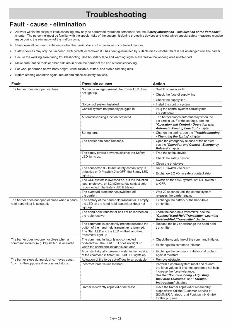
7/28/2019 Bariera SOOMER
http://slidepdf.com/reader/full/bariera-soomer 29/42– 29t
Faut - cause - eimiatio ¾ All work within the scope of troubleshooting may only be performed by trained personnel; see the "Safety Information - Qualication of the Personnel "
chapter. The personnel must be familiar with the special risks of the decommissioning protective devices and know which special safety measures must be
made during the elimination of the malfunctions.
¾ Shut down all command initiators so that the barrier does not move in an uncontrolled manner.
¾ Safety devices may only be jumpered, switched off, or removed if it has been guaranteed by suitable measures that there is still no danger from the barrier.
¾ Secure the working area during troubleshooting. Use boundary tape and warning signs. Never leave the working area unattended.
¾ Make sure that no tools or other aids are in or on the barrier at the end of troubleshooting.
¾ For work performed above body height, used suitable, tested, and stable climbing aids.
¾ Before starting operation again, mount and check all safety devices.
Faut Possibe causes Actio
The barrier does not open or close. No mains voltage present; the Power LED does
not light up.
• Switch on main switch.
• Check the fuse of supply line.
• Check the supply line.
No control system installed. • Install the control system
Control system not properly plugged in. • Plug the control system correctly into
the connector.
Automatic closing function activated. • The barrier closes automatically when the
set time is up. For the settings, see the
"Operation and Control - Operation with
Automatic Closing Function" chapter.
Spring torn. • Change the spring; see the "Troubleshooting
- Changing the Spring " chapter.
The barrier has been released. • Open the emergency release of the barrier;see the "Operation and Control - Emergency Release" chapter.
The safety device prevents closing; the Safety
LED lights up.• Free the safety device.
• Check the safety device.
• Clean the photo eye.
The connected 8.2 kOhm safety contact strip is
defective or DIP switch 2 is OFF; the Safety LEDlights up.
• Set DIP switch 2 to "ON".
• Exchange 8.2 kOhm safety contact strip.
The OSE system is switched on, but the induction
loop, photo eye, or 8.2 kOhm safety contact strip
is connected. The Safety LED lights up.
• Switch off the OSE system; set DIP switch 6
to OFF.
The overload protector has switched off
the barrier.• Wait 20 seconds until the control system
releases the barrier again.
The barrier does not open or close when a hand-held transmitter is actuated.
The battery of the hand-held transmitter is empty;the LED on the hand-held transmitter does not
light up.
• Exchange the battery of the hand-heldtransmitter.
The hand-held transmitter has not be learned on
the radio receiver.
• Learn the hand-held transmitter; see the"Optional Hand-Held Transmitter - Learning
the Hand-Held Transmitter " chapter.
The command is constantly present because thebutton of the hand-held transmitter is jammed.
The Start LED and the LED on the hand-heldtransmitter light up.
• Release the key or exchange the hand-heldtransmitter.
The barrier does not open or close when acommand initiator (e.g. key switch) is actuated.
The command initiator is not connectedor defective. The Start LED does not light up
when the command initiator is actuated.
• Check the supply line of the command initiator.
• Exchange the command initiator.
A constant signal is present - water in the housing
of the command initiator; the Start LED lights up.
• Exchange the command initiator and protect
against moisture.
The barrier stops during closing, moves about
10 cm in the opposite direction, and stops.
Actuation of the force cut-off due to an obstacle. • Remove obstacle.
Incorrect force values learned. • Perform a control system reset and relearn
the force values. If this measure does not help,
increase the force tolerance.
See the "Commissioning - Adjusting
the Force Tolerance" and "TorMinal
Instructions" chapters.
Barrier incorrectly adjusted or defective. • Have the barrier adjusted or repaired bya specialist; call the Customer Service of
SOMMER Antriebs- und Funktechnik GmbHfor this purpose.
Troubeshootig
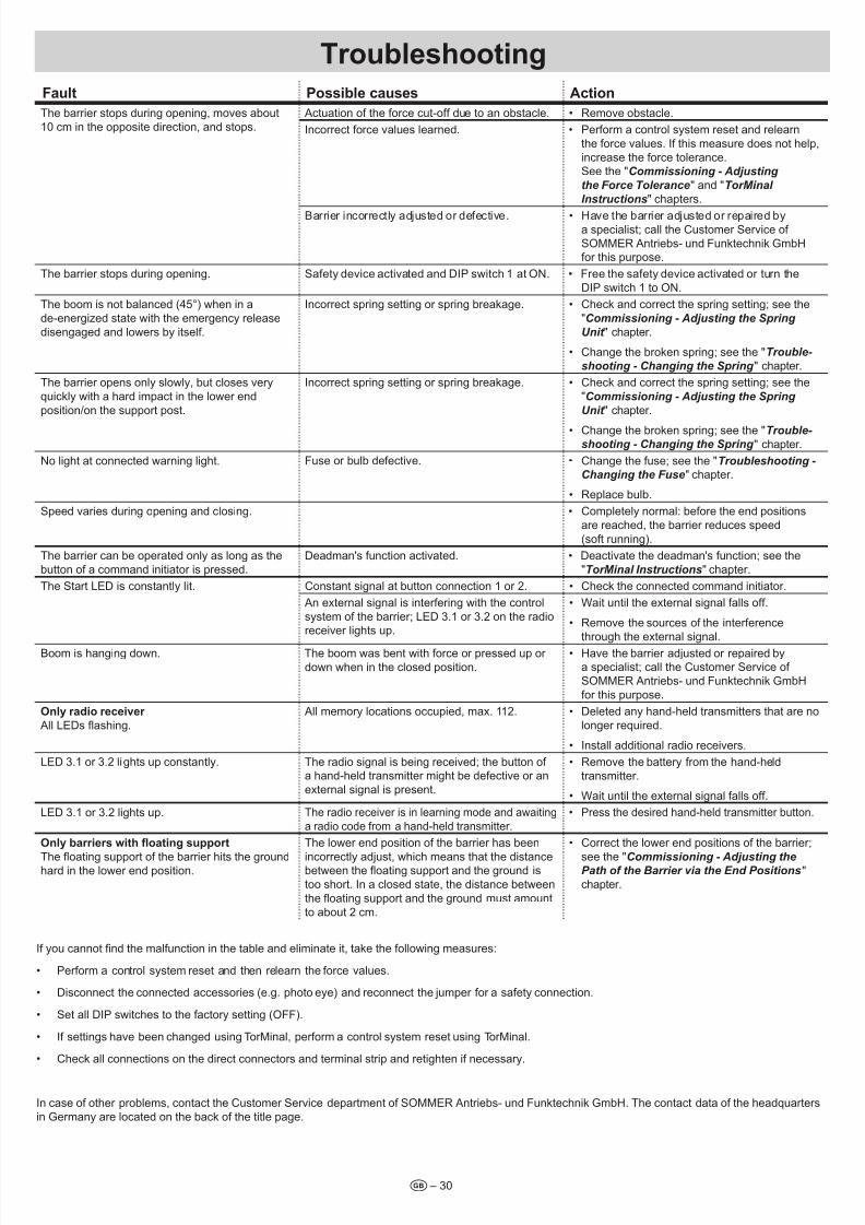
7/28/2019 Bariera SOOMER
http://slidepdf.com/reader/full/bariera-soomer 30/42
Troubeshootig
t – 30
Faut Possibe causes Actio
The barrier stops during opening, moves about
10 cm in the opposite direction, and stops.
Actuation of the force cut-off due to an obstacle. • Remove obstacle.
Incorrect force values learned. • Perform a control system reset and relearn
the force values. If this measure does not help,
increase the force tolerance.See the "Commissioning - Adjusting
the Force Tolerance" and "TorMinal
Instructions" chapters.
Barrier incorrectly adjusted or defective. • Have the barrier adjusted or repaired bya specialist; call the Customer Service of
SOMMER Antriebs- und Funktechnik GmbHfor this purpose.
The barrier stops during opening. Safety device activated and DIP switch 1 at ON. • Free the safety device activated or turn the
DIP switch 1 to ON.
The boom is not balanced (45°) when in a
de-energized state with the emergency release
disengaged and lowers by itself.
Incorrect spring setting or spring breakage. • Check and correct the spring setting; see the
"Commissioning - Adjusting the Spring
Unit " chapter.
• Change the broken spring; see the "Trouble-
shooting - Changing the Spring " chapter.
The barrier opens only slowly, but closes very
quickly with a hard impact in the lower end
position/on the support post.
Incorrect spring setting or spring breakage. • Check and correct the spring setting; see the
"Commissioning - Adjusting the Spring
Unit " chapter.
• Change the broken spring; see the "Trouble- shooting - Changing the Spring " chapter.
No light at connected warning light. Fuse or bulb defective. • Change the fuse; see the "Troubleshooting -
Changing the Fuse" chapter.
• Replace bulb.
Speed varies during opening and closing. • Completely normal: before the end positions
are reached, the barrier reduces speed
(soft running).
The barrier can be operated only as long as the
button of a command initiator is pressed.
Deadman's function activated. • Deactivate the deadman's function; see the
"TorMinal Instructions" chapter.
The Start LED is constantly lit. Constant signal at button connection 1 or 2. • Check the connected command initiator.
An external signal is interfering with the control
system of the barrier; LED 3.1 or 3.2 on the radioreceiver lights up.
• Wait until the external signal falls off.
• Remove the sources of the interference
through the external signal.
Boom is hanging down. The boom was bent with force or pressed up or
down when in the closed position.
• Have the barrier adjusted or repaired by
a specialist; call the Customer Service of
SOMMER Antriebs- und Funktechnik GmbH
for this purpose.
Oy radio receiver
All LEDs ashing.
All memory locations occupied, max. 112. • Deleted any hand-held transmitters that are no
longer required.
• Install additional radio receivers.
LED 3.1 or 3.2 lights up constantly. The radio signal is being received; the button of
a hand-held transmitter might be defective or an
external signal is present.
• Remove the battery from the hand-held
transmitter.
• Wait until the external signal falls off.
LED 3.1 or 3.2 lights up. The radio receiver is in learning mode and awaiting
a radio code from a hand-held transmitter.
• Press the desired hand-held transmitter button.
Only barriers with oating support
The oating support of the barrier hits the groundhard in the lower end position.
The lower end position of the barrier has been
incorrectly adjust, which means that the distancebetween the oating support and the ground is
too short. In a closed state, the distance between
the oating support and the ground must amount
to about 2 cm.
• Correct the lower end positions of the barrier;
see the "Commissioning - Adjusting thePath of the Barrier via the End Positions"chapter.
If you cannot nd the malfunction in the table and eliminate it, take the following measures:
• Perform a control system reset and then relearn the force values.
• Disconnect the connected accessories (e.g. photo eye) and reconnect the jumper for a safety connection.
• Set all DIP switches to the factory setting (OFF).
• If settings have been changed using TorMinal, perform a control system reset using TorMinal.
• Check all connections on the direct connectors and terminal strip and retighten if necessary.
In case of other problems, contact the Customer Service department of SOMMER Antriebs- und Funktechnik GmbH. The contact data of the headquarters
in Germany are located on the back of the title page.
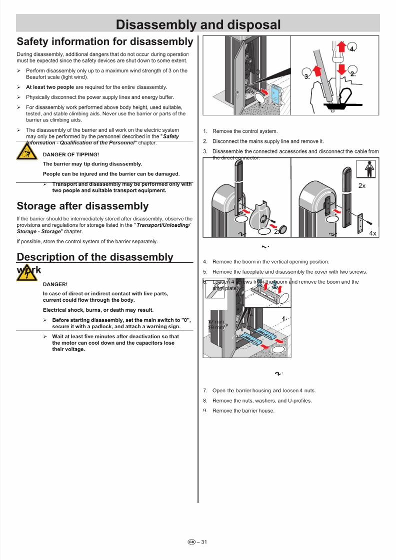
7/28/2019 Bariera SOOMER
http://slidepdf.com/reader/full/bariera-soomer 31/42– 31t
Safety iformatio for disassembyDuring disassembly, additional dangers that do not occur during operationmust be expected since the safety devices are shut down to some extent.
¾ Perform disassembly only up to a maximum wind strength of 3 on the
Beaufort scale (light wind).
¾ At east two peope are required for the entire disassembly.
¾ Physically disconnect the power supply lines and energy buffer.
¾ For disassembly work performed above body height, used suitable,
tested, and stable climbing aids. Never use the barrier or parts of the
barrier as climbing aids.
¾ The disassembly of the barrier and all work on the electric system
may only be performed by the personnel described in the "Safety
Information - Qualication of the Personnel " chapter.
DAnGER OF TIPPInG!
The barrier may tip durig disassemby.
Peope ca be ijured ad the barrier ca be damaged.
¾ Trasport ad disassemby may be performed oy with
two peope ad suitabe trasport equipmet.
Storage after disassembyIf the barrier should be intermediately stored after disassembly, observe the
provisions and regulations for storage listed in the "Transport/Unloading/
Storage - Storage" chapter.
If possible, store the control system of the barrier separately.
Descriptio of the disassemby
work
DAnGER!
I case of direct or idirect cotact with ive parts,current could ow through the body.
Eectrica shock, burs, or death may resut.
¾ Before startig disassemby, set the mai switch to "0",
secure it with a padock, ad attach a warig sig.
¾ Wait at least ve minutes after deactivation so that
the motor ca coo dow ad the capacitors ose
their votage.
3.
4.
2.
1.
1. Remove the control system.
2. Disconnect the mains supply line and remove it.
3. Disassemble the connected accessories and disconnect the cable from
the direct connector.
4x2x
2x
2 .
1 .
3 .
4. Remove the boom in the vertical opening position.
5. Remove the faceplate and disassembly the cover with two screws.
6. Loosen 4 screws from the boom and remove the boom and the
shim plate.
17 mm
19 mm
1.
2 .
7. Open the barrier housing and loosen 4 nuts.8. Remove the nuts, washers, and U-proles.
9. Remove the barrier house.
Disassemby ad disposa
7/28/2019 Bariera SOOMER
http://slidepdf.com/reader/full/bariera-soomer 32/42
Disassemby ad disposa
t – 32
DisposaThe disposal of the barrier, parts, operating materials, and adjuvants are
subject to legal regulations to some extent. Precise information can be
obtained from the responsible public administration authorities (e.g. water
resource and environmental protection ofces on a federal and state or
provincial level).
Deliver the goods to be disposed of only to authorized receiving point.
WARnInG
Evirometa damage i case of icorrect disposa!
¾ Eectrica scrap, eectrica compoets, ubricats,
ad other adjuvats are subject to treatmet as
hazardous materias ad may oy be disposed of by
approved speciaist compaies.

7/28/2019 Bariera SOOMER
http://slidepdf.com/reader/full/bariera-soomer 33/42
Appedix
EC Declaration of Conformity
in accordance with the Machinery Directive 2006/42/EC, appendix II, part 1
SOMMER Antriebs- und Funktechnik GmbH
Hans - Böckler - Straße 21 - 2773230 Kirchheim unter TeckGermany
hereby declares that the product
ASB 6010
complies with the Machinery Directive 2006/42/EC. The machine complies with all rules of the Directives for Electrical Appliances(2006/95/EC) and Electromagnetic Compatibility (2004/108/EC)
• The following fundamental safety requirements in accordance with appendix I have been applied and observed:
- General principles no. 1 - 1.2 Safety and reliability of control units
Safety input I terminals 6 + 7: Cat 2 / PL COptical Safety Edge terminals 6 + 20 + 21: Cat 2 / PL CElectrical Safety Edge 8,2 kΩ terminals 6 + 7: Cat 2 / PL CSafety input II terminals 8 + 9: Cat 2 / PL CInternal force limitation Cat 2 / PL C
Safety categories in accordance with EN 13849 - 1:2008
• Compliant with the regulations of the EC Building Products Guideline 89/106/EC.For the operating forces part, the respective initial testing has been carried out in consultation with recognized inspecting authori-ties. In doing so, the harmonized standards EN 13241-1, EN 12453 and EN 12445 have been applied. For the tested combina-tions, refer to the table „Reference list“ on the Internet under www.sommer.eu.
• Compliant with the Low Voltage Directive 2006/95/EC.• Konform ist mit der EMV - Richtlinie 2004/108/EG
• The technical documentation was drawn up in accordance with appendix VII A.
The product may only be put into operation after it has been established that the system complies with the regulations of the Machine-ry Directive.
Kirchheim, 29.12.2009
Jochen Luderesponsible for documents
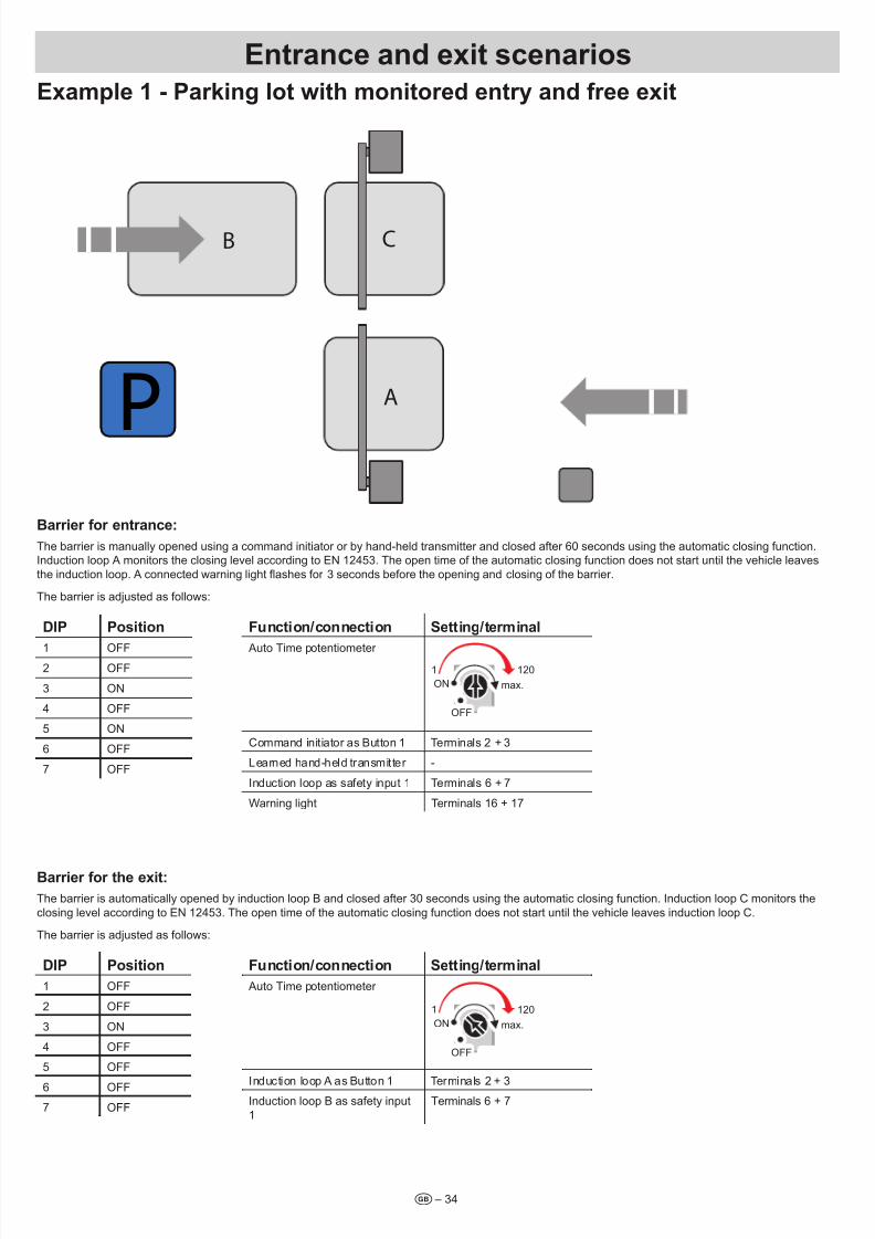
7/28/2019 Bariera SOOMER
http://slidepdf.com/reader/full/bariera-soomer 34/42– 34t
Exampe 1 - Parkig ot with moitored etry ad free exit
A
CB
P
Barrier for etrace:
The barrier is manually opened using a command initiator or by hand-held transmitter and closed after 60 seconds using the automatic closing function.Induction loop A monitors the closing level according to EN 12453. The open time of the automatic closing function does not start until the vehicle leaves
the induction loop. A connected warning light ashes for 3 seconds before the opening and closing of the barrier.
The barrier is adjusted as follows:
DIP Positio
1 OFF2 OFF
3 ON
4 OFF
5 ON
6 OFF
7 OFF
Fuctio/coectio Settig/termia
Auto Time potentiometer
OFF max.
ON
OFF
max.ON
1 120
Command initiator as Button 1 Terminals 2 + 3
Learned hand-held transmitter -
Induction loop as safety input 1 Terminals 6 + 7
Warning light Terminals 16 + 17
Barrier for the exit:
The barrier is automatically opened by induction loop B and closed after 30 seconds using the automatic closing function. Induction loop C monitors the
closing level according to EN 12453. The open time of the automatic closing function does not start until the vehicle leaves induction loop C.
The barrier is adjusted as follows:
DIP Positio
1 OFF
2 OFF
3 ON
4 OFF
5 OFF
6 OFF
7 OFF
Fuctio/coectio Settig/termia
Auto Time potentiometer
OFF max.
ON
OFF
max.ON
1 120
Induction loop A as Button 1 Terminals 2 + 3Induction loop B as safety input
1
Terminals 6 + 7
Etrace ad exit scearios
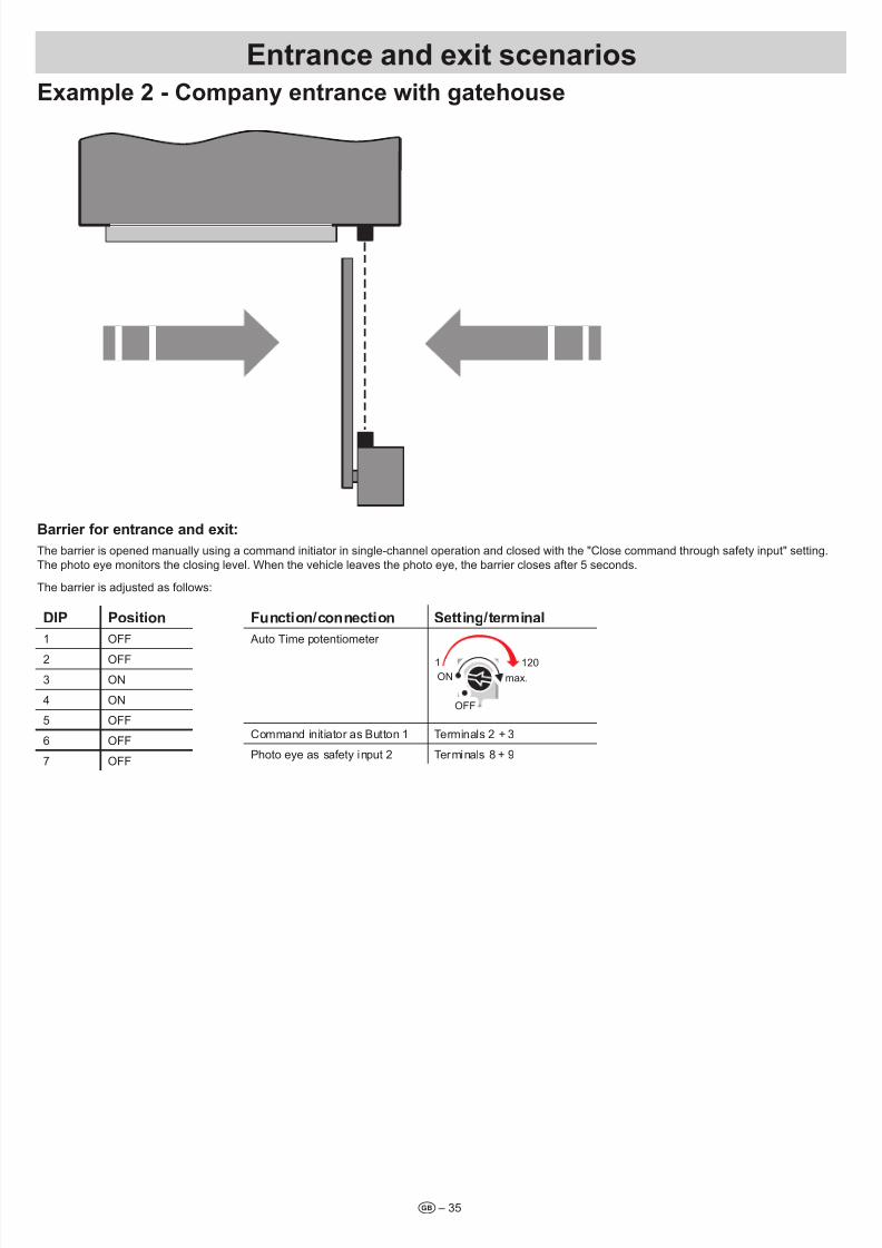
7/28/2019 Bariera SOOMER
http://slidepdf.com/reader/full/bariera-soomer 35/42– 35t
Etrace ad exit scearios
Exampe 2 - Compay etrace with gatehouse
Barrier for etrace ad exit:
The barrier is opened manually using a command initiator in single-channel operation and closed with the "Close command through safety input" setting.
The photo eye monitors the closing level. When the vehicle leaves the photo eye, the barrier closes after 5 seconds.
The barrier is adjusted as follows:
DIP Positio
1 OFF
2 OFF
3 ON
4 ON
5 OFF
6 OFF
7 OFF
Fuctio/coectio Settig/termia
Auto Time potentiometer
OFF max.
ON
OFF
max.ON
1 120
Command initiator as Button 1 Terminals 2 + 3
Photo eye as safety input 2 Terminals 8 + 9
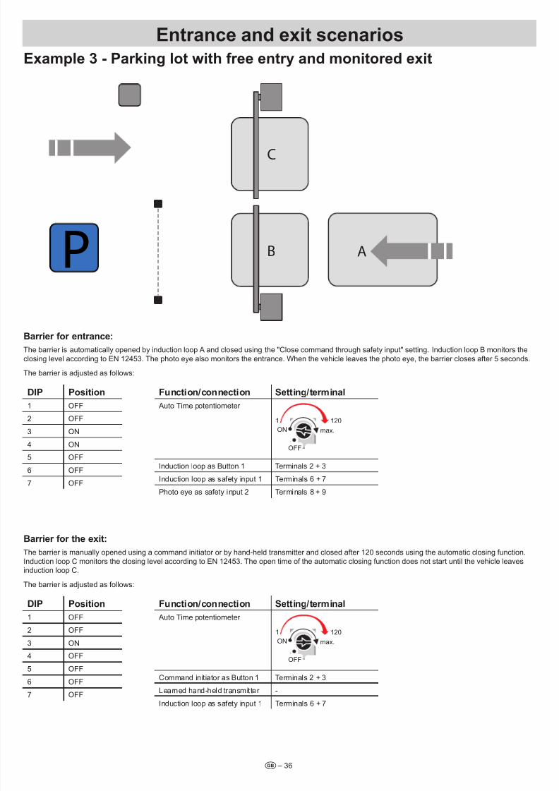
7/28/2019 Bariera SOOMER
http://slidepdf.com/reader/full/bariera-soomer 36/42– 36t
Etrace ad exit scearios
Exampe 3 - Parkig ot with free etry ad moitored exit
B
C
P A
Barrier for etrace:
The barrier is automatically opened by induction loop A and closed using the "Close command through safety input" setting. Induction loop B monitors the
closing level according to EN 12453. The photo eye also monitors the entrance. When the vehicle leaves the photo eye, the barrier closes after 5 seconds.
The barrier is adjusted as follows:
DIP Positio
1 OFF
2 OFF
3 ON
4 ON
5 OFF
6 OFF
7 OFF
Fuctio/coectio Settig/termia
Auto Time potentiometer
OFF max.
ON
OFF
max.ON
1 120
Induction loop as Button 1 Terminals 2 + 3
Induction loop as safety input 1 Terminals 6 + 7
Photo eye as safety input 2 Terminals 8 + 9
Barrier for the exit:
The barrier is manually opened using a command initiator or by hand-held transmitter and closed after 120 seconds using the automatic closing function.Induction loop C monitors the closing level according to EN 12453. The open time of the automatic closing function does not start until the vehicle leaves
induction loop C.
The barrier is adjusted as follows:
DIP Positio
1 OFF
2 OFF
3 ON
4 OFF
5 OFF
6 OFF
7 OFF
Fuctio/coectio Settig/termia
Auto Time potentiometer
OFF max.
ON
OFF
max.ON
1 120
Command initiator as Button 1 Terminals 2 + 3
Learned hand-held transmitter -Induction loop as safety input 1 Terminals 6 + 7

7/28/2019 Bariera SOOMER
http://slidepdf.com/reader/full/bariera-soomer 37/42
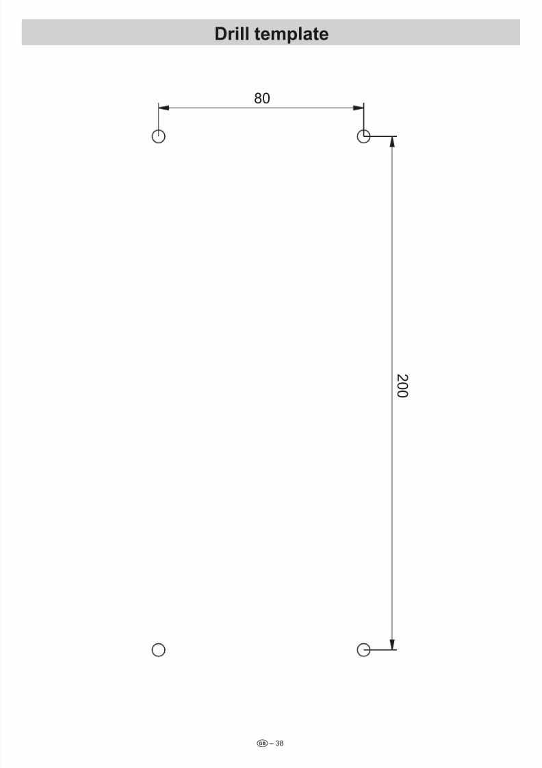
7/28/2019 Bariera SOOMER
http://slidepdf.com/reader/full/bariera-soomer 38/42– 38t
Dri tempate
2 0 0
80

7/28/2019 Bariera SOOMER
http://slidepdf.com/reader/full/bariera-soomer 39/42

7/28/2019 Bariera SOOMER
http://slidepdf.com/reader/full/bariera-soomer 40/42– 40t
Barrier hadover reportThe following barrier and its accessories were properly installed and the settings desired by the customer were made. The signing customer has been
trained in the operation and maintenance of the barrier and its accessories.
Type ASB 6010
Serial number
Handover date
Installation site e.g. construction site of Sommer
e.g. Hans-Böckler-Str. 21-27
e.g. D-73230 Kirchheim/Teck
Adjustmet of the barrier (DIP switch, Auto Time, etc.)
DIP 1 DIP 2 DIP 3 DIP 4 DIP 5 DIP 6 Auto Time
Accessories istaed o the barrier (photo eye, commad iitiator, etc.)
Customer address
Company
Name of customer
Street, house number
Postal code, city
The barrier listed above and its accessories were properly installed by a tter and handed over ready for operation. I have been trained in the operation,
maintenance, and function of the safety devices. The safety measures have been explained to me. The complete installation and operating manual has
been handed over in its entirety.
Date, customer's signature
Address of tter's rm
Company
Name of tter
Street, house number
Postal code, city
I have properly installed the barrier listed above and its accessories and handed it over ready for operation. I have trained the customer in the operation,
maintenance, and function of the safety devices. The safety measures have been explained to the customer. The complete installation and operating
manual has been handed over in its entirety.
Date, tter's signature

7/28/2019 Bariera SOOMER
http://slidepdf.com/reader/full/bariera-soomer 41/42
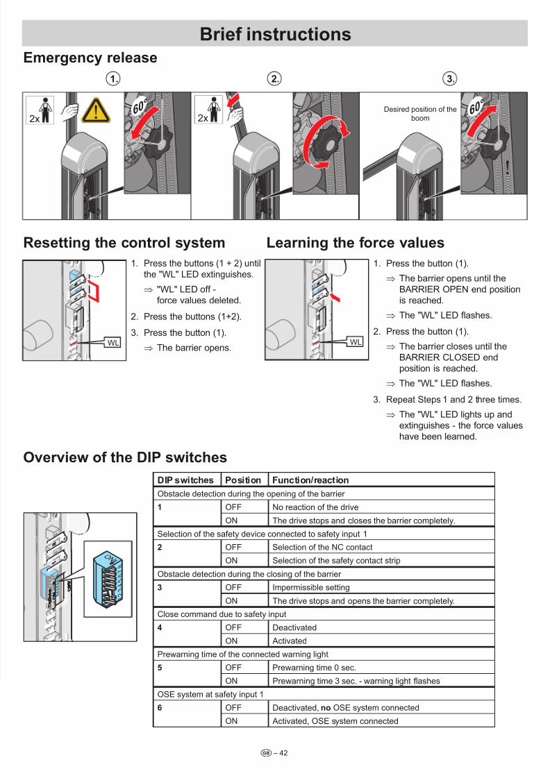
7/28/2019 Bariera SOOMER
http://slidepdf.com/reader/full/bariera-soomer 42/42
Emergecy reease
2.1. 3.
60°
60°
2x 2x
Resettig the cotro system learig the force vaues
WL
1. Press the buttons (1 + 2) until
the "WL" LED extinguishes.
⇒ "WL" LED off -force values deleted.
2. Press the buttons (1+2).
3. Press the button (1).
⇒ The barrier opens.WL
1. Press the button (1).
⇒ The barrier opens until theBARRIER OPEN end positionis reached.
⇒ The "WL" LED ashes.
2. Press the button (1).
⇒ The barrier closes until theBARRIER CLOSED endposition is reached.
⇒ The "WL" LED ashes.
3. Repeat Steps 1 and 2 three times.
⇒ The "WL" LED lights up andextinguishes - the force values
have been learned.
Overview of the DIP switches
DIP switches Positio Fuctio/reactio
Obstacle detection during the opening of the barrier
1 OFF No reaction of the drive
ON The drive stops and closes the barrier completely.
Selection of the safety device connected to safety input 1
2 OFF Selection of the NC contact
ON Selection of the safety contact strip
Obstacle detection during the closing of the barrier
3 OFF Impermissible setting
ON The drive stops and opens the barrier completely.
Close command due to safety input
4 OFF Deactivated
ON Activated
Prewarning time of the connected warning light
5 OFF Prewarning time 0 sec.
Brief istructios
7 8
6 5 4 3 2 1
O N
7 8
6 5 4 3 2 1
O N
7 8
6 5 4 3 2 1
Desired position of the
boom


![Szybki Monitoring NBP · 3 Szybki Monitoring NBP Uwarunkowania popytowe i sprzedaż Wykres 3 Bariera popytu (s.a.) i stopień wykorzystania mocy produkcyjnych (s.a.) [w %]78 Źródło:](https://img.pdfslide.tips/doc/110x75/5c76090d09d3f25d028b881f/szybki-monitoring-3-szybki-monitoring-nbp-uwarunkowania-popytowe-i-sprzedaz.jpg)