Embed Size (px)
Citation preview
Beyond 3G Challenges
David FalconerBroadband Communications and Wireless
Systems (BCWS) CentreDept. of Systems and Computer Engineering
Carleton University
[email protected]/bcws
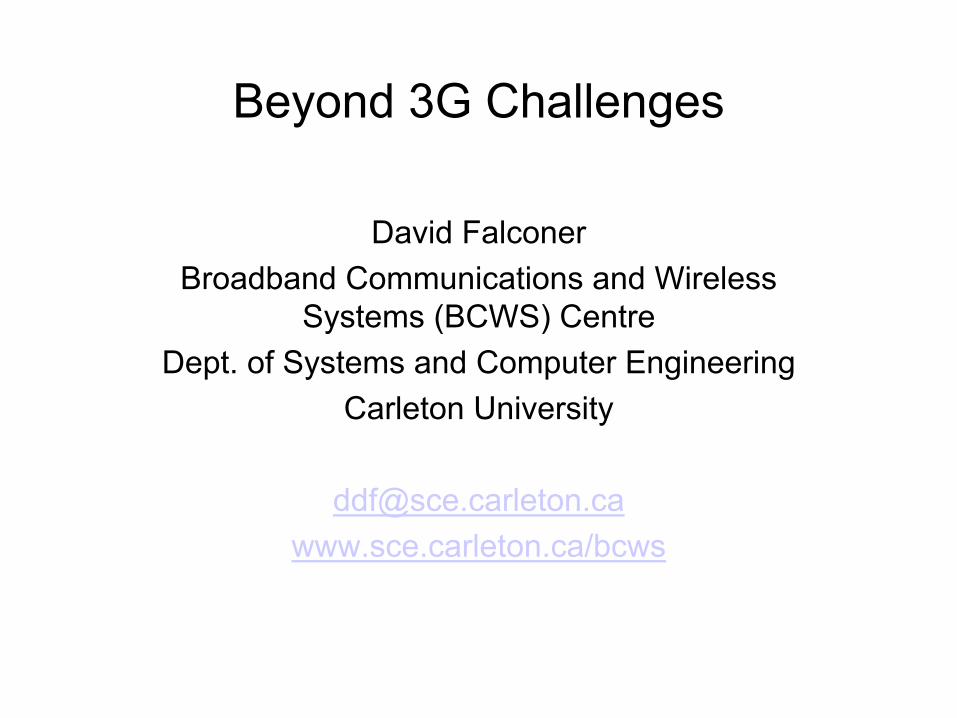
Outline
• What’s beyond 3G?• Some physical layer challenges• Frequency domain transmission/reception• Coverage enhancement by relay networks• Summary
What is Beyond 3G?
• Starting point is user needs.• IP-based, designed for data.• Ubiquitous seamless service.• > 10 times maximum speed of 3G, with about the
same allocated spectrum.• Also must accommodate high density of low-rate
device-to-device terminals (100’s of b/s).• Cheaper than 3G.• Smarter systems, evolving capabilities, according to
Moore’s law.
...faster bigger smarter handier closer cheaper friendlier smoother easier quicker better….
Physical Layer Challenges
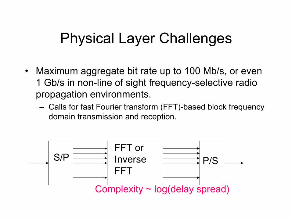
• Maximum aggregate bit rate up to 100 Mb/s, or even 1 Gb/s in non-line of sight frequency-selective radio propagation environments.– Calls for fast Fourier transform (FFT)-based block frequency
domain transmission and reception.
S/PFFT orInverseFFT
P/S
Complexity ~ log(delay spread)
Physical Layer Challenges (Cont.)
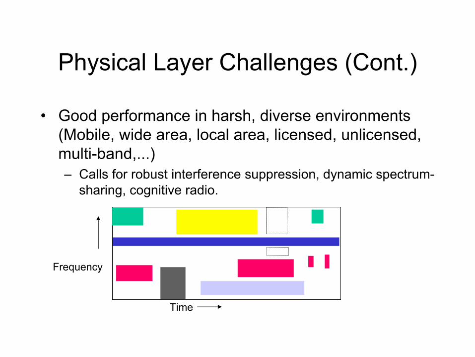
• Good performance in harsh, diverse environments (Mobile, wide area, local area, licensed, unlicensed, multi-band,...)– Calls for robust interference suppression, dynamic spectrum-
sharing, cognitive radio.
Time
Frequency
Physical Layer Challenges (Cont.)
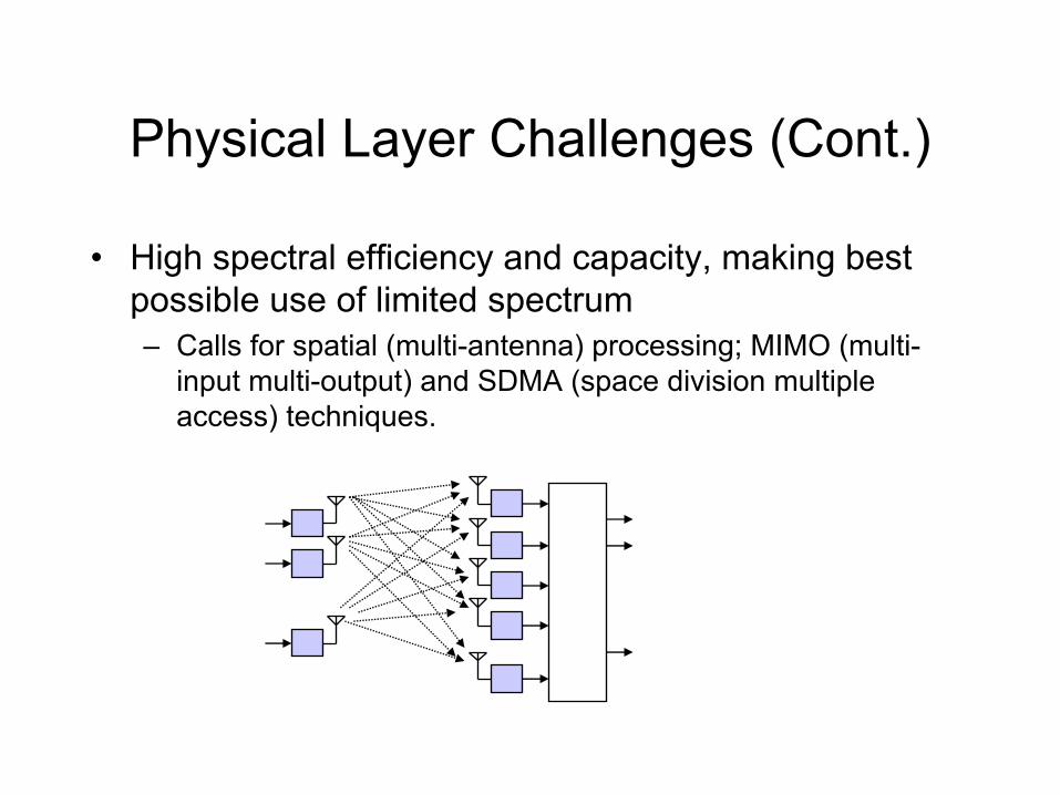
• High spectral efficiency and capacity, making best possible use of limited spectrum– Calls for spatial (multi-antenna) processing; MIMO (multi-
input multi-output) and SDMA (space division multiple access) techniques.
Physical Layer Challenges (Cont.)
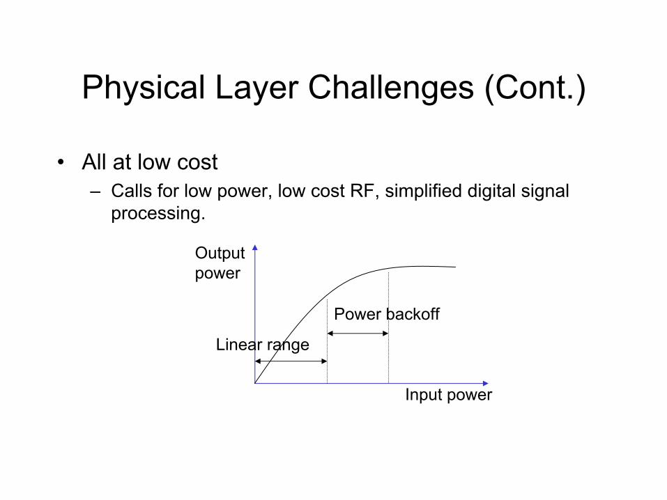
• All at low cost– Calls for low power, low cost RF, simplified digital signal
processing.
Input power
Outputpower
Power backoff
Linear range
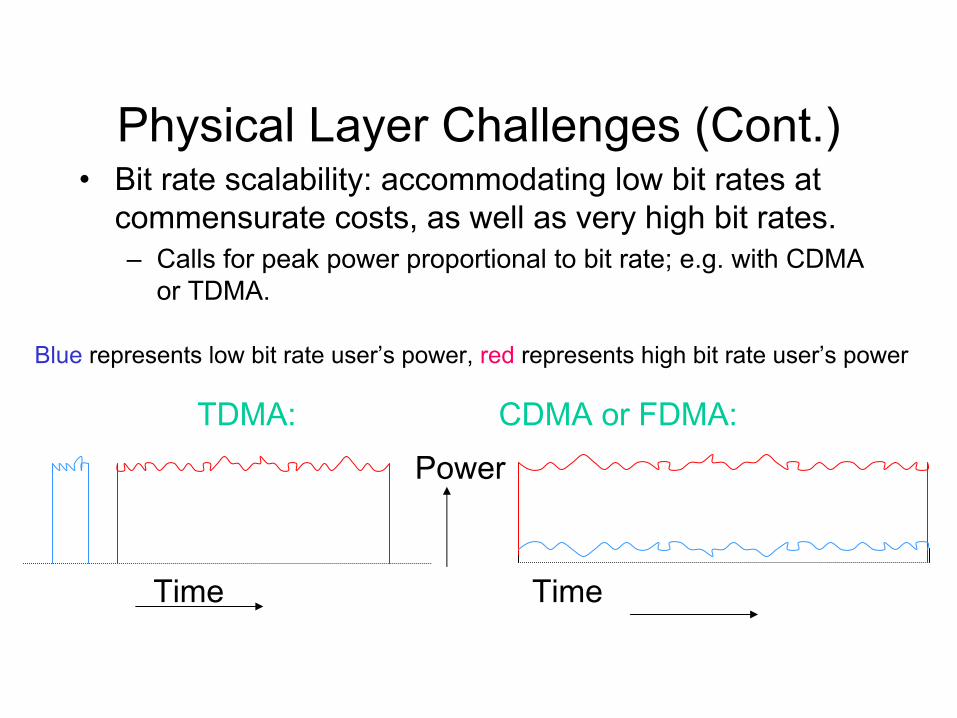
Physical Layer Challenges (Cont.)• Bit rate scalability: accommodating low bit rates at
commensurate costs, as well as very high bit rates.– Calls for peak power proportional to bit rate; e.g. with CDMA
or TDMA.
Time Time
TDMA: CDMA or FDMA:Power
Blue represents low bit rate user’s power, red represents high bit rate user’s power
Physical Layer Challenges (Cont.)
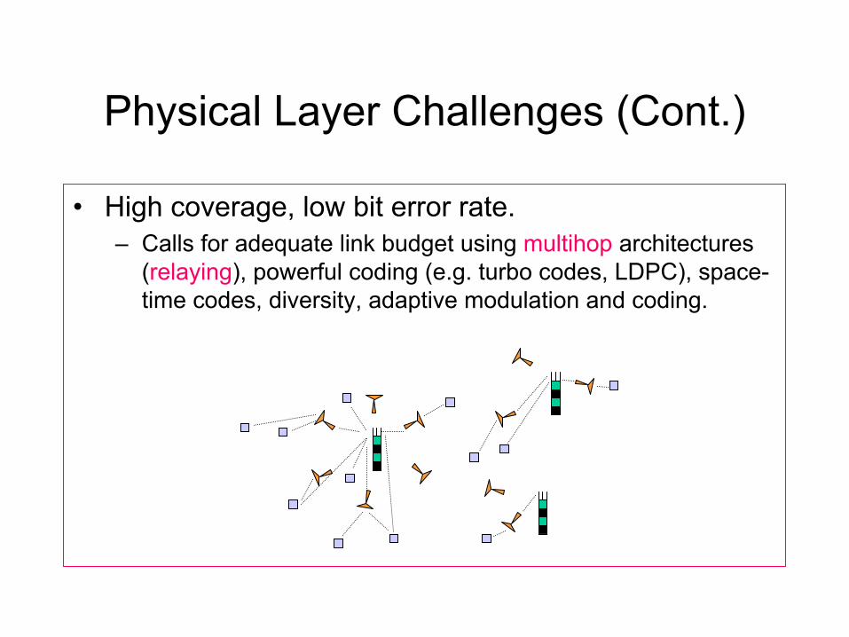
• High coverage, low bit error rate.– Calls for adequate link budget using multihop architectures
(relaying), powerful coding (e.g. turbo codes, LDPC), space-time codes, diversity, adaptive modulation and coding.
Physical Layer Challenges (Cont.)
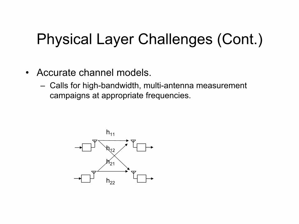
• Accurate channel models.– Calls for high-bandwidth, multi-antenna measurement
campaigns at appropriate frequencies.
h11
h12
h21
h22
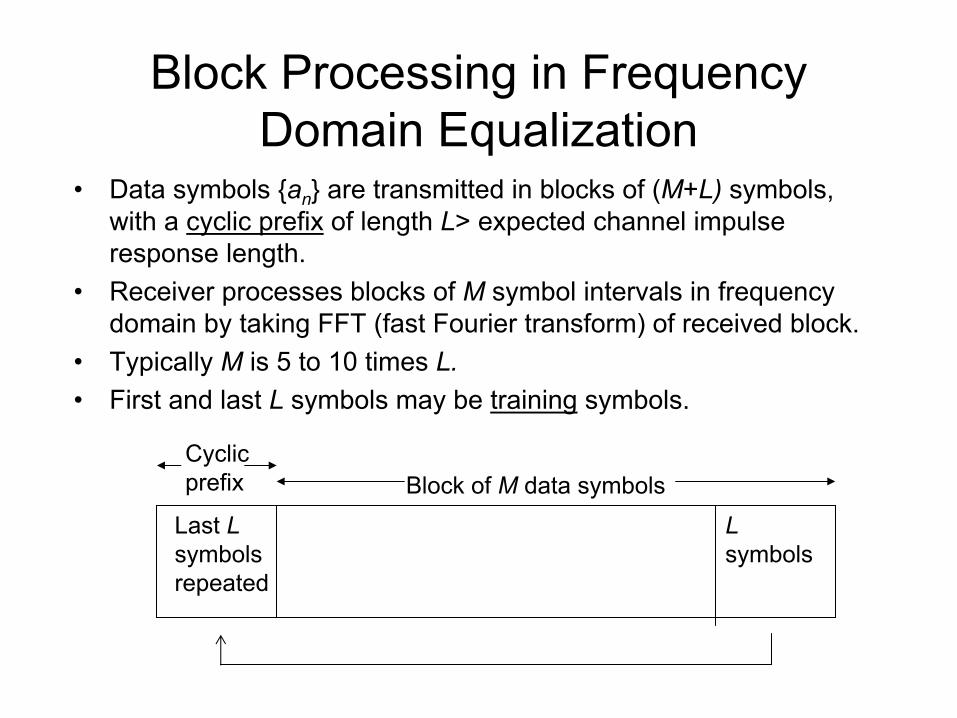
Block Processing in Frequency Domain Equalization
• Data symbols {an} are transmitted in blocks of (M+L) symbols, with a cyclic prefix of length L> expected channel impulse response length.
• Receiver processes blocks of M symbol intervals in frequency domain by taking FFT (fast Fourier transform) of received block.
• Typically M is 5 to 10 times L.• First and last L symbols may be training symbols.
Last Lsymbolsrepeated
Lsymbols
Block of M data symbolsCyclicprefix
0 10 20 30 40 50 60 700
20
40
60
80
100
120
140
Length of channel response
Num
ber o
f ope
ratio
ns p
er s
ymbo
l for
filte
ring
and
train
ing
Time domain linear equalizer
Frequency domain linear equalizer or OFDM
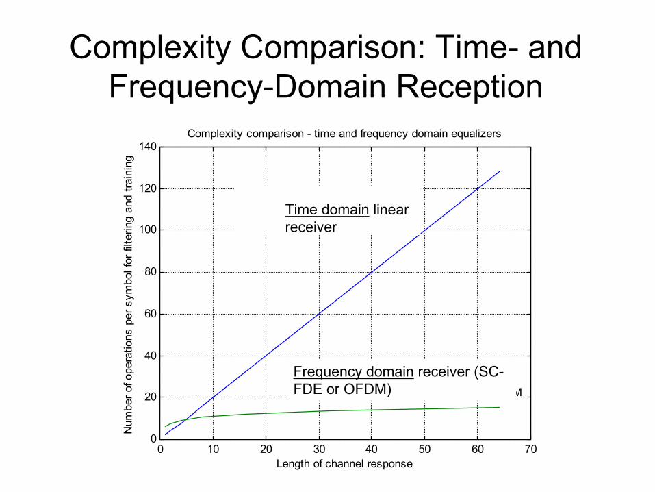
Complexity comparison - time and frequency domain equalizers
Time domain linearreceiver
Frequency domain receiver (SC-FDE or OFDM)
Complexity Comparison: Time- and Frequency-Domain Reception
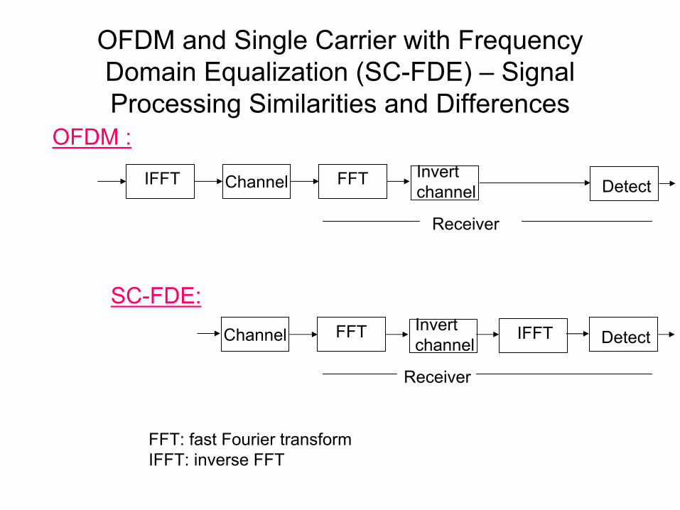
OFDM and Single Carrier with Frequency Domain Equalization (SC-FDE) – Signal Processing Similarities and Differences
ChannelIFFT FFT Invertchannel Detect
Channel IFFTFFT Invertchannel Detect
OFDM :
SC-FDE:
FFT: fast Fourier transformIFFT: inverse FFT
Receiver
Receiver
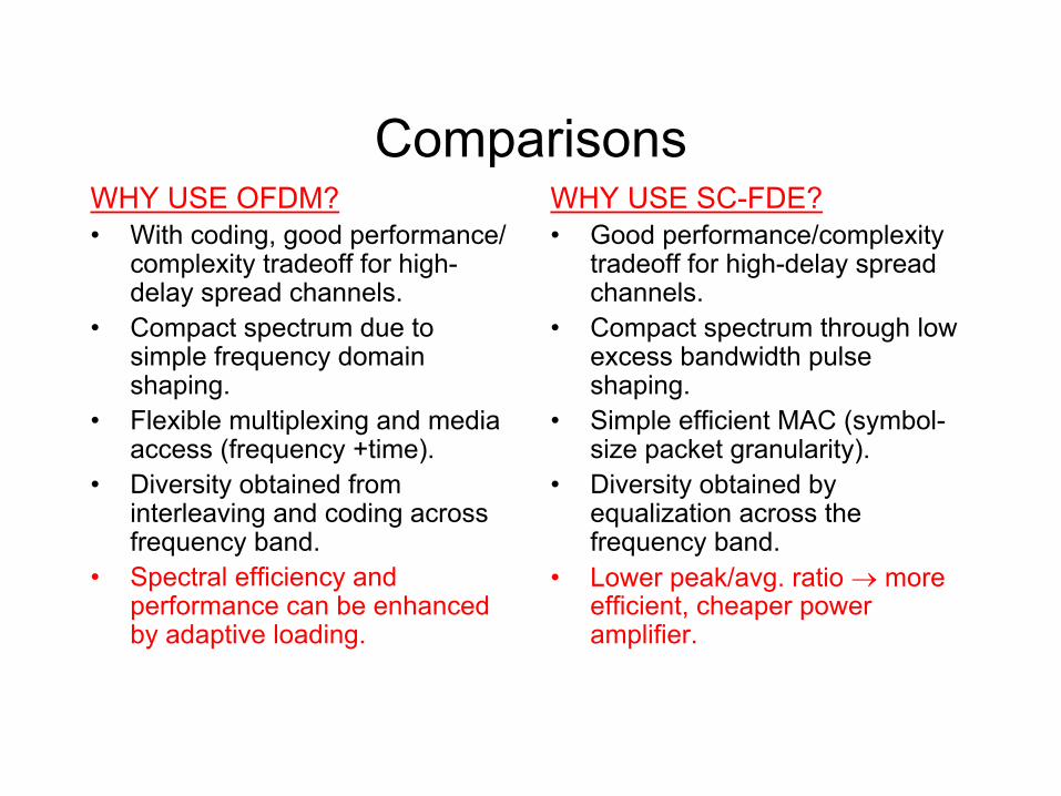
ComparisonsWHY USE OFDM?• With coding, good performance/
complexity tradeoff for high-delay spread channels.
• Compact spectrum due to simple frequency domain shaping.
• Flexible multiplexing and media access (frequency +time).
• Diversity obtained from interleaving and coding across frequency band.
• Spectral efficiency and performance can be enhanced by adaptive loading.
WHY USE SC-FDE?• Good performance/complexity
tradeoff for high-delay spread channels.
• Compact spectrum through low excess bandwidth pulse shaping.
• Simple efficient MAC (symbol-size packet granularity).
• Diversity obtained by equalization across the frequency band.
• Lower peak/avg. ratio → more efficient, cheaper power amplifier.
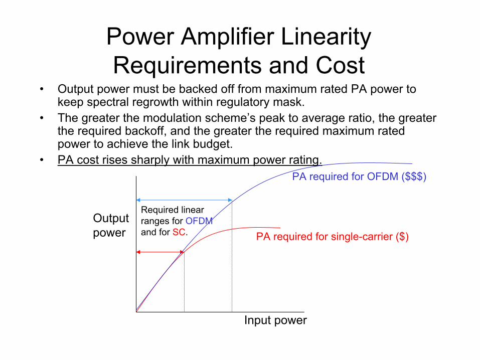
Power Amplifier Linearity Requirements and Cost
• Output power must be backed off from maximum rated PA power to keep spectral regrowth within regulatory mask.
• The greater the modulation scheme’s peak to average ratio, the greater the required backoff, and the greater the required maximum rated power to achieve the link budget.
• PA cost rises sharply with maximum power rating.
Input power
Outputpower
Required linearranges for OFDMand for SC.
PA required for OFDM ($$$)
PA required for single-carrier ($)
OFDM in the Downlink, SC in the Uplink
• The subscriber transmitter is single carrier (SC), and thus is inherently more efficient in terms of power consumption, due to the reduced power back-off requirements of the single carrier mode. This will reduce the cost of a subscriber’s power amplifier.
• Most of the signal processing complexity is cost-effectively concentrated at the hub, or base station. The hub has twoIFFT’s and one FFT, while the subscriber has just one FFT.
• OFDM in the downlink can exploit adaptive loading of subchannels for high efficiency and performance, and can multiplex users in both time and frequency.
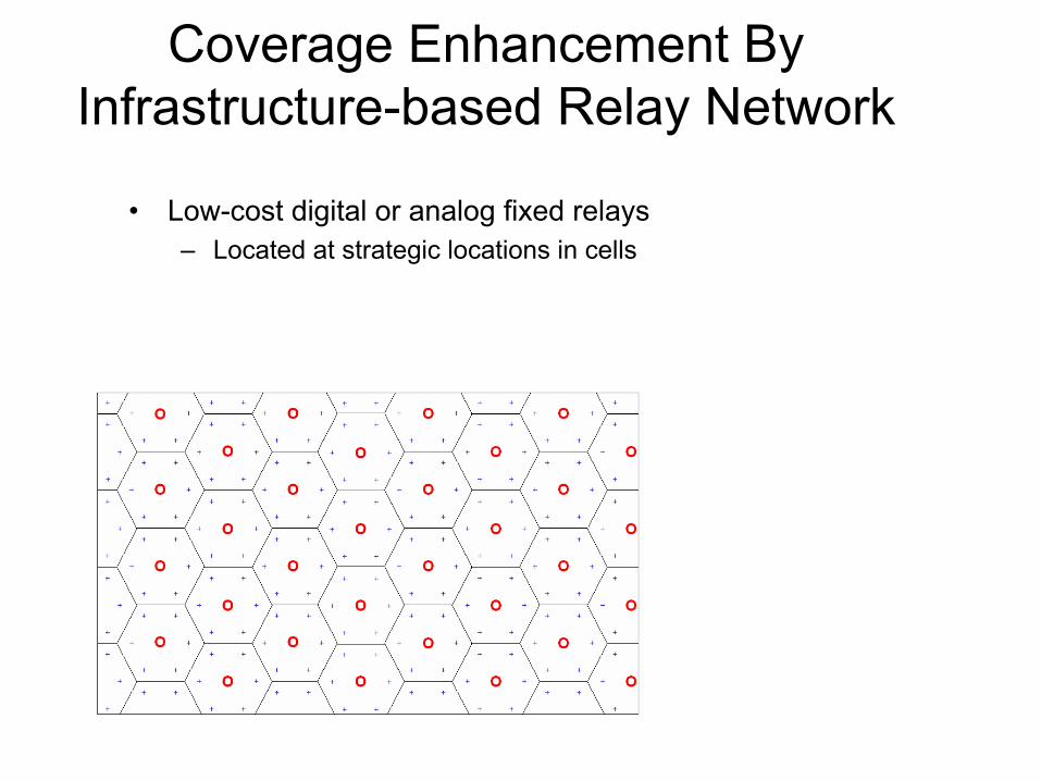
Coverage Enhancement By Infrastructure-based Relay Network
• Low-cost digital or analog fixed relays– Located at strategic locations in cells
0 5 10 15 20 25 30(dB)0.1
0.2
0.3
0.4
0.5
0.6
0.7
0.8
0.9
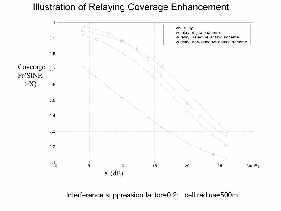
1w/o relayw relay, digital schemew relay, selective analog schemew relay, non-selective analog scheme
X (dB)
Coverage:Pr(SINR
>X)
Interference suppression factor=0.2; cell radius=500m.
Illustration of Relaying Coverage Enhancement
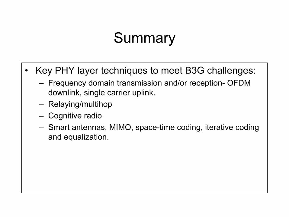
Summary
• Key PHY layer techniques to meet B3G challenges:– Frequency domain transmission and/or reception- OFDM
downlink, single carrier uplink.– Relaying/multihop– Cognitive radio– Smart antennas, MIMO, space-time coding, iterative coding
and equalization.

EXTRA SLIDES
References
• WWRF Book of Visions [www.wireless-world-research.org]• D. Falconer, S.L. Ariyavisitakul, A. Benyamin-Seeyar and B. Eidson, “Frequency Domain
Equalization for Single-Carrier Broadband Wireless Systems”, IEEE Communications Magazine, Vol. 40, No. 4, April 2002, pp. 58-66.
• D. Falconer and S.L. Ariyavisitakul, "Broadband Wireless Using Single Carrier and Frequency Domain Equalization", Proc. 5th Int. Symposium on Wireless Personal Multimedia Communications, Honolulu, Oct. 27-30, 2002.
• D. Falconer, R. Dinis, C.T. Lam and M. Sabbaghian, “Frequency Domain Orthogonal signature Sequences (FDOSS) for Uplink DS-CDMA”, Proc. 10th WWRF Symposium, New York, Oct. 2003.
• H. Yanikomeroglu and H. Hu, “Performance Analysis of Cellular radio Networks with Fixed Relays”, Proc. 10th WWRF Symposium, New York, Oct. 2003.
• W. Mohr, R. Lüder amd K-H. Möhrmann, "Data Rate Estimates, Range Calculations and Spectrum Demand for New Elements of Systems Beyond IMT-2000", Proc. 5th Int. Symposium on Wireless Personal Multimedia Communications, Honolulu, Oct. 27-30, 2002.
• H. Sari, G. Karam and I. Jeanclaude, “Frequency-Domain Equalization of Mobile Radio and Terrestrial Broadcast Channels”, Proc. Globecom ’94, San Francisco, Nov.-Dec. 1994, pp. 1-5.
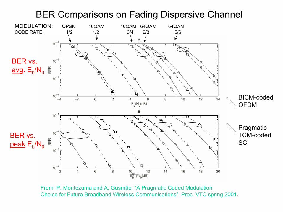
BER Comparisons on Fading Dispersive Channel
From: P. Montezuma and A. Gusmão, “A Pragmatic Coded Modulation Choice for Future Broadband Wireless Communications”, Proc. VTC spring 2001.
MODULATION: QPSK 16QAM 16QAM 64QAM 64QAM CODE RATE: 1/2 1/2 3/4 2/3 5/6
BICM-codedOFDM
PragmaticTCM-codedSC
BER vs.avg. Eb/N0
BER vs.peak Eb/N0
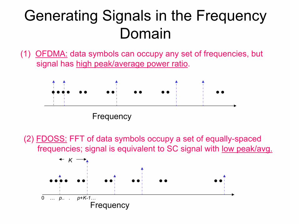
Generating Signals in the Frequency Domain
K
0 … p.. . p+K-1…Frequency
Frequency
(1) OFDMA: data symbols can occupy any set of frequencies, butsignal has high peak/average power ratio.
(2) FDOSS: FFT of data symbols occupy a set of equally-spacedfrequencies; signal is equivalent to SC signal with low peak/avg.
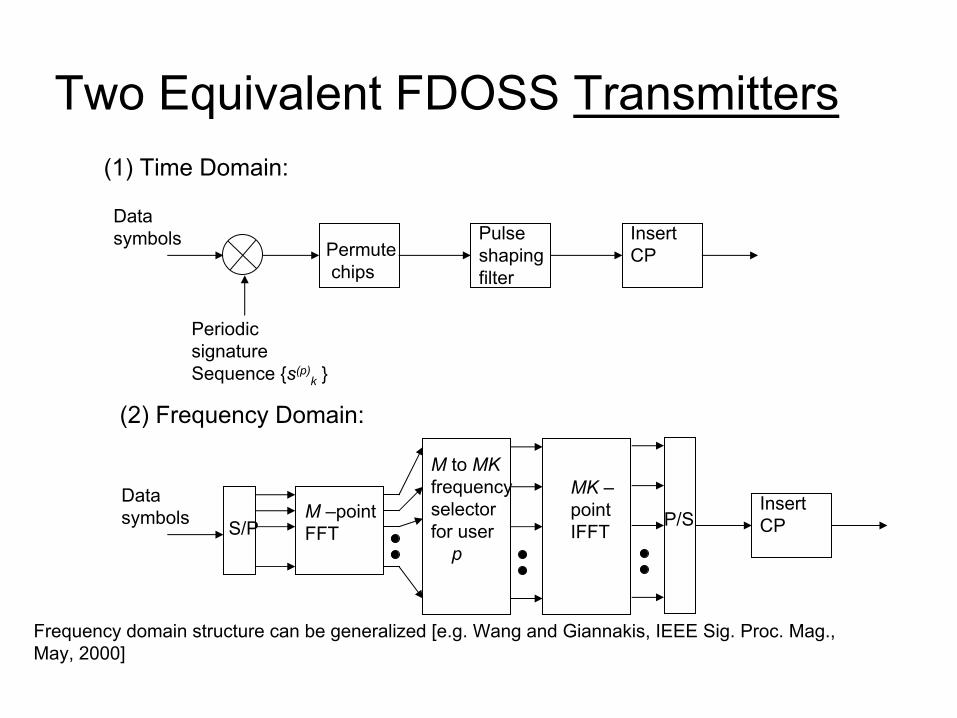
Two Equivalent FDOSS Transmitters
Datasymbols
(1) Time Domain:
Periodicsignature Sequence {s(p)
k }
Permutechips
Pulseshapingfilter
InsertCP
(2) Frequency Domain:
Datasymbols S/P
M –pointFFT
MK –pointIFFT P/S
InsertCP
M to MKfrequencyselectorfor user
p
Frequency domain structure can be generalized [e.g. Wang and Giannakis, IEEE Sig. Proc. Mag., May, 2000]