Embed Size (px)
Citation preview
PhotoelectricSensors
BFB/BOSFiber Optic Base Units
2.2.2
When there’s no spacefor a photoelectric sensor,there is only one solution:user fiber optics!
If there are no particulardemands for toughness anambient temperature orchemical resistance, thenplastic fiber optics are theright choice.
A wide range of specialbase units with variousperformance and functionfeatures is available whenusing the fiber optics.From the simple versionwith potentiometer to thehigh-end unit with display.
Applications
– Small parts detection– Suitable for tight mounting
conditions– Inspecting parts features– Counting (e.g. counting
drops)– Precise parts positioning– Assembly and handling– Robotics
BOS 74K...
BOS 6K...
BOS 18KF...
BOS 73K...
BFB 75K...
BFB/BOSFiber Optic Base UnitsProduct Overview
2.2.3
2.2
Connectors ...page 5.2 ...
2.3
5
PhotoelectricSensors
Photoelectricsensorsaccessoriespage 2.3.2 ...
Type
Fiber opticbase units
BFB 75K-001-P-S75BFB 75K-001-N-S75BFB 75K-001-P-02BFB 75K-001-N-02
BFB 75K-002-P-S75BFB 75K-002-N-S75
BFB 75K-003-P-02BFB 75K-003-N-02
BOS 73K-PU-1FR-C-02BOS 73K-PU-1FR-C-S75-00,1
BOS 74K-UU-1FR-B0-Z-S49-00,2BOS 74K-UU-1FR-B0-Z-02BOS 74K-UU-1FS-B0-Z-02
BOS 6K-PU-1FR-S75-CBOS 6K-PU-1FR-C-02BOS 6K-NU-1FR-S75-CBOS 6K-NU-1FR-C-02
BOS 18KF-PA-1FR-S4-CBOS 18KF-PA-1FR-C-02BOS 18KF-NA-1FR-S4-CBOS 18KF-NA-1FR-C-02
OutputLighttype
Connection
1.5 kHz1.5 kHz1.5 kHz1.5 kHz
8 kHz8 kHz
8 kHz8 kHz
1 kHz1 kHz
1 kHz1 kHz8 kHz
1 kHz1 kHz1 kHz1 kHz
1 kHz1 kHz1 kHz1 kHz
Outputfunction
Page
2.2.52.2.52.2.52.2.5
2.2.72.2.7
2.2.72.2.7
2.2.92.2.9
2.2.112.2.112.2.11
2.2.132.2.132.2.132.2.13
2.2.152.2.152.2.152.2.15
Specialfeatures
UBSwitchingfrequency
Fiber Optic Base Units
www.balluff.com
Red
ligh
t
M8
conn
ecto
r, 3-
pin
Cab
le
10...
30 V
DC
Teac
h-in
NP
N-T
rans
isto
r
PN
P-T
rans
isto
r
Ligh
t-on
Dar
k-on
Ala
rm o
utpu
t
11...
26 V
DC
M8
conn
ecto
r, 4-
pin
Dis
play
M12
con
nect
or, 4
-pin
Ana
log
outp
ut
BFB 75KFiber Optic Base Units
2.2.4
Recommendedaccessoriesplease order separately
ConnectorBKS-S 74/BKS-S 75
Mounting notes for fiber opticsThe resistance of the sealing ring must be overcome whenconnecting the fiber optics to the base unit.
Wiring diagrams
BFB 75K-001-P
BFB 75K-001-N
Control panel
Operatingvoltageindicator
Switchingstateindicator
Teach key
The BFB 75K-001…is considered the basic modelof the new series of fiberoptic base units BFB 75K forDIN rail mount.As an economical sensor itis ideally suited for standardapplications.Ease of setting using ateach-in procedure on thesensor or via an externalteach line make the sensorespecially user-friendly.
Features
– Red light– Teach-in– Connector and cable
versions
PhotoelectricSensors
2.2.5
BFB 75KFiber Optic Base Units
2.2
Photoelectricsensorsaccessoriespage 2.3.2 ...
2.3
SeriesPlastic fiber optic base unit
Sensing distance/range
Base unitPNPNPNElectrical dataSupply voltage UB
RippleNo-load supply current I0 max.Switching outputSwitching typeOutput currentVoltage drop Ud at IeSettingsOptical dataEmitter, light typeWavelengthLight spot diameterTime dataResponse timeSwitching frequency fIndicatorsPower-on indicatorSwitching state indicatorMechanical dataConnectionNo. of wires × cross-sectionHousing materialOptical surfaceWeightAmbient dataDegree of protection per IEC 60529Polarity reversal protectedShort circuit protectedAmbient temperature range Ta
Fiber Optic Base Units
www.balluff.com
BFB 75Kfor plastic fiber optics
with outside diameter 2.2 mmdepends on fiber optics
BFB 75K-001-P-02BFB 75K-001-N-02
10...30 V DC≤ 10 %
≤ 20 mAPNP- or NPN-Transistor
Light-/dark-on (selectable)100 mA≤ 1.5 VTeach-in
LED, red light660 nm
depends on fiber optics
1.5 kHz
LED greenLED yellow
2 m cable, PVC4×0.14 mm2
ABSdepends on fiber optic cable
50 g
IP 64yesyes
–20...+60 °C
BFB 75Kfor plastic fiber optics
with outside diameter 2.2 mmdepends on fiber optic cable
BFB 75K-001-P-S75BFB 75K-001-N-S75
10...30 V DC≤ 10 %
≤ 20 mAPNP- or NPN-Transistor
Light-/dark-on (selectable)100 mA≤ 1.5 VTeach-in
LED, red light660 nm
depends on fiber optics
1.5 kHz
LED greenLED yellow
M8 connector, 4-pin
ABSdepends on fiber optic cable
20 g
IP 64yesyes
–20...+60 °C
Connector orientationConnectors ...page 5.2 ...
5
Diff
use
Diff
use
LED
LED
PhotoelectricSensors
BFB 75KFiber Optic Base Units
2.2.6
Recommendedaccessoriesplease order separately
ConnectorBKS-S 74/BKS-S 75
Wiring diagrams
Control panel
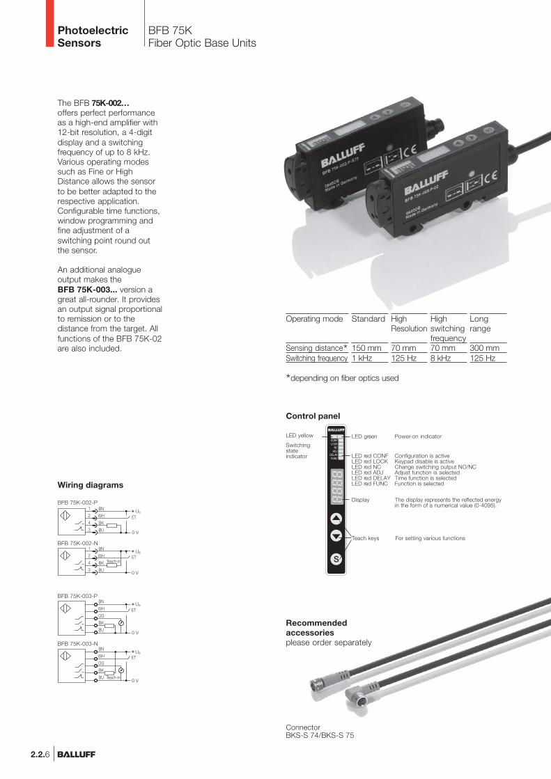
The BFB 75K-002…offers perfect performanceas a high-end amplifier with12-bit resolution, a 4-digitdisplay and a switchingfrequency of up to 8 kHz.Various operating modessuch as Fine or HighDistance allows the sensorto be better adapted to therespective application.Configurable time functions,window programming andfine adjustment of aswitching point round outthe sensor.
An additional analogueoutput makes theBFB 75K-003... version agreat all-rounder. It providesan output signal proportionalto remission or to thedistance from the target. Allfunctions of the BFB 75K-02are also included.
*depending on fiber optics used
Operating mode
Sensing distance*Switching frequency
Standard
150 mm1 kHz
HighResolution
70 mm125 Hz
Highswitchingfrequency70 mm8 kHz
Longrange
300 mm125 Hz
LED green Power-on indicator
LED red CONF Configuration is activeLED red LOCK Keypad disable is activeLED red NC Change switching output NO/NCLED red ADJ Adjust function is selectedLED red DELAY Time function is selectedLED red FUNC Function is selected
Display The display represents the reflected energyin the form of a numerical value (0-4095).
Teach keys For setting various functions
LED yellow
Switchingstateindicator
BFB 75K-003-P
BFB 75K-003-N
BFB 75K-002-P
BFB 75K-002-N
PhotoelectricSensors
2.2.7
BFB 75KFiber Optic Base Units
2.2
Photoelectricsensorsaccessoriespage 2.3.2 ...
2.3
SeriesPlastic fiber optic base unit
Sensing distance/range
Base unitPNPNPNElectrical dataSupply voltage UB
RippleNo-load supply current I0 max.Analog outputSwitching outputSwitching typeOutput currentVoltage drop Ud at IeSettingsOptical dataEmitter, light typeWavelengthLight spot diameterTime dataSwitching frequency f Standard
Fast ModeTime function
IndicatorsPower-on indicatorSwitching state indicatorStatus indicatorDisplayMechanical dataConnectionNo. of wires × cross-sectionHousing materialOptical surfaceWeightAmbient dataDegree of protection per IEC 60529Polarity reversal protectedShort circuit protectedAmbient temperature range Ta
Fiber Optic Base Units
www.balluff.com
Connectors ...page 5.2 ...
5
But
tons
But
tons
LED
LED
Dis
pla
y
Dis
pla
y
�
BFB 75Kfor plastic fiber optics
with outside diameter 2.2 mmdepends on fiber optics
BFB 75K-003-P-02BFB 75K-003-N-02
10...30 V DC≤ 10 %
≤ 25 mA0...10 V (max. 2 mA)
PNP- or NPN-TransistorLight-/dark-on (selectable)
100 mA≤ 2 V
Teach-in
LED, red light630 nm
depends on fiber optics
1 kHz8 kHz
On- and/or off-delay1...2000 ms adjustable
LED greenLED yellow6× LED red
4-digit
2 m cable, PVC5×0.14 mm2
ABSdepends on fiber optic cable
50 g
IP 64yesyes
–20...+60 °C
BFB 75Kfor plastic fiber optics
with outside diameter 2.2 mmdepends on fiber optics
BFB 75K-002-P-S75BFB 75K-002-N-S75
10...30 V DC≤ 10 %
≤ 25 mA
PNP- or NPN-TransistorLight-/dark-on (selectable)
100 mA≤ 2 V
Teach-in
LED, red light630 nm
depends on fiber optics
1 kHz8 kHz
On- and/or off-delay1...2000 ms adjustable
LED greenLED yellow6× LED red
4-digit
M8 connector, 4-pin
ABSdepends on fiber optic cable
20 g
IP 64yesyes
–20...+60 °C
PhotoelectricSensors
BOS 73KFiber Optic Base Units
2.2.8
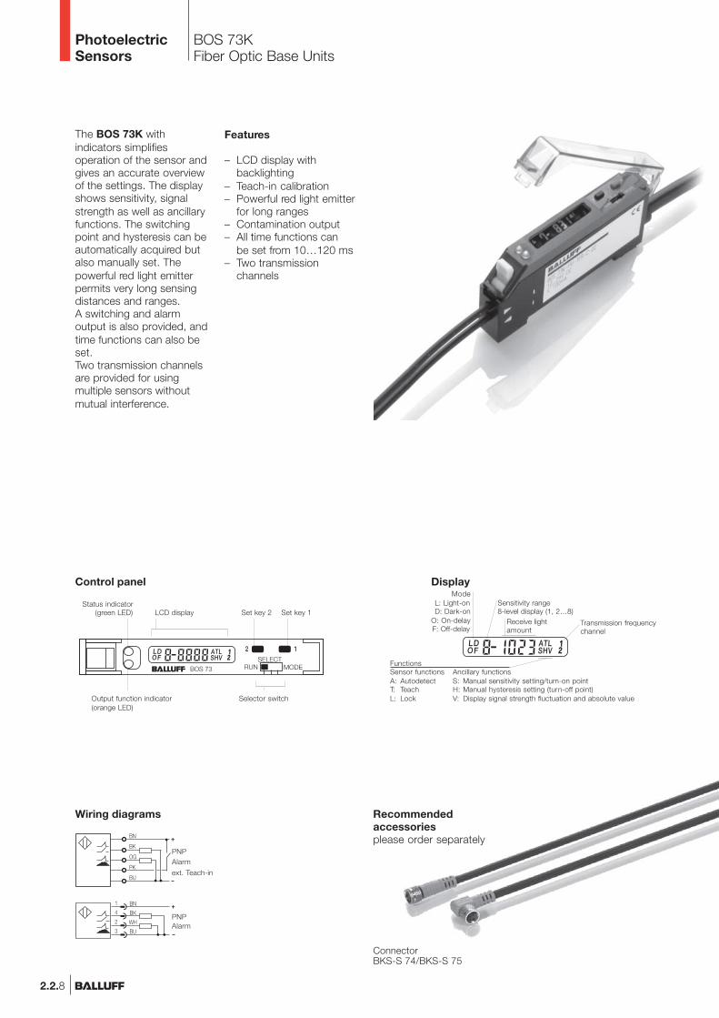
The BOS 73K withindicators simplifiesoperation of the sensor andgives an accurate overviewof the settings. The displayshows sensitivity, signalstrength as well as ancillaryfunctions. The switchingpoint and hysteresis can beautomatically acquired butalso manually set. Thepowerful red light emitterpermits very long sensingdistances and ranges.A switching and alarmoutput is also provided, andtime functions can also beset.Two transmission channelsare provided for usingmultiple sensors withoutmutual interference.
Features
– LCD display withbacklighting
– Teach-in calibration– Powerful red light emitter
for long ranges– Contamination output– All time functions can
be set from 10…120 ms– Two transmission
channels
Recommendedaccessoriesplease order separately
ConnectorBKS-S 74/BKS-S 75
Control panel
Wiring diagrams
ModeL: Light-onD: Dark-on
O: On-delayF: Off-delay
Display
Sensitivity range8-level display (1, 2…8)
Receive lightamount
Transmission frequencychannel
FunctionsSensor functions Ancillary functionsA: Autodetect S: Manual sensitivity setting/turn-on pointT: Teach H: Manual hysteresis setting (turn-off point)L: Lock V: Display signal strength fluctuation and absolute value
Status indicator(green LED) LCD display Set key 2 Set key 1
Output function indicator(orange LED)
Selector switch
PNPAlarm
ext. Teach-in
AlarmPNP
PhotoelectricSensors
2.2.9
BOS 73KFiber Optic Base Units
2.2
Photoelectricsensorsaccessoriespage 2.3.2 ...
2.3
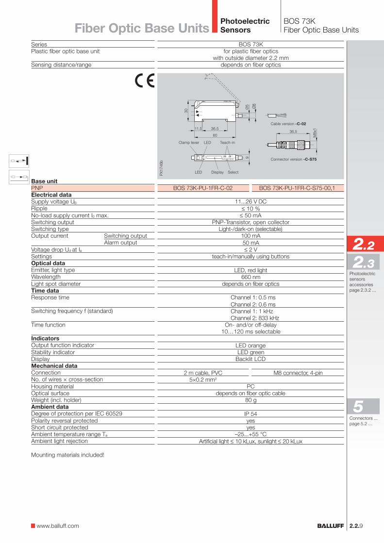
BOS 73Kfor plastic fiber optics
with outside diameter 2.2 mmdepends on fiber optics
SeriesPlastic fiber optic base unit
Sensing distance/range
Base unitPNPElectrical dataSupply voltage UB
RippleNo-load supply current I0 max.Switching outputSwitching typeOutput current Switching output
Alarm outputVoltage drop Ud at IeSettingsOptical dataEmitter, light typeWavelengthLight spot diameterTime dataResponse time
Switching frequency f (standard)
Time function
IndicatorsOutput function indicatorStability indicatorDisplayMechanical dataConnectionNo. of wires × cross-sectionHousing materialOptical surfaceWeight (incl. holder)Ambient dataDegree of protection per IEC 60529Polarity reversal protectedShort circuit protectedAmbient temperature range Ta
Ambient light rejection
Mounting materials included!
BOS 73K-PU-1FR-C-02 BOS 73K-PU-1FR-C-S75-00,1
11...26 V DC≤ 10 %
≤ 50 mAPNP-Transistor, open collector
Light-/dark-on (selectable)100 mA50 mA≤ 2 V
teach-in/manually using buttons
LED, red light660 nm
depends on fiber optics
Channel 1: 0.5 msChannel 2: 0.6 msChannel 1: 1 kHzChannel 2: 833 kHz
On- and/or off-delay10…120 ms selectable
LED orangeLED green
Backlit LCD
2 m cable, PVC M8 connector, 4-pin5×0.2 mm2
PCdepends on fiber optic cable
80 g
IP 54yesyes
–25...+55 °CArtificial light ≤ 10 kLux, sunlight ≤ 20 kLux
Display Select
Clamp lever Teach-inLED
LED
Connector version -C-S75
Cable version -C-02
Fiber Optic Base Units
www.balluff.com
Connectors ...page 5.2 ...
5
PhotoelectricSensors
2.2.10
PhotoelectricSensors
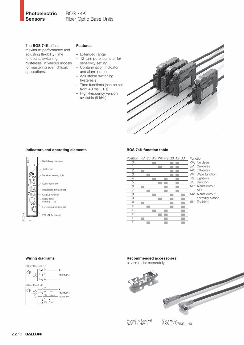
The BOS 74K offersmaximum performance andadjusting flexibility (timefunctions, switchinghysteresis) in various modelsfor mastering even difficultapplications.
Features
– Extended range– 12-turn potentiometer for
sensitivity setting– Contamination indicator
and alarm output– Adjustable switching
hysteresis– Time functions (can be set
from 40 ms…1 s)– High-frequency version
available (8 kHz)
Recommended accessoriesplease order separately
ConnectorBKS-_ 48/BKS-_ 49
Mounting bracketBOS 74-HW-1
Indicators and operating elements
Switching distance
Hysteresis
Receiver seeing light
Calibration aid
Response time select
Output function
Delay time(40 ms…1 s)
Function and time set
PNP/NPN switch
Position KV EV AV WF HS DS AE AA0123456789ABCDEF
FunctionKV: No delayEV: On-delayAV: Off-delayWF: Wipe functionHS: Light-onDS: Dark-onAE: Alarm output
NOAA: Alarm output
normally closed: Enabled
BOS 74K function table
Wiring diagrams
+++++
–––––
PNP/NPN
+++++
–––––
PNP/NPNPNP/NPN
BOS 74K...Z-02
BOS 74K...S49-0,2
BOS 74KFiber Optic Base Units
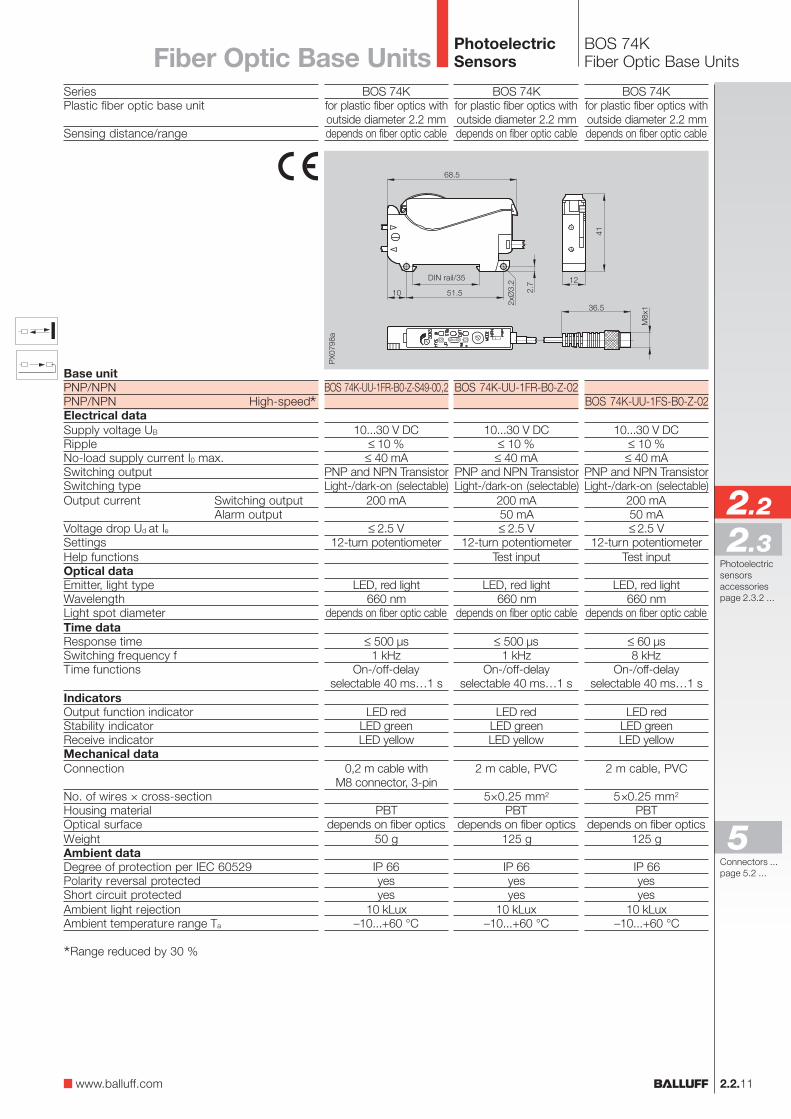
BOS 74KFiber Optic Base Units
2.2.11
SeriesPlastic fiber optic base unit
Sensing distance/range
Base unitPNP/NPNPNP/NPN High-speed*Electrical dataSupply voltage UB
RippleNo-load supply current I0 max.Switching outputSwitching typeOutput current Switching output
Alarm outputVoltage drop Ud at IeSettingsHelp functionsOptical dataEmitter, light typeWavelengthLight spot diameterTime dataResponse timeSwitching frequency fTime functions
IndicatorsOutput function indicatorStability indicatorReceive indicatorMechanical dataConnection
No. of wires × cross-sectionHousing materialOptical surfaceWeightAmbient dataDegree of protection per IEC 60529Polarity reversal protectedShort circuit protectedAmbient light rejectionAmbient temperature range Ta
*Range reduced by 30 %
DIN rail/35
BOS 74Kfor plastic fiber optics withoutside diameter 2.2 mmdepends on fiber optic cable
BOS 74K-UU-1FR-B0-Z-S49-00,2
10...30 V DC≤ 10 %
≤ 40 mAPNP and NPN TransistorLight-/dark-on (selectable)
200 mA
≤ 2.5 V12-turn potentiometer
LED, red light660 nm
depends on fiber optic cable
≤ 500 µs1 kHz
On-/off-delayselectable 40 ms…1 s
LED redLED greenLED yellow
0,2 m cable withM8 connector, 3-pin
PBTdepends on fiber optics
50 g
IP 66yesyes
10 kLux–10...+60 °C
2.2
Photoelectricsensorsaccessoriespage 2.3.2 ...
2.3
PhotoelectricSensorsFiber Optic Base Units
BOS 74Kfor plastic fiber optics withoutside diameter 2.2 mmdepends on fiber optic cable
BOS 74K-UU-1FR-B0-Z-02
10...30 V DC≤ 10 %
≤ 40 mAPNP and NPN TransistorLight-/dark-on (selectable)
200 mA50 mA≤ 2.5 V
12-turn potentiometerTest input
LED, red light660 nm
depends on fiber optic cable
≤ 500 µs1 kHz
On-/off-delayselectable 40 ms…1 s
LED redLED greenLED yellow
2 m cable, PVC
5×0.25 mm2
PBTdepends on fiber optics
125 g
IP 66yesyes
10 kLux–10...+60 °C
BOS 74Kfor plastic fiber optics withoutside diameter 2.2 mmdepends on fiber optic cable
BOS 74K-UU-1FS-B0-Z-02
10...30 V DC≤ 10 %
≤ 40 mAPNP and NPN TransistorLight-/dark-on (selectable)
200 mA50 mA≤ 2.5 V
12-turn potentiometerTest input
LED, red light660 nm
depends on fiber optic cable
≤ 60 µs8 kHz
On-/off-delayselectable 40 ms…1 s
LED redLED greenLED yellow
2 m cable, PVC
5×0.25 mm2
PBTdepends on fiber optics
125 g
IP 66yesyes
10 kLux–10...+60 °C
www.balluff.com
Connectors ...page 5.2 ...
5
2.2.12
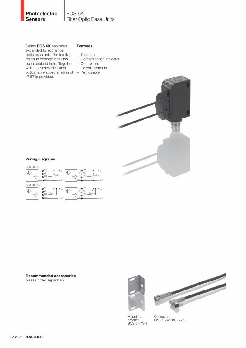
PhotoelectricSensors
Series BOS 6K has beenexpanded to add a fiberoptic base unit. The familiarteach-in concept has alsobeen retained here. Togetherwith the Series BFO fiberoptics, an enclosure rating ofIP 67 is provided.
Recommended accessoriesplease order separately
Wiring diagrams
ConnectorBKS-S 74/BKS-S 75
MountingbracketBOS 6-HW-1
BOS 6K-PU-...
BOS 6K-NU-...
BOS 6KFiber Optic Base Units
Features
– Teach-in– Contamination indicator– Control line
for ext. Teach-in– Key disable
BOS 6KFiber Optic Base Units
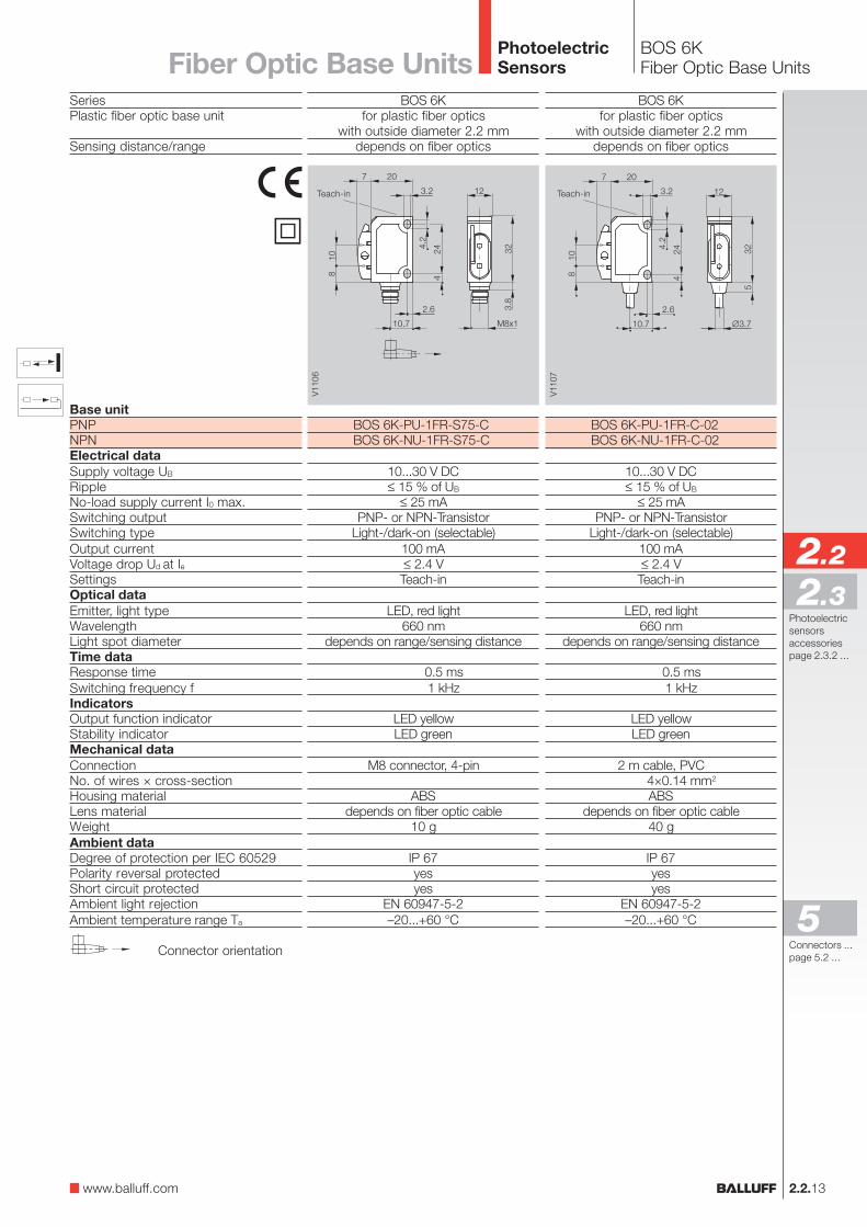
2.2.13
2.2
Photoelectricsensorsaccessoriespage 2.3.2 ...
2.3
PhotoelectricSensorsFiber Optic Base Units
SeriesPlastic fiber optic base unit
Sensing distance/range
Base unitPNPNPNElectrical dataSupply voltage UB
RippleNo-load supply current I0 max.Switching outputSwitching typeOutput currentVoltage drop Ud at IeSettingsOptical dataEmitter, light typeWavelengthLight spot diameterTime dataResponse timeSwitching frequency fIndicatorsOutput function indicatorStability indicatorMechanical dataConnectionNo. of wires × cross-sectionHousing materialLens materialWeightAmbient dataDegree of protection per IEC 60529Polarity reversal protectedShort circuit protectedAmbient light rejectionAmbient temperature range Ta
BOS 6Kfor plastic fiber optics
with outside diameter 2.2 mmdepends on fiber optics
BOS 6K-PU-1FR-S75-CBOS 6K-NU-1FR-S75-C
10...30 V DC≤ 15 % of UB
≤ 25 mAPNP- or NPN-Transistor
Light-/dark-on (selectable)100 mA≤ 2.4 VTeach-in
LED, red light660 nm
depends on range/sensing distance
0.5 ms1 kHz
LED yellowLED green
M8 connector, 4-pin
ABSdepends on fiber optic cable
10 g
IP 67yesyes
EN 60947-5-2–20...+60 °C
BOS 6Kfor plastic fiber optics
with outside diameter 2.2 mmdepends on fiber optics
BOS 6K-PU-1FR-C-02BOS 6K-NU-1FR-C-02
10...30 V DC≤ 15 % of UB
≤ 25 mAPNP- or NPN-Transistor
Light-/dark-on (selectable)100 mA≤ 2.4 VTeach-in
LED, red light660 nm
depends on range/sensing distance
0.5 ms1 kHz
LED yellowLED green
2 m cable, PVC4×0.14 mm2
ABSdepends on fiber optic cable
40 g
IP 67yesyes
EN 60947-5-2–20...+60 °C
www.balluff.com
Connector orientation
�
Teach-in Teach-in
Connectors ...page 5.2 ...
5
2.2.14
PhotoelectricSensors
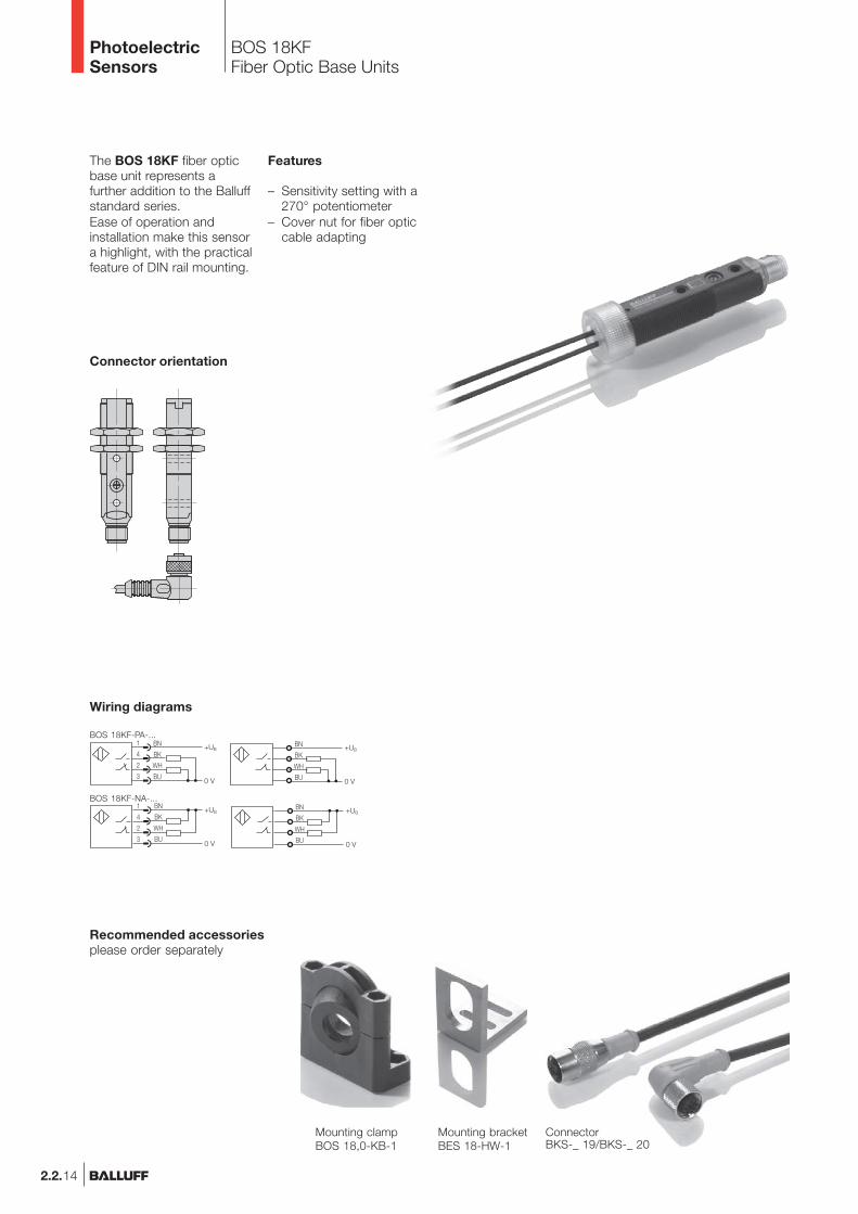
The BOS 18KF fiber opticbase unit represents afurther addition to the Balluffstandard series.Ease of operation andinstallation make this sensora highlight, with the practicalfeature of DIN rail mounting.
Features
– Sensitivity setting with a270° potentiometer
– Cover nut for fiber opticcable adapting
Connector orientation
Mounting clampBOS 18,0-KB-1
Mounting bracketBES 18-HW-1
ConnectorBKS-_ 19/BKS-_ 20
Recommended accessoriesplease order separately
Wiring diagrams
BN
BK
WH
BU
+UB
0 V
BN
BK
WH
BU
+UB
0 V
BOS 18KF-PA-...
BOS 18KF-NA-...
BOS 18KFFiber Optic Base Units
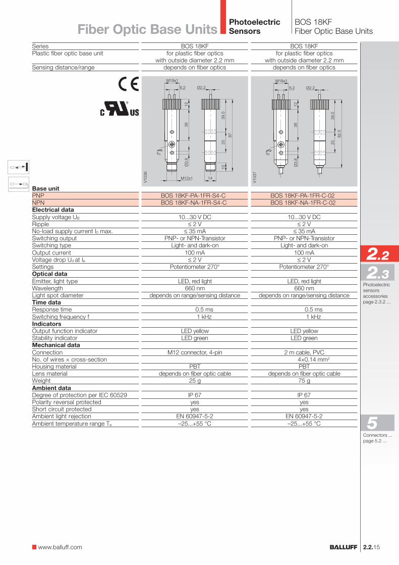
SeriesPlastic fiber optic base unit
Sensing distance/range
Base unitPNPNPNElectrical dataSupply voltage UB
RippleNo-load supply current I0 max.Switching outputSwitching typeOutput currentVoltage drop Ud at IeSettingsOptical dataEmitter, light typeWavelengthLight spot diameterTime dataResponse timeSwitching frequency fIndicatorsOutput function indicatorStability indicatorMechanical dataConnectionNo. of wires × cross-sectionHousing materialLens materialWeightAmbient dataDegree of protection per IEC 60529Polarity reversal protectedShort circuit protectedAmbient light rejectionAmbient temperature range Ta
BOS 18KFFiber Optic Base Units
2.2.15
2.2
Photoelectricsensorsaccessoriespage 2.3.2 ...
2.3
PhotoelectricSensorsFiber Optic Base Units
BOS 18KFfor plastic fiber optics
with outside diameter 2.2 mmdepends on fiber optics
BOS 18KF-PA-1FR-S4-CBOS 18KF-NA-1FR-S4-C
10...30 V DC≤ 2 V
≤ 35 mAPNP- or NPN-Transistor
Light- and dark-on100 mA
≤ 2 VPotentiometer 270°
LED, red light660 nm
depends on range/sensing distance
0.5 ms1 kHz
LED yellowLED green
M12 connector, 4-pin
PBTdepends on fiber optic cable
25 g
IP 67yesyes
EN 60947-5-2–25...+55 °C
BOS 18KFfor plastic fiber optics
with outside diameter 2.2 mmdepends on fiber optics
BOS 18KF-PA-1FR-C-02BOS 18KF-NA-1FR-C-02
10...30 V DC≤ 2 V
≤ 35 mAPNP- or NPN-Transistor
Light- and dark-on100 mA
≤ 2 VPotentiometer 270°
LED, red light660 nm
depends on range/sensing distance
0.5 ms1 kHz
LED yellowLED green
2 m cable, PVC4×0.14 mm2
PBTdepends on fiber optic cable
75 g
IP 67yesyes
EN 60947-5-2–25...+55 °C
www.balluff.com
Connectors ...page 5.2 ...
5