Embed Size (px)
Citation preview

BIONIC HAND
GRADUATION PROJECT
BME-402
Murat Emre Bayramoğlu
Kaan Tol
Mansoor Hayat Malik
Nicosia-2014

1
Abstract
The idea of this Project comes from the Nuclear medicine and microbiology of
hospitals where the staff is always exposed to life threatening conditions. It can be improved
to reduce labour costs and Provide a safer working environment in health sector or various
other sectors.This Project will enable staff to contınue routine Works without being exposed
to danger.
The Project consist of two parts consisting of sender and reciever.The sender part
consist of a gloove with flex sensors embeded on its top.The user will be wearing the gloove
and signals taken from the flex sensor will be transmitted wirelessly to the reciever part.The
reciever part will take the signals and operate the servo motors with the help of these signals
controlled by microprocessors.
The Project can be further improved in future with the addition of EMG signal
operating arm leading to the creation of a bionic arm.It can also be used in Nuclear
medicine for filling the doses of radioactive materials.In the end,It can be used in
microbiology to perform experiments.

2
Table Of Contents A. CONTROL GLOVE ............................................................................................................................. 4
1. Flex Sensor ................................................................................................................................... 4
Summary ............................................................................................................................................. 4
Conductive Ink-based .......................................................................................................................... 4
Properties ......................................................................................................................................... 5
Applications ..................................................................................................................................... 6
Fiber-optic ........................................................................................................................................... 6
Properties ......................................................................................................................................... 6
Applications ..................................................................................................................................... 7
Conductive Fabric/Thread/Polymer-based .......................................................................................... 7
2. Arduino ........................................................................................................................................ 8
Overview ......................................................................................................................................... 8
Summary ......................................................................................................................................... 9
Schematic & Reference Design ....................................................................................................... 9
Power ............................................................................................................................................... 9
Memory ......................................................................................................................................... 10
Input and Output ............................................................................................................................ 10
Communication ............................................................................................................................. 11
Programming ................................................................................................................................. 11
Automatic (Software) Reset .......................................................................................................... 12
USB Overcurrent Protection.......................................................................................................... 12
Physical Characteristics ................................................................................................................. 12
3. XBee Wireless Module .............................................................................................................. 13
Overview ....................................................................................................................................... 13
Jumper Settings ............................................................................................................................. 13
Networking .................................................................................................................................... 14
4. Circuit Diaghram ........................................................................................................................ 17
5. Materials .................................................................................................................................... 17
6. The Values ................................................................................................................................. 20
B. ARDUINO WIRELESS BIONIC HAND ............................................................................................... 23
1. Arduino User Guide ................................................................................................................... 23
1 | Get an Arduino board and USB cable ...................................................................................... 23
2 | Download the Arduino environment ........................................................................................ 23

3
3 | Connect the board ..................................................................................................................... 23
4 | Install the drivers ...................................................................................................................... 23
5 | Launch the Arduino application ............................................................................................... 24
6 | Open the blink example ............................................................................................................ 25
7 | Select your board ...................................................................................................................... 25
8 | Select your serial port ............................................................................................................... 26
9 | Upload the program .................................................................................................................. 26
2. XBee Wireless Module For Robotic Hand ................................................................................. 28
3. Servo Motors ............................................................................................................................. 28
4. Circuit Diaghram For Receiver Part ........................................................................................... 31
5. Code ........................................................................................................................................... 32
6. Materials For Bionic Part ........................................................................................................... 35
C. MATERIAL LIST ............................................................................................................................... 37
4
A. CONTROL GLOVE
1. Flex Sensor
Summary
Flexion sensors, (from Latin flectere, 'to bend') also called bend sensors, measure the
amount of deflection caused by bending the sensor. There are various ways of sensing
deflection, from strain-gaugesto hall-effect sensors. The three most common types of flexion
sensors are:
conductive ink-based
fibre-optic
conductive fabric/thread/polymer-based
A property of bend sensors worth noting is that bending the sensor at one point to a prescribed
angle is not the most effective use of the sensor. As well, bending the sensor at one point to
more than 90˚ may permanently damage the sensor. Instead, bend the sensor around a radius
of curvature. The smaller the radius of curvature and the more the whole length of the sensor
is involved in the deflection, the greater the resistance will be (which will be much greater
than the resistance achieved if the sensor is fixed at one end and bent sharply to a high
degree). In fact, Infusion Systems define the sensing parameter as “flex angle multiplied by
radius”.
Specifications
A typical bend sensor has the following basic specifications:
range of deflection
uni- vs. bi-directional sensing
uni- vs. bi-polar sensing
range of resistance (nominal to full-deflection)
Range of deflection: Determines the maximum angle of deflection that can be measured (as
opposed to the maximum angle the sensor can be bent).
Uni- vs. bi-directional sensing: Some flexion sensors increase the resistance when bent in
either of two opposing directions, however there is no difference in the measurement with
respect to the direction.
Uni- vs. bi-polar sensing: A bi-polar flexion sensor measures deflection in two opposing
directions yielding different measurements.
Range of resistance: Bend sensors can vary largely (even the same product) in terms of their
range of resistance, measured as the difference from nominal resistance to resistance at full
deflection.
Conductive Ink-based
These types of bend sensors are passive resistive devices typically fabricated by laying a strip
of resistive ink on a flexible plastic substrate, shaped as a thin, flexible stripe in lengths
between 1” and 5”. At rest (when laid flat), the bend sensor is characterized by an intrinsic
resistance. As the sensor is bent, the resistive materials inside it are pulled further apart.
Fewer adjacent resistive particles come into contact, thereby increasing the resistance.
5
Typically, the nominal resistance lays between 10kΩ and 50kΩ and increases by a factor of
10 at full deflection.
Within the layers of the flex sensor substrate is a printed pattern of conductive ink. To
conduct electricity, this ink contains carbon, or silver, particles mixed into a pigmented
medium. Typically, the carbon particles are suspended in the ink to avoid fading of the
pigment over time. This type of ink can also be safely applied to paper to avoid absorption
into the fibers, thus changing the paper’s properties. However, the carbon particles may be
sensitive to changes in humidity that can lead to smudging of the ink
Most conductive ink-based bend sensors on the market are unipolar devices, that is the
resistance increases as the deflection increases in one direction, and is unchanged if bent in
the other direction. Placing two devices back-to-back will allow bipolar measurements for
capturing deflections in both directions. Hysteresis and noise in resistance value are small if
not entirely negligible.
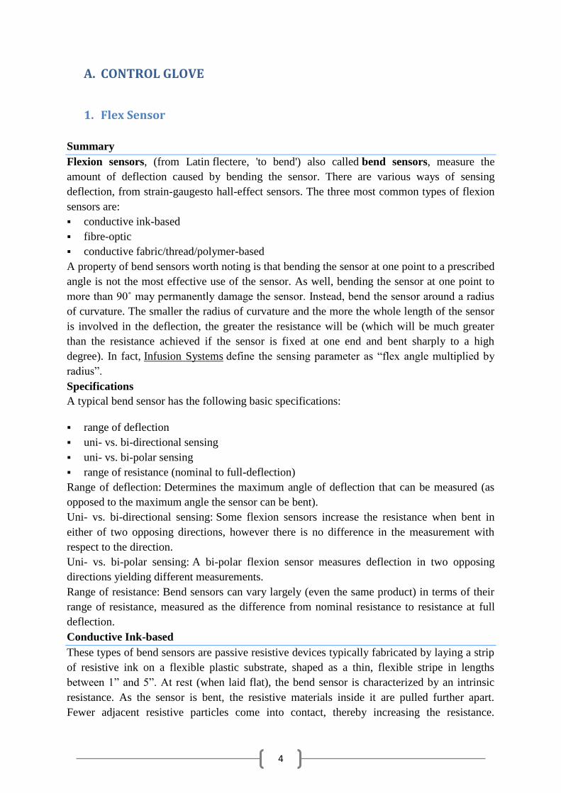
Flexpoint Sensor Systems Inc. makes the Bend Sensor® in 1”, 2”, and 3” lengths.
They are available with connectors that can be interfaced with standard sized
headers.
As length increases, the intrinsic resistance goes up, as does the resistance for
each sensor at full deflection. As well, there are different lamination and coating
options to increase durability and stiffness. For mechanical and electrical design
guides, refer to these links: mechanical specs and electronic specs.
Images Scientific Instruments offers the bipolar flexion sensor FLX-02, which
increases resistance in one direction and decreases resistance in the other
direction. In addition, Images SI sells a special component-based flexion sensor which can
also be used as a pressure sensor. This sensing principle is identical to
conductive/thread/polymer-based sensing illustrated below. Worth mentioning is the online
tutorial on how to construct a bi-directional (not: bi-polar!) bend sensor using a stripe of
resistive material which is sandwiched between two copper clad laminates and sealed using
heat shrink tubing.
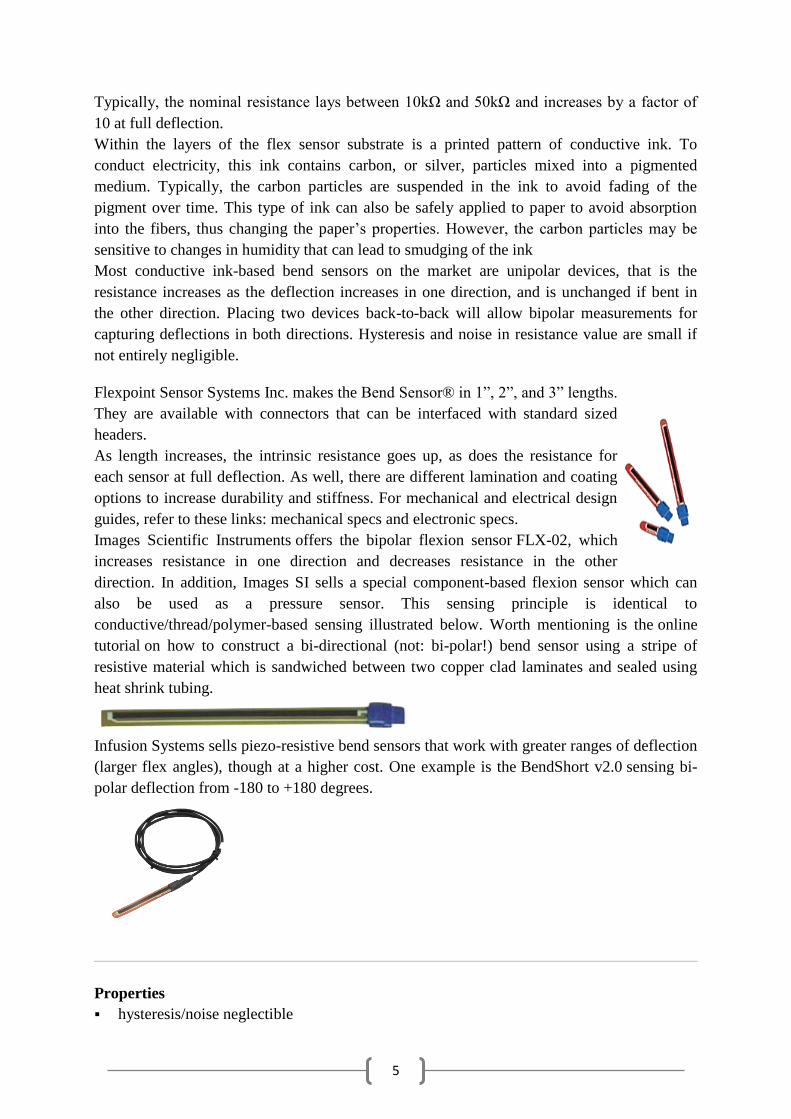
Infusion Systems sells piezo-resistive bend sensors that work with greater ranges of deflection
(larger flex angles), though at a higher cost. One example is the BendShort v2.0 sensing bi-
polar deflection from -180 to +180 degrees.
Properties
hysteresis/noise neglectible
6
resistance is function of radius of curvature, not angle at one point
high temperature and humidity-tolerance
relatively low cost
customizable (coatings, laminating materials)
Applications
automotive applications
industrial applications, e.g. safety switches, shipping, machine control
medical applications (e.g. “SmartBed”)
gaming devices
measuring devices
assistive technology
robotics
Fiber-optic
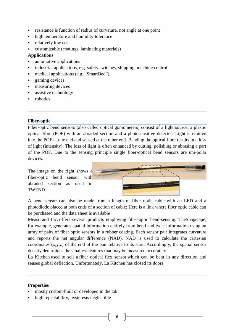
Fiber-optic bend sensors (also called optical goniometers) consist of a light source, a plastic
optical fibre (POF) with an abraded section and a photosensitive detector. Light is emitted
into the POF at one end and sensed at the other end. Bending the optical fibre results in a loss
of light (intensity). The loss of light is often enhanced by cutting, polishing or abrasing a part
of the POF. Due to the sensing principle single fiber-optical bend sensors are uni-polar
devices.
The image on the right shows a
fiber-optic bend sensor with
abraded section as used in
TWEND.
A bend sensor can also be made from a length of fiber optic cable with an LED and a
photodiode placed at both ends of a section of cable; Here is a link where fiber optic cable can
be purchased and the data sheet is available
Measurand Inc. offers several products employing fiber-optic bend-sensing. TheShapetape,
for example, generates spatial information entirely from bend and twist information using an
array of pairs of fiber optic sensors in a rubber coating. Each sensor pair integrates curvature
and reports the net angular difference (NAD). NAD is used to calculate the cartesian
coordinates (x,y,z) of the end of the pair relative to its start. Accordingly, the spatial sensor
density determines the smallest features that may be measured accurately.
La Kitchen used to sell a fiber optical flex sensor which can be bent in any direction and
senses global deflection. Unfortunately, La Kitchen has closed its doors.
Properties
mostly custom-built or developed in the lab
high repeatability, hysteresis neglectible
7
can be bent in any direction
usually unipolar measurement (global flexion)
can be expensive
Applications
medical applications
educational studies
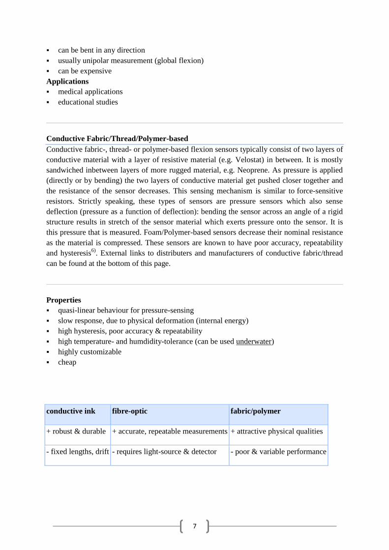
Conductive Fabric/Thread/Polymer-based
Conductive fabric-, thread- or polymer-based flexion sensors typically consist of two layers of
conductive material with a layer of resistive material (e.g. Velostat) in between. It is mostly
sandwiched inbetween layers of more rugged material, e.g. Neoprene. As pressure is applied
(directly or by bending) the two layers of conductive material get pushed closer together and
the resistance of the sensor decreases. This sensing mechanism is similar to force-sensitive
resistors. Strictly speaking, these types of sensors are pressure sensors which also sense
deflection (pressure as a function of deflection): bending the sensor across an angle of a rigid
structure results in stretch of the sensor material which exerts pressure onto the sensor. It is
this pressure that is measured. Foam/Polymer-based sensors decrease their nominal resistance
as the material is compressed. These sensors are known to have poor accuracy, repeatability
and hysteresis6)
. External links to distributers and manufacturers of conductive fabric/thread
can be found at the bottom of this page.
Properties
quasi-linear behaviour for pressure-sensing
slow response, due to physical deformation (internal energy)
high hysteresis, poor accuracy & repeatability
high temperature- and humdidity-tolerance (can be used underwater)
highly customizable
cheap
conductive ink fibre-optic fabric/polymer
+ robust & durable + accurate, repeatable measurements + attractive physical qualities
- fixed lengths, drift - requires light-source & detector - poor & variable performance
8
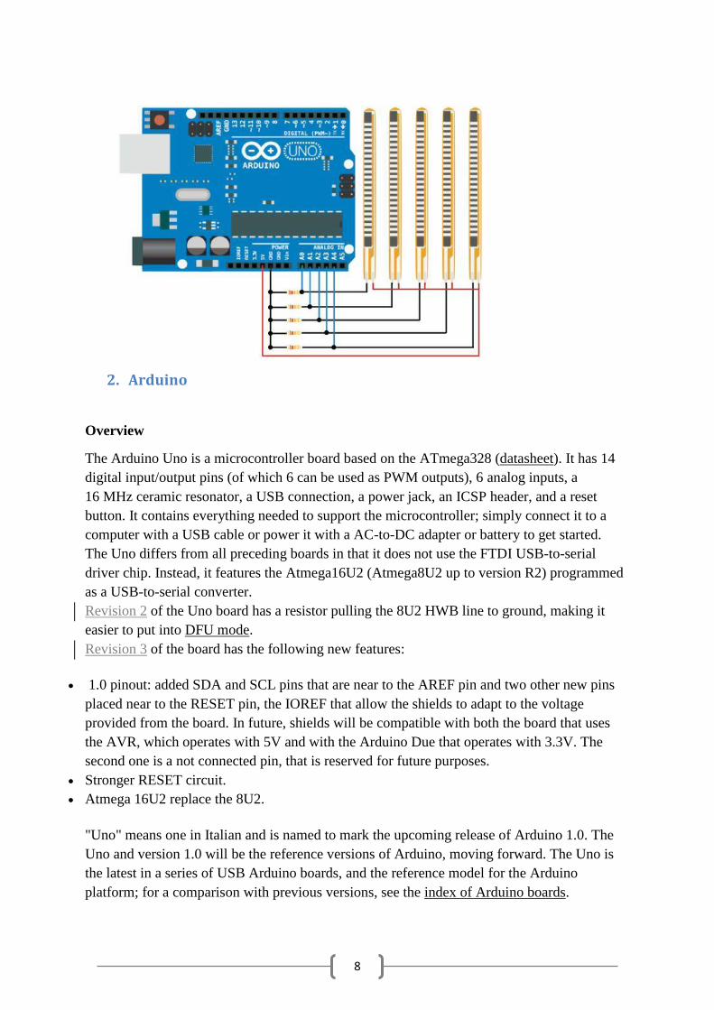
2. Arduino
Overview
The Arduino Uno is a microcontroller board based on the ATmega328 (datasheet). It has 14
digital input/output pins (of which 6 can be used as PWM outputs), 6 analog inputs, a
16 MHz ceramic resonator, a USB connection, a power jack, an ICSP header, and a reset
button. It contains everything needed to support the microcontroller; simply connect it to a
computer with a USB cable or power it with a AC-to-DC adapter or battery to get started.
The Uno differs from all preceding boards in that it does not use the FTDI USB-to-serial
driver chip. Instead, it features the Atmega16U2 (Atmega8U2 up to version R2) programmed
as a USB-to-serial converter.
Revision 2 of the Uno board has a resistor pulling the 8U2 HWB line to ground, making it
easier to put into DFU mode.
Revision 3 of the board has the following new features:
1.0 pinout: added SDA and SCL pins that are near to the AREF pin and two other new pins
placed near to the RESET pin, the IOREF that allow the shields to adapt to the voltage
provided from the board. In future, shields will be compatible with both the board that uses
the AVR, which operates with 5V and with the Arduino Due that operates with 3.3V. The
second one is a not connected pin, that is reserved for future purposes.
Stronger RESET circuit.
Atmega 16U2 replace the 8U2.
"Uno" means one in Italian and is named to mark the upcoming release of Arduino 1.0. The
Uno and version 1.0 will be the reference versions of Arduino, moving forward. The Uno is
the latest in a series of USB Arduino boards, and the reference model for the Arduino
platform; for a comparison with previous versions, see the index of Arduino boards.
9
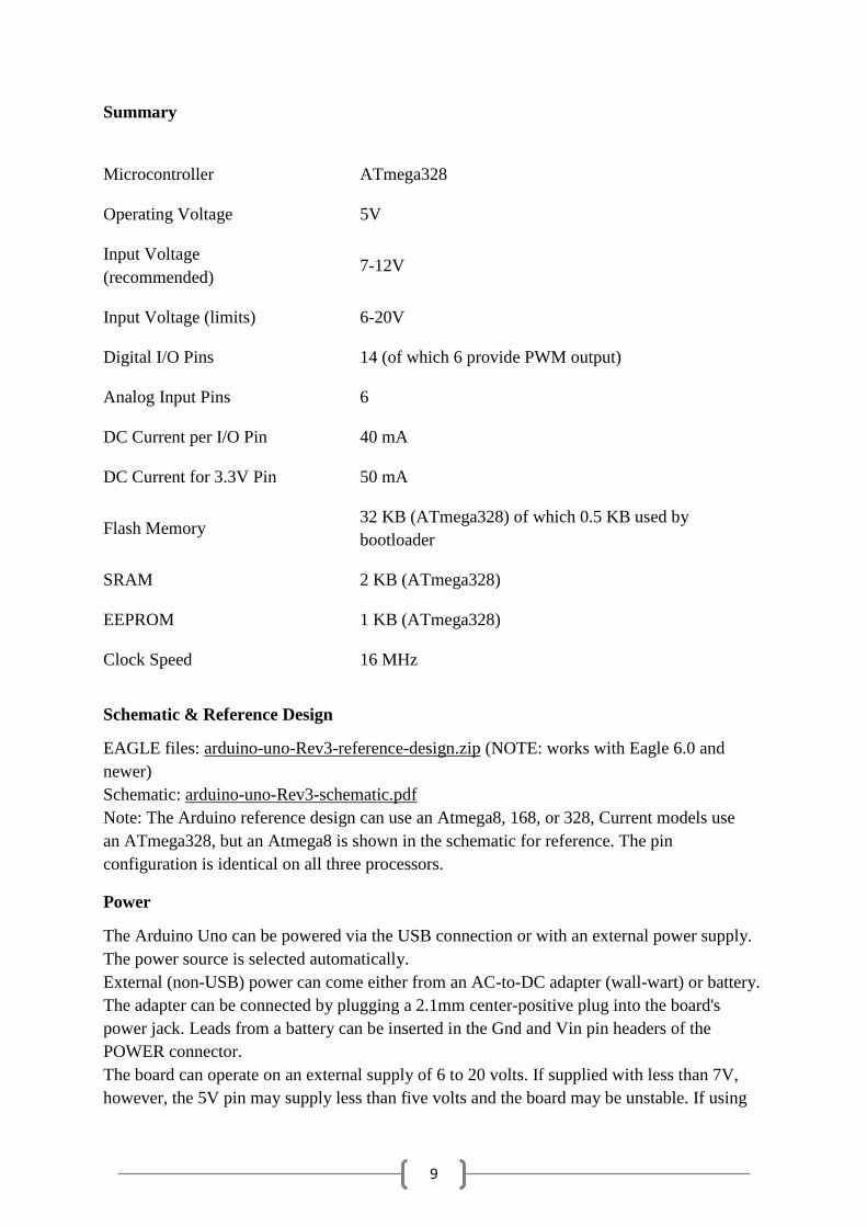
Summary
Microcontroller ATmega328
Operating Voltage 5V
Input Voltage
(recommended) 7-12V
Input Voltage (limits) 6-20V
Digital I/O Pins 14 (of which 6 provide PWM output)
Analog Input Pins 6
DC Current per I/O Pin 40 mA
DC Current for 3.3V Pin 50 mA
Flash Memory 32 KB (ATmega328) of which 0.5 KB used by
bootloader
SRAM 2 KB (ATmega328)
EEPROM 1 KB (ATmega328)
Clock Speed 16 MHz
Schematic & Reference Design
EAGLE files: arduino-uno-Rev3-reference-design.zip (NOTE: works with Eagle 6.0 and
newer)
Schematic: arduino-uno-Rev3-schematic.pdf
Note: The Arduino reference design can use an Atmega8, 168, or 328, Current models use
an ATmega328, but an Atmega8 is shown in the schematic for reference. The pin
configuration is identical on all three processors.
Power
The Arduino Uno can be powered via the USB connection or with an external power supply.
The power source is selected automatically.
External (non-USB) power can come either from an AC-to-DC adapter (wall-wart) or battery.
The adapter can be connected by plugging a 2.1mm center-positive plug into the board's
power jack. Leads from a battery can be inserted in the Gnd and Vin pin headers of the
POWER connector.
The board can operate on an external supply of 6 to 20 volts. If supplied with less than 7V,
however, the 5V pin may supply less than five volts and the board may be unstable. If using
10
more than 12V, the voltage regulator may overheat and damage the board. The recommended
range is 7 to 12 volts.
The power pins are as follows:
VIN. The input voltage to the Arduino board when it's using an external power source (as
opposed to 5 volts from the USB connection or other regulated power source). You can
supply voltage through this pin, or, if supplying voltage via the power jack, access it through
this pin.
5V.This pin outputs a regulated 5V from the regulator on the board. The board can be
supplied with power either from the DC power jack (7 - 12V), the USB connector (5V), or the
VIN pin of the board (7-12V). Supplying voltage via the 5V or 3.3V pins bypasses the
regulator, and can damage your board. We don't advise it.
3V3. A 3.3 volt supply generated by the on-board regulator. Maximum current draw is 50
mA.
GND. Ground pins.
IOREF. This pin on the Arduino board provides the voltage reference with which the
microcontroller operates. A properly configured shield can read the IOREF pin voltage and
select the appropriate power source or enable voltage translators on the outputs for working
with the 5V or 3.3V.
Memory
The ATmega328 has 32 KB (with 0.5 KB used for the bootloader). It also has 2 KB of SRAM
and 1 KB of EEPROM (which can be read and written with the EEPROM library).
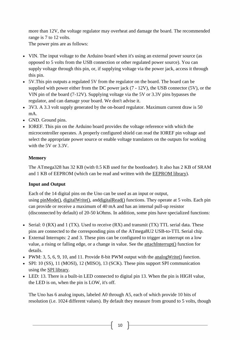
Input and Output
Each of the 14 digital pins on the Uno can be used as an input or output,
using pinMode(), digitalWrite(), anddigitalRead() functions. They operate at 5 volts. Each pin
can provide or receive a maximum of 40 mA and has an internal pull-up resistor
(disconnected by default) of 20-50 kOhms. In addition, some pins have specialized functions:
Serial: 0 (RX) and 1 (TX). Used to receive (RX) and transmit (TX) TTL serial data. These
pins are connected to the corresponding pins of the ATmega8U2 USB-to-TTL Serial chip.
External Interrupts: 2 and 3. These pins can be configured to trigger an interrupt on a low
value, a rising or falling edge, or a change in value. See the attachInterrupt() function for
details.
PWM: 3, 5, 6, 9, 10, and 11. Provide 8-bit PWM output with the analogWrite() function.
SPI: 10 (SS), 11 (MOSI), 12 (MISO), 13 (SCK). These pins support SPI communication
using the SPI library.
LED: 13. There is a built-in LED connected to digital pin 13. When the pin is HIGH value,
the LED is on, when the pin is LOW, it's off.
The Uno has 6 analog inputs, labeled A0 through A5, each of which provide 10 bits of
resolution (i.e. 1024 different values). By default they measure from ground to 5 volts, though
11
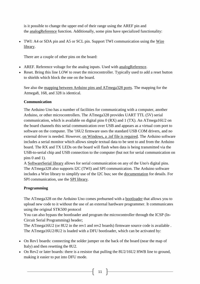
is it possible to change the upper end of their range using the AREF pin and
the analogReference function. Additionally, some pins have specialized functionality:
TWI: A4 or SDA pin and A5 or SCL pin. Support TWI communication using the Wire
library.
There are a couple of other pins on the board:
AREF. Reference voltage for the analog inputs. Used with analogReference.
Reset. Bring this line LOW to reset the microcontroller. Typically used to add a reset button
to shields which block the one on the board.
See also the mapping between Arduino pins and ATmega328 ports. The mapping for the
Atmega8, 168, and 328 is identical.
Communication
The Arduino Uno has a number of facilities for communicating with a computer, another
Arduino, or other microcontrollers. The ATmega328 provides UART TTL (5V) serial
communication, which is available on digital pins 0 (RX) and 1 (TX). An ATmega16U2 on
the board channels this serial communication over USB and appears as a virtual com port to
software on the computer. The '16U2 firmware uses the standard USB COM drivers, and no
external driver is needed. However, on Windows, a .inf file is required. The Arduino software
includes a serial monitor which allows simple textual data to be sent to and from the Arduino
board. The RX and TX LEDs on the board will flash when data is being transmitted via the
USB-to-serial chip and USB connection to the computer (but not for serial communication on
pins 0 and 1).
A SoftwareSerial library allows for serial communication on any of the Uno's digital pins.
The ATmega328 also supports I2C (TWI) and SPI communication. The Arduino software
includes a Wire library to simplify use of the I2C bus; see the documentation for details. For
SPI communication, use the SPI library.
Programming
The ATmega328 on the Arduino Uno comes preburned with a bootloader that allows you to
upload new code to it without the use of an external hardware programmer. It communicates
using the original STK500 protocol
You can also bypass the bootloader and program the microcontroller through the ICSP (In-
Circuit Serial Programming) header;
The ATmega16U2 (or 8U2 in the rev1 and rev2 boards) firmware source code is available .
The ATmega16U2/8U2 is loaded with a DFU bootloader, which can be activated by:
On Rev1 boards: connecting the solder jumper on the back of the board (near the map of
Italy) and then resetting the 8U2.
On Rev2 or later boards: there is a resistor that pulling the 8U2/16U2 HWB line to ground,
making it easier to put into DFU mode.
12
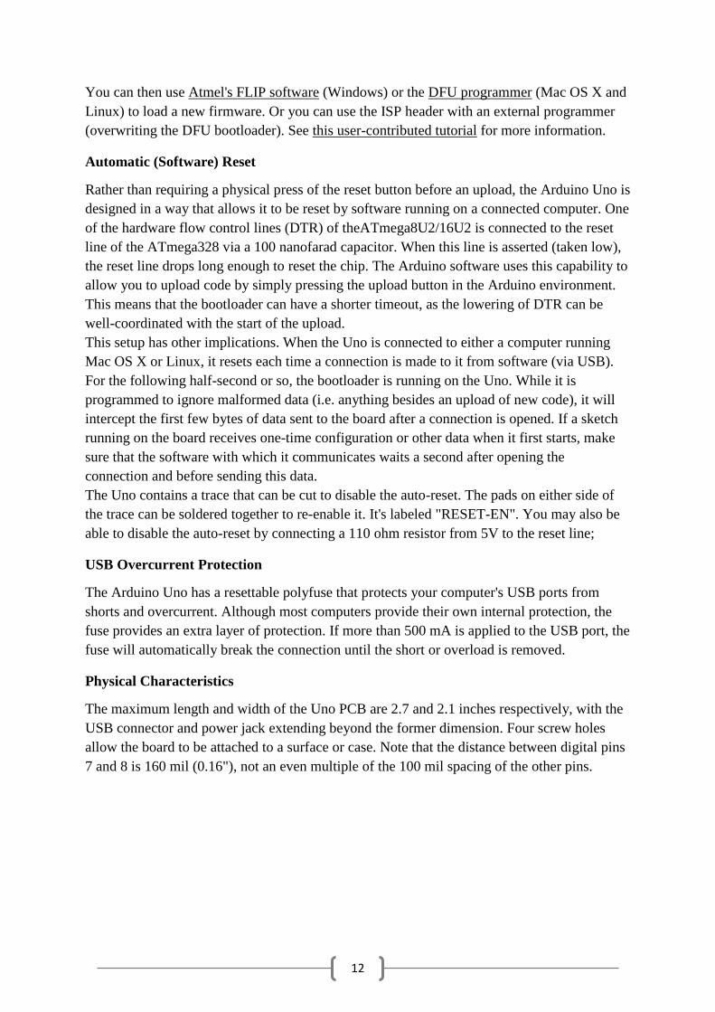
You can then use Atmel's FLIP software (Windows) or the DFU programmer (Mac OS X and
Linux) to load a new firmware. Or you can use the ISP header with an external programmer
(overwriting the DFU bootloader). See this user-contributed tutorial for more information.
Automatic (Software) Reset
Rather than requiring a physical press of the reset button before an upload, the Arduino Uno is
designed in a way that allows it to be reset by software running on a connected computer. One
of the hardware flow control lines (DTR) of theATmega8U2/16U2 is connected to the reset
line of the ATmega328 via a 100 nanofarad capacitor. When this line is asserted (taken low),
the reset line drops long enough to reset the chip. The Arduino software uses this capability to
allow you to upload code by simply pressing the upload button in the Arduino environment.
This means that the bootloader can have a shorter timeout, as the lowering of DTR can be
well-coordinated with the start of the upload.
This setup has other implications. When the Uno is connected to either a computer running
Mac OS X or Linux, it resets each time a connection is made to it from software (via USB).
For the following half-second or so, the bootloader is running on the Uno. While it is
programmed to ignore malformed data (i.e. anything besides an upload of new code), it will
intercept the first few bytes of data sent to the board after a connection is opened. If a sketch
running on the board receives one-time configuration or other data when it first starts, make
sure that the software with which it communicates waits a second after opening the
connection and before sending this data.
The Uno contains a trace that can be cut to disable the auto-reset. The pads on either side of
the trace can be soldered together to re-enable it. It's labeled "RESET-EN". You may also be
able to disable the auto-reset by connecting a 110 ohm resistor from 5V to the reset line;
USB Overcurrent Protection
The Arduino Uno has a resettable polyfuse that protects your computer's USB ports from
shorts and overcurrent. Although most computers provide their own internal protection, the
fuse provides an extra layer of protection. If more than 500 mA is applied to the USB port, the
fuse will automatically break the connection until the short or overload is removed.
Physical Characteristics
The maximum length and width of the Uno PCB are 2.7 and 2.1 inches respectively, with the
USB connector and power jack extending beyond the former dimension. Four screw holes
allow the board to be attached to a surface or case. Note that the distance between digital pins
7 and 8 is 160 mil (0.16"), not an even multiple of the 100 mil spacing of the other pins.
13
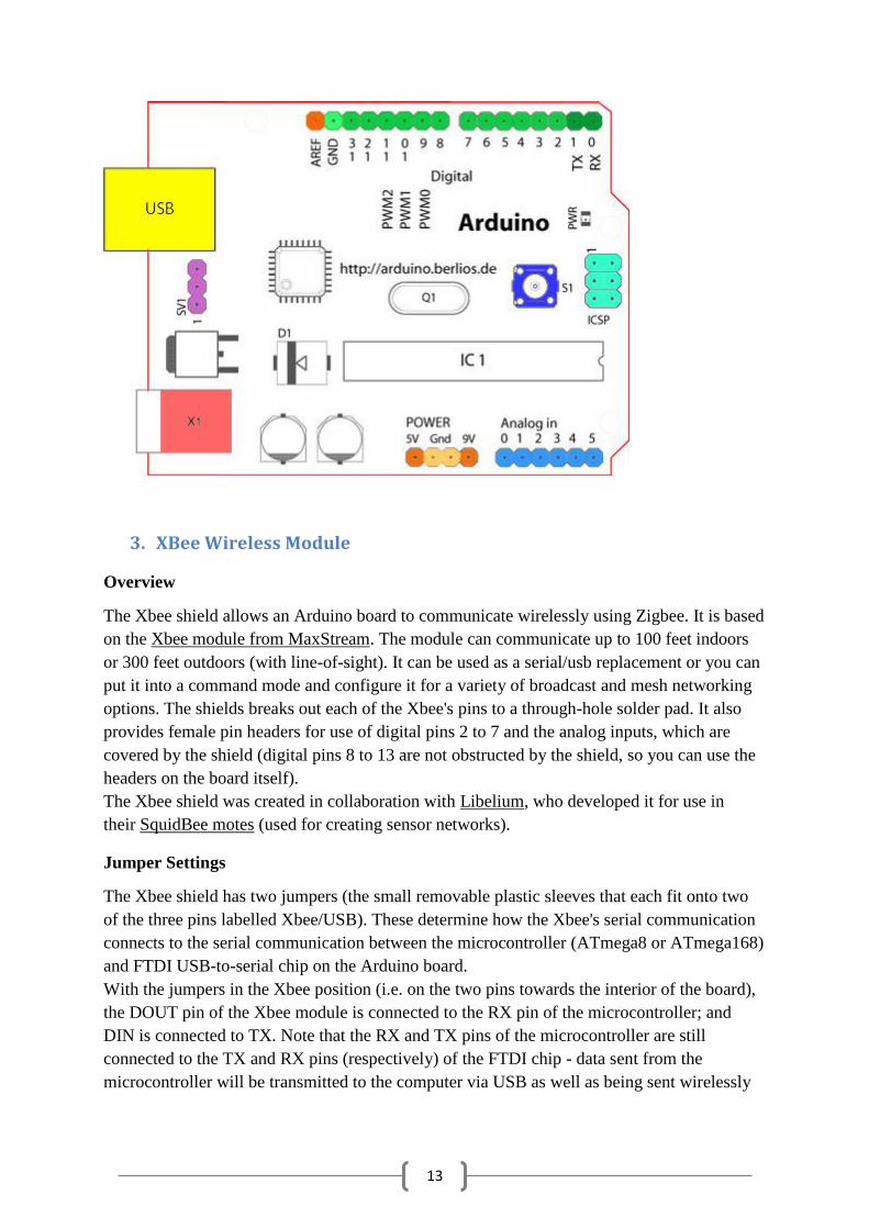
3. XBee Wireless Module
Overview
The Xbee shield allows an Arduino board to communicate wirelessly using Zigbee. It is based
on the Xbee module from MaxStream. The module can communicate up to 100 feet indoors
or 300 feet outdoors (with line-of-sight). It can be used as a serial/usb replacement or you can
put it into a command mode and configure it for a variety of broadcast and mesh networking
options. The shields breaks out each of the Xbee's pins to a through-hole solder pad. It also
provides female pin headers for use of digital pins 2 to 7 and the analog inputs, which are
covered by the shield (digital pins 8 to 13 are not obstructed by the shield, so you can use the
headers on the board itself).
The Xbee shield was created in collaboration with Libelium, who developed it for use in
their SquidBee motes (used for creating sensor networks).
Jumper Settings
The Xbee shield has two jumpers (the small removable plastic sleeves that each fit onto two
of the three pins labelled Xbee/USB). These determine how the Xbee's serial communication
connects to the serial communication between the microcontroller (ATmega8 or ATmega168)
and FTDI USB-to-serial chip on the Arduino board.
With the jumpers in the Xbee position (i.e. on the two pins towards the interior of the board),
the DOUT pin of the Xbee module is connected to the RX pin of the microcontroller; and
DIN is connected to TX. Note that the RX and TX pins of the microcontroller are still
connected to the TX and RX pins (respectively) of the FTDI chip - data sent from the
microcontroller will be transmitted to the computer via USB as well as being sent wirelessly
14
by the Xbee module. The microcontroller, however, will only be able to receive data from the
Xbee module, not over USB from the computer.
With the jumpers in the USB position (i.e. on the two pins nearest the edge of the board), the
DOUT pin the Xbee module is connected to the RX pin of the FTDI chip, and DIN on the
Xbee module is connected to the TX pin of the FTDI chip. This means that the Xbee module
can communicate directly with the computer - however, this only works if the microcontroller
has been removed from the Arduino board. If the microcontroller is left in the Arduino board,
it will be able to talk to the computer normally via USB, but neither the computer nor the
microcontroller will be able to talk to the Xbee module.
Networking
The Arduino XBee shield can be used with different XBee modules. The instructions below
are for the XBee 802.15.4 modules (sometimes called "Series 1" to distinguish them from the
Series 2 modules, although "Series 1" doesn't appear in the official name or product
description).
Addressing
There are multiple parameters that need to be configured correctly for two modules to talk to
each other (although with the default settings, all modules should be able to talk to each
other). They need to be on the same network, as set by the ID parameter (see "Configuration"
below for more details on the parameters). The modules need to be on the same channel, as
set by the CH parameter. Finally, a module's destination address (DH and DL parameters)
determine which modules on its network and channel will receive the data it transmits. This
can happen in a few ways:
If a module's DH is 0 and its DL is less than 0xFFFF (i.e. 16 bits), data transmitted by that
module will be received by any module whose 16-bit address MY parameter equals DL.
If DH is 0 and DL equals 0xFFFF, the module's transmissions will be received by all
modules.
If DH is non-zero or DL is greater than 0xFFFF, the transmission will only be received by the
module whose serial number equals the transmitting module's destination address (i.e.
whose SH equals the transmitting module's DH and whose SL equals its DL).
Again, this address matching will only happen between modules on the same network and
channel. If two modules are on different networks or channels, they can't communicate
regardless of their addresses.
Configuration
Here are some of the more useful parameters for configuring your Xbee module. For step-by-
step instructions on reading and writing them, see the guide to the Xbee shield. Make sure to
prepend AT to the parameter name when sending a command to the module (e.g. to read
the ID parameter, you should send the command ATID).
15
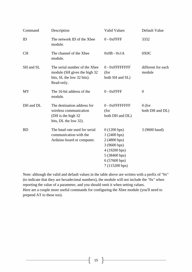
Command Description Valid Values Default Value
ID The network ID of the Xbee
module.
0 - 0xFFFF 3332
CH The channel of the Xbee
module.
0x0B - 0x1A 0X0C
SH and SL The serial number of the Xbee
module (SH gives the high 32
bits, SL the low 32 bits).
Read-only.
0 - 0xFFFFFFFF
(for
both SH and SL)
different for each
module
MY The 16-bit address of the
module.
0 - 0xFFFF 0
DH and DL The destination address for
wireless communication
(DH is the high 32
bits, DL the low 32).
0 - 0xFFFFFFFF
(for
both DH and DL)
0 (for
both DH and DL)
BD The baud rate used for serial
communication with the
Arduino board or computer.
0 (1200 bps)
1 (2400 bps)
2 (4800 bps)
3 (9600 bps)
4 (19200 bps)
5 (38400 bps)
6 (57600 bps)
7 (115200 bps)
3 (9600 baud)
Note: although the valid and default values in the table above are written with a prefix of "0x"
(to indicate that they are hexadecimal numbers), the module will not include the "0x" when
reporting the value of a parameter, and you should omit it when setting values.
Here are a couple more useful commands for configuring the Xbee module (you'll need to
prepend AT to these too).
16
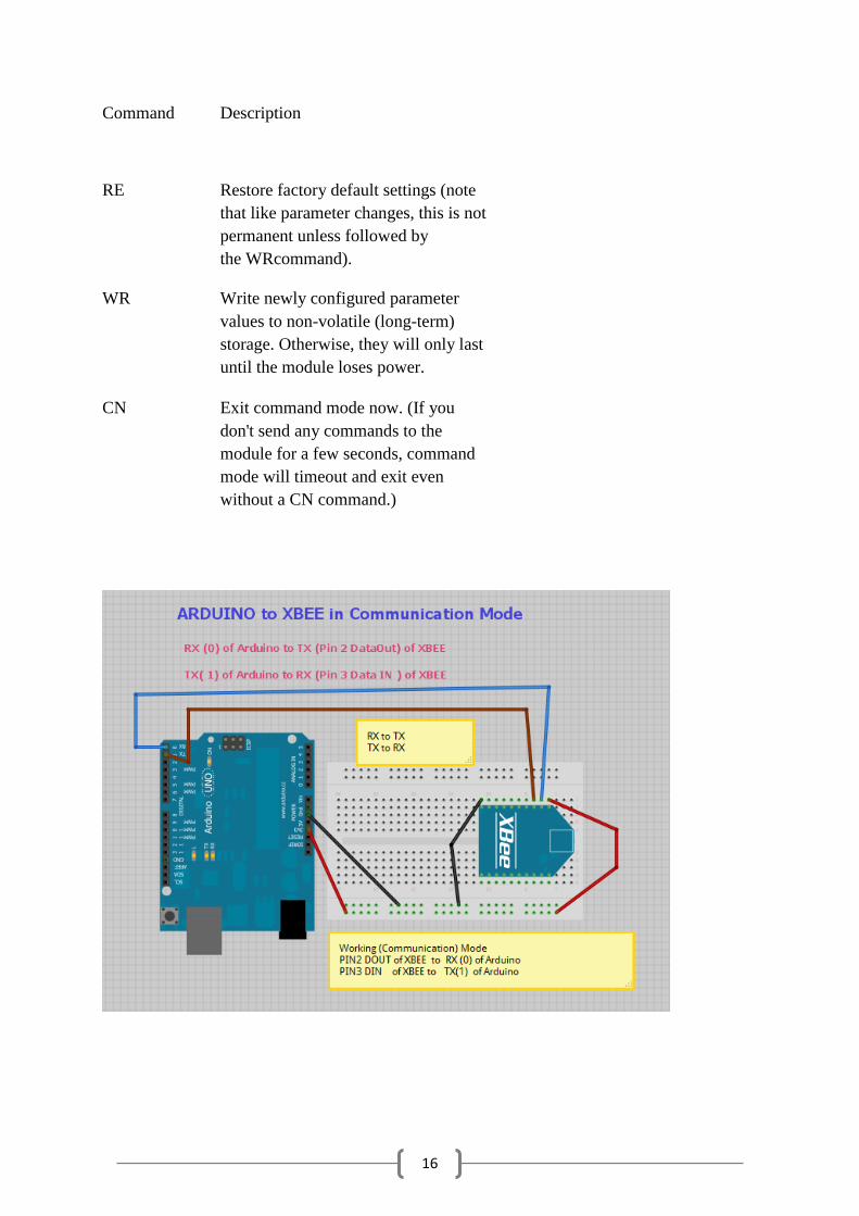
Command Description
RE Restore factory default settings (note
that like parameter changes, this is not
permanent unless followed by
the WRcommand).
WR Write newly configured parameter
values to non-volatile (long-term)
storage. Otherwise, they will only last
until the module loses power.
CN Exit command mode now. (If you
don't send any commands to the
module for a few seconds, command
mode will timeout and exit even
without a CN command.)
17
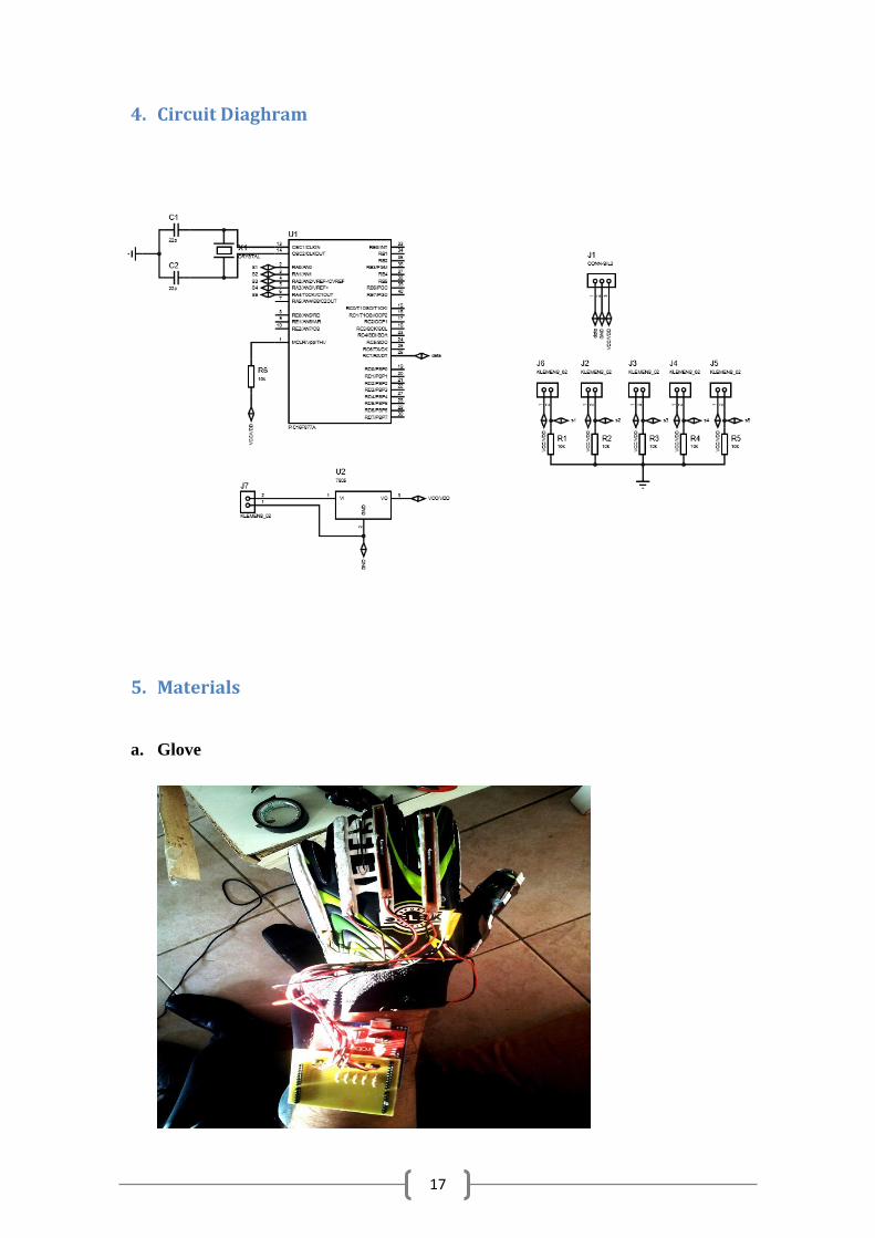
4. Circuit Diaghram
5. Materials
a. Glove

18
b. Adaptor
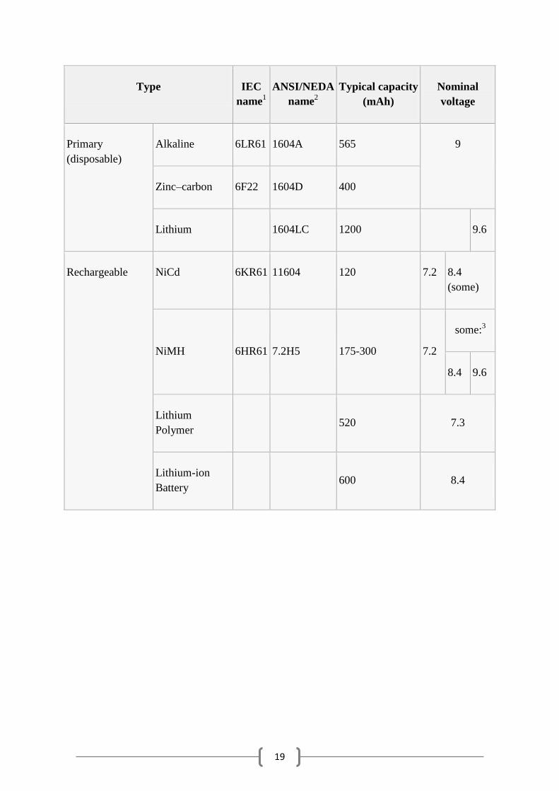
These batteries are commonly named 9-volt, and also colloquially named PP3, Radio battery,
Square battery, and Japan "006P".
They all have a rectangular shape; the dimensions are height 48.5 mm, length 26.5 mm, width
17.5 mm (or 1.9"x1.0"x0.68"). Both terminals are at one end and their centers are 1/2 inch
(12.7 mm) apart.
Inside an alkaline or carbon-zinc 9-volt battery there are six cells, either cylindrical or flat
type, connected in series. Some brands use welded tabs internally to attach to the cells, others
press foil strips against the ends of the cells.
Rechargeable nickel–cadmium (NiCd) and Nickel-metal hydride (NiMH) batteries have
between six and eight 1.2 volt cells. Lithium ion versions typically use two cells (3.7V
nominal each). Lithium polymer and low self-discharge NiMH versions can also be found.
Formerly, mercury batteries were made in this size. They had higher capacity than carbon-
zinc types, a nominal voltage of 8.4 volts, and very stable voltage output. Once used in
photographic and measuring instruments or long-life applications, they are now unavailable
due to environmental restrictions.
19
Type IEC
name1
ANSI/NEDA
name2
Typical capacity
(mAh)
Nominal
voltage
Primary
(disposable)
Alkaline 6LR61 1604A 565 9
Zinc–carbon 6F22 1604D 400
Lithium
1604LC 1200
9.6
Rechargeable NiCd 6KR61 11604 120 7.2 8.4
(some)
NiMH 6HR61 7.2H5 175-300 7.2
some:3
8.4 9.6
Lithium
Polymer
520 7.3
Lithium-ion
Battery
600 8.4
20
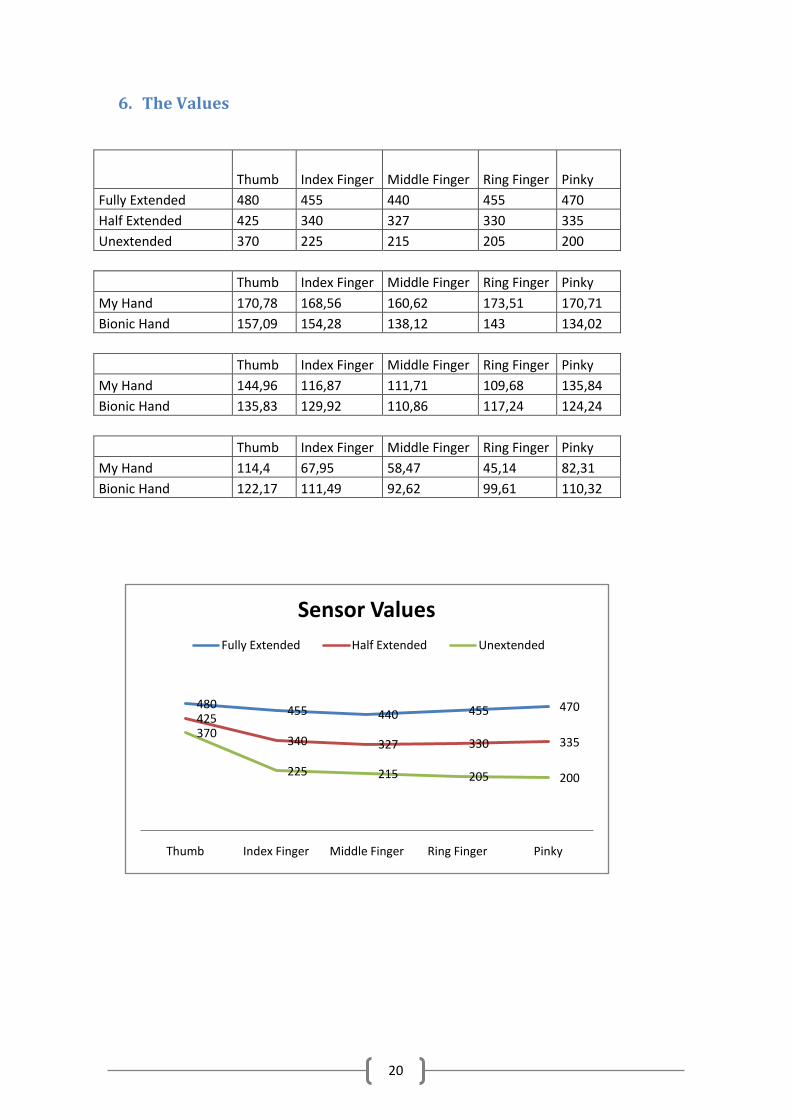
6. The Values
Thumb Index Finger Middle Finger Ring Finger Pinky
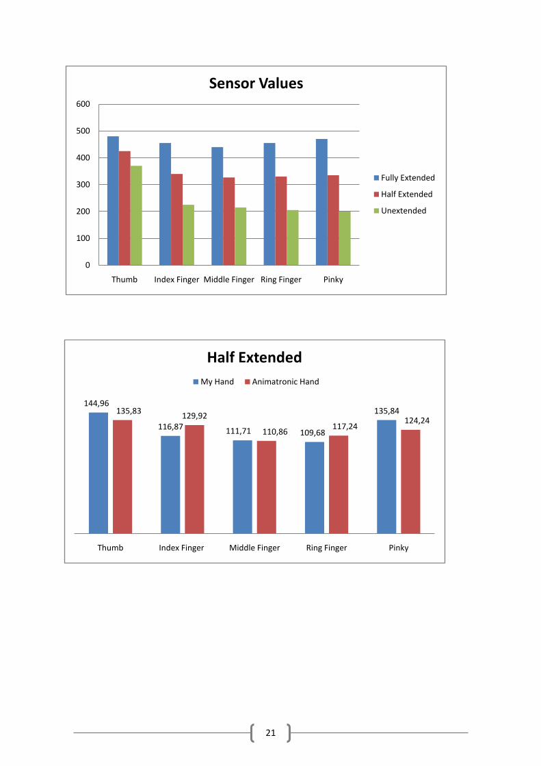
Fully Extended 480 455 440 455 470 Half Extended 425 340 327 330 335 Unextended 370 225 215 205 200
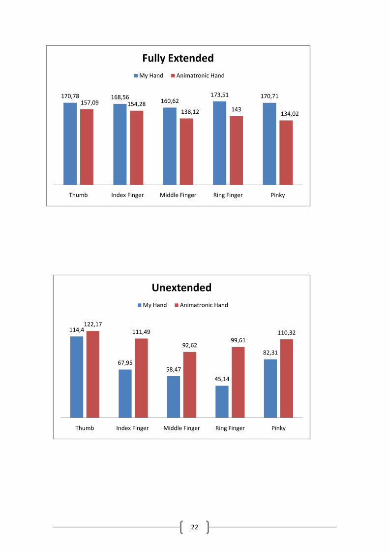
Thumb Index Finger Middle Finger Ring Finger Pinky My Hand 170,78 168,56 160,62 173,51 170,71 Bionic Hand 157,09 154,28 138,12 143 134,02
Thumb Index Finger Middle Finger Ring Finger Pinky My Hand 144,96 116,87 111,71 109,68 135,84 Bionic Hand 135,83 129,92 110,86 117,24 124,24
Thumb Index Finger Middle Finger Ring Finger Pinky My Hand 114,4 67,95 58,47 45,14 82,31 Bionic Hand 122,17 111,49 92,62 99,61 110,32
480 455 440 455 470425
340 327 330 335370
225 215 205 200
Thumb Index Finger Middle Finger Ring Finger Pinky
Sensor Values
Fully Extended Half Extended Unextended
170,78 168,56 160,62173,51 170,71
157,09 154,28138,12 143
134,02
Thumb Index Finger Middle Finger Ring Finger Pinky
Fully Extended
My Hand Animatronic Hand
144,96
116,87 111,71 109,68
135,84135,83 129,92
110,86 117,24124,24
Thumb Index Finger Middle Finger Ring Finger Pinky
Half Extended
My Hand Animatronic Hand
21
144,96
116,87 111,71 109,68
135,84135,83129,92
110,86117,24
124,24
Thumb Index Finger Middle Finger Ring Finger Pinky
Half Extended
My Hand Animatronic Hand
0
100
200
300
400
500
600
Thumb Index Finger Middle Finger Ring Finger Pinky
Sensor Values
Fully Extended
Half Extended
Unextended
22
170,78 168,56160,62
173,51 170,71157,09 154,28
138,12 143134,02
Thumb Index Finger Middle Finger Ring Finger Pinky
Fully Extended
My Hand Animatronic Hand
114,4
67,9558,47
45,14
82,31
122,17111,49
92,6299,61
110,32
Thumb Index Finger Middle Finger Ring Finger Pinky
Unextended
My Hand Animatronic Hand
23
B. ARDUINO WIRELESS BIONIC HAND
1. Arduino User Guide
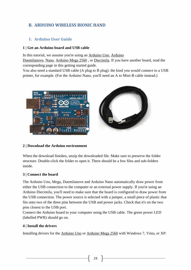
1 | Get an Arduino board and USB cable
In this tutorial, we assume you're using an Arduino Uno, Arduino
Duemilanove, Nano, Arduino Mega 2560 , or Diecimila. If you have another board, read the
corresponding page in this getting started guide.
You also need a standard USB cable (A plug to B plug): the kind you would connect to a USB
printer, for example. (For the Arduino Nano, you'll need an A to Mini-B cable instead.)
2 | Download the Arduino environment
When the download finishes, unzip the downloaded file. Make sure to preserve the folder
structure. Double-click the folder to open it. There should be a few files and sub-folders
inside.
3 | Connect the board
The Arduino Uno, Mega, Duemilanove and Arduino Nano automatically draw power from
either the USB connection to the computer or an external power supply. If you're using an
Arduino Diecimila, you'll need to make sure that the board is configured to draw power from
the USB connection. The power source is selected with a jumper, a small piece of plastic that
fits onto two of the three pins between the USB and power jacks. Check that it's on the two
pins closest to the USB port.
Connect the Arduino board to your computer using the USB cable. The green power LED
(labelled PWR) should go on.
4 | Install the drivers
Installing drivers for the Arduino Uno or Arduino Mega 2560 with Windows 7, Vista, or XP:

24
Plug in your board and wait for Windows to begin it's driver installation process. After a few
moments, the process will fail, despite its best efforts
Click on the Start Menu, and open up the Control Panel.
While in the Control Panel, navigate to System and Security. Next, click on System. Once the
System window is up, open the Device Manager.
Look under Ports (COM & LPT). You should see an open port named "Arduino UNO
(COMxx)". If there is no COM & LPT section, look under "Other Devices" for "Unknown
Device".
Right click on the "Arduino UNO (COmxx)" port and choose the "Update Driver Software"
option.
Next, choose the "Browse my computer for Driver software" option.
Finally, navigate to and select the driver file named "arduino.inf", located in the "Drivers"
folder of the Arduino Software download (not the "FTDI USB Drivers" sub-directory). If you
are using an old version of the IDE (1.0.3 or older), choose the Uno driver file
named "Arduino UNO.inf"
Windows will finish up the driver installation from there.
Installing drivers for the Arduino Duemilanove, Nano, or Diecimila with Windows7, Vista, or
XP:
When you connect the board, Windows should initiate the driver installation process (if you
haven't used the computer with an Arduino board before).
On Windows Vista, the driver should be automatically downloaded and installed. (Really, it
works!)
On Windows XP, the Add New Hardware wizard will open:
When asked Can Windows connect to Windows Update to search for software? select No, not
this time. Click next.
Select Install from a list or specified location (Advanced) and click next.
Make sure that Search for the best driver in these locations is checked; uncheck Search
removable media; check Include this location in the search and browse to the drivers/FTDI
USB Drivers directory of the Arduino distribution. Click next.
The wizard will search for the driver and then tell you that a "USB Serial Converter" was
found. Click finish.
The new hardware wizard will appear again. Go through the same steps and select the same
options and location to search. This time, a "USB Serial Port" will be found.
You can check that the drivers have been installed by opening the Windows Device Mananger
(in the Hardware tab of System control panel). Look for a "USB Serial Port" in the Ports
section; that's the Arduino board.
5 | Launch the Arduino application
Double-click the Arduino application. (Note: if the Arduino software loads in the wrong
language, you can change it in the preferences dialog. See the environment page for details.)
25
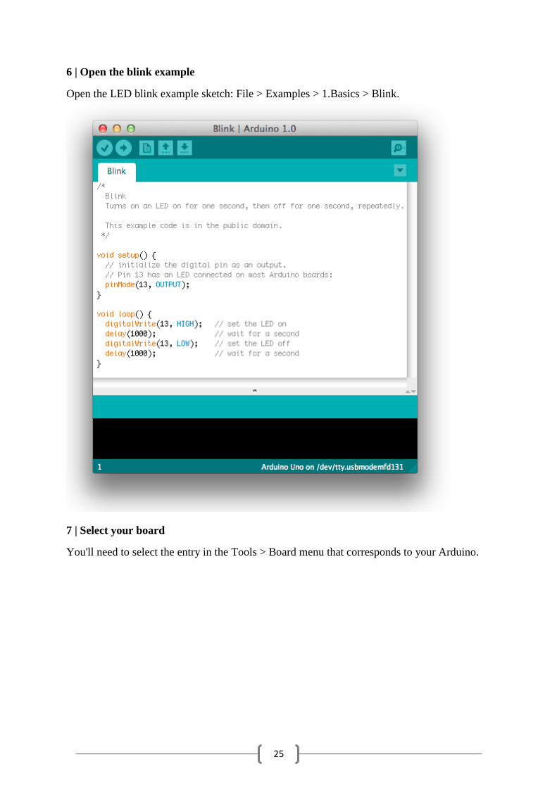
6 | Open the blink example
Open the LED blink example sketch: File > Examples > 1.Basics > Blink.
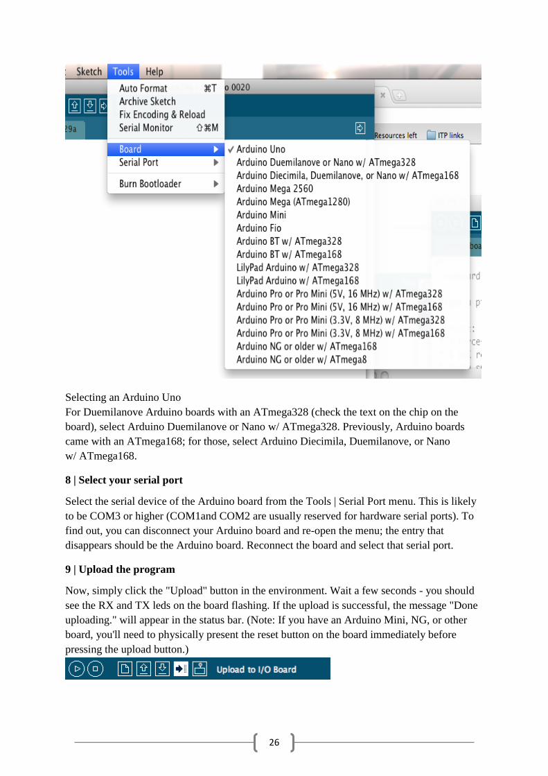
7 | Select your board
You'll need to select the entry in the Tools > Board menu that corresponds to your Arduino.
26
Selecting an Arduino Uno
For Duemilanove Arduino boards with an ATmega328 (check the text on the chip on the
board), select Arduino Duemilanove or Nano w/ ATmega328. Previously, Arduino boards
came with an ATmega168; for those, select Arduino Diecimila, Duemilanove, or Nano
w/ ATmega168.
8 | Select your serial port
Select the serial device of the Arduino board from the Tools | Serial Port menu. This is likely
to be COM3 or higher (COM1and COM2 are usually reserved for hardware serial ports). To
find out, you can disconnect your Arduino board and re-open the menu; the entry that
disappears should be the Arduino board. Reconnect the board and select that serial port.
9 | Upload the program
Now, simply click the "Upload" button in the environment. Wait a few seconds - you should
see the RX and TX leds on the board flashing. If the upload is successful, the message "Done
uploading." will appear in the status bar. (Note: If you have an Arduino Mini, NG, or other
board, you'll need to physically present the reset button on the board immediately before
pressing the upload button.)
27
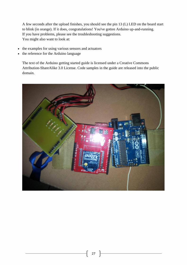
A few seconds after the upload finishes, you should see the pin 13 (L) LED on the board start
to blink (in orange). If it does, congratulations! You've gotten Arduino up-and-running.
If you have problems, please see the troubleshooting suggestions.
You might also want to look at:
the examples for using various sensors and actuators
the reference for the Arduino language
The text of the Arduino getting started guide is licensed under a Creative Commons
Attribution-ShareAlike 3.0 License. Code samples in the guide are released into the public
domain.
28
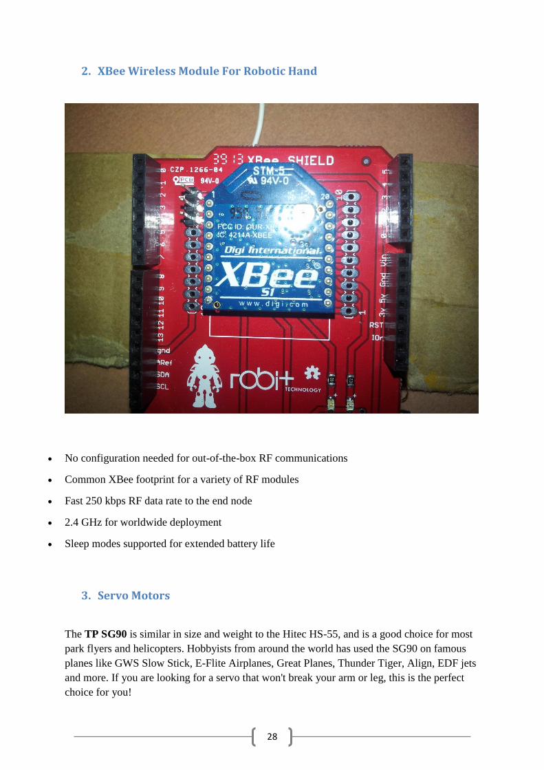
2. XBee Wireless Module For Robotic Hand
No configuration needed for out-of-the-box RF communications
Common XBee footprint for a variety of RF modules
Fast 250 kbps RF data rate to the end node
2.4 GHz for worldwide deployment
Sleep modes supported for extended battery life
3. Servo Motors
The TP SG90 is similar in size and weight to the Hitec HS-55, and is a good choice for most
park flyers and helicopters. Hobbyists from around the world has used the SG90 on famous
planes like GWS Slow Stick, E-Flite Airplanes, Great Planes, Thunder Tiger, Align, EDF jets
and more. If you are looking for a servo that won't break your arm or leg, this is the perfect
choice for you!
29
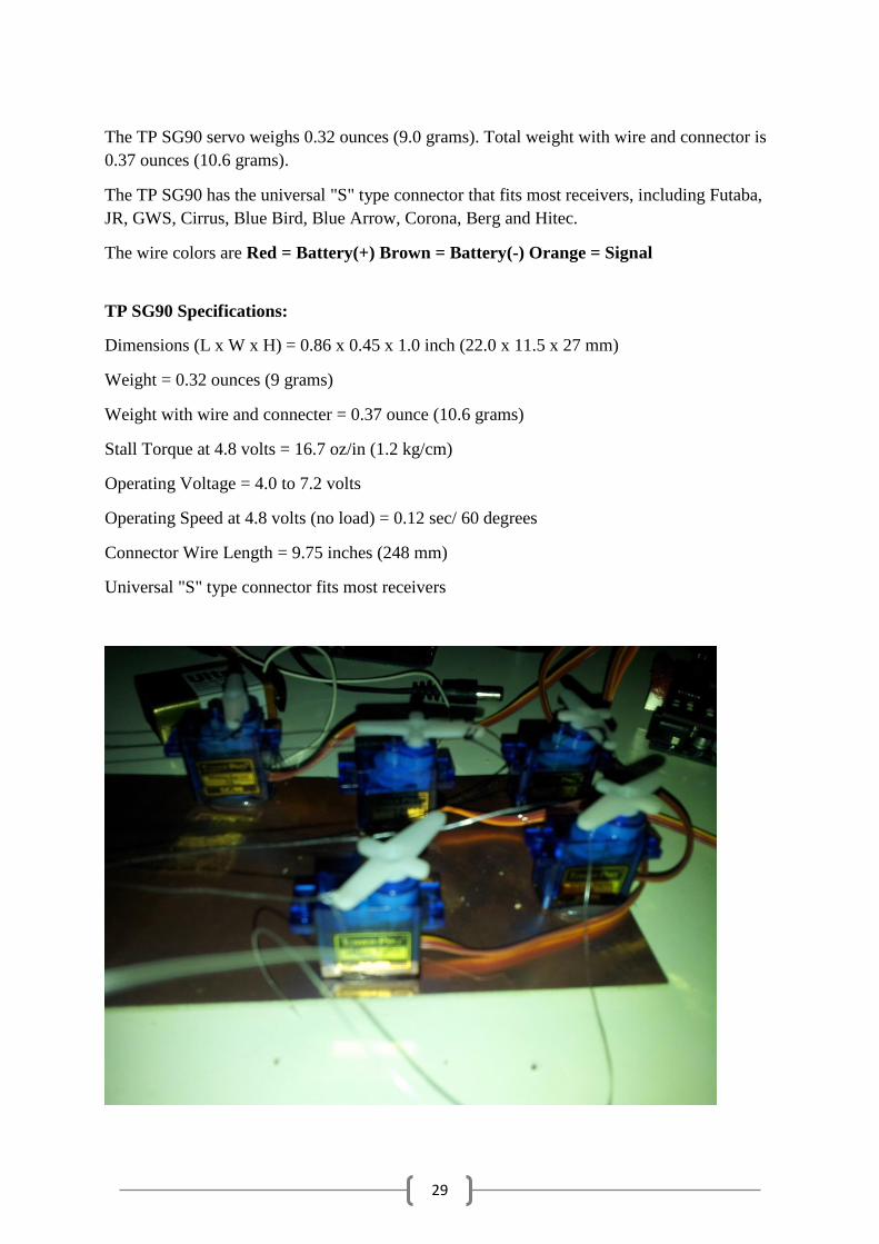
The TP SG90 servo weighs 0.32 ounces (9.0 grams). Total weight with wire and connector is
0.37 ounces (10.6 grams).
The TP SG90 has the universal "S" type connector that fits most receivers, including Futaba,
JR, GWS, Cirrus, Blue Bird, Blue Arrow, Corona, Berg and Hitec.
The wire colors are Red = Battery(+) Brown = Battery(-) Orange = Signal
TP SG90 Specifications:
Dimensions (L x W x H) = 0.86 x 0.45 x 1.0 inch (22.0 x 11.5 x 27 mm)
Weight = 0.32 ounces (9 grams)
Weight with wire and connecter = 0.37 ounce (10.6 grams)
Stall Torque at 4.8 volts = 16.7 oz/in (1.2 kg/cm)
Operating Voltage = 4.0 to 7.2 volts
Operating Speed at 4.8 volts (no load) = 0.12 sec/ 60 degrees
Connector Wire Length = 9.75 inches (248 mm)
Universal "S" type connector fits most receivers

30
31
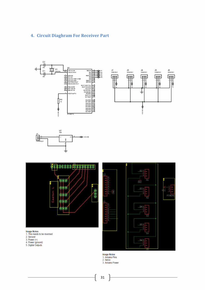
4. Circuit Diaghram For Receiver Part

32
5. Code
The very first thing we want to do is our shield or Xbee s are unplugged from the Arduino.Or
make sure the correct jumpers are in the right place .We have written this code:
int Finger1 = 0;
int Finger2 = 1;
int Finger3 = 2; int Finger4 = 3;
int Finger5 = 4;
void setup()
{
Serial.begin(9600);
}
void loop()
{ byte servoValue1;
byte servoValue2;
byte servoValue3;
byte servoValue4;
byte servoValue5;
int FingerV1 = analogRead(Finger1);
int FingerV2 = analogRead(Finger2);
int FingerV3 = analogRead(Finger3);
int FingerV4 = analogRead(Finger4);
int FingerV5 = analogRead(Finger5);
if (FingerV1 < 200) FingerV1 = 200;
else if (FingerV1 > 460) FingerV1 = 460;
if (FingerV2 < 200) FingerV2 = 200;
else if (FingerV2 > 460) FingerV2 = 460;
33
if (FingerV3 < 200) FingerV3 = 200;
else if (FingerV3 > 460) FingerV3 = 460;
if (FingerV4 < 200) FingerV4 = 200;
else if (FingerV4 > 460) FingerV4 = 460;
if (FingerV5 < 200) FingerV5 = 200;
else if (FingerV5 > 460) FingerV5 = 460;
byte servoVal1 = map(FingerV1,460, 200, 255, 0);
byte servoVal2 = map(FingerV2,460, 200, 255, 0);
byte servoVal3 = map(FingerV3,460, 200, 255, 0);
byte servoVal4 = map(FingerV4,460, 200, 255, 0);
byte servoVal5 = map(FingerV5,460, 200, 255, 0);
Serial.print(servoVal1);
Serial.print(servoVal2);
Serial.print(servoVal3);
Serial.print(servoVal4);
Serial.print(servoVal5);
delay(100);
}
Here is the receiving:
#include
Servo myservo1; // create servo object to control a servo
Servo myservo2;
Servo myservo3;
Servo myservo4;
Servo myservo5;
void setup()
{

34
Serial.begin(9600);
myservo1.attach(2); // attaches the servo on pin 9 to the servo object
myservo2.attach(3);
myservo3.attach(4);
myservo4.attach(5);
myservo5.attach(6);
}
void loop()
{
if(Serial.available() >=5)
{
byte servoAng1 = Serial.read();
byte servoAng2 = Serial.read();
byte servoAng3 = Serial.read();
byte servoAng4 = Serial.read();
byte servoAng5 = Serial.read();
// Send the servo to the position read... (note: you get to make this happen)
myservo1.write(servoAng1);
myservo2.write(servoAng2);
myservo3.write(servoAng3);
myservo4.write(servoAng4);
myservo5.write(servoAng5);
}
}
35
6. Materials For Bionic Part
a. Adaptor
i. 5V for Servo Motors
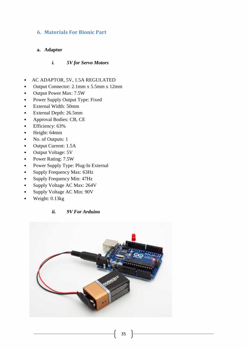
AC ADAPTOR, 5V, 1.5A REGULATED
Output Connector: 2.1mm x 5.5mm x 12mm
Output Power Max: 7.5W
Power Supply Output Type: Fixed
External Width: 50mm
External Depth: 26.5mm
Approval Bodies: CB, CE
Efficiency: 63%
Height: 64mm
No. of Outputs: 1
Output Current: 1.5A
Output Voltage: 5V
Power Rating: 7.5W
Power Supply Type: Plug-In External
Supply Frequency Max: 63Hz
Supply Frequency Min: 47Hz
Supply Voltage AC Max: 264V
Supply Voltage AC Min: 90V
Weight: 0.13kg
ii. 9V For Arduino
36
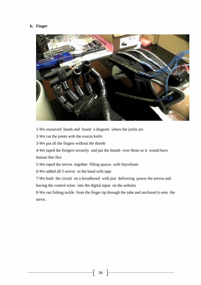
b. Finger
1-We researced hands and found a diagram where the jonits are
2-We cut the joints with the exacto knife
3-We put all the fingers without the thumb
4-We taped the firngers securely and put the thumb over those so it would have
human like flex
5-We taped the servos together filling spaces with Styrofoam
6-We added all 5 servos to the hand with tape
7-We built the circuit on a breadboard with just delivering power the servos and
having the control wires into the digital input on the arduino
8-We ran fishing tackle from the finger tip through the tube and anchored it onto the
servo.
37
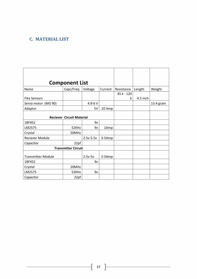
C. MATERIAL LIST
Component List
Name Capc/Freq Voltage Current Resistance Length Weight
Flex Sensors 45 k - 120
k 4.5 inch
Servo motor (MG 90) 4.8-6 V 13.4 gram
Adaptor 5V 10 Amp
Reciever Circuit Material
18F452 9v
LM2575 52KHz 9v 1Amp
Crystal 20MHz
Reciever Module 2.5v-5.5v 3-5Amp
Capacitor 22pf
Transmitter Circuit
Transmitter Module 2.5v-5v 3-5Amp
18F452 9v
Crystal 20MHz
LM2575 52KHz 9v
Capacitor 22pf