Embed Size (px)
Citation preview

Simulation and Verification of bionic heat exchangers with COMSOL
Multiphysics A. Kremers, M. Pieper

Bionic heat exchanger
• Analogy to blood vessel system
• Low pressure losses
• Low energy consumption
• Optimized for fluid transport
http://m.tk.de/centaurus/servlet/Bild/34341 [1], [2]
The idea

Experiments
• Production of 2 real heat exchangers
• Different cover plates for different experiments:
1. Pressure loss: glass cover plate, tab water at
room temp., pressure difference between in- and outlet
2. Temperature difference and behaviour: aluminium cover plate, heated tab water, temperature difference between in- and outlet, thermographic camera 3. General flow behaviour: glass cover plate,
special fluid to visualize flow behaviour, high definition camera

Simulations
• Same CAD model used for production of real heat exchangers and for simulations with COMSOL
• Flow velocities in laminar border zone Assumption: laminar flow
• Two simulation series:
1. Laminar flow, stationary (pressure loss &
flow behaviour)
2. Non-isothermal flow, time dependent (temperature difference & temperature behaviour)
• Data from experiments as input data for
simulations
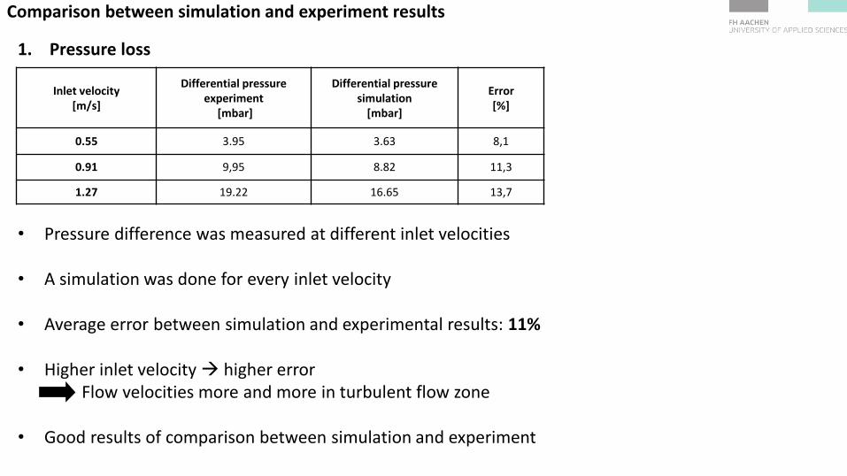
Comparison between simulation and experiment results
1. Pressure loss
• Pressure difference was measured at different inlet velocities
• A simulation was done for every inlet velocity
• Average error between simulation and experimental results: 11%
• Higher inlet velocity higher error Flow velocities more and more in turbulent flow zone • Good results of comparison between simulation and experiment
Inlet velocity [m/s]
Differential pressure experiment
[mbar]
Differential pressure simulation
[mbar]
Error [%]
0.55 3.95 3.63 8,1
0.91 9,95 8.82 11,3
1.27 19.22 16.65 13,7

Comparison between simulation and experiment results
2. General flow behaviour
• Very good results
• Good correspondence with respect to flow behavior
• COMSOL calculates swirls of same size and position

Comparison between simulation and experiment results
3. Temperature difference and behaviour
0
2
4
6
8
10
12
1 101 201
tem
per
atu
re [
°C]
time [s]
Comparison temperature difference experiment/simulation
simulation experiment
• Graphs do have similar trend, but are not congruent to each other
• Reasons:
Laminar flow model was used, but actually turbulent flow behaviour in some spots
Material data of aluminum of real heat exchangers was not exactly known
Material data of COMSOL material library was used

3. Temperature difference and behaviour
• Left: COMSOL
• Right: Thermographic camera
• Nearly equal pictures at the same time • Very good correspondence
Comparison between simulation and experiment results

Comparison between simulation and experiment results
Conclusion: • The comparison between simulations and experiments shows positive results
• The error between simulation and experiment results is dependent on the particular physical
parameter
• Pressure loss: Average error: 11%
• General flow behaviour: COMSOL results are equal to experiment results
• Temperature difference and behaviour: Temperature differences show a similar trend, but are not congruent. The pictures of the thermographic camera are nearly equal to the simulation results
Comsol Multiphysics® can be verified as an extremely useful tool to design and test physical and technical processes

Sources:
[1]: M. Pieper, P. Klein: A simple and accurate numerical network flow model for bionic micro heat exchanger [2]: M. Herrmann: „Bionische ansätze zur Entwicklung energieeffizienter Fluidsysteme für den Wärmetransport“, PhD-Thesis, University of Karlsruhe, 2005

Improvement of the bionic heat exchanger design

• Development of 3D-CAD model according to an optimized 2D model
• Channels become smaller after every branching
• Mirroring of structure for perfect symmetry
• Optimizing CAD model for simulation reasons
• Simulation with optimized CAD model runs fast and without any problems
Simplifying the CAD model can speed up your simulation
3D CAD structure

Vielen Dank für ihre Aufmerksamkeit!