Embed Size (px)
Citation preview
8/7/2019 border haig
http://slidepdf.com/reader/full/border-haig 1/6
Border following : new definition gives improvedborders
T.D. Haig, BEY. Attikiouzel, BSc, PhDM.D. Alder, MEngSc, PhD
Indexing terms: A lgorith m, Image processing, Picture processing and pattern recognition
Abstract: Border following is widely used in thepreprocessing of many binary images. Images maybe taken to consist of a set of black objects on awhite background, or vice versa, and the objectsmay have holes in them; some of the holes maycontain objects, and this may be repeated. Findingthe borders of the objects allows considerablecompression and has other advantages, but ismore difficult than may appear at first sight. Inparticular, it is not dificult to obtain algorithmswhich produce reentrant curves as candidate
borders, and othe rs which produce borders whichare unsatisfactory for various reasons. The paperdescribes a co-recursive algorithm obtained from anew definition of borders. Because of somecounter-intuitive aspects of the subject, it wasnecessary to prove that the algorithm produces aborder in the sense of the paper. Experiments on avariety of images are described, and the resultsshow that the borders described in the paper aregenerally smaller and better connected than someothers.
1 Introduction
Border-following techniques have a wide variety of appli-cations, including picture recognition, topologicalanalysis, object counting and image compression. Thepresent work aro se from the reconstruction of biomedicalobjects from images of sections; such images pose asevere test for border-following algorithms, partlybecause of the complex shape of the boundaries, andpartly bec ause noise often remains after the commonnoise-reduction techniques have been applied.
We may define a border-following algorithm by suppos-ing that a binary two-dimensional raster image is pre-sented to the algorithm, and some indeterminate numberof chain code sequences, of indeterminate length, isoutput, together with some pixel on each chain codesequence. Not all algorithms are in precisely this form,but enough are equivalent to it, or are variants of it, tojustify this a s a n introductory definition. Such algorithmshave been studied by Rosenfeld and Kak [l ] and Pavlidis[2 ] , who offer a variety of solutions. More recently,Suzuki and Abe [3] and Ly and Attikiouzel [4] have
Paper 84691 (E4 ), received 16th July 1991Mr. Haig an d Prof. Attikiouzel are with the Departm ent of Electricaland Electronic Engineering, and Dr. Alder is with the Department ofMathematics, The University of Western Australia, Nedlands, Perth,WA 6009, Australia
206
described others. Kruse [SI and Danielsson [6] haveinvestigated multilevel images, and methods for tracingthree-dimensional voxel image sets have been presentedby Toriwaki and Yokoi [7]. Chen and Siy [SI have pro-posed a technique which uses a priori knowledge andfeedback to improve gradually the border extraction.
These existing methods can find and trace outermostborders even when there may be several objects in theimage; when the image contains objects having holes inthem, and objects inside the holes, recursively severallevels deep, the inner borders tend to be unsatisfactory, asmay be discovered experimentally. In general, it is the
‘hole borders’ which are incorrectly traced. This paperproposes a new method which avoids these deficiencies.As is plain from the general literature on image pro-
cessing (e.g. Pavlidis [Z]), there are some subtleties ingoing to a discrete binary array of pixels, with naiveexpectations based on the topology of the euclideanplane. If, for example, we assume that two pixels of thesame colour are adjacent if they share a common edgeor corner, then a simple closed curve may be defined asa sequence of such adjacent pixels, all of the same colour,the first pixel and the last also being adjacent, and allother pixels adjacent to any pixels of the sequence beingof the oppos ite colour. Unlike the corresponding case inthe plane, however, such a simple closed curve fails toseparate the plane into two disconnected components.This is one form of the connectivity paradox. So thereasoning about algorithms which operate on pixelarrays has t o be done with extreme care if it is not to fall
victim to some piece of ‘common sense’ which is in factwrong: it is intuitively plausible that the boundary of anobject has to be made up of simple closed curves, but thismight also turn out t o be false. It has been judged neces-sary, in some of the literature, to attempt to give proofsof correctness of the algorithms. We consider this to beessential if a n algorithm is to be anything more thansomething known to function only on the particular setof examples on which it has been tes ted; the analogy withproofs of correctness of programs is plain. We thereforefollow this procedure here. It necessitates a number ofdefinitions. So far as possible we have tried to followextant terminology where our definitions coincide withothers, and otherwise to follow the terminology of topol-ogy where appropriate.
2 Definitio ns and notation
If p is a pixel, the &neighbours are the eight pixels whichshare a common edge or corner with p . We shall labelthese anticlockwise from 0 to 7, starting with 0 at thepixel to the right of p ; thus pixel 2 is directly above p .
IEE PROCEEDINGS- I , Vol. 139, No . 2, A P R I L 1992
8/7/2019 border haig
http://slidepdf.com/reader/full/border-haig 2/6
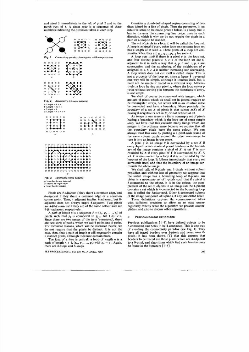
and pixel 3 immediately to the left of pixel 2 and to thenorth-west of p . A chain code is a sequence of thesenumbers indicating the direction taken at each step.
Consider a dumb-bell-shaped region consisting of twodiscs joine d by a line of pixels. Then the perimeter, in anintuitive sense to be made precise below, is a loop, but ithas to traverse the connecting line twice, once in each
0 0 0 0 0 0 0 0 0 0
0 0 0 0 0 0 0 0 0 0
Fig. 1 Connectivity paradox showing two valid interpretations
0 0 0 0 0
0 0 0
0 0 0 0 0 ea b
0 0 0 0 0
C d
Fig. 2a Length = 8 + 4b Length = 12 + 1e Length = 4d Length = 4 + 4 + 4
Assymmetr y in inverse patterns
0 0 0 0 0 0 0 0 0 0 0 0 0
0 0
0 0 0 0 0 0 0
0 0 0 0 0 0
a b
0 0 0 0 0 0 0 0 0 0 0 0 0 0 0 0
0
0
0 0
0 0
0 0 0 0 0 0 0 0 0 0 0 0 0 0 0 0
C
Fig. 3 Incorrectly traced patternsLI Inner border not detectedb Should be single objecte Inner border masked
Pixels are 4-adjacent if they sha re a common edge, and8-adjacent if they share a common edge or a commoncorner point. Thus, Cadjacen t implies 8-adjacent, but 8-adjacent does not always imply Cadjacent. Two pixelsare 4-(8-)connected if they are of the same colour and are4-(8-) adjacent, respectively.
A path of length n is a sequence P = ( p l ,p 2 , . . ., pJ ofpixels such that p i is connected to p i + l for 1 < i < n.Since there are two senses of the term ‘connected’, thereare two sorts of paths, which we call 4-paths and 8-paths.For technical reasons, which will be discussed below, wedo not require that the pixels be distinct. It is not thecase, then, that a path of length n will necessarily conta inn distinct pixels, although it cannot contain more.
The idea of a loop is central: a loop of length n is apath of length n + 1, ( P o , p l , . . ., p.) with p o = p l . Again,there are 4-loops and 8-loops.
IEE PROCEEDINGS- I , Vol. 139, No . 2 , APR IL 1992
direction, which is why we do-not require the pixels in apath or a loop to be distinct.
The set of pixels in a loop L will be called the loop set.A loop is minimal if every other l oop on the same loop sethas a length of at least n. Three pixels of a loop are con-secutive when they are P k , pt + 1, p k + * for some k.
A loop cuts itself if there is a pixel p in the loop set,and four distinct pixels a, b, c , d of the loop set are 8-adjacent to it in such a way that a, p , b and c, p, d areconsecutive, and the numbering of the neighbours of passigned to a, b, c, d is neither increasing nor decreasing.A loop which does not cut itself is called simple. This isnot a prope rty of the loop set, since a figure 8 traversedone way will be simple, although it touches itself, but itneed not be simple if traced in a d ifferent way. Alterna-tively, a loop having any pixel p, where the loop enters ptwice without leaving p in between the directions of entry,is not simple.
We shall of course be concerned with images, whichare sets of pixels which we shall not in general require tobe rectangular arrays, but which will in an intuitive sensebe connected and have a boundary. More precisely, theboundary of a set X of pixels is that subset B ( X ) of Xhaving 8-neighbours not in X, or n ot defined at all.
An image in ou r sense is a finite nonempty set of pixelshaving a bounda ry which is the loop set of some simpleloop. We have that this excludes many things which areimages in the ordinary sense because we require t hat allthe boundary pixels have the same colour. We canalways treat this case by pu tting a 1-pixel-wide frame ofthe same colour pixels around the other non-image toturn it into an image in our sense.
A pixel p in an image 0 is surrounded by a set X ifevery 4-path which starts at p and finishes on the bound-ary of the image contains a pixel of X. A set Y is sur-rounded by X if every pixel of Y is surrounded by X. Aset Y is surroun ded by a loop if it is surrounded by theloop set of the loop. It follows immediately that every setsurrounds itself, and th at the boundar y of an image sur-rounds the whole image.
We shall talk of 0-pixels and 1-pixels without colou rprejudice, and without loss of generality we suppose thatthe initial image has a bounding loop of 0-pixels. Anobject is a nonempty set of 1-pixels such th at if a pixel is8-connected to the object, it is in the object; the com-plement of the set of objects in an image (all the 1-pixels)contains a set which is 4-connected to t he bound ing loopand is called the background. Other 8-connected subsetsof the image composed of 0-pixels, if any, are called holes.
These definitions capture the common-sense ideaswith sufficient precision to allow us to state unam-biguously exactly what the algorithm we provide accom-plishes, and also to discuss other algorithms.
3 Previous border definitions
Previous publications [l-41 have defined objects to be8-connected and holes to be 4-connected. This is one wayof avoiding the connectivity parado x (see Fig. 1). Theyhave all traced borders over 1-pixels and never over 0-pixels; it has been shown [l] that this ensures thatborders to be traced are those pixels which are 4-adjacentto a 0-pixel, and algorithms which find such borders maybe found in the literature [l-41.
207
8/7/2019 border haig
http://slidepdf.com/reader/full/border-haig 3/6
3.1 Problems with previous methodsBorders surrounding solids are traced successfully by themethods mentioned above, but hole borders are frequent-ly poorly formed and may follow suboptimal paths. InFig. 2 we have offset the borders for clarity. The pixels onthe left are colour complements of those on the right, butthe border shapes are very different, the hole bordersbeing longer and more numerous. Moreover, the algo-rithm s of References 1 and 4 failed to tra ce correctly theborders of the patterns shown in Fig. 3. See Reference 6for other examples of incorrectly traced patterns.
4 Proposed new method
4.1 OutlineThe alg orithm we offer uses a different way of avoidingthe connectivity paradox and restores invariance of theresults under change of colour. The border of an object istraced over 1-pixels and over holes over 0-pixels. Allpixels are 8-connected in either case, but loops are notpermitted to cut themselves. Ensuring that this can becarried out for all possible images breaks down into twoparts: first we need to show that an object always has anexternal bounding loop with the properties that it doesnot cut itself (although it may touch itself), and that itsurrounds the object. We call this the rim border. We canapply this to all the (disjoint) objects in an image. Thesecond part consists, in effect, of pairing off the rim
borders and all the pixels 4-connected to them, invertingthe colours, and showing that the result is a disjoint set of(negatived) subimages on which the process can berepeated until the residue is empty. Our procedure will beas follows: first we define the terms rim and rim border,and the floodfill and paring operations. This is done sothat there is invariance under colour alternation. Weshow that every object has a unique rim border. Thecritical result is then a constructive proof that every rimborder is the loop set of a minimal loop which is uniqueto starting point. This is the algorithm for finding the rimborder of an object. The only complications arise fromthe need to ensure that the resulting loop does not cutitself. Finally, we show tha t pa ring an image yields a dis-joint set of subimages of the empty set, enabling therecursion. This completes the description of the algo-rithm and the proof of its correctness; the remainder ofthe paper discusses the implementation and results.
4.2 PreliminariesFor any nonempty set X of pixels, the rim of X, R ( X ) ,isthe set intersection of all subsets of X that surround X.Since X surrounds X, R ( X ) always exists and is non-empty and it is clearly unique. Intuitively, it is the outsideborder of X.
For any pixel p in an image 0, thefloodfill of p,ff l (p) ,isthe set of all those pixels which are connected to p by a4-path. F rom the definition of ‘connected‘ it follows thatevery pixel infl(p) has the same colour as p . If X is anysubset of 0 having pixels of all the same colour, th en thefloodfill of X, f l ( X ) ,is the union of the sets fl(p) for all pin X . It is immediate that f l [ f l ( X ) ]= f f l ( X ) , that X is asubset of ff l(X),and that f l ( X ) is the set union of all 4-connected sets containing X.
Paring is an operatio n applied to images or objects. If0 is an image then it has, by definition, a boundary whichis the loop set of some simple loop, L e . We take the setdifference 0 - f l ( L e ) ; that is we excise from 0 all thosepixels 4-connected to the boundary of 0. We then colour-
208
invert this set, all 0-pixels become 1-pixels and vice versa,the resulting set being written P(0) . It is clear that thisopera tion is well defined. We shall show below that theresult of performing this operation gives a set which iseither empty or is the union of some finite number ofsubimages, where a subimage is a subset that is an image.This is the result which enables the recursion step.
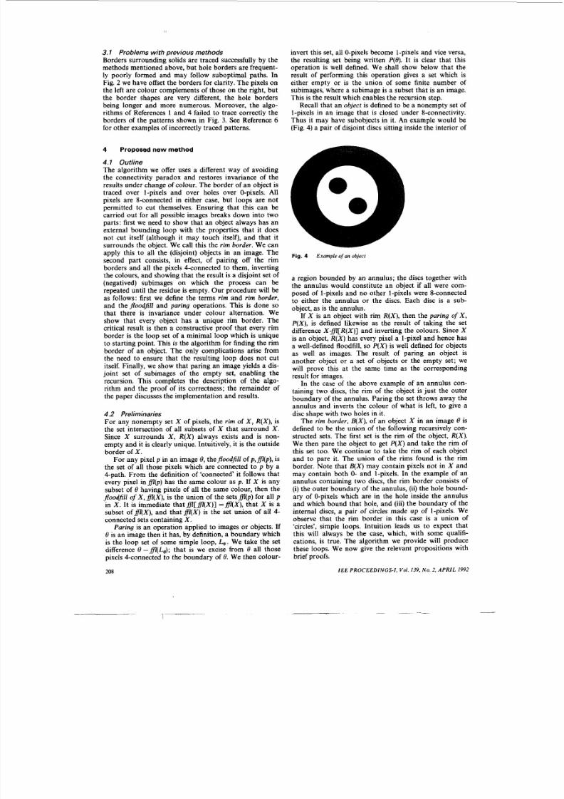
Recall that an object is defined to be a nonempty set of1-pixels in an image that is closed under 8-connectivity.Thus it may have subobjects in it. An example would be(Fig. 4) a pair of disjoint discs sitting inside the interior of
Fig. 4 Example ofan object
a region bounded by an annulus; the discs together withthe ann ulus would const itute an object if all were com-posed of 1-pixels and no other 1-pixels were 8-connectedto either the annulus or the discs. Each disc is a sub-object, as is the annulus.
If X is an object with rim R ( X ) ,then the paring of X,P ( X ) , is defined likewise as the result of taking the setdifference X - f l [ R ( X ) ]and inverting the colours. Since Xis an object, R ( X )has every pixel a 1-pixel and hence hasa well-defined floodfill, so P ( X )is well defined for objectsas well as images. The result of paring an object isanother object or a set of objects or the empty set; wewill prove this at the same time as the correspondingresult for images.
In the case of the above example of an annulus con-taining two discs, the rim of the object is just the outerboundary of the annulus. Paring the set throws away theannulus and inverts the colour of what is left, to give adisc shape with two holes in it.
The rim border, B ( X ) ,of an object X in an image 8 isdefined to be the union of the following recursively con-structed sets. The first set is the rim of the object, R ( X ) .We then pare the object to get P ( X )and take the rim ofthis set too. We continue to take the rim of each objectand to pare it. The union of the rims found is the rimborder. Note that B ( X )may contain pixels not in X andmay contain both 0- and I-pixels. In the example of anannulus containing two discs, the rim border consists of(i) the out er boundary of the annulus, (ii) the hole bound-ary of 0-pixels which are in the hole inside the annulusand which bound that hole, and (iii) the boundary of theinternal discs, a pair of circles made up of 1-pixels. Weobserve that the rim border in this case is a union of‘circles’, simple loops. Intuition leads us to expect thatthis will always be the case, which, with some qualifi-cations, is true. The algorithm we provide will producethese loops. We now give the relevant propositions withbrief proofs.
IEE PROCEEDINGS- I , Vo l . 139, N o . 2, A P R I L 1992
8/7/2019 border haig
http://slidepdf.com/reader/full/border-haig 4/6
8/7/2019 border haig
http://slidepdf.com/reader/full/border-haig 5/6
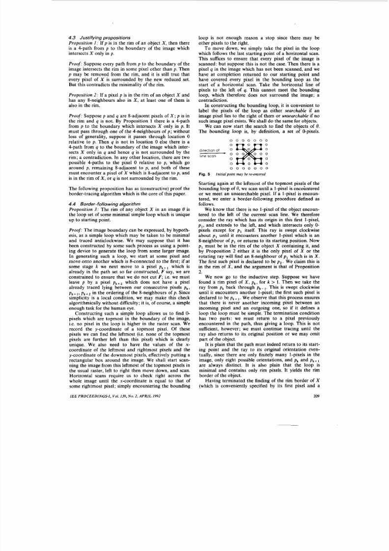
since there'may be other objects to the right of the foundobject. The same procedure is implemented on encoun-tering another 1-pixel unless that pixel is one already inthe rim border of an earlier object. This may be doneconveniently by finding the topmost, leftmost, downmostand rightmost elements of the rim border of X and label-ling the pixels as searchable or unsearchable in the samesense as for the image, except that now we do it on 1-pixels.
On completing a horizontal scan by encountering anunsearchable boundary pixel, we return to the last pixelof the bounding loop of 8 used as a scan start, and takethe next loop pixel to be ou r next scan start. A 1-pixelwhich is found may be checked to see if it is the boundingloop of a rim border found higher u p; if so we jump allthe 1-pixels until a 1-pixel in the boundary labelled asunsearchable is encountered, and then we restart thehorizontal scan from the @pixel to its right. This ensuresthat we do not start tracing the rim border of objectsentirely surrounded by the outer object. It is plain thatthis procedure will give a simple minimal loop which hasloop-set the rim border of the object X; moreover, everysuch object X must be found by the scanning procedurewhich calls the border-following procedure for X. Weobserve that the objects are disjoint since they are closedunder 8-connectivity.
4. 5 The induction stepProposition 4 : The result of paring an image 8 is a setwhich is either empty or the finite union of disjointimages, and the result of paring an object is that it isempty or a finite union of disjoint objects.
Proof: To take the trivial case first, if a n image contain sno objects, then it must consist of only 0-pixels andparing it will yield the empty set. So we may take it thatthere is at least one object X in 8. Paring removes all the0-pixels in the background, which leaves everythinginside the rim border of the (disjoint) set of objects. LetH ( X ) denote the hull of the object X, i.e. the set of allpixels surrounded by the rim of X. Since the objects areclosed under 8-connections, the complement of the unionof the hulls is 4-connected and must therefore be thefloodfill of the boundary of 8. Paring first removes thiscomplement, giving a union of the hulls, which are also
disjoint. Each hull is then colour-inverted. The rim ofeach hull is, by Proposition 3, the loop set of a simpleminimal loop and is hence an image.
If X is an object, the same argument holds by colourinversion.
Proposition 5: The rim border of an object in an imagesuffices to reconstruct the object.
Proof: Recall that the rim border is constructed bytaking the union of the rim of an object, then paring andtaking the rim of the result, which process is iterated untilthe result is empty. Th is yields a set of chain codes for therim loops and some pixels on each such loop, the coloursof the pixels alternating as we move into the object andits holes. To reconstruct the object, we start with the out-ermost loop and floodfill with the loop's colour. The onlyobstruction is any internal loop, which is precisely the
rim border of a hole. Clearly all the floodfilled pixelsreturn to the correct colour. This is now iterated with theappropriate colour change from the rim border of theholes.
210
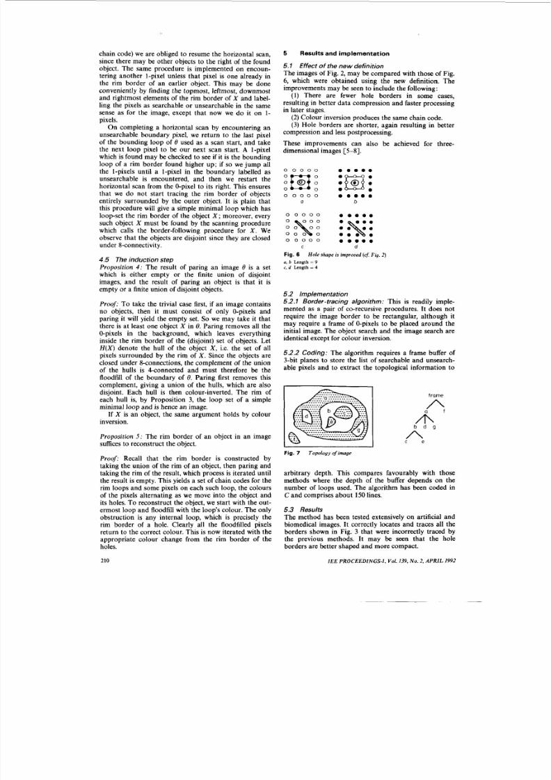
5.1 Effect of the new definitionThe images of Fig. 2, may be compared with those of Fig.6, which were obtained using the new definition. Theimprovements may be seen to include the following:
(1) There are fewer hole borders in some cases,resulting in better data compression and faster processingin later stages.
(2) Colour inversion produces the same chain code.(3) Hole borde rs are sho rter, again resulting in better
compression and less postprocessing.
These improvements can also be achieved for three-dimensional images [S-81.
0 0 0 0 0 e e m e m
0 e0 0 0 0 0 e e e e e
a b
0 0 0 0 0 e e e e m
o o o o o e e e e eC d
Fig. 6
a. b Length=
9e. d Length = 4
Hole shape is improved (cf Fig. 2)
5.2 Implementation5.2.1 Border-tracing algorithm: This is readily imple-mented as a pair of co-recursive procedures. It does notrequire the image border to be rectangular, although itmay require a frame of 0-pixels to be placed around theinitial image. The object search and the image search areidentical except for colour inversion.
52.2 Coding: The algorithm requires a frame buffer of3-bit planes to store the list of searchable and unsearch-able pixels and to extract the topological information to
Fig. 7 Topology of image
arbitrary depth. This compares favourably with thosemethods where the depth of the buffer depends on thenumber of loops used. The algorithm has been coded inC and comprises about 150 lines.
5.3 ResultsThe method has been tested extensively on artificial and
biomedical images. It correctly locates and traces all theborders shown in Fig. 3 that were incorrectly traced bythe previous methods. It may be seen that the holeborders are better shaped and more compact.
I EE P R O C E E D I N G S - I ,Vol. 139, No . 2, A P R I L I992

8/7/2019 border haig
http://slidepdf.com/reader/full/border-haig 6/6
6 Acknowledgments
The authors wish to express their gratitude to Mr. IanMorris of the Queen Elizabeth Medical Centre for sup-plying the magnetic resonance images used in this work.We also wish to thank Mr. Khanh Ly for valuable dis-cussions and providing code for other algorithms usedfor comparisons. This work was supported by an Aus-tralian Commonwealth Postgraduate Research Award,and by a research grant from The University of WesternAustralia.
7 References
1 ROSENFELD, A., and KAK, A.C.: ‘Digital picture processing’(Academic Press, New York, 1982,2nd edn.), Vol. 2
IEE PROCEEDINGS- I , Vol. 139, N o . 2, A P R I L 1992
2 PAVLIDIS, T.: ‘Algorithms for graphics and image processing’(Springer-Verlag, Computer Science Press, MD, 1982)
3 SUZUKI, S., and ABE, K.: ‘Topological structural analysis of digitalbinary image by border following’, Comput. Graphics Image Process.,1985,Jo. pp. 32-46
4 LY, K., and AlTIKIOUZEL, Y.: ‘Contour tracing of biomedicalbinary images’, Proc. Int . Symp. Signal Process., 1987,2,pp. 735-739
5 KRUSE, B.: ‘A fast stack-based algorithm for region extraction inbinary and nonbinary images’ in ‘Signal processing theories andapplications’ (North-Holland Publishing Co., Amsterdam, 1980)
6 DANIELSSON, P.-E.: ‘An improved segmentation and coding algo-rithm for binary and nonbinary images’, IB M J. Res. Den, 1982, 26 ,pp. 698-707
7 TORIWAKI, J . 4 , and YOKOI, S.: ‘Algorithms for skeletonizingthree dimensional digitized binary pictures’, Proc. SPIE, 1983, 435,pp. 2-91
8 CHE N, B.-D., and SIY, P.: ‘Forward/backward conto ur tracing withfeedback’, IEEE Trans. , 1987, PAMI-9, (3), pp. 438-446
211