Embed Size (px)
Citation preview
© 2016 Electric Power Research Institute, Inc. All rights reserved.
Bret FlesnerSr. Technical Leader, NDE Innovation
International Light Water Reactor Materials Reliability Conference and Exhibition
August 2016
BWR Instrument Penetration J-Groove Weld Examinations
NDE Development & On-site Examination Results
2© 2016 Electric Power Research Institute, Inc. All rights reserved.
Contents
2012 N11B instrument nozzle eventN11B fabrication historyBWRVIP Inspection Focus Group actions
– NDE mock-up design and fabrication– Manual phased array technique developmentOn-site examination results
3© 2016 Electric Power Research Institute, Inc. All rights reserved.
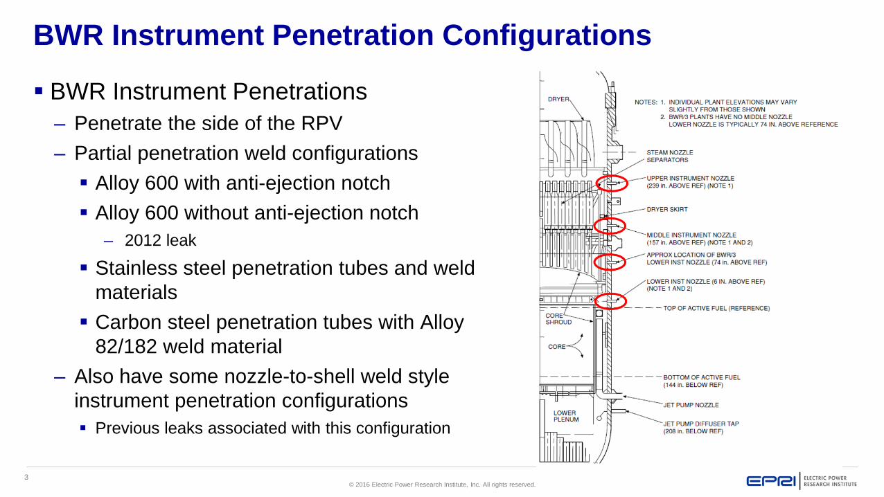
BWR Instrument Penetration Configurations
BWR Instrument Penetrations– Penetrate the side of the RPV– Partial penetration weld configurations Alloy 600 with anti-ejection notch Alloy 600 without anti-ejection notch
– 2012 leak
Stainless steel penetration tubes and weld materials Carbon steel penetration tubes with Alloy
82/182 weld material– Also have some nozzle-to-shell weld style
instrument penetration configurations Previous leaks associated with this configuration
4© 2016 Electric Power Research Institute, Inc. All rights reserved.
Summary of N11B Event and Fabrication Records Review
5© 2016 Electric Power Research Institute, Inc. All rights reserved.
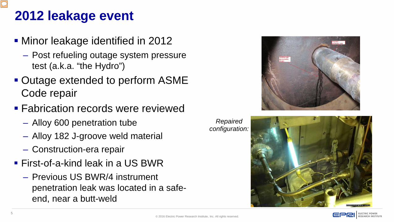
2012 leakage event
Minor leakage identified in 2012– Post refueling outage system pressure
test (a.k.a. “the Hydro”) Outage extended to perform ASME
Code repair Fabrication records were reviewed
– Alloy 600 penetration tube– Alloy 182 J-groove weld material– Construction-era repair
First-of-a-kind leak in a US BWR– Previous US BWR/4 instrument
penetration leak was located in a safe-end, near a butt-weld
Repaired configuration:
6© 2016 Electric Power Research Institute, Inc. All rights reserved.
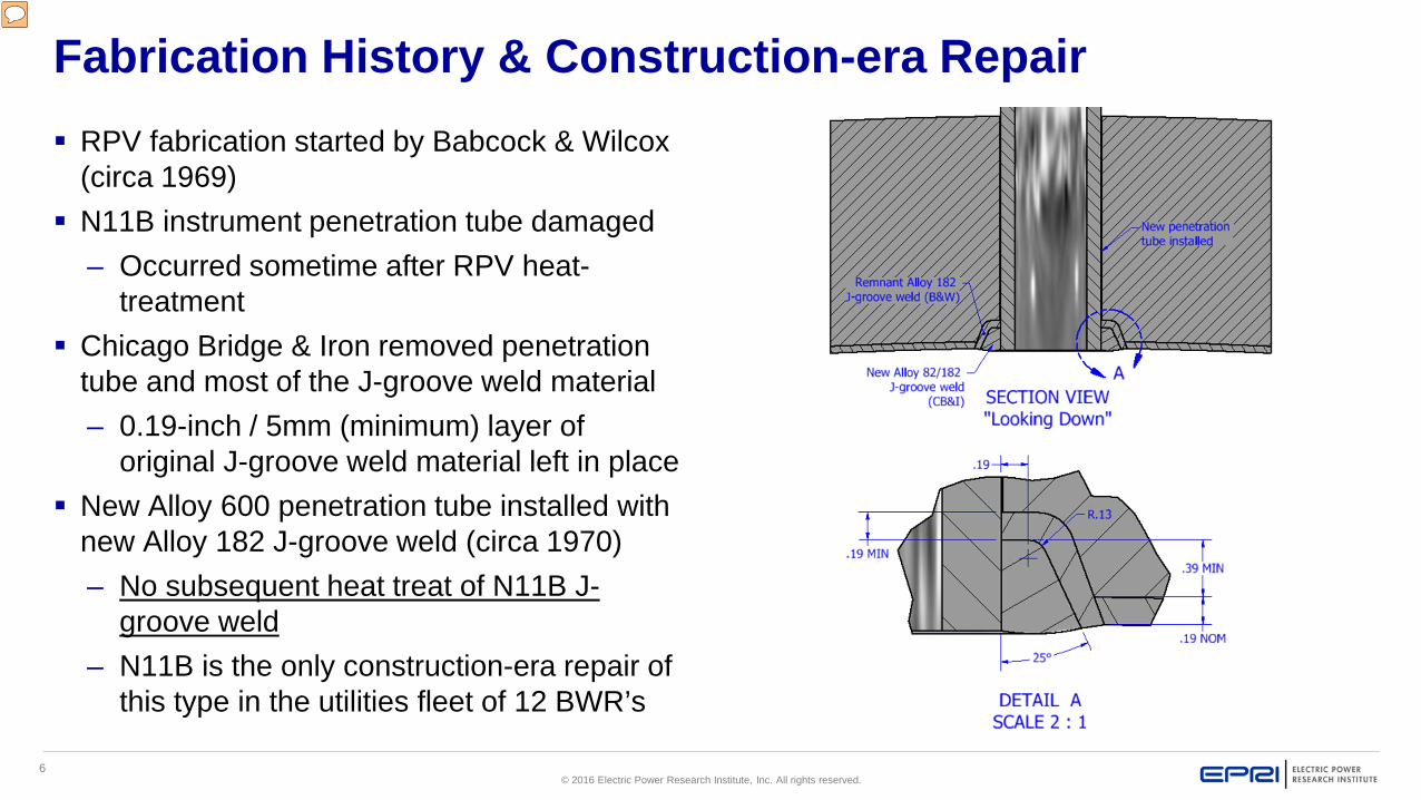
Fabrication History & Construction-era Repair RPV fabrication started by Babcock & Wilcox
(circa 1969) N11B instrument penetration tube damaged
– Occurred sometime after RPV heat-treatment
Chicago Bridge & Iron removed penetration tube and most of the J-groove weld material– 0.19-inch / 5mm (minimum) layer of
original J-groove weld material left in place New Alloy 600 penetration tube installed with
new Alloy 182 J-groove weld (circa 1970)– No subsequent heat treat of N11B J-
groove weld– N11B is the only construction-era repair of
this type in the utilities fleet of 12 BWR’s
7© 2016 Electric Power Research Institute, Inc. All rights reserved.
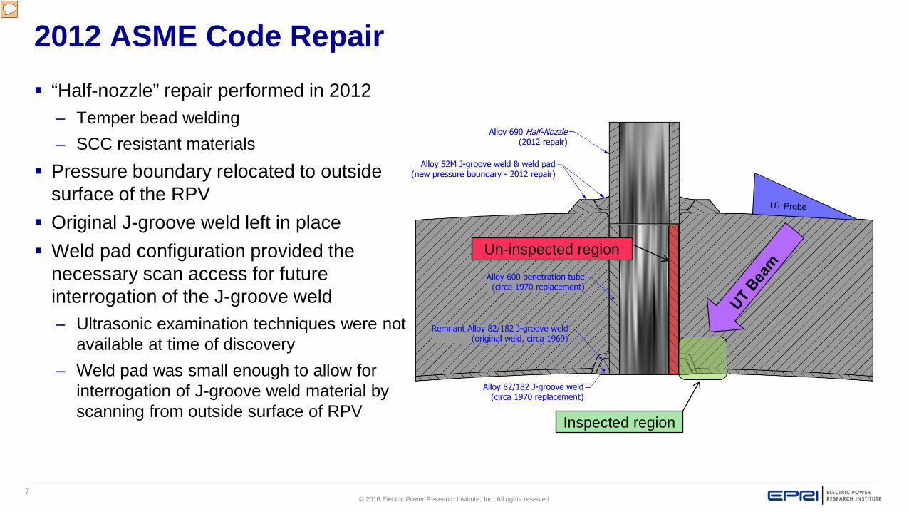
2012 ASME Code Repair “Half-nozzle” repair performed in 2012
– Temper bead welding– SCC resistant materials
Pressure boundary relocated to outside surface of the RPV
Original J-groove weld left in place Weld pad configuration provided the
necessary scan access for future interrogation of the J-groove weld– Ultrasonic examination techniques were not
available at time of discovery– Weld pad was small enough to allow for
interrogation of J-groove weld material by scanning from outside surface of RPV
Inspected region
Un-inspected region
8© 2016 Electric Power Research Institute, Inc. All rights reserved.
BWRVIP NDE Development Activities
9© 2016 Electric Power Research Institute, Inc. All rights reserved.
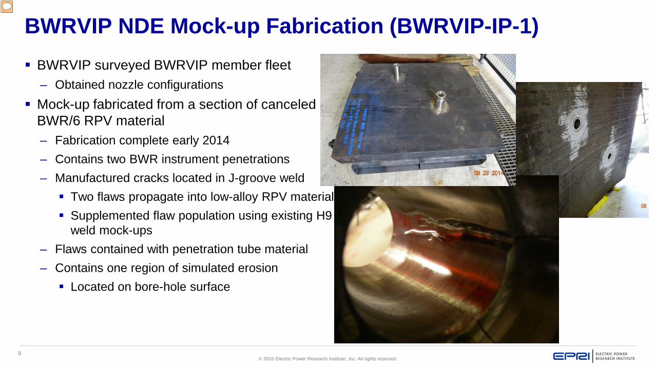
BWRVIP NDE Mock-up Fabrication (BWRVIP-IP-1) BWRVIP surveyed BWRVIP member fleet
– Obtained nozzle configurations Mock-up fabricated from a section of canceled
BWR/6 RPV material– Fabrication complete early 2014– Contains two BWR instrument penetrations– Manufactured cracks located in J-groove weld Two flaws propagate into low-alloy RPV material Supplemented flaw population using existing H9
weld mock-ups– Flaws contained with penetration tube material– Contains one region of simulated erosion Located on bore-hole surface
10© 2016 Electric Power Research Institute, Inc. All rights reserved.
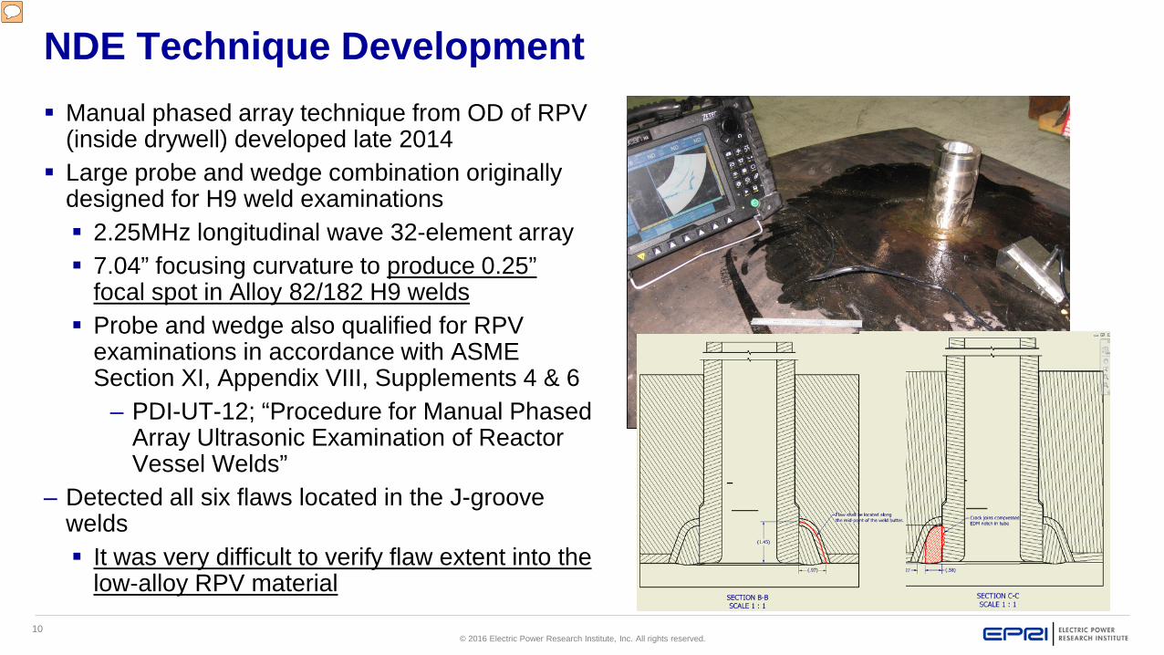
NDE Technique Development Manual phased array technique from OD of RPV
(inside drywell) developed late 2014 Large probe and wedge combination originally
designed for H9 weld examinations 2.25MHz longitudinal wave 32-element array 7.04” focusing curvature to produce 0.25”
focal spot in Alloy 82/182 H9 welds Probe and wedge also qualified for RPV
examinations in accordance with ASME Section XI, Appendix VIII, Supplements 4 & 6
– PDI-UT-12; “Procedure for Manual Phased Array Ultrasonic Examination of Reactor Vessel Welds”
– Detected all six flaws located in the J-groove welds It was very difficult to verify flaw extent into the
low-alloy RPV material
11© 2016 Electric Power Research Institute, Inc. All rights reserved.
NDE Technique Development
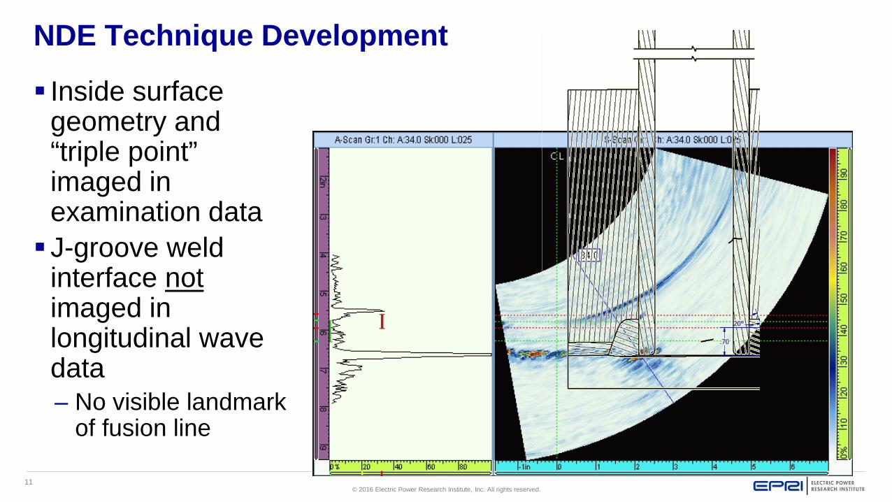
Inside surface geometry and “triple point” imaged in examination data J-groove weld
interface notimaged in longitudinal wave data– No visible landmark
of fusion line
12© 2016 Electric Power Research Institute, Inc. All rights reserved.
NDE Technique Development
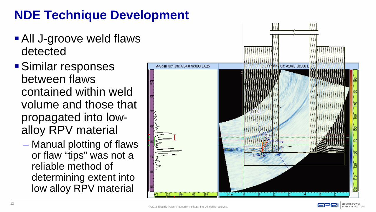
All J-groove weld flaws detectedSimilar responses
between flaws contained within weld volume and those that propagated into low-alloy RPV material– Manual plotting of flaws
or flaw “tips” was not a reliable method of determining extent into low alloy RPV material
13© 2016 Electric Power Research Institute, Inc. All rights reserved.
NDE Technique Development (Supplemental Technique)
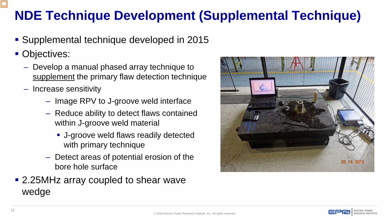
Supplemental technique developed in 2015 Objectives:
– Develop a manual phased array technique to supplement the primary flaw detection technique
– Increase sensitivity– Image RPV to J-groove weld interface– Reduce ability to detect flaws contained
within J-groove weld material J-groove weld flaws readily detected
with primary technique– Detect areas of potential erosion of the
bore hole surface
2.25MHz array coupled to shear wave wedge
14© 2016 Electric Power Research Institute, Inc. All rights reserved.
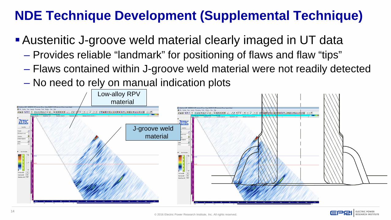
NDE Technique Development (Supplemental Technique)
Austenitic J-groove weld material clearly imaged in UT data– Provides reliable “landmark” for positioning of flaws and flaw “tips”– Flaws contained within J-groove weld material were not readily detected– No need to rely on manual indication plots
Low-alloy RPV material
J-groove weld material
15© 2016 Electric Power Research Institute, Inc. All rights reserved.
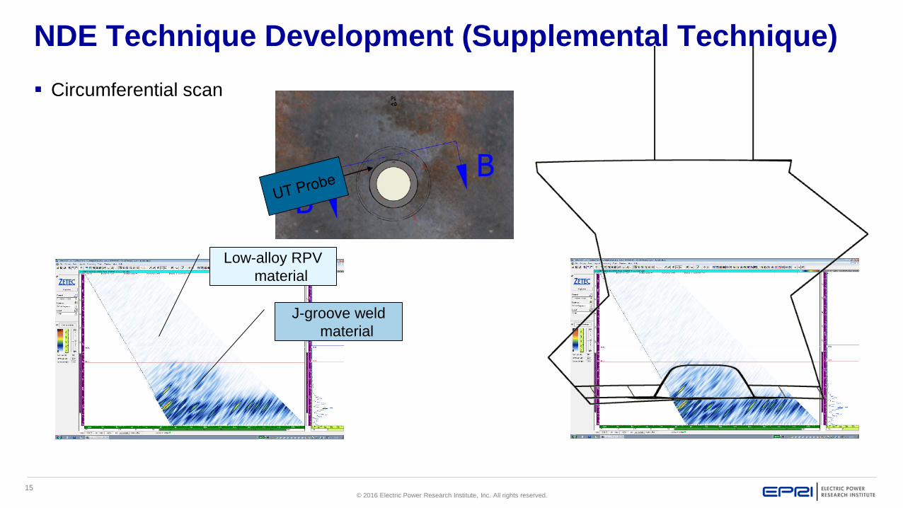
NDE Technique Development (Supplemental Technique) Circumferential scan
Low-alloy RPV material
J-groove weld material
16© 2016 Electric Power Research Institute, Inc. All rights reserved.
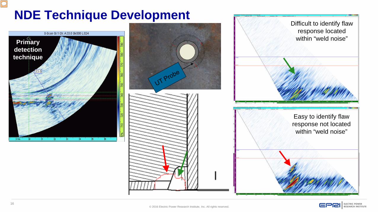
NDE Technique DevelopmentDifficult to identify flaw
response located within “weld noise”
Easy to identify flaw response not located within “weld noise”
Primary detection technique
17© 2016 Electric Power Research Institute, Inc. All rights reserved.
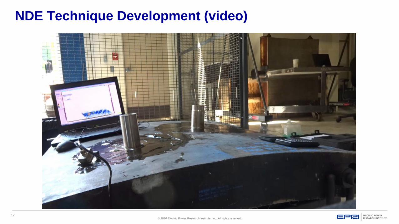
NDE Technique Development (video)
18© 2016 Electric Power Research Institute, Inc. All rights reserved.
On-Site Examination
19© 2016 Electric Power Research Institute, Inc. All rights reserved.
On-Site Examination
Inspection vendor contracted to perform an ultrasonic examination– Primary objective: verify no flaws are present in the low-alloy RPV
material surrounding the J-groove weld – Secondary objective: Determine if flaw is located within J-groove
weld material (for BWR fleet knowledge)Not identifying a flaw would be an indicator that the flaw is
contained within penetration tube material Inspection vendor completed procedure demonstration at
EPRI during January & February 2016
20© 2016 Electric Power Research Institute, Inc. All rights reserved.
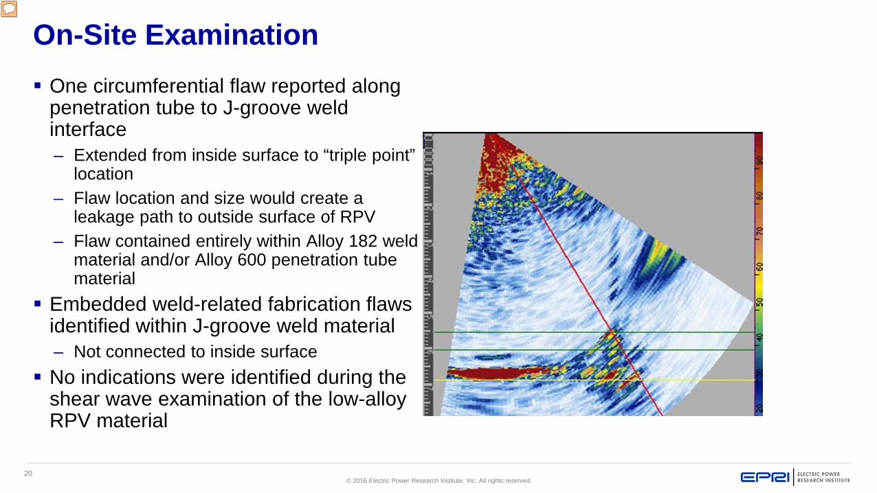
On-Site Examination One circumferential flaw reported along
penetration tube to J-groove weld interface– Extended from inside surface to “triple point”
location– Flaw location and size would create a
leakage path to outside surface of RPV– Flaw contained entirely within Alloy 182 weld
material and/or Alloy 600 penetration tube material
Embedded weld-related fabrication flaws identified within J-groove weld material– Not connected to inside surface
No indications were identified during the shear wave examination of the low-alloy RPV material
21© 2016 Electric Power Research Institute, Inc. All rights reserved.
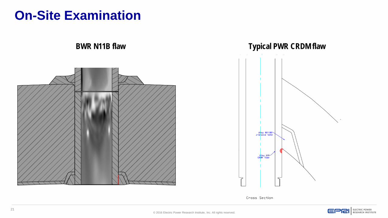
On-Site Examination
BWR N11B flaw Typical PWR CRDM flaw
22© 2016 Electric Power Research Institute, Inc. All rights reserved.
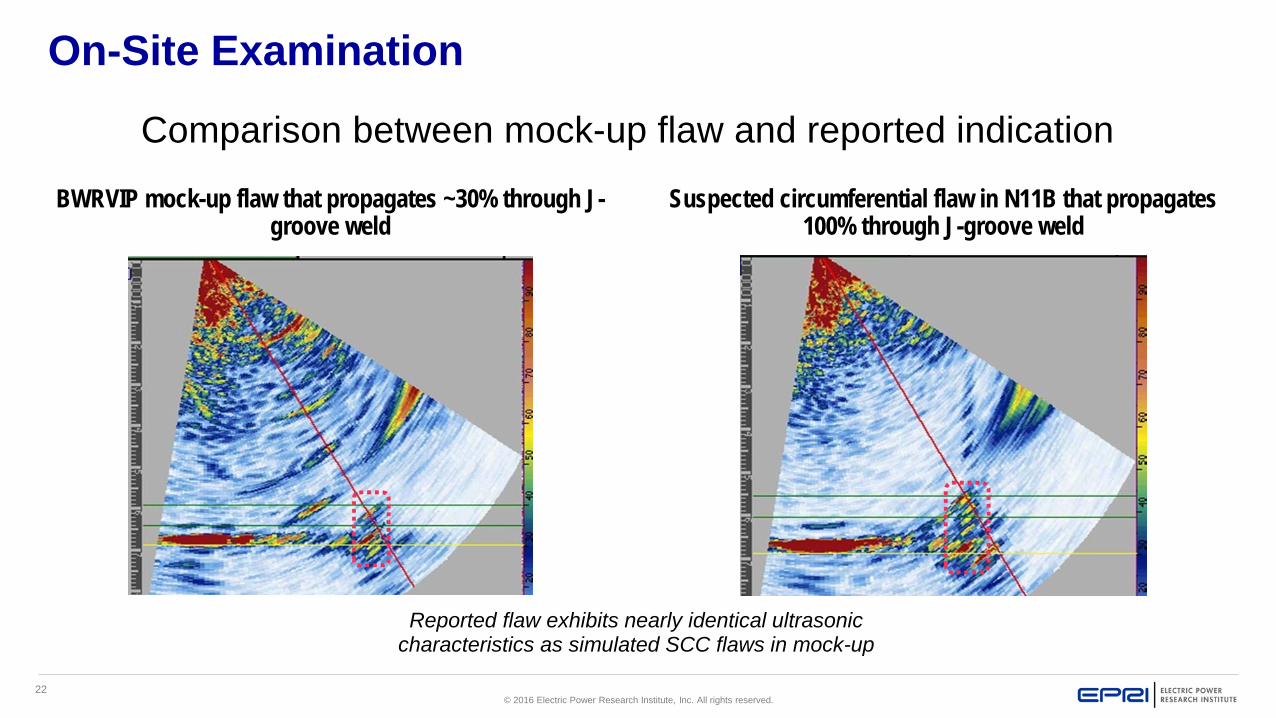
On-Site Examination
BWRVIP mock-up flaw that propagates ~30% through J-groove weld
Suspected circumferential flaw in N11B that propagates 100% through J-groove weld
Reported flaw exhibits nearly identical ultrasonic characteristics as simulated SCC flaws in mock-up
Comparison between mock-up flaw and reported indication
23© 2016 Electric Power Research Institute, Inc. All rights reserved.
Conclusions
The demonstrated examination procedure worked well– Geometric and metallurgical responses were nearly identical between
BWRVIP mock-up scan and on-site examination = Good on-site implementation
Planar flaw reported along Alloy 600 penetration tube – to – Alloy 182 J-groove weld interface– Relief request being prepared using the UT results as a basis coupled
with the Linear Elastic Fracture Mechanics (LEFM) analysis that projects 9 years between subsequent exams
Alloy 600 penetration tube material not examined, but identified J-groove weld flaw would create leakage path– Not possible to examine penetration tube material from OD of RPV
surface
24© 2016 Electric Power Research Institute, Inc. All rights reserved.
Conclusions
MRP proposed further development of phased array technique for PWR applications– BMI penetration J-groove welds was selected for initial
development– Probe will need to be smaller– Recommend scanning canceled PWR bottom heads with PWR
optimized probe design before fabrication of NDE mock-ups
25© 2016 Electric Power Research Institute, Inc. All rights reserved.
References Mock-up fabrication and development of
initial flaw detection technique– BWRVIP-282: BWR Vessel and Internals
Project, Nondestructive Evaluation Development 2014. http://www.epri.com/abstracts/Pages/ProductAbstract.aspx?ProductId=000000003002003088
Development of supplemental shear wave technique– BWRVIP-290: BWR Vessel and Internals
Project, Nondestructive Evaluation Development 2015. EPRI, Palo Alto, CA: 2015. 3002005570. http://www.epri.com/abstracts/Pages/ProductAbstract.aspx?ProductId=000000003002005570
NDE Mock-up information, including flaw information– BWRVIP-03 Revision 18, Section 14.14.1,
BWRVIP-IP-1 https://membercenter.epri.com/abstracts/Pages/ProductAbstract.aspx?ProductId=000000003002005571
Inspection vendor demonstration– BWRVIP letter 2016-034 (interim
documentation)– Will be documented in BWRVIP-03 Revision 19
Summary of on-site examination– Will be documented in 2016 NDE Development
Update
26© 2016 Electric Power Research Institute, Inc. All rights reserved.
BWR Instrument Penetration J-Groove Weld Examinations
Questions?
Bret Flesner ([email protected])Jeff Landrum ([email protected]) BWRVIP Inspection Task Manager

27© 2016 Electric Power Research Institute, Inc. All rights reserved.
Together…Shaping the Future of Electricity
28© 2016 Electric Power Research Institute, Inc. All rights reserved.
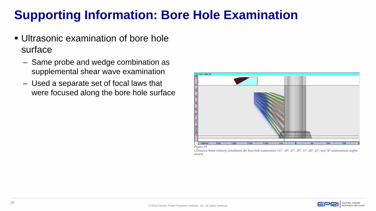
Supporting Information: Bore Hole Examination
Ultrasonic examination of bore hole surface – Same probe and wedge combination as
supplemental shear wave examination– Used a separate set of focal laws that
were focused along the bore hole surface
29© 2016 Electric Power Research Institute, Inc. All rights reserved.
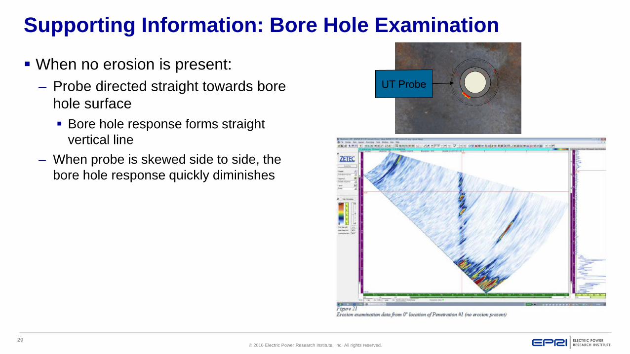
Supporting Information: Bore Hole Examination
When no erosion is present:– Probe directed straight towards bore
hole surface Bore hole response forms straight
vertical line– When probe is skewed side to side, the
bore hole response quickly diminishes
30© 2016 Electric Power Research Institute, Inc. All rights reserved.
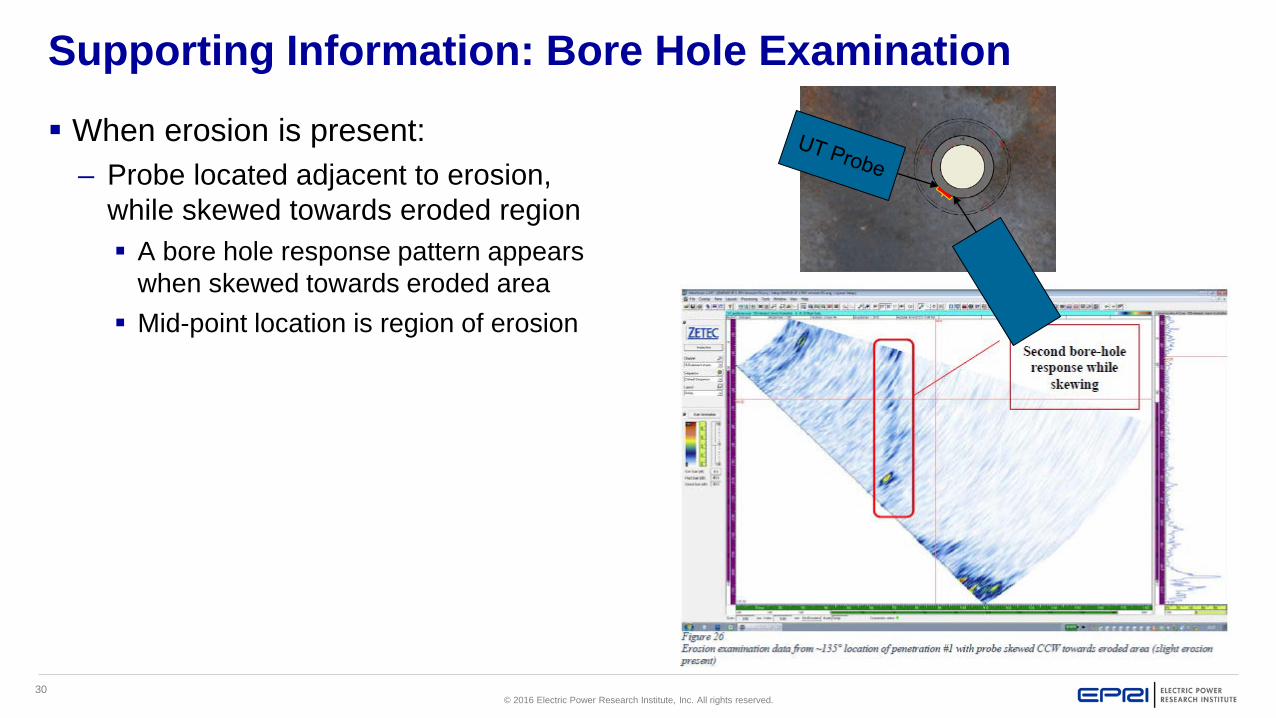
Supporting Information: Bore Hole Examination
When erosion is present:– Probe located adjacent to erosion,
while skewed towards eroded region A bore hole response pattern appears
when skewed towards eroded area Mid-point location is region of erosion
31© 2016 Electric Power Research Institute, Inc. All rights reserved.
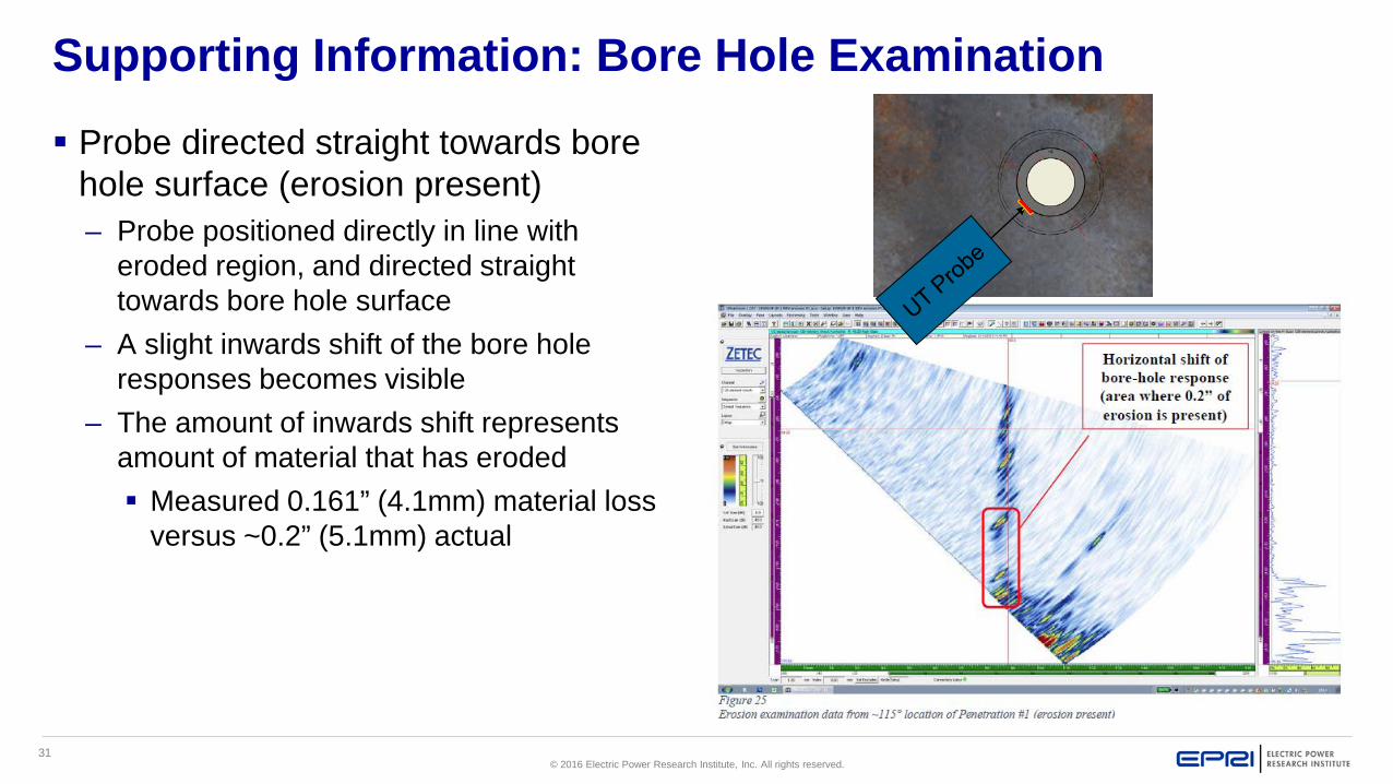
Supporting Information: Bore Hole Examination
Probe directed straight towards bore hole surface (erosion present)– Probe positioned directly in line with
eroded region, and directed straight towards bore hole surface
– A slight inwards shift of the bore hole responses becomes visible
– The amount of inwards shift represents amount of material that has eroded Measured 0.161” (4.1mm) material loss
versus ~0.2” (5.1mm) actual