Embed Size (px)
Citation preview

Contents lists available at ScienceDirect
Case Studies in Thermal Engineering
Case Studies in Thermal Engineering 8 (2016) 94–104
http://d2214-15
E-m
journal homepage: www.elsevier.com/locate/csite
Adaptive Neuro-Fuzzy Inference System of friction factor andheat transfer nanofluid turbulent flow in a heated tube
Adnan Mohammed HusseinAl-Haweeja Institute, Northern Technical University, Iraq
a r t i c l e i n f o
Article history:Received 14 June 2015Received in revised form3 June 2016Accepted 5 June 2016Available online 8 June 2016
Keywords:NanofluidCFDANFISANSYSFLUENT
x.doi.org/10.1016/j.csite.2016.06.0017X/& 2016 Published by Elsevier Ltd.
ail address: [email protected]
a b s t r a c t
In this paper, estimating of hydrodynamics and heat transfer nanofluid flow throughheated tube has been conducted by using Adaptive Neuro-Fuzzy Inference System (AN-FIS). The CFD data related to three types of nanofluids (Al2O3, SiO2 and TiO2) flow inhorizontal tube with 19 mm diameter and 2000 mm length. Heat flux around tube is fixedat 5000 W/m2, the range of Reynolds number is (3000–30,000) and volume concentra-tions are (1% and 2%). ANFIS model has three input data presented by Reynolds number,volume concentration of nanofluids and materials and two output presented predictingfriction factor and Nusselt number in the tube. The simulation results of proposed algo-rithm have been compared with CFD simulator in which the mean relative errors (MRE)are 0.1232% and 0.1123 for friction factor and Nusselt number respectively. Finally, ANFISmodels can predict hydrodynamics and heat transfer of the higher accuracy than thedeveloped correlations.
& 2016 Published by Elsevier Ltd.
1. Introduction
Large wide of world using tube in engineering applications and is significant in practical applications, such as heatexchangers, steam generators, chemical reactors, membrane separations, and piping systems [1]. Recent research has beenfocused on practical tube applications based on emerging both soft computing fields like Computational fluid dynamic(CFD), and computational intelligence such as ANN, GA, PSO, and fuzzy logic [2].
The heat transfer enhancement by used aluminum oxide nanofluid with different volume concentration and constantwall temperature studied experimentally by Sundar and Sharma [3]. It was concluded that the friction factor and heattransfer enhancement by 10% and 40% respectively. The single-phase approach may be used for heat transfer and pressuredrop prediction of new nanofluids. Numerical study of convection flow of a Al2O3-water nanofluid inside the tube underturbulent flow with the wall uniform temperature was presented by Bianco et al. [4]. Their results showed the convectiveheat transfer coefficient for conventional liquid is lower than nanofluids and friction factor data was agreed with experi-mental data of Pak and Cho[5].
Many researchers have introduced different forms of neural-fuzzy networks and its applications in bioinformatics,petroleum engineering and pattern recognition [6–7]. Group of Artificial intelligence methods was used to estimate theconvective heat transfer coefficient and pressure drop during annular flow numerically such as multilayer perceptron (MLP),generalized regression neural network (GRNN) and radial basis networks (RBFN), likewise, the Adaptive Neuro-Fuzzy In-ference System (ANFIS) have been used to decide best approach of heat transfer [8].

Nomenclature
C specific heat capacity [J/kg °C ]D diameter [m]f friction factorh convection heat transfer coefficient [W/m2 °C]k thermal conductivity [W/m °C]n number of runsNu Nusselt Number [h D/k]P Pressure [N/m2]Pr Prandtle Number [C. μ/k]Re Reynolds Number [ρD u/k]u Velocity [m/s]G Response parametersμ Viscosity [N s/m2]
ρ Density [kg/m3]ϕ Volume concentrationANFIS Adaptive Neuro-Fuzzy Inference SystemCFD computational fluid dynamicMR% Maximum ErrorMAE% Mean Average Error
Subscripts
f liquid phasesp solid particlenf nanofluidh hydraulic
A.M. Hussein / Case Studies in Thermal Engineering 8 (2016) 94–104 95
Reynolds number, velocity and flow rate have been used as inputs to estimate friction factor of an open channel flowwith ANFIS by Samandar [9]. Experimental data from the laboratory have been used to learn algorithm and training withANFIS model, in addition, the simulation results of friction factor were compared with experimental results. A good cor-relation was obtained between the experimental data and predicted results of Balcilar et al. [10]. ANFIS is a hybrid schemebased to a combination of neural networks and Fuzzy logic, which is an efficient tool for modeling different kind of un-certainty associated with imprecision and vagueness [6,10–14].
This paper, focus on hydrodynamic and heat transfer under turbulent three types of nanoparticles (Al2O3, SiO2 and TiO2)suspended in water flow in a heated straight tube for two volume concentration 1% and 2% by ANFIS. Firstly, introduce abrief description of a heated tube and its boundary conditions. Secondly, ANFIS with three input parameters and two outputto predict the friction factor and Nusselt number. Finally, the results of proposed algorithm shows it effectiveness comparedwith CFD simulation for different Reynolds number, volume concentrations and materials of nanofluid flow through theheated tube.
2. Theoretical analysis
2.1. Physical model
Fig. 1 shows the test rig as included straight horizontal tube of 19 mm diameter and 2000 mm length with wire heateraround it to fix heat flux at 5000 W/m2. The nanofluid is flowing inside tube with high velocity and Reynolds number range(3000–30,000) so it will gain heat from input to output that taken in this case.
The simulation results are compared to the equations for the friction factor (1) and Nusselt number (2) that correlated byBlasius and Dittus-Boelter respectively [1]:
=( )
fRe
0. 31610.25
= × × ( )Nu Re Pr0. 023 20.8 0.4
These two equations correlated for pure water that used for verification process.The thermal properties of nanofluid were calculated by using the equations below [15]:Density (ρnf ) of nanofluid can be calculating by:
( )ρ φρ φ ρ= + − ( )1 3nf p f
Fig. 1. Schematic of physical model.

A.M. Hussein / Case Studies in Thermal Engineering 8 (2016) 94–10496
Specific heat capacity (Ceff ) of nanofluid can be calculating by:
( )φ ρ φ ρρ
=( ) + − ( )
( )C
C C1
4nf
p f
nf
Thermal conductivity (knf ) of nanofluid as:
φ
φ= +
−
+ − −( )
⎜ ⎟
⎜ ⎟ ⎜ ⎟
⎛⎝
⎞⎠
⎛⎝
⎞⎠
⎛⎝
⎞⎠
k
k1
3 1
2 15
nf
f
k
k
k
k
k
k
p
f
p
f
p
f
Viscosity (μeff ) of nanofluid can be calculated by:
( )μ
μφ φ= + +
( )1 2.5 6.25
6
nf
f
2
where φ is the volume concentration of nanofluid and subscript p, f and nf are referred to solid particles, fluid and nanofluidpart respectively. All properties of fluid (water) have taken from [16].
3. Neuro–fuzzy
3.1. Basic of adaptive neuro-fuzzy
The Adaptive Network Based Fuzzy Inference Systems (ANFIS) is a hybrid type of framework, which learns the rules andmembership functions from data. The ANFIS is a network of nodes and directional links associated with a learning rule forinstance, back propagation learning a relationship between inputs and outputs. Fig. 2 shows the ANFIS configuration inwhich the circular nodes represent fixed nodes and the square nodes are represent parameters nodes that have to be learnt.
For the training of the ANFIS network, there is a forward pass and a backward pass. The forward pass propagates inputvectors through the network layer by layer. In the backward pass, the error is sent back through the network in a similarmanner to back propagation [13].
Layer 1: The output of each node is:O1, i¼mAi(x) for i ¼1, 2.O1, i¼mBi�2(y) for i¼3, 4.So, the O1, i(x) is essentially the membership grade for x and y. The membership functions could be anything but for
illustration purposes we will use the bell shaped function, that is,
μ ( ) =+ ( )
−x
1
1 7
Ax c
a
bi2i
i
where ai, bi, ci are parameters to be known. These are the premise parameters.Layer 2: Every node in this layer is fixed. This is where the t-norm is used to ‘AND’ the membership grades – for example
the product:
μ μ= = ( ) ( ) = ( )O w x y i 1, 2 8i i Ai Bi2,
Fig. 2. Construction of Neuro fuzzy.

Fig. 3. Neuro-fuzzy for heated tube.
A.M. Hussein / Case Studies in Thermal Engineering 8 (2016) 94–104 97
Layer 3: It contains fixed nodes which calculate the ratio of firing strengths of the rules:
= =+
=( )
O ww
w wfor i 1, 2
9i ii
3,1 2
Layer 4: The nodes in this layer are adaptive and perform consequent of the rules:
( )= = + + = ( )O wf w Px q y r for i 1, 2 10i i i i i i i4,
The parameters in this layer (pi, qi, ri) are to be determined and are referred to as the consequent parameters.Layer 5: There is a single node here that computes the overall output:
∑= =∑
∑ ( )=
=
=
O wfwf
w 11i
ii i
i i i
i i5,
1
21
2
12
This is how, typically, the input vector is fed through the network layer by layer.
3.2. Modeling of heated tube
In this study, the neuro-fuzzy systems with the CFD analysis for specified flow regimes in horizontal single-phase flowhas been conducted. Fig. 3 shows effective predicting of output parameters based on a proper selected inputs and outputs ofNeuro-Fuzzy, structure of the network and training of it using appropriate data should be done with almost care.
In the present study, three inputs are selected as Reynolds number (Re), concentration of volume (φ) and nanofluidmaterials; and on another hand the output node representing the friction factor and Nusselt number.
To train ANN models with the results of the CFD, network architecture was required; first the entire training data file wasrandomly divided into training and testing data sets.
About 90% of the data and 55 patterns were used to train the different network architectures and remaining 5 patternswhich used for testing to verify the prediction ability of each training ANFIS model as shown in Table 1.
Numerical studies were conducted to verify the ANFIS model results. Number of CFD data was used in order to improveANFIS model, for training and the remainder for testing performance. The relative error results of ANFIS model are shown inTables 2 and 3, for training data, where the relative error (MR%) for variable G and the mean relative error (MAR%) wereestimated as [9]:
=−
( )MR
G G
G%
12CFD ANFIS
CFD
( )∑=( )=
MAEN
MR%1
%13i
N
i1
Table 1Sample of training data.
Re Volumeconcentration
Materials Fricationfactor
Nusseltnumber
3000 0.01 1 0.2536 536000 0.01 1 0.1976 559000 0.01 1 0.1416 58
12,000 0.01 2 0.0912 6115,000 0.01 2 0.0654 6418,000 0.01 2 0.0553 6721,000 0.01 3 0.0302 7024,000 0.01 3 0.0376 7427,000 0.01 3 0.0351 77

Table 2Ccomparison of ANFIS with CFD of friction factor data.
Re Volume concentration Materials Frication factor CFD Friction factor ANFIS Error %
3000 0.01 1 0.2363 0.2342 0.892133,000 0.01 1 0.0379 0.0376 0.73853000 0.01 2 0.2459 0.2411 1.9608
33,000 0.01 2 0.0380 0.0373 1.73163000 0.01 3 0.2499 0.2465 1.3645
33,000 0.01 3 0.0381 0.0375 1.56313000 0.02 1 0.2375 0.2338 1.5397
33,000 0.02 1 0.0382 0.0379 0.65173000 0.02 2 0.2405 0.2378 1.1292
33,000 0.02 2 0.0385 0.0380 1.33413000 0.02 3 0.2413 0.2387 1.0861
33,000 0.02 3 0.0387 0.0381 1.4433MR 1.2862MAR 0.1232
Time per test 183 s 0.00926 s
Table 3Ccomparison of ANFIS with CFD of Nusselt number data.
Re Volume concentration Materials Nusselt number CFD Nusselt number ANFIS Error %
3000 0.01 1 61 60 1.63934426233,000 0.01 1 70 69 1.4285714293000 0.01 2 67 67 0
33,000 0.01 2 74 73 1.3513513513000 0.01 3 73 72 1.369863014
33,000 0.01 3 83 82 1.2048192773000 0.02 1 81 80 1.234567901
33,000 0.02 1 89 89 03000 0.02 2 85 84 1.176470588
33,000 0.02 2 96 95 1.0416666673000 0.02 3 90 90 0
33,000 0.02 3 108 107 0.925925926MR 0.97477MAR 0.1123
Time per test 183 s 0.00926 s
A.M. Hussein / Case Studies in Thermal Engineering 8 (2016) 94–10498
4. CFD analysis
4.1. Simulation study
ANSYS/FLUENT software is using to simulate governing equations of turbulent forced convection heat transfer in ahorizontal tube with constant heat flux. Computational fluid dynamics (CFD) has the ability to deal with a wide range ofsimulating engineering problems related to heat transfer by means of the numerical solution. The governing equationsincluded continuity, momentum and energy equations [17]:
( )ρ∇⋅ = ( )u. 0 14nf
( ) ( )ρ μ∇⋅ = − ∇ + ∇⋅ ∇ ( )uu P u 15nf nf
( ) ( )ρ∇⋅ = ∇⋅ ∇ ( )C uT k T 16nf nf nf
Equations are solved iteratively using the segregated solver and a pressure correction equation which used to ensure themomentum and mass conservation. A SIMPLE scheme was adopted for the treatment of pressure. Turbulent viscous (k-ε)model was employed. For all simulations performed in this work, converged solutions were considered for residuals lowerthan 1�10�6 for all the governing equations.
The CFD modeling region for heat transfer and fluid flow phenomena in pipes could be done as follows:

Fig. 4. Mesh generated model.
Fig. 5. Grid independent test.
A.M. Hussein / Case Studies in Thermal Engineering 8 (2016) 94–104 99
I. Preprocess stage, the geometry of heated tube region was constructed and computational mesh was generated inGAMBIT. GAMBIT model as shown in Fig. 4, used to describe problem which graph and mesh the section test with sizeof (2000�30) and 2000 with length of pipe, 30 with radius.
II. It followed by the heated tube model, boundary conditions, and other appropriate parameters were defined in modelssetup and solving stage.
III. Finally the results could be obtained by ANSYS/FLUENT iterations which led to converged criteria. The friction factorand Nusselt number through the pipe could be obtained throughout the computational domain in the post-processstage.
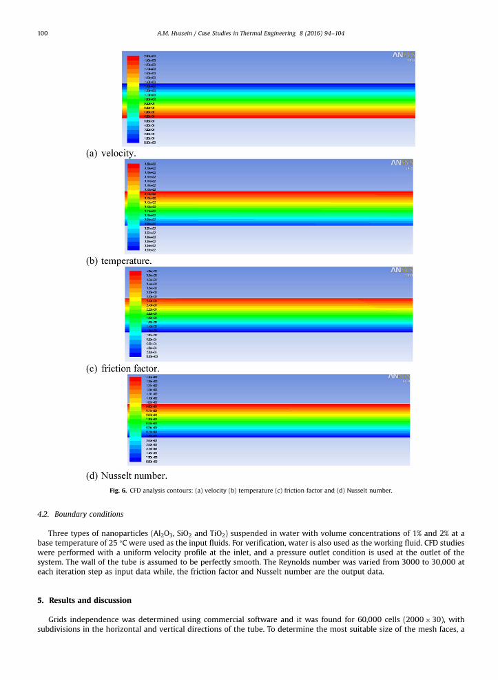
Fig. 6. CFD analysis contours: (a) velocity (b) temperature (c) friction factor and (d) Nusselt number.
A.M. Hussein / Case Studies in Thermal Engineering 8 (2016) 94–104100
4.2. Boundary conditions
Three types of nanoparticles (Al2O3, SiO2 and TiO2) suspended in water with volume concentrations of 1% and 2% at abase temperature of 25 °C were used as the input fluids. For verification, water is also used as the working fluid. CFD studieswere performed with a uniform velocity profile at the inlet, and a pressure outlet condition is used at the outlet of thesystem. The wall of the tube is assumed to be perfectly smooth. The Reynolds number was varied from 3000 to 30,000 ateach iteration step as input data while, the friction factor and Nusselt number are the output data.
5. Results and discussion
Grids independence was determined using commercial software and it was found for 60,000 cells (2000�30), withsubdivisions in the horizontal and vertical directions of the tube. To determine the most suitable size of the mesh faces, a

Fig. 7. CFD data with different Reynolds Number: (a) friction factor, (b) Nusselt number.
A.M. Hussein / Case Studies in Thermal Engineering 8 (2016) 94–104 101
grid independence test was performed for the physical model. In this study, rectangular cells were used to mesh the tube asshown in Fig. 5.
Grid independence was checked using different grid systems, and four mesh sizes were considered, 40,000 cells(2000�20), 60,000 cells (2000�30) and 80,000 cells (2000�40) for pure water. The friction factor and Nusselt numberwere determined for all four mesh sizes, and the results all agreed with each other. All four-mesh sizes could have beenused, and in the study undertaken, the mesh sizes with 60,000 cells was adopted because it was the best in terms ofaccuracy. Similar to the methodology has followed by Hussein et al. [18] to select the optimum mesh size.
The assumption of this study was 1% and 2% nanofluids volume concentration at (25 °C) base temperatures which usedas input fluids. For verification process, water was also employed as working fluid which carried out with uniform velocityprofile at the inlet of the horizontal tube. The pressure outlet boundary condition was used at the outlet boundary. The wallof the pipe was assumed to be perfectly smooth with zero roughness height and a constant wall heat flux (5000 W/m2) aswall boundary.
Fig. 6 shows contour of CFD data of (velocity, temperature, friction factor and Nusselt number) along axisymmetric tubefor pure water. The velocity profile shown in Fig. 6(a) increases with the centerline of tube from zero near the Wall to themáximum value of 2 m/s at the center of tube. Likewise, Fig. 6(b, c and d) shows temperature, friction factor and Nusseltnumber increase with wall side when boundary layer is found till maximum value of 320, 0.004 and 146 respectively.
Fig. 7(a) shows the friction factor against Reynolds number with two concentration of volume for 3 types of nanofluids. It
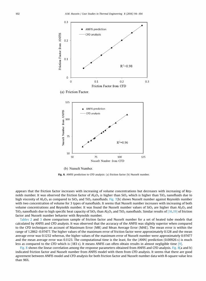
Fig. 8. ANFIS prediction to CFD analysis: (a) friction factor (b) Nusselt number.
A.M. Hussein / Case Studies in Thermal Engineering 8 (2016) 94–104102
appears that the friction factor increases with increasing of volume concentrations but decreases with increasing of Rey-nolds number. It was observed the friction factor of Al2O3 is higher than SiO2 which is higher than TiO2 nanofluids due tohigh viscosity of Al2O3 as compared to SiO2 and TiO2 nanofluids. Fig. 7(b) shows Nusselt number against Reynolds numberwith two concentration of volume for 3 types of nanofluids. It seems that Nusselt number increases with increasing of bothvolume concentrations and Reynolds number. It was found the Nusselt number values of SiO2 are higher than Al2O3 andTiO2 nanofluids due to high specific heat capacity of SiO2 than Al2O3 and TiO2 nanofluids. Similar results of [16,19] of frictionfactor and Nusselt number behavior with Reynolds number.
Tables 2 and 3 show comparison sample of friction factor and Nusselt number for a set of heated tube models thatcalculated by ANFIS and CFD analysis. It was observed that the accuracy of the ANFIS was slightly superior when comparedto the CFD techniques on account of Maximum Error (MR) and Mean Average Error (MAE). The mean error is within therange of 1.2862–0.97477. The higher values of the maximum error of friction factor were approximately 0.128 and the meanaverage error was 0.1232 whereas, the higher values of the maximum error of Nusselt number were approximately 0.97477and the mean average error was 0.1123. The computational time is the least, for the (ANN) prediction (0.00926 s) is muchless as compared to the CFD which is (183 s). It means ANFIS can often obtain results in almost negligible time [9].
Fig. 8 shows the linear correlation among the response parameters obtained from ANFIS and CFD analysis. Fig. 8(a and b)indicated friction factor and Nusselt number from ANFIS model with them from CFD analysis. It seems that there are goodagreement between ANFIS model and CFD analysis for both friction factor and Nusselt number data with R-square value lessthan 96%.

Fig. 9. Validation of CFD data.
A.M. Hussein / Case Studies in Thermal Engineering 8 (2016) 94–104 103
Fig. 9 shows the validation of CFD data with the experimental data of [19–21]. It can be seen the good agreement of bothfriction factor and Nusselt number simulation data against the experimental data with deviation not more than 5%.
6. Conclusions
There are two parts in this article; the first is the numerical study of turbulent nanofluid flow in the circular heated tube.The influence of Reynolds number (Re), nanofluid volume concentration (ϕ) and the nanofluids type on the friction factorand Nusselt number were studied. The second part is included the intelligent study using ANFIS to find friction factor andNusselt number through circular heated tube. It can be concluded that:
1. Friction factor increases with increasing of volume concentrations but decreases with increasing of Reynolds number.2. Nusselt number increases with increasing of both volume concentrations and Reynolds number.3. Al2O3 nanofluid has higher friction factor than SiO2 and TiO2, furthermore, SiO2 nanofluid has higher Nusselt number than
Al2O3 and TiO2.4. ANFIS is completed iterations with (0.00926 s) time but CFD is completed iterations with (183 s), so reducing time by
using ANFIS for the case undertaken.5. The prediction of the friction factor and Nusselt number with the ANFIS models is in good agreement with the CFD
analysis with maximum error of less than 0.1282.

A.M. Hussein / Case Studies in Thermal Engineering 8 (2016) 94–104104
References
[1] S.K. Das, Nanofluids: Science and Technology, John Wiley & Sons, 2007.[2] R. Babuska, Fuzzy Modeling for Control, Kluwer Academic Publishers, 1998.[3] L.S. Sundar, K.V. Sharma, Turbulent heat transfer and friction factor of Al2O3 nanofluid in circular tube with twisted tape inserts, Int. J. Heat Mass
Transf. 53 (7) (2010) 1409–1416.[4] V. Bianco, O. Manca, S. Nardini, Numerical investigation on nanofluids turbulent convection heat transfer inside a circular tube, Int. J. Therm. Sci. 50 (3)
(2011) 341–349.[5] B.C. Pak, Y.I. Cho, Hydrodynamic and heat transfer study of dispersed fluids with submicron metallic oxide particles, Exp. Heat Transf Int. J. 11 (2)
(1998) 151–170.[6] J. Jang, S.R. Rule, Extraction using generalized neural networks. In Proc. of the fourth IFSA World Congress, 1991.[7] N.K. Kasabov, Foundations of Neural Networks (Fuzzy Systems) and Knowledge Engineering, Marcel Alencar, 1996.[8] J.C. Bezdek, Pattern Recognition with Fuzzy Objective Function Algorithms, Kluwer Academic Publishers, 1981.[9] A. Samandar, A model of adaptive neural-based fuzzy inference system (ANFIS) for prediction of friction coefficient in open channel flow, Sci. Res.
Essays 6 (5) (2011) 1020–1027.[10] M. Balcilar, A. Dalkilic, S. Wongwises, Artificial neural network techniques for the determination of condensation heat transfer characteristics during
downward annular flow of R134a inside a vertical smooth tube, Int. Commun. Heat Mass Transfer 38 (1) (2011) 75–84.[11] R. Babuška, H. Verbruggen, Neuro-fuzzy methods for nonlinear system identification, Annu. Rev. Control 27 (1) (2003) 73–85.[12] N.R. Pal, J.C. Bezdek, On cluster validity for the fuzzy c-means model, IEEE Trans. Fuzzy Syst. 3 (3) (1995) 370–379.[13] S. Cuddy, Litho-facies and permeability prediction from electrical logs using fuzzy logic, SPE Reserv. Eval. Eng. 3 (2000) 319–324.[14] U. Kaymak, R. Babuska, Compatible cluster merging for fuzzy modelling in Fuzzy Systems, in: Proceedings of the IEEE Int. Joint Conference of the
Fourth IEEE International Conference on Fuzzy Systems and the Second International Fuzzy Engineering Symposium, 1995.[15] E.A. El-Sebakhy, Flow regimes identification and liquid-holdup prediction in horizontal multiphase flow based on neuro-fuzzy inference systems,
Math. Comput. Simul. 80 (9) (2010) 1854–1866.[16] A.M. Hussein, K.V. Sharma, R.A. Bakar, K. Kadirgama, The effect of cross sectional area of tube on friction factor and heat transfer nanofluid turbulent
flow, Int. Commun. Heat Mass Transf. 47 (2013) 49–55.[17] A. Bejan, Convection Heat Transfer, John Wiley & Sons, 2013.[18] A.M. Hussein, K.V. Sharma, R.A. Bakar, K. Kadirgama, Heat transfer enhancement using nanofluids in an automotive cooling system, Int. Commun. Heat
Mass Transf. 53 (2014) 195–202.[19] A.M. Hussein, K.V. Sharma, R.A. Bakar, K. Kadirgama, The effect of nanofluid volume concentration on heat transfer and friction factor inside a
horizontal tube, J. Nanomater. 2013 (2013) 1–9.[20] W. Duangthongsuk, S. Wongwises, Heat transfer enhancement and pressure drop characteristics of TiO2–water nanofluid in a double-tube counter
flow heat exchanger, Int. J. Heat Mass Transf. 52 (7) (2009) 2059–2067.[21] V. Bianco, O. Manca, S. Nardini, Numerical investigation on nanofluids turbulent convection heat transfer inside a circular tube, Int. J. Therm. Sci. 50 (3)
(2011) 341–349.