Embed Size (px)
Citation preview
A publication of Tyco Electronics
CATV – Transmission of analogueand digital TV Signals over Twisted
Pair Premise Cabling Systems
Background information and system design guide for CATV applicationsover twisted pair copper cabling systems.
Hintergrundinformationen und Netzwerkplanungshilfe für CATVAnwendungen über Twisted Pair Kupfer-Verkabelungssysteme
March 2006
Author: W. Wahl (Product Manager EMEA)
2
Contents Inhaltsverzeichnis
1. INTRODUCTION EINFÜHRUNG 3
2. BANDS & FREQUENCIES BÄNDER UND FREQUENZEN 3
3. TECHNICAL INFORMATION TECHNISCHE INFORMATIONEN 4
4. AMPLIFIER PLANNING VERSTÄRKERPLANUNG 5
5. AMP CO PLUS & CATV AMP CO PLUS & CATV 7
6. SATELLITE TV SATELLITENEMPFANG 8
7. FURTHER INFORMATIONS WEITERE INFORMATIONEN 8
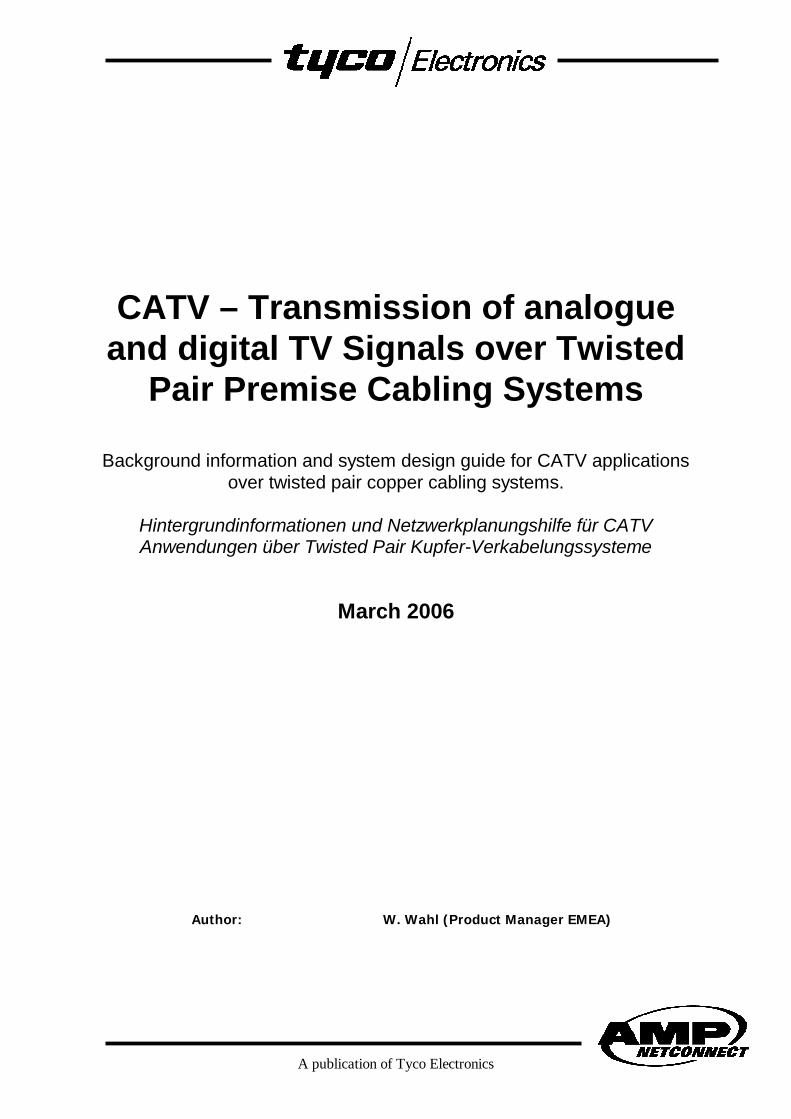
CATV System Overview

3
1. Introduction Einführung
Networks within buildings have become more
and more universal over the past years. Phone
systems and computer networks more and
more use the same infrastructure as defined
by international standard IS 11801 or
european standard EN 50173-1. Most
beneficial for the customer are significantly
lower costs than having plenty dedicated
networks for each apllication separately.
Following this idea next migration step might
be the integration of CATV applications and
replacement of the coaxial network by a few
more twisted pair lines. This document
describes a few basics behind CATV and gives
design support for active equipment required.
Netzwerke innerhalb von Gebäuden sind in den
letzten Jahren sehr viel universeller geworden.
Telefon-Systeme und Computer-Netwerke
nutzen immer häufiger die gleiche Infrastruktur,
wie Sie vom internationalen Standard IS 11801
oder europäischen Standard EN 50173-1
beschrieben sind. Den größten Nutzen hier hat
der Betreiber aufgrund deutlich geringer Kosten
verglichen mit denen einer Vielzahl
anwendungs-spezifischer Netze. Verfolgt man
diese Idee weiter, so ist die Integration von
CATV-Netzen und das Ersetzen der Koax-
Strecken durch wenige zusätzliche Twisted Pair
Leitungen wahrscheinlich der nächste Schritt.
Dieses Dokument gibt wichtige Hintergrund-
Informationen zu CATV und soll bei der
richtigen Dimensionierung der aktiven Geräte
helfen.
2. Bands & frequencies Bänder und Frequenzen
Bands and frequencies for analogue and
digital TV transmission over coaxial networks
and terristric antennas are well defined. An
overview of bands is given in the table below.
Most TV channels in the cable broadcasting
network you find as of economical reasons
below 470 MHz, terrestrical below 606 MHz.
Bänder und Frequenzbereiche wurden für die
digitale und analoge TV-Übertragung über
terrestrische Sender oder Koax-Strecken definiert.
Ein Überblick ist in unten stehender Tabelle
gegeben. Die meisten Kanäle befinden sich im
Kabel aus wirtschaftlichen Gründen unterhalb von
470 MHz und terrestrisch unterhalb von 606 MHz.
Band Description Frequency Application MediaVHF I VHF Band I 47-68 MHz TV cable & aerialVHF II VHF Band II 87,5-108 MHz Radio (FM) cable & aerialUSB Midband 111-125 MHz Radio (DSR) cable & aerialUSB Midband 125-174 MHz TV cable & aerialVHF III VHF Band III 174-230 MHz TV cable & aerialOSB Superband 230-300 MHz TV cable & aerialESB Hyperband 300-470 MHz TV / Radio (DAB) cable & aerialUHF I UHF Band I 470-582 MHz TV / DVB cable & aerialUHF II UHF Band II 582-862 MHz DVB cable
Bands & Frequencies

4
3. Technical Information Technische Informationen
CATV world is based on 75 Ohms while
premise cabling systems are specified for 100
Ohms. To use twisted pair cabling for TV
distribution baluns need to be used.
Sending TV devices typically use output
signals of 75 dBµV, receiving units require
correct signal at 55 dBµV signal strength to
show a clear picture. This means the total
attenuation of the passive link should not
exceed 20 dB. On a purely passive link using
450 MHz bandwith length is restricted to 50
meters for example. Please keep in mind that
the TV provider may not deliver full signal
strength shortening maximum length under 30
meters. Minimum signal strength provided by
the provider should not be lower than 65
dBµV.
To extend the distance in a certain band
amplifiers may be used in the TV links to allow
higher attenuation of longer distances. The
maximum allowed signal strength is 105
dBµV.
Planning and dimensionating the amplifiers it
has to be ensured that maximum input signal
of the TV does not exceed 75 dBµV and is not
less that 52 dBµV. Below of 52 dBµV you may
have to few signal noise ratio. Above 75 dBµV
the receiving unit (TV) may be overpowered.
In both cases you will find a poor picture
quality. Double shielded cables in PiMF
construction are recommended by AMP
Netconnect.
The quality of amplifiers is important as well.
Noisefloor is raised by 3dB even if you use
better ones decreasing signal noise ratio.
Die Fernsehwelt basiert auf 75 Ohm während die
universellen Verkabelungsanlagen für 100 Ohm
spezifiziert sind. Um TV-Signale über Twisted Pair
zu übertragen werden Balune eingesetzt.
Sender der TV Technik arbeiten typischerweise mit
Signalen von 75dBµV, Emfänger brauchen zum
korrekten Empfang ungefährt 55 dBµV um ein
sauberes Bild zu zeigen. Das bedeutet, daß die
Dämpfung im passiven Link 20 dB nicht
überschreiten darf. Will man beispielsweise 450
MHz Bandbreite auf einem passiven Link
übertragen, so ist die Länge auf 50 Meter
begrenzt. Zu beachten ist, daß manchmal die
Kabel-Provider nicht die volle Leistung
bereitstellen, so daß die maximale Länge unter 30
Meter sinken würde. Die Minimalleistung die vom
Provider geliefert wird, sollte 65 dBµV nicht
unterschreiten.
Um die Entfernungen zu verlängern, können
Verstärker in TV-Links eingesetzt werden. Die
maximal erlaubte Signalstärke beträgt 105 dBµV.
Wenn Verstärker dimensioniert und geplant
werden, muß sichgestellt werden daß das
maximale Eingangssignal am TV 75 dBµV nicht
überschreitet und 52 dBµV nicht unterschreitet.
Unterhalb ergibt sich ein schlechter Signal-
Rauschabstand, überhalb übersteuert die
Empfangseinheit (TV). In beiden Fällen wird die
Bildqualität schlecht. Doppelt geschirmte Kabel in
PiMF –Ausführung werden von AMP Netconnect
empfohlen.
Die Qualität der Verstärker ist nicht
unentscheidend. Der Noise-Pegel wird ca. 3dB
angehoben, auch wenn gute Verstärker eingesetzt
werden.
A publication of Tyco Electronics
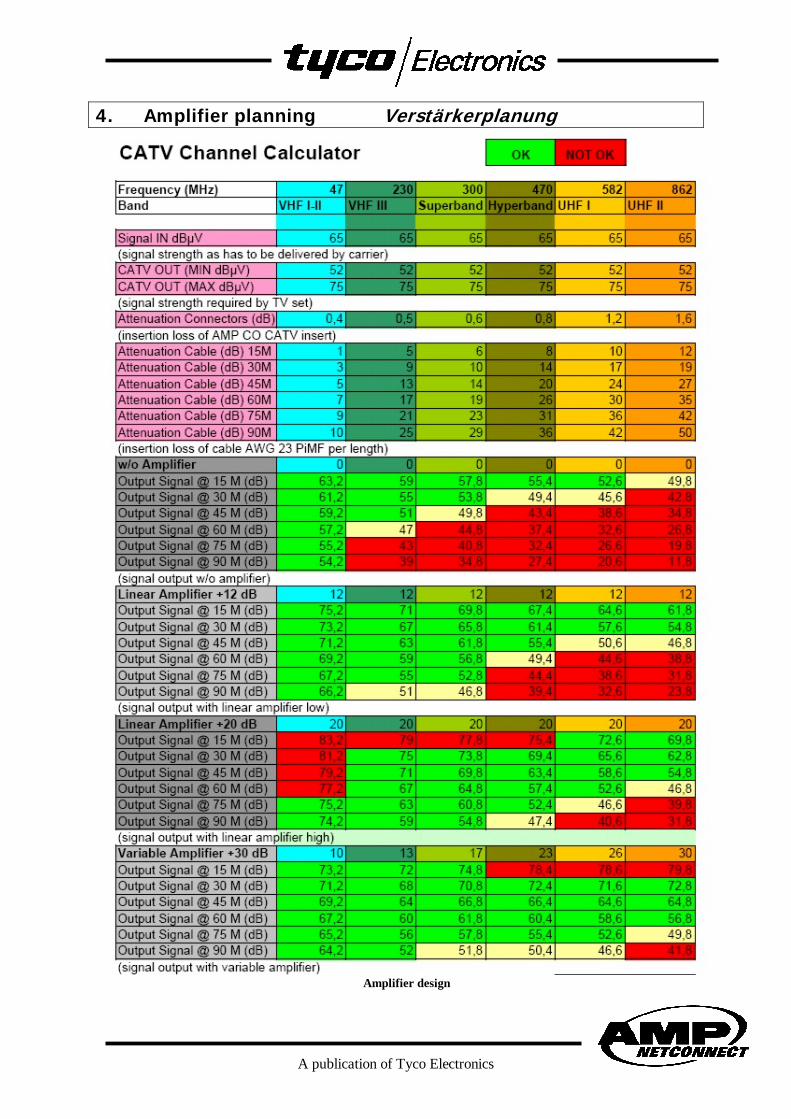
4. Amplifier planning Verstärkerplanung
Amplifier design
6
First of all at the incoming signal strength
should be around 65 dBµV. If a lot weaker
signal is found, all active devices like
amplifiers would gain both signal and noise
which does not give a nice signal noise ratio.
In this case the coax broadcasting network
needs to be checked.
Attenuation of the CATV system distributed
over the premise cabling system using twisted
pair copper cables depend on frequencies
used and the length of the link. The higher the
max. used frequency is and the longer the
link, the more signal attenuation is found.The
CATV channel calculater table on page 5 gives
an overview of the attenuation of connectors
with baluns (one each side) and cable. The
cable used in this calculator is a AWG 23 PiMF
construction. Cable attenuation may vary
using other diameters or constructions. Please
refer to cable data sheet provided with the
cable used.
First estimated length of the CATV link needs
to be defined. The next longer length may be
selected if exact length cannot be found.
Second the frequency band where signals
should be transmitted has to be selected
(columns).
Check the rows indicating required length and
column defining your frequency bands until
only values on green background are found.
Values on red background indicate not
possible as the values are above maximum
(75 dBµV) or below minimum signal strength
(52 dBµV), values on green background
indicate CATV transmission at good quality
possible. This is given for four different
screnarios using other amplifier types that the
best type can be selected.
Zunächst sollte die Signalstärke des
ankommenden Signales etwa 65 dBµV betragen.
Wenn ein schwächeres Signal vorhanden ist,
verstärken Amplifier sowohl das Signal als auch
das Rauschen, so daß kein ausreichender Signal-
Rauschabstand vorhanden ist. In diesem Fall muß
das Koax TV-Netz überprüft werden.
Die Dämpfung eines CATV Systemes über Twisted
Pair Kupfer-Verkabelungssysteme hängt von der
Länge des Linkes und den genutzen Frequenzen
ab. Je höher die benutzte Frequenz und je länger
die Verkabelungsstrecke ist, desto höhere
Dämpfung des Signales wird auftreten. Der CATV
Channel Calculator auf Seite 5 gibt einen Überblick
über die Dämpfung der Steckverbinder inklusive
der Baluns (einer je Seite) und des Kabels. Das
benutze Kabel in diesem Calkulator ist ein AMG 23
PiMF. Die Dämpfung ändert sich, wenn andere
Querschnitte oder Konstruktionen verwendet
werden. Dann sollte das Datenblatt des Kabels
betrachtet werden.
Erst muß die erwartete Länge der CATV-Strecke
definiert werden. Der nächst höhere Eintrag wird
gewählt, wenn die exakte Länge angegeben ist.
Als nächstes müssen die Frequenzbänder, in
denen Signale übertragen werden sollen,
ausgewählt werden (Spalten).
Prüfen Sie die Zeilen mit entsprechender Linklänge
und Spalten, die die Nutzfrequenzen angeben, bis
Werte auf grünem Hintergrund gefunden werden.
Werte auf rotem Hintergrund bedeuten “nicht
möglich”, weil die Signalwerte überhalb des
Maximums (75 dBµV) oder unterhalb des
Minimums (52 dBµV) liegen, Werte auf grünem
Hintergrund zeigen CATV in guter Qualität
möglich. Dies ist für verschiedene Szenarios mit
diversen Verstärker-Typen angegeben, so daß die
technisch beste Lösung ausgewählt werden kann.
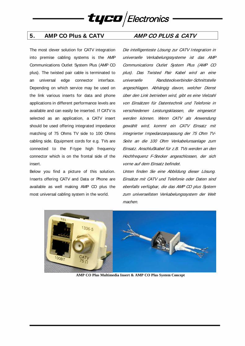
5. AMP CO Plus & CATV AMP CO PLUS & CATV
The most clever solution for CATV integration
into premise cabling systems is the AMP
Communications Outlet System Plus (AMP CO
plus). The twisted pair cable is terminated to
an universal edge connector interface.
Depending on which service may be used on
the link various inserts for data and phone
applications in different performance levels are
available and can easily be inserted. If CATV is
selected as an application, a CATV insert
should be used offering integrated impedance
matching of 75 Ohms TV side to 100 Ohms
cabling side. Equipment cords for e.g. TVs are
connected to the F-type high frequency
connector which is on the frontal side of the
insert.
Below you find a picture of this solution.
Inserts offering CATV and Data or Phone are
available as well making AMP CO plus the
most universal cabling system in the world.
Die intelligenteste Lösung zur CATV Integration in
universelle Verkabelungssysteme ist das AMP
Communications Outlet System Plus (AMP CO
plus). Das Twisted Pair Kabel wird an eine
universelle Randsteckverbinder-Schnittstelle
angeschlagen. Abhängig davon, welcher Dienst
über den Link betrieben wird, gibt es eine Vielzahl
von Einsätzen für Datentechnik und Telefonie in
verschiedenen Leistungsklassen, die eingesetzt
werden können. Wenn CATV als Anwendung
gewählt wird, kommt ein CATV Einsatz mit
integrierter Impedanzanpassung der 75 Ohm TV-
Seite an die 100 Ohm Verkabelunsanlage zum
Einsatz. Anschlußkabel für z.B. TVs werden an den
Hochfrequenz F-Stecker angeschlossen, der sich
vorne auf dem Einsatz befindet.
Unten finden Sie eine Abbildung dieser Lösung.
Einsätze mit CATV und Telefonie oder Daten sind
ebenfalls verfügbar, die das AMP CO plus System
zum universellsten Verkabelungssystem der Welt
machen.
AMP CO Plus Multimedia Insert & AMP CO Plus System Concept
8
6. Satellite TV Satellitenempfang
As the satellites are working on frequencies
around 2.4 GHz, signal transmission of
satellite signals over CATV is hardly possible
and not defined by CATV standards. Using of
TV head stations to convert the GHz signals
down to the bands below 862 MHz are
recommended, if the CATV network should be
connected via satellites.
Satelliten benutzen Frequenzen um 2.4 GHz deren
Übertragung über CATV kaum möglich ist; diese
Frequenzen sind nicht in den für CATV gültigen
Standards definiert. Der Einsatz von TV-
Kopfstationen, die GHz-Signale in Bänder
unterhalb 862 MHz übersetzen, werden
empfohlen, wenn die von CATV-Anbindung über
Satelliten erfolgen soll.
7. Further Informations Weitere Informationen
For further informations about AMP CO plus
and solutions for CATV please contact your
local AMP Netconnect office or visit us at
http://www.ampnetconnect.com/EMEA/
Für weitere Informationen zu AMP CO plus oder
CATV Lösungen kontaktieren Sie bitte Ihr lokales
AMP Netconnect Büro oder besuchen uns unter
http://www.ampnetconnect.de
PDF 032006 © 2006 – Tyco Electronics AMP Deutschland GmbH – All rights reservedTYCO, AMP and NETCONNECT are trademarks. http://www.ampnetconnect.com/EMEA/
AMP Netconnect phone numbers for Europe, Mid East and Africa:
Austria 43-1-90560-1204 Belgium 32-16-352-300 Bulgaria 359-2-971-2151 Croatia 385-1-67-04-46Czech Rep. 420-5-41-162-111 Denmark 45-70-155-200 Egypt 202-417-7647 Estonia 372-6-505-475Finland 358-9-51-234-20 France 33-1-34-20-2122 Germany 49-6103-709-1547 Greece 30-210-9370-396Holland 31-73-6246-211 Hungary 36-1-289-1007 Ireland 353-1-820-3000 Israel 972-3-751-8421Italy 39-011-401-2111 Lithuania 370-5213-1402 Norway 47-66-77-88-99 Poland 48-22-4576-700Portugal 34-93-2910-330 Romania 40-21-311-3479 Slovakia 420-541-162-112 Slovenia 386-15-61-3270South Africa 27-41-405-4500 Spain 34-93-291-0330 Sweden 46-8-5072-5000 Switzerland 41-71-447-0447Turkey 90-212-281-8181 Ukraine 380-44-238-6908 United K. 44-208-420-8140Russia: Moscow 7-095-926-5506 St. Petersburg 7-812-118-8192Mid East and Africa: 33 1 34-20-2122