Embed Size (px)
Citation preview
Chapter 19
Electrical Plans
Introduction• Electrical plans:
– Display all circuits and systems used by the electrical contractor during installation
– May be placed on floor plan or separate
• Electrical installation phases– Temporary– Rough-in electrical– Finish electrical
Electric Terms and Definitions• Common terms:
– Ampere, volt, watt– Box– Breaker– Circuit– Conductor, conduit– Distribution panel– Electrical work
– Ground– Junction box– Lighting outlet– Meter and meter base– Outlet– Switch leg– Temporary electric service
Electrical Circuit Design• Discuss anticipated electrical needs
– Intended use of rooms– Potential furniture placement– Costs and budgets
• Electrical code requirements– State size of some circuits and placement of
certain outlets and switches
Basic Electrical Design Recommendations
• Electrical systems – Should be designed for convenience of use
and to meet minimum code requirements– Refer to the text for common codes and
convenience applications to consider when designing electrical circuits
Home Automation• Automation:
– Controlling and operating mechanical devices other than human power
– Types of systems:• Entertainment centers• Computerized programming of house functions• Security systems• Radio frequency systems• Structured wiring systems
Electrical Design Considerations• Basic considerations:
– Entry and entry foyer– Patios and porches– Living area – Dining room and
kitchen– Bedrooms and
bathrooms– Laundry/utility room
– Office or hobby room– Hallways and stairs– Garage– Outdoor outlets– Crawl spaces– Smoke detectors– Electronics
Smoke Detectors• Provide safe exit opportunity through early
detection of fire and smoke– UL 217 (Underwriters Laboratories)– NFPA 72 (National Fire Protection Association)
• Installed in each sleeping room, and centrally located in a corridor providing access to bedrooms
Carbon Monoxide Alarms• Required in new residential construction
with fuel-fired appliances or attached garage– UL 2034
• Placed outside of each separate sleeping area in immediate vicinity of bedrooms in dwelling units
• Installed in accordance with manufacturer’s instructions
Universal Electrical Installations• Design accommodating all ages and
possible disabilities should be considered– Switch locations– Convenience outlets– Lighting– Communications
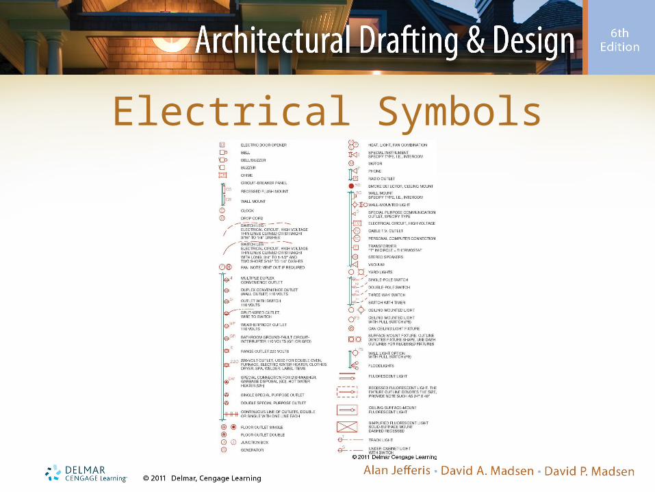
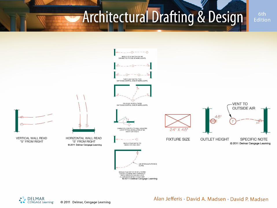
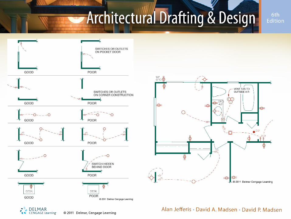
Electrical Symbols
Light Fixture Design and Placement
• Lighting options:– General lighting– Uniform down-lighting– Non-uniform down-lighting– Task lighting– Accent lighting– Light scallop– Recessed lighting
Reflected Ceiling Plans
• Shows features located on ceiling– View if reflected onto a mirror on the floor
• Same orientation as related to floor plan
– Found in set of construction drawings– Often drawn by interior designers– Typically contains ceiling construction and
finish sections, details, and specifications• Also shows special features
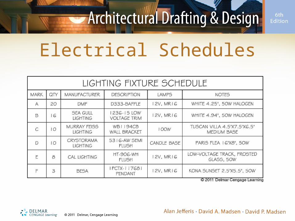
Electrical Schedules
Electrical Wiring Specifications
• Service entrance and meter base installation considerations:– What is the service capacity to be installed?– Where is the service entrance to be located?– Where will the meter base be located?– Where will the distribution panel be located?
Metrics in Electrical Installations
• Electrical conduit designations are expressed in millimeters– Conduit is a metal pipe, fiber pipe, or tube
used to enclose a electrical conductors• Produced in decimal inch dimensions • Identified in nominal inch sizes• Nominal size is referred to as conventional size• Actual size remains in inches but labeled in metric
Steps in Drawing the Electrical Plan
• Draw all light fixtures
• Place all electrical outlets
• Draw all additional electrical symbols
• Letter all switch locations and provide characteristics
Steps in Drawing the Electrical Plan (cont’d.)
• Draw electrical circuits or switch legs from switches to fixtures using a dashed arc line
• Letter all notes, drawing title, and scale
• Add general electrical notes, fixture schedules, and symbol legends
Drawing the Upper Floor Electrical Plan
• Use the same steps to draw upper floor plan electrical layout– Refer to Figure 19-22
• Not all offices display an electrical symbol legend, because standard symbols are typically used
• Good location for electrical fixture schedules or electrical-related schedules
• There are no electrical schedules for the model house
Electrical Plan Drawing Checklist
• Refer to the text for a electrical plan drawing checklist– Check off items while working on an electrical
plan• Ensures everything necessary is included


![Marifix General Contractor [ITA]](https://img.pdfslide.tips/doc/110x75/568c48f51a28ab49169244ec/marifix-general-contractor-ita.jpg)