Embed Size (px)
Citation preview

Chapter 2:
Diode Applications
Islamic University of Gaza
Dr. Talal Skaik

Copyright ©2009 by Pearson Education, Inc.
Upper Saddle River, New Jersey 07458 • All rights reserved.
Electronic Devices and Circuit Theory, 10/e Robert L. Boylestad and Louis Nashelsky
Zener Diodes
2
•A Zener diode is a type of diode that permits current
not only in the forward direction like a normal diode,
but also in the reverse direction if the voltage is larger
than the breakdown voltage known as "Zener voltage“
(VZ).
•Common Zener voltages are between 1.8 V and 200 V.
•Zener diode is used as regulator.
Dr. Talal Skaik 2014

Copyright ©2009 by Pearson Education, Inc.
Upper Saddle River, New Jersey 07458 • All rights reserved.
Electronic Devices and Circuit Theory, 10/e Robert L. Boylestad and Louis Nashelsky
Zener Diodes
3
Approximate equivalent circuits for the Zener diode in the three
possible regions of application.
Dr. Talal Skaik 2014

Copyright ©2009 by Pearson Education, Inc.
Upper Saddle River, New Jersey 07458 • All rights reserved.
Electronic Devices and Circuit Theory, 10/e Robert L. Boylestad and Louis Nashelsky
Example 2.24
4
Determine the reference voltages
provided by the network which uses a white LED
(4V) to indicate power is on. What is the power
delivered to the LED and to the 6 V Zener diode.
Dr. Talal Skaik 2014
Copyright ©2009 by Pearson Education, Inc.
Upper Saddle River, New Jersey 07458 • All rights reserved.
Electronic Devices and Circuit Theory, 10/e Robert L. Boylestad and Louis Nashelsky
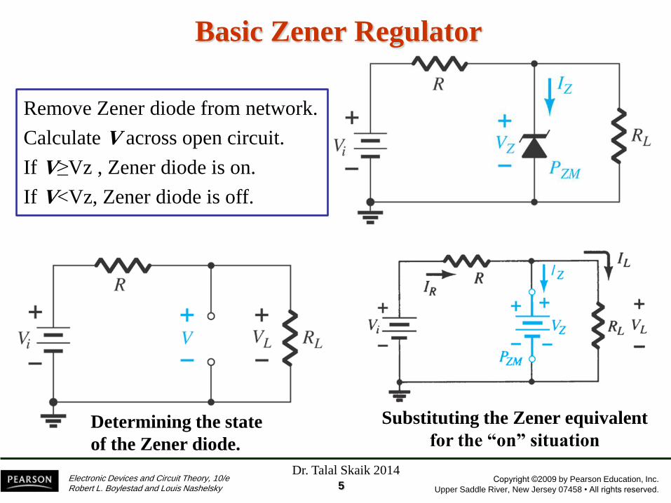
Basic Zener Regulator
5
Determining the state
of the Zener diode.
Substituting the Zener equivalent
for the “on” situation
Remove Zener diode from network.
Calculate V across open circuit.
If V≥Vz , Zener diode is on.
If V<Vz, Zener diode is off.
Dr. Talal Skaik 2014

Copyright ©2009 by Pearson Education, Inc.
Upper Saddle River, New Jersey 07458 • All rights reserved.
Electronic Devices and Circuit Theory, 10/e Robert L. Boylestad and Louis Nashelsky
Example 2.26
6
(a) For the Zener diode network, determine VL, VR, IZ and PZ.
(b) Repeat part (a) with RL=3 kΩ.
Dr. Talal Skaik 2014

Copyright ©2009 by Pearson Education, Inc.
Upper Saddle River, New Jersey 07458 • All rights reserved.
Electronic Devices and Circuit Theory, 10/e Robert L. Boylestad and Louis Nashelsky
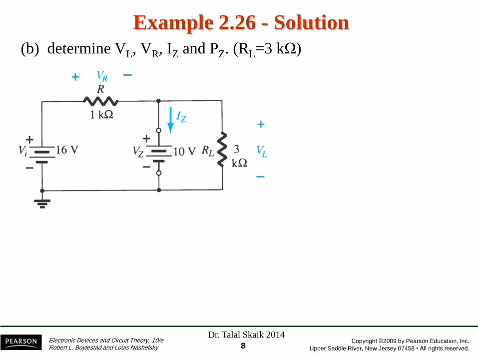
Example 2.26 - Solution
7
(a) determine VL, VR, IZ and PZ. (RL=1.2 kΩ)
V=8.73 V (<10)
IZ=0
Dr. Talal Skaik 2014
Copyright ©2009 by Pearson Education, Inc.
Upper Saddle River, New Jersey 07458 • All rights reserved.
Electronic Devices and Circuit Theory, 10/e Robert L. Boylestad and Louis Nashelsky
Example 2.26 - Solution
8
(b) determine VL, VR, IZ and PZ. (RL=3 kΩ)
Dr. Talal Skaik 2014

Copyright ©2009 by Pearson Education, Inc.
Upper Saddle River, New Jersey 07458 • All rights reserved.
Electronic Devices and Circuit Theory, 10/e Robert L. Boylestad and Louis Nashelsky
Voltage Doubler
9
This half-wave voltage doubler’s output can be calculated by:
Vout = VC2 = 2Vm
where Vm = peak secondary voltage of the transformer
Dr. Talal Skaik 2014

Copyright ©2009 by Pearson Education, Inc.
Upper Saddle River, New Jersey 07458 • All rights reserved.
Electronic Devices and Circuit Theory, 10/e Robert L. Boylestad and Louis Nashelsky
Voltage Doubler
10
• Positive Half-Cycle
o D1 conducts
o D2 is switched off
o Capacitor C1 charges to Vm
• Negative Half-Cycle
o D1 is switched off
o D2 conducts
o Capacitor C2 charges to 2Vm
Vout = VC2 = 2Vm
(a) positive half-cycle; (b) negative half-cycle.
Dr. Talal Skaik 2014

Copyright ©2009 by Pearson Education, Inc.
Upper Saddle River, New Jersey 07458 • All rights reserved.
Electronic Devices and Circuit Theory, 10/e Robert L. Boylestad and Louis Nashelsky
Voltage Doubler
11
Dr. Talal Skaik 2014

Copyright ©2009 by Pearson Education, Inc.
Upper Saddle River, New Jersey 07458 • All rights reserved.
Electronic Devices and Circuit Theory, 10/e Robert L. Boylestad and Louis Nashelsky 12
Practical Applications (AC to DC Converter)
Dr. Talal Skaik 2014

Copyright ©2009 by Pearson Education, Inc.
Upper Saddle River, New Jersey 07458 • All rights reserved.
Electronic Devices and Circuit Theory, 10/e Robert L. Boylestad and Louis Nashelsky
Practical Applications Battery Charger
13
Dr. Talal Skaik 2014

Copyright ©2009 by Pearson Education, Inc.
Upper Saddle River, New Jersey 07458 • All rights reserved.
Electronic Devices and Circuit Theory, 10/e Robert L. Boylestad and Louis Nashelsky
Practical Applications Battery Charger
14
Dr. Talal Skaik 2014

Copyright ©2009 by Pearson Education, Inc.
Upper Saddle River, New Jersey 07458 • All rights reserved.
Electronic Devices and Circuit Theory, 10/e Robert L. Boylestad and Louis Nashelsky
Practical Applications - Polarity insurance
15
(a) Polarity protection for an expensive, sensitive piece of equipment; (b) correctly
applied polarity; (c) application of the wrong polarity.
Dr. Talal Skaik 2014

Copyright ©2009 by Pearson Education, Inc.
Upper Saddle River, New Jersey 07458 • All rights reserved.
Electronic Devices and Circuit Theory, 10/e Robert L. Boylestad and Louis Nashelsky
Practical Applications - Polarity Detector
16
Polarity detector using diodes and LEDs.
Dr. Talal Skaik 2014

Copyright ©2009 by Pearson Education, Inc.
Upper Saddle River, New Jersey 07458 • All rights reserved.
Electronic Devices and Circuit Theory, 10/e Robert L. Boylestad and Louis Nashelsky
Practical Applications – Exit sign using LEDS
17
Dr. Talal Skaik 2014

Copyright ©2009 by Pearson Education, Inc.
Upper Saddle River, New Jersey 07458 • All rights reserved.
Electronic Devices and Circuit Theory, 10/e Robert L. Boylestad and Louis Nashelsky
Practical Applications – AC Regulator
18
Dr. Talal Skaik 2014

Copyright ©2009 by Pearson Education, Inc.
Upper Saddle River, New Jersey 07458 • All rights reserved.
Electronic Devices and Circuit Theory, 10/e Robert L. Boylestad and Louis Nashelsky
Practical Applications – Square-Wave Generator
19
Dr. Talal Skaik 2014