Embed Size (px)
DESCRIPTION
Citation preview

2-1
2Mineral Admixtures
V.M. Malhotra, D.D.L., D.Eng., P.Eng.*
2.1 Fly Ash..................................................................................2-1Introduction • Physical, Chemical, and Mineralogical Properties of Fly Ash • Chemical and Mineralogical Composition • Proportioning Concretes Containing Fly Ash • Influence of Fly Ash on the Setting Time of Portland Cement Concrete • Effect of Fly Ash on Workability, Water Requirement, and Bleeding of Fresh Concrete • Effects of Fly Ash on Air Entrainment in Fresh Concrete • Effects of Fly Ash on Properties of Hardened Concrete • Effects of Fly Ash on the Durability of Concrete
2.2 Blast-Furnace Slag .............................................................2-18Ground, Granulated, or Pelletized Blast-Furnace Slag • Mixture Proportions and Properties of Fresh Concrete Incorporating Blast-Furnace Slag • Properties of Hardened Concrete • Durability of Concrete Incorporating Blast-Furnace Slag • Carbonation
2.3 Silica Fume.........................................................................2-29Production of Silica Fume • Physical and Chemical Characteristics of Silica Fume • Physical and Chemical Mechanisms in the Cement–Silica Fume System • Properties of Fresh Concrete • Properties of Hardened Concrete • Durability Aspects
2.4 Highly Reactive Metakaolin..............................................2-38Chemical and Mineralogical Composition • Properties of Fresh Concrete • Mechanical Properties of Hardened Concrete • Durability Aspects of Hardened Concrete
References .....................................................................................2-42
2.1 Fly Ash
2.1.1 Introduction
Fly ash is a byproduct of the combustion of pulverized coal in thermal power plants. A dust-collectionsystem removes the fly ash, as a fine particulate residue, from combustion gases before they are dischargedinto the atmosphere (Figure 2.1). The types and relative amounts of incombustible matter in the coalused determine the chemical composition of fly ash. More than 85% of most fly ashes is comprised ofchemical compounds and glasses formed from the elements silicon, aluminum, iron, calcium, and
* Scientist Emeritus at CANMET, Natural Resources Canada, Ottawa, Canada; prolific author, editor, and researcherwho has received many awards and honors from the ACI, ASTM, and other institutions throughout the world.

2-2 Concrete Construction Engineering Handbook
magnesium. Generally, fly ash from the combustion of subbituminous coals contains more calcium andless iron than fly ash from bituminous coal; also, fly ash from subbituminous coals contains very littleunburned carbon. Plants that operate only intermittently (peak-load stations) and that burn bituminouscoals produce the largest percentage of unburned carbon. Fly-ash particles are typically spherical, rangingin diameter from <1 µm up to 150 µm.
Fly ashes exhibit pozzolanic activity. The American Society for Testing and Materials (ASTM) (ASTM,1975) defines a pozzolan as “a siliceous or siliceous and aluminous material which in itself possesses littleor no cementitious value but which will, in finely divided form and in the presence of moisture, chemicallyreact with calcium hydroxide at ordinary temperature to form compounds possessing cementitiousproperties.” Fly ashes contain metastable aluminosilicates that will react with calcium ions, in the presenceof moisture, to form calcium silicate hydrates.
The term fly ash was first used in the electrical power industry around 1930. The first comprehensivedata on the use of fly ash in concrete in North America were reported by Davis et al. (1937). The firstmajor practical application was reported in 1948 with the publication of the U.S. Bureau of Reclamation’sdata on the use of fly ash in the construction of the Hungry Horse Dam. Worldwide acceptance of flyash as a component of concrete slowly followed these early efforts, but interest was particularly noticeablein the wake of the rapid increases in energy costs (and hence cement costs) that occurred during the 1970s.
In recent years, it has become evident that fly ashes differ in significant and definable ways that reflecttheir combustion and, to some extent, their origin. The ASTM recognizes two general classes of fly ash:
• Class C, normally produced from lignite or subbituminous coals• Class F, normally produced from bituminous coals
Several publications are available that discuss in detail the properties and use of fly ash in concrete (ASTM,1978; Berry and Malhotra, 1978; Malhotra and Mehta, 1996; Malhotra and Ramezanianpour, 1994), andTable 2.1 shows the estimated production and use of coal ash in major coal-using countries (Malhotraand Ramezanianpour, 1994).
FIGURE 2.1 Schematic of a fossil-fuel plant.
CoalSeam
Overburden
Electrostatic Precipitator
Flue GasFlue Gas
Smoke Stack
Fly Ash
Fly Ash
Bottom Ash
BottomAsh
Boiler
CoalPulverizer
(–150)PlantSurgePile

Mineral Admixtures 2-3
2.1.2 Physical, Chemical, and Mineralogical Properties of Fly Ash
2.1.2.1 Physical Properties
Fly ash is a fine-grained material consisting mostly of spherical, glassy particles. Some ashes also containirregular or angular particles. The size of particles varies depending on the sources. Some ashes may befiner or coarser than Portland cement particles. Figure 2.2 and Figure 2.3 show scanning electron
TABLE 2.1 Coal Ash Production and Use in Major Coal-Using Countries
CountryFly Ash(kt/yr)
Coarse Ash (kt/yr)
Total Ash (kt/yr)
Use(kt/yr)
Use(%) Year
Australia 7050 850 7900 800 10 1990Belgium 930 160 1090 795 73 1989Canada 3830 1420 5250 1575 30 1987France 2200 405 2605 1300 50 1987Germany 7480 4120 11,600 6465 56 1989Italy 1300 135 1435 900 63 1988Japan 3480 445 3925 1920 49 1989Spain 7390 1305 8695 1220 14 1987United Kingdom 9950 2590 12,540 6120 49 1989United States 48,430 16,750 65,190 15,895 24 1989China — — 62,500 16,200 26 1989Czechoslovakia — — 18,100 1400 8 1989East Germany (former GDR) — — 19,100 7200 38 1989Hungary — — 4100 1100 27 1987India — — 40,000 6750 17 1991Poland — — 29,500 4500 15 1989Romania — — 27,000 700 3 1989Former Soviet Union — — 125,000 11,500 9 1989Others — — 116,470 3660 3 1989
Note: In 2007, the total production of fly ash in China, India, and the United States exceeded 80,000, 130,000, and 70,000kilotons a year, respectively.Source: Malhotra, V.M. and Ramezanianpour, A.A., Fly Ash in Concrete, MSL 94-45(IR), Canada Center for Mineral andEnergy Technology (CANMET), Ottawa, 1994.
FIGURE 2.2 SEM micrograph of a subbituminous ash: backscattered electron image of a polished section of thedispersed sample. (From Malhotra, V.M. and Ramezanianpour, A.A., Fly Ash in Concrete, MSL 94-45(IR), CanadaCenter for Mineral and Energy Technology (CANMET), Ottawa, 1994.)

2-4 Concrete Construction Engineering Handbook
microscope (SEM) micrographs of polished sections of subbituminous and lignite fly ashes, and Figure2.4 shows a secondary electron SEM image of bituminous fly-ash particles. Some of these particles appearto be solid, whereas other larger particles appear to be portions of thin, hollow spheres containing manysmaller particles.
FIGURE 2.3 SEM micrograph of a lignite fly ash: backscattered electron image of a polished section of the dispersedsample. (From Malhotra, V.M. and Ramezanianpour, A.A., Fly Ash in Concrete, MSL 94-45(IR), Canada Center forMineral and Energy Technology (CANMET), Ottawa, 1994.)
FIGURE 2.4 SEM micrograph of bituminous fly ash: secondary electron image of the sample. (From Malhotra,V.M. and Ramezanianpour, A.A., Fly Ash in Concrete, MSL 94-45(IR), Canada Center for Mineral and EnergyTechnology (CANMET), Ottawa, 1994.)

Mineral Admixtures 2-5
2.1.2.2 Fineness
Dry- and wet-sieving methods are commonly used to measure the fineness of fly ashes. ASTM C 311-77recommends determining the amount of the sample retained after it is wet sieved on a 45-µm sieve, inaccordance with ASTM C 430, except that a representative sample of the fly ash or natural pozzolan issubstituted for hydraulic cement in the determination. Dry sieving on a 45-µm sieve can be performedaccording to a method established at the Canada Center for Mineral and Energy Technology (CANMET)(Malhotra and Wallace, 1993). Table 2.2 shows the fineness of 11 fly ashes as determined by wet and drysieving. The particle-size distribution of fly ash can be determined by various means, such as x-raysedigraph, laser particle-size analyzer, and Coulter counter. In some cases, agglomeration of a numberof small particles may form a large particle. In most cases, fly ashes contain particles greater than 1 µmin diameter. Mehta (1994), using an x-ray sedimentation technique, reported particle-size distributiondata for several U.S. fly ashes. Mehta found that high-calcium fly ashes were finer than low-calcium flyashes, and he related this difference to the presence of larger amounts of alkali sulfates in the high-calciumfly ashes.
2.1.2.3 Specific Surface
The specific surface of fly ash, which is the area of a unit of mass, can be measured by various techniques.The most common technique is the Blaine specific-surface method, which measures the resistance ofcompacted particles to air flow. ASTM C 204 describes this method for measurement of the surface areaof Portland cement.
2.1.2.4 Specific Gravity
The specific gravity of hydraulic cements is determined according to ASTM C 188. This method can alsobe used to determine the specific gravity of fly ashes. If fly ashes contain water-soluble compounds, theuse of a nonaqueous solvent, instead of water, is recommended. The specific gravity of different fly ashesvaries over a wide range. In the CANMET investigation of 11 fly ashes (Carette and Malhotra, 1986), thespecific gravity ranged from a low value of 1.90 for a subbituminous ash to a high value of 2.96 for aniron-rich bituminous ash. Three subbituminous ashes had a comparatively low specific gravity of ~2.0,and this suggested that hollow particles, such as cenospheres or plerospheres, were present in significantproportions in the three ashes.
TABLE 2.2 Fineness of Fly Ashes
Fly Ash Source
Type of Coala
Physical Properties
Blaine Specific Surface(m2/kg)
Specific Gravity (Le Chatelier
Method)
Fineness (% Retained on 45-µm Sieve)
Wet Sievingb
Dry Sieving (Alpine Jet)
1 B 2.53 17.3 (14.9) 12.3 2892 B 2.58 14.7 (12.7) 10.2 3123 B 2.88 25.2 (21.7) 18.0 1274 B 2.96 19.2 (16.6) 14.0 1985 B 2.38 21.2 (18.3) 16.1 4486 B 2.22 40.7 (35.1) 30.3 3037 SB 1.90 33.2 (28.7) 26.4 2158 SB 2.05 19.4 (16.7) 14.3 3269 SB 2.11 46.0 (39.7) 33.0 240
10 L 2.38 24.9 (21.5) 18.8 28611 L 2.53 2.7 (2.4) 2.5 581
a B, bituminous; L, lignite; SB, subbituminous.b Values in parentheses do not include sieve correction factor.Source: Malhotra, V.M. and Ramezanianpour, A.A., Fly Ash in Concrete, MSL 94-45(IR), Canada Centerfor Mineral and Energy Technology (CANMET), Ottawa, 1994.

2-6 Concrete Construction Engineering Handbook
In general, the physical characteristics of fly ashes vary over a significant range, corresponding to theirsource. Attempts have been made to correlate the physical properties of different fly ashes. In oneCANMET investigation, no apparent relationship was found between type of fly ash and fineness, asdetermined by the percentage retained on a 45-µm sieve. Fineness is probably influenced more by factorssuch as coal combustion and ash collection and classification than by the nature of the coal itself (Caretteand Malhotra, 1986). Similarly, the type of fly ash showed no apparent influence on the specific surfaceas measured by the Blaine technique. Moreover, except in one or two cases, there was very little relation-ship between the specific surface as measured by the Blaine technique and the fineness as determined bypercentage retained on a 45-µm sieve.
2.1.3 Chemical and Mineralogical Composition
2.1.3.1 Chemical Composition
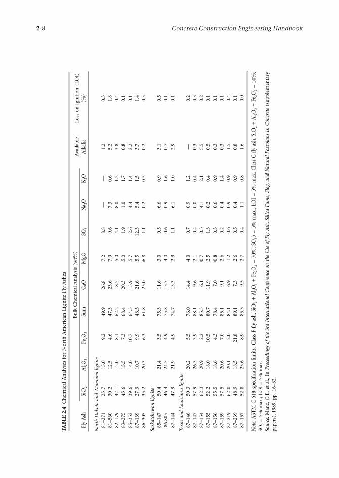
Several authors have reported the chemical composition of various fly ashes produced in North America.In their study of 11 Canadian fly ashes, Carette and Malhotra (1986) reported a wide range of chemicalcompositions (Table 2.3). Manz et al. (1989) examined 19 North American lignite fly ashes, and their dataare given in Table 2.4. The results of the CANMET investigations (Carette and Malhotra, 1986) and thedata reported by Manz et al. (1989) on bituminous, subbituminous, and lignite ashes obtained from variouscoal-powered plants in North America show significant differences in the chemical composition of fly ashes.
2.1.3.2 Mineralogical Composition
In general, both the type and source of fly ash influence its mineralogical composition. Due to the rapidcooling of burned coal in the power plant, fly ashes consist of noncrystalline particles (≤90%), or glassand a small amount of crystalline material. Depending on the system of burning, some unburned coalmay be collected with ash particles. In addition to a substantial amount of glassy material, each fly ashmay contain one or more of the four major crystalline phases: quartz, mullite, magnetite, and hematite.In subbituminous fly ashes, the crystalline phases may include C3A, C4A3S, calcium sulfate, and alkalisulfates (Mehta, 1989). Table 2.5 shows the mineralogical composition of some selected fly ashes. Thereactivity of fly ashes is related to the noncrystalline phase or glass. The reasons for the high reactivityof high-calcium fly ashes may lie partially in the chemical composition of the glass. Mehta (1989) pointedout that the composition of glass in low-calcium fly ashes is different from that in high-calcium fly ashes.
2.1.4 Proportioning Concretes Containing Fly Ash
In most applications, the objective of using fly ash in concrete is to achieve one or more of the followingbenefits:
• Reducing the cement content to reduce costs• Obtaining reduced heat of hydration• Improving workability• Attaining required levels of strength in concrete at ages >90 days• Improving durability
The properties of any particular fly ash will greatly affect the properties of the concrete in which it isused. The mixture-proportioning method can minimize the effects that the inclusion of different flyashes has on concrete performance. In practice, fly ash can be introduced into concrete in one of two ways:
• A blended cement containing fly ash may be used in place of Portland cement.• Fly ash may be introduced as an additional component at the concrete-mixing stage.
The use of blended cement is the simpler of the two, as it is free from the complication of batchingadditional materials and may ensure more uniform control. The relative proportions of fly ash and cementare predetermined, and this limits the range of mixture proportions.

Mineral Admixtures 2-7
TAB
LE 2
.3C
hem
ical
Com
pos
itio
n o
f Fl
y A
shes
Fly-
Ash
So
urc
eTy
pe
of
Coa
la
Ch
emic
al C
ompo
siti
on (
wt%
)bLo
ss o
n I
gnit
ion
(LO
I)
(%)c
SiO
2A
l 2O
3Fe
2O3
CaO
MgO
Na 2
OK
2OT
iO2
P2O
3M
nO
BaO
SO3
1B
47.1
23.0
20.4
1.21
1.17
0.54
3.16
0.85
0.16
0.78
0.07
0.67
2.88
2B
44.1
21.4
26.8
1.95
0.99
0.56
2.32
0.80
0.25
0.12
0.07
0.96
0.70
3B
35.5
12.5
44.7
1.89
0.63
0.10
1.75
0.56
0.59
0.12
0.04
0.75
0.75
4B
38.3
12.8
39.7
4.49
0.43
0.14
1.54
0.59
1.54
0.20
0.04
1.34
0.88
5B
45.1
22.2
15.7
3.77
0.91
0.58
1.52
0.98
0.32
0.32
0.12
1.40
9.72
6B
48.0
21.5
10.6
6.72
0.96
0.56
0.86
0.91
0.26
0.36
0.21
0.52
6.89
7SB
55.7
20.4
4.61
10.7
1.53
4.65
1.00
0.43
0.41
0.50
0.75
0.38
0.44
8SB
55.6
23.1
3.48
12.3
1.21
1.67
0.50
0.64
0.13
0.56
0.47
0.30
0.29
9SB
62.1
21.4
2.99
11.0
1.76
0.30
0.72
0.65
0.10
0.69
0.33
0.16
0.70
10L
46.3
22.1
3.10
13.3
3.11
7.30
0.78
0.78
0.44
0.13
1.18
0.80
0.65
11L
44.5
21.1
3.38
12.9
3.10
6.25
0.80
0.94
0.66
0.17
1.22
7.81
0.82
aB
, bit
um
inou
s; L
, lig
nit
e ; S
B, s
ubb
itu
min
ous.
bB
y in
duct
ivel
y co
upl
ed a
rgon
pla
sma
(IC
AP
) te
chn
iqu
e, e
xcep
t fo
r N
a 2O
, K2O
, SO
3, an
d LO
I.c
105
to 7
50°C
.So
urce
: Mal
hot
ra, V
.M. a
nd
Ram
ezan
ian
pou
r, A
.A.,
Fly
Ash
in
Con
cret
e, M
SL 9
4-45
(IR
), C
anad
a C
ente
r fo
r M
iner
al a
nd
En
ergy
Tec
hn
olog
y (C
AN
ME
T),
Ott
awa,
199
4.
2-8 Concrete Construction Engineering Handbook
TAB
LE 2
.4C
hem
ical
An
alys
es f
or N
orth
Am
eric
an L
ign
ite
Fly
Ash
es
Fly
Ash
Bu
lk C
hem
ical
An
alys
is (
wt%
)A
vaila
ble
Alk
alis
Loss
on
Ign
itio
n (
LOI)
(%
)Si
O2
Al 2
O3
Fe2O
3Su
mC
aOM
gOSO
3N
a 2O
K2O
Nor
th D
akot
a an
d M
onta
na l
igni
te81
–271
25.7
15.0
9.2
49.9
26.8
7.2
8.8
——
1.2
0.3
81–5
6030
.212
.54.
647
.323
.67.
99.
67.
30.
65.
21.
882
–179
42.1
12.0
8.1
62.2
18.5
5.0
4.1
8.0
1.2
3.8
0.4
83–2
7545
.615
.57.
368
.420
.35.
01.
91.
01.
70.
80.
185
–352
39.6
14.0
10.7
64.3
15.9
5.7
2.6
4.4
1.4
2.2
0.1
87–1
3927
.910
.79.
948
.521
.65.
512
.35.
41.
53.
71.
486
–305
35.2
20.3
6.3
61.8
25.0
6.8
1.1
0.2
0.5
0.2
0.3
Sask
atch
ewan
lig
nite
85–1
4750
.421
.43.
575
.311
.63.
00.
56.
60.
93.
10.
586
.805
46.4
24.5
4.9
75.8
13.7
4.0
0.6
0.9
1.6
0.7
0.1
87–1
4447
.921
.94.
974
.713
.32.
91.
16.
11.
02.
90.
1
Texa
s an
d Lo
uisi
ana
ligni
te87
–146
50.3
20.2
5.5
76.0
14.4
4.0
0.7
0.9
1.2
—0.
287
–147
57.9
26.3
3.9
88.1
9.6
2.1
0.4
0.0
0.4
0.3
0.3
87–1
5462
.320
.92.
285
.36.
10.
70.
54.
12.
15.
50.
287
–155
52.2
18.0
10.5
80.7
11.9
2.5
1.3
0.2
0.4
0.5
0.1
87–1
5655
.518
.64.
378
.47.
00.
80.
30.
60.
90.
30.
187
–159
57.5
20.6
7.0
85.1
9.1
2.6
0.2
0.4
1.4
0.3
0.1
87–2
1962
.020
.12.
084
.16.
91.
20.
60.
90.
91.
50.
487
–239
48.9
18.5
21.8
89.1
7.3
2.6
0.5
0.4
0.9
0.8
0.1
87–1
5752
.823
.68.
985
.39.
52.
70.
41.
10.
81.
60.
0
Not
e: A
STM
C 6
18 s
pec
ifica
tion
lim
its:
Cla
ss F
fly
ash
, SiO
2 +
Al 2
O3
+ F
e 2O
2 =
70%
; SO
33 =
5%
max
.; LO
I =
5%
max
. Cla
ss C
fly
ash
, SiO
2 +
Al 2
O3
+ F
e 2O
2 =
50%
;SO
3 =
5%
max
.; LO
I =
5%
max
.So
urce
: M
anz,
O.E
. et
al.,
In P
roce
edin
gs o
f th
e 3r
d In
tern
atio
nal
Con
fere
nce
on t
he U
se o
f Fl
y A
sh, S
ilica
Fum
e, S
lag,
and
Nat
ural
Poz
zola
ns i
n C
oncr
ete
(su
pple
men
tary
pap
ers)
, 198
9, p
p. 1
6–32
.

Mineral Admixtures 2-9
The addition of fly ash at the concrete-mixing stage is flexible and allows for more complete exploitationof the qualities of fly ash as a component of concrete. It does, however, demand that the unique propertiesof fly ash be considered in determining the proportions of the mixture. In current trends, fly ash playsmore than one role in concrete. In freshly mixed concrete, it generally acts as a fine aggregate and tosome degree may reduce the demand for water. In hardened concrete, because of the pozzolanic natureof fly ash, it becomes a component of the cementitious matrix and influences strength and durability.Thus, the use of fly ash in a concrete introduces a number of complexities regarding proportioning, ifthe accepted relationships among workability, strength, and the water/cement ratio are taken into account.Two common assumptions are made when selecting an approach to mixture proportioning of fly-ashconcrete:
• Fly ash usually reduces the strength of concrete at early ages.• For equal workability, concrete incorporating fly ash usually requires less water than concrete
containing only Portland cement.
Neither assumption is universally true, and both are influenced by the presence of other common concretecomponents; however, both assumptions have strongly influenced the approach to mixture proportioningof fly-ash concrete. As with any other type of concrete, the mixture proportions for a fly-ash concretecan be selected either by reference to some standard concrete (excluding fly ash) or on the basis of theways in which all the concrete components (including fly ash) will behave in fresh and hardened states.
Throughout the more than 40 years that fly ash has been used in concrete, common practice has beento use some plain concrete as a standard of comparison for the mixture proportions of fly-ash concretes.Similarly, the properties of both fresh and hardened concrete usually have been compared with those ofa reference concrete. Thus, fly ash has generally been considered to be a replacement for cement, ratherthan a component that complements the functions of the cement, sand, or water. The trend now is toconsider the components of fly-ash concrete as a whole and to treat it as a unique material withoutreference to an equivalent plain-concrete mixture.
2.1.5 Influence of Fly Ash on the Setting Time of Portland Cement Concrete
The rate at which concrete sets during the first few hours after mixing is expressed as the initial and finalsetting time and is determined by some form of penetrometer test. Fly ash may be expected to influencethe rate of hardening of cement for a number of reasons:
• The ash may be cementitious (high calcium).• Fly ash may contain sulfates that react with cement in the same way as the gypsum added to
Portland cement does.
TABLE 2.5 Mineralogical Composition of Some Selected Fly Ashes
Fly-Ash Source
Type of Coala
Phase Composition (%) Loss on Ignition (LOI) (%)Glass Quartz Mullite Magnetite Hematite
1 B 72.1 4.0 12.6 6.2 1.6 3.54 B 70.1 3.2 3.3 17.2 4.7 1.55 B 55.6 6.2 19.8 5.6 3.1 9.76 B 54.2 8.3 23.5 4.4 2.1 7.57 SB 90.2 2.9 6.1 — — 0.88 SB 83.9 4.1 10.2 — 1.4 0.49 SB 79.8 8.7 11.5 — — 0.8
10 L 94.5 4.6 — — — 0.9
a B, bituminous; L, lignite; SB, subbituminous.Source: Carette, G.G. and Malhotra, V.M., Characterization of Canadian Fly Ashes and Their Relative Performance inConcrete, Report 86-6E, Canada Center for Mineral and Energy Technology (CANMET), Ottawa, 1986.

2-10 Concrete Construction Engineering Handbook
• The fly-ash–cement mortar may contain less water as a consequence of the presence of fly ash,and this will influence the rate of stiffening.
• The ash may absorb surface-active agents added to modify the rheology (water reducers) ofconcrete, and, again, this influences the stiffness of the mortar.
• Fly-ash particles may act as nuclei for crystallization of cement hydration products.
There seems to be general agreement in the literature that low-calcium fly ashes retard the setting ofcement. In experiments conducted at CANMET (Carette and Malhotra, 1986), the data show that all but2 of the 11 ashes significantly increase both the initial and final setting times.
2.1.6 Effect of Fly Ash on Workability, Water Requirement, and Bleeding of Fresh Concrete
The small size and the essentially spherical form of low-calcium fly-ash particles influence the rheologicalproperties of cement pastes, causing a reduction in the water required or an increase in workabilitycompared with that of an equivalent paste without fly ash. As Davis et al. (1937) noted, fly ash differsfrom other pozzolans that usually increase the water requirement of concrete mixtures. The improvedworkability allows a reduction in the amount of water used in concrete. According to Owens (1979), themajor factor influencing the effects of ash on the workability of concrete is the proportion of coarsematerial (>45 mm) in the ash. Owens has shown, for example, that substitution of 50% by mass of thecement with fine particulate fly ash can reduce the water requirement by 25%. A similar substitutionusing ash with 50% of the material larger than 45 mm has no effect on the water requirement.
2.1.7 Effects of Fly Ash on Air Entrainment in Fresh Concrete
Cycles of freezing and thawing are extremely destructive to water-saturated concretes that are not properlyproportioned. Concrete will be frost-resistant if it is made with sound, coarse aggregate and is properlyprotected until some maturity is attained. To obtain the number of correctly spaced air voids in hardenedconcrete necessary for frost resistance, an air-entraining admixture (AEA) is added (at a prescribeddosage) to the concrete during mixing. Two attributes are important: (1) the AEA must produce therequired volume of air bubbles of the desired size and spacing in the concrete, and (2) it must do so ina manner that allows the air content to remain stable while the concrete is mixed, transported, and placed.The use of some fly ashes causes an increase in the quantity of AEA required to produce a given level ofair entrainment in fresh concrete. Larson (1994), writing on the use of fly ash in air-entrained concreteand reviewing the work of other investigators, concluded that the primary effect of fly ash was on theAEA requirement rather than on the air entrainment as such.
Gebler and Klieger (1983) examined 10 different fly ashes representing a range of chemical and physicalproperties. Carbon content was 0.14 to 4.19%, total organics were 0.09 to 1.04%, CaO was 1.2 to 9.0%,and fineness (as a percentage retained on a 45-µm sieve) was 11.24 to 38.45%. Concretes were propor-tioned by simple replacement of 25% of the cement by fly ash (by mass). All mixtures were proportionedto have 75 ± 25-mm slump and 6 ± 1% air. Neutralized Vinsol™ resin was the only AEA used. The AEArequirement as a percentage of that for the control concrete (for 6% air content) showed the followingresults:
• For ashes containing >10% CaO, the range of AEA requirements was 126 to 173%.• For ashes containing <10% CaO, the range of AEA requirements was 170 to 553%.
Gebler and Klieger (1983, p. 107) offered the following summary of the findings and conclusions relevantto air entrainment in fresh concrete:
• Generally, concretes containing Class C fly ash require less air-entraining admixture than thoseconcretes with Class F fly ash. All concretes with fly ash required more air-entraining admixturethan Portland cement concretes without fly ash.

Mineral Admixtures 2-11
• Plastic concretes containing Class C fly ash tended to lose less air than concretes with Class F ash.• As the air-entraining admixture requirement increases for a concrete containing fly ash, the air
loss increases.• Air contents in plastic concrete containing Class F fly ash were reduced as much as 59%, 90 minutes
after completion of mixing.• As the organic matter content, carbon content, and loss-on-ignition of fly ash increase, the air-
entraining admixture requirement increases, as does the loss of air in plastic concrete.• Generally, as the total alkalis in fly ash increase, the air-entraining admixture requirement decreases.• As the specific gravity of a fly ash increases, the retention of air in the concrete also increases.
Concrete containing a fly ash that has a high lime content (Class C fly ash) and less organic mattertends to be less vulnerable to loss of air.
• Generally, as the SO3 content of fly ash increases, the retained air in concrete increases.
2.1.8 Effects of Fly Ash on Properties of Hardened Concrete
2.1.8.1 Strength Development in Fly-Ash Concrete
As discussed earlier, the main factors determining strength in concrete are the amount of cement used andthe water/cement ratio. In practice, these are established as a compromise between the need for workabilityin the freshly mixed state, strength and durability in the hardened state, and cost. The degree and mannerin which fly ash affects workability are major factors in its influence on strength development. As was shownearlier, a fly ash that permits a reduction in the total water requirement in concrete will generally presentno problems in selection of mixture proportions and permit any rate of strength development. Manyvariables influence the strength development of fly-ash concrete; the most important are the following:
• The properties of the fly ash• Chemical composition• Particle size• Reactivity• Temperature and other curing conditions
2.1.8.2 Effect of Fly-Ash Type on Concrete Strength
The first difference among fly ashes is that some are cementitious even in the absence of Portland cement;these are the so-called ASTM Class C, or high-calcium, fly ashes, usually produced at power plants thatburn subbituminous or lignitic coals. In general, the rate of strength development in concretes tends tobe only marginally affected by high-calcium fly ashes. Concrete incorporating high-calcium fly ashes canbe made on an equal-weight or equal-volume replacement basis without any significant effect on strengthat early ages. Yuan and Cook (1983) examined the strength development of concretes with and withouthigh-calcium fly ash (CaO = 30.3 wt%). The data from their research are shown in Figure 2.5 and Figure2.6. Using a simple replacement method of mixture proportioning (Table 2.6), they found the rate ofstrength development of fly-ash concrete to be comparable to that of the control concrete, with or withoutair entrainment. Low-calcium fly ashes, the so-called ASTM Class F fly ashes, were the first to be examinedfor use in concrete. Most of what has been written on the behavior of fly-ash concrete examines concretesthat use Class F ashes. In addition, the ashes used in much of the early work came from older powerplants and were coarse in particle size, contained unburned fuel, and were often relatively inactivepozzolans. Used in concrete and proportioned by simple replacement, these ashes showed exceptionallyslow rates of strength development. This led to the erroneous view that fly ash reduces strength at allages. Gebler and Klieger (1986) evaluated the effect of ASTM Class F and Class C fly ashes from 10different sources on the compressive strength development of concretes under different curing conditions,including effects of low temperature and moisture availability. Their tests indicated that concrete con-taining fly ash had the potential to produce satisfactory compressive strength development. The influenceof the class of fly ash on the long-term compressive strength of concrete was not significant. In general,

2-12 Concrete Construction Engineering Handbook
compressive strength development of concretes containing Class F fly ash was more susceptible to lowcuring temperature than concretes with Class C fly ash or the control concretes. Gebler and Kliegerconcluded that Class F fly-ash concretes required more initial moist curing for long-term, air-curedcompressive strength development than did concretes containing Class C fly ashes or the control concretes.
2.1.8.3 Effects of Temperature and Curing Regime on Strength Development in Fly-Ash Concretes
When concrete made with Portland cement is cured at temperatures greater than 30°C, an increase instrength occurs at early ages but a marked decrease in strength in the mature concrete. Concretescontaining fly ash and control concretes behave significantly differently. Figure 2.7 shows the general wayin which the temperature maintained during the early ages of curing influences the 28-day strength ofconcrete (Williams and Owens, 1982).
2.1.8.4 Effect of Fly-Ash on Elastic Properties of Concrete
Published data indicate that fly ash has little influence on the elastic properties of concrete. Abdun-Nur(1961) made the following observation:
The modulus of elasticity of fly ash concrete is lower at early ages and higher at later ages. In general,fly ash increases the modulus of elasticity of concrete when concretes of the same strength with andwithout fly ash are compared.
FIGURE 2.5 Compressive strength development of non-air-entrained concretes containing high-calcium fly ash.(From Yuan, R.L. and Cook, J.E., in Fly Ash, Silica Fume, Slag, and Other Mineral Byproducts in Concrete, Spec. Publ.SP-79, Malhotra, V.M., Ed., American Concrete Institute, Detroit, MI, 1983, pp. 307–319.)
FIGURE 2.6 Compressive strength development of air-entrained concrete containing high-calcium fly ash. (FromYuan, R.L. and Cook, J.E., in Fly Ash, Silica Fume, Slag, and Other Mineral Byproducts in Concrete, Spec. Publ. SP-79,Malhotra, V.M., Ed., American Concrete Institute, Detroit, MI, 1983, pp. 307–319.)
60
55
50
45
40
35
30
Non-air-entrained concreteW/C = 0.45
0% (Control)20% Fly Ash Replacement30% Fly Ash Replacement50% Fly Ash Replacement
Com
pres
sive
Stre
ngth
(MPa
)
5 10 20 30 40 50 60 70 80 90 95Time (Days)
Air-entrained concrete (6.3–6.9%)W/C = 0.45
Com
pres
sive
Stre
ngth
(MPa
)
Time (Days)
45
40
35
30
25
205 10 20 30 40 50 60 70 80 90 95
0% (Control)20% Fly Ash Replacement30% Fly Ash Replacement50% Fly Ash Replacement

Mineral Admixtures 2-13
2.1.8.5 Effect of Fly Ash on Creep Properties of Concrete
Data on creep of fly-ash concrete are limited. Ghosh and Timusk (1981) examined bituminous fly ashesof different carbon contents and fineness values in concretes at nominal strength levels of 20, 35, and 55MPa (water/cement ratio of 1.0, 0.4, and 0.2, respectively). Each concrete was proportioned for equivalentstrength at 28 days. Fly-ash concretes showed less creep in the majority of specimens than the referenceconcretes. This was attributed to a relatively higher rate of strength gain after the time of loading for thefly-ash concretes than for the reference concretes. Yuan and Cook (1983) investigated creep of high-strength concrete containing a high-calcium fly ash and showed that concrete containing 30 and 50%fly ash exhibited more creep than either the control concrete or a concrete with 20% fly ash.
TABLE 2.6 Mixture Designations, Proportions, and Properties of Concrete Incorporating High-Calcium Fly Ash
Mixture Designation
C1 C2 C3 C4
Proportions (kg/m3)Cement 387 309 272 196Fly ash 0 77 117 196Cement + fly ash 387 386 389 392Water 145 145 146 147Coarse aggregate 1146 1144 1153 1160Fine aggregate 701 690 678 654
PropertiesSlump (cm) 3 9 12 21Air content (%) 2.1 1.9 1.9 1.4Unit weight (kg/m3) 2377 2364 2364 2352Fly ash as percentage of cement 0 20 30 50
Source: Yuan, R.L. and Cook, J.E., in Fly Ash, Silica Fume, Slag, and Other Mineral Byproductsin Concrete, Spec. Publ. SP-79, Malhotra, V.M., Ed., American Concrete Institute, Detroit, MI,1983, pp. 307–319.
FIGURE 2.7 Effect of temperature rise during curing on the compressive strength development of concretes.(From Williams, J.T. and Owens, P.L., in Proceedings of International Symposium on the Use of PFA in Concrete,Cabrera, J.G. and Cusens, A.R., Eds., Department of Civil Engineering, University of Leeds, Leeds, U.K., 1982, pp.301–313.
1.2
1.1
1.0
0.9
0.8
0.7
0.6
0.50 10 20 30 40 50 60
Temperature Rise (°C)
Control Concrete
Fly Ash Concrete
28-D
ay S
treng
th Fa
ctor

2-14 Concrete Construction Engineering Handbook
2.1.8.6 Effect of Fly Ash on Volume Changes of Concrete
It has been generally reported that the use of fly ash in normal proportions does not significantly influencethe drying shrinkage of concrete. Typical of the conclusions of most researchers in this area are thosemade by Davis et al. (1937), who commented as follows:
• For masses of ordinary thickness, such as are normally found in highway slabs and in the wallsand frames of buildings, the drying shrinkage at the exposed surfaces of concrete up to the ageof one year for fly-ash cements is about the same as, or somewhat less than, that for correspondingPortland cement. At a short distance from the exposed surface the drying shrinkage up to the ageof one year is substantially less for concretes containing corresponding Portland cements.
• For very thin sections and for cements of normal fineness, the drying shrinkage of concretescontaining finely ground high-early-strength cements may be somewhat reduced by the use of flyash.
2.1.9 Effects of Fly Ash on the Durability of Concrete
Increasingly, concrete is being selected for use as a construction material in aggressive or potentiallyaggressive environments. Concrete structures have always been exposed to the action of seawater. Inmodern times, the demands placed on concrete in marine environments have increased greatly, asconcrete structures are used in arctic, temperate, and tropical waters to contain and support theequipment, people, and products of oil and gas exploration and production. Concrete structures areused to contain nuclear reactors and must be capable of containing gases and vapors at elevatedtemperatures and pressures under emergency conditions. Concrete is increasingly being placed incontact with sulfate and acidic waters. In all of these instances, the use of fly ash as a concrete materialplays a role, and an understanding of its effect on concrete durability is essential to its correct andeconomical application.
2.1.9.1 Effects of Fly Ash on Permeability of Concrete
A number of investigations have studied the influence of fly ash on the relative permeability of concretepipes containing fly ash substituted for cement in amounts of 30 to 50%. In a study by Davis (1954),permeability tests were made on 150 × 150-mm cylinders at the ages of 28 days and 6 months. The resultsof these tests are shown in Table 2.7. It is clear from these data that the permeability of the concrete wasdirectly related to the quantity of hydrated cementitious material at any given time. After 28 days ofcuring, at which time little pozzolanic activity would have occurred, the fly-ash concretes were morepermeable than the control concretes. At 6 months, this was reversed. Considerable imperviousness haddeveloped, presumably as a result of the pozzolanic reaction of fly ash. Short and Page (1982) reportedon the diffusion of chloride ions in solution into Portland blended cement pastes and found the followingvalues of diffusion coefficient (Dc) for different cement types:
TABLE 2.7 Relative Permeability of Concretes with and without Fly Ash
Fly Ash
W/(C + F) by Weight
Relative Permeability (%)
Type Percent (%) by Weight 28 Days 6 Months
None — 0.75 100 26Chicago 30 0.70 220 5
60 0.65 1410 2Cleveland 30 0.70 320 5
60 0.69 1880 7
Note: W/(C + F) = water/cement + fly ash ratio.Source: Davis, R.E., Pozzolanic Materials With Special Reference to Their Use in Concrete Pipe, TechnicalMemo, American Concrete Pipe Association, Irving, TX, 1954.

Mineral Admixtures 2-15
It was concluded from these data that slag and fly-ash cements were more effective in limiting chloridediffusion in pastes than were normal or sulfate-resisting cements.
2.1.9.2 Effects of Fly Ash on Carbonation of Concrete
In moist conditions, calcium hydroxide, and to a lesser degree, calcium silicates and aluminates inhydrated Portland cement react with carbon dioxide from the atmosphere to form calcium carbonate.The process, termed carbonation, occurs in all Portland cement concretes. The rate at which concretecarbonates is determined by its permeability, the degree of saturation, and the mass of calcium hydroxideavailable for reaction. Well-compacted and properly cured concrete, at a low water/cement ratio will besufficiently impermeable to resist the advance of carbonation beyond the first few millimeters. If carbon-ation progresses into a mass of concrete, two deleterious consequences may follow: shrinkage may occur,and carbonation of concrete immediately adjacent to steel reinforcement may reduce the resistance ofsteel to corrosion.
Nagataki et al. (1986) reported the long-term results of experiments carried out since 1969 thatinvestigated the depth of carbonation in concrete with and without fly ash. The authors concluded thatthe initial curing period affects the carbonation of concrete cured indoors; hence, it is necessary for fly-ash concrete to have a longer curing period in water at early ages. The carbonation of concrete curedoutdoors is not affected by the initial curing period in water, provided it is cured in water for a periodof 7 days.
2.1.9.3 Effects of Fly Ash on the Durability of Concrete Subjected to Repeated Cycles of Freezing and Thawing
It is generally accepted, other criteria also being met, that air entrainment renders concrete frost resistant.Fly ashes, in common with other finely divided mineral components in concrete, tend to cause an increasein the quantity of admixture required to obtain specified levels of entrained air in concrete. In someinstances, the stability of the air or the rate of air loss from fresh concrete is also affected. In general, theobserved effects of fly ash on freezing and thawing durability support the view expressed by Larson (1994):
Fly ash has no apparent ill effects on the air voids in hardened concrete. When a proper volume ofair is entrained, characteristics of the void system meet generally accepted criteria.
Klieger and Gebler (1987) also evaluated the durability of concretes containing ASTM Class F andClass C fly ashes. Their test results indicated that air-entrained concretes, with or without fly ash, thatwere moist cured at 23°C generally showed good resistance to freezing and thawing. For specimens curedat a low temperature (4.4°C), air-entrained concretes with Class F fly ash showed slightly less resistanceto freezing and thawing than similar concretes made with Class C fly ash.
Bilodeau et al. (1991), in an investigation carried out at CANMET, determined the scaling resistanceof concrete incorporating fly ashes. Water/cement + fly ash ratios of 0.35, 0.45, and 0.55 were used.Concrete without fly ash and concretes containing 20 and 30% fly ash as replacement by mass for cementwere made. The results of Bilodeau et al. showed that the concrete containing ≥30% fly ash performedsatisfactorily under the scaling test with minor exceptions (Table 2.8).
Carette and Langley (1990) studied the performance of fly ash concrete subjected to 50 freezing andthawing cycles in the presence of deicing salts. They concluded that the incorporation of fly ash in concretemixtures with ≤30% replacement of Portland cement did not show significant difference in salt-scalingresistance in the presence of a 4% calcium chloride solution when examined by visual rating of surface
Type of Cement Dc Value (×10–9 cm2/s)
Normal Portland 44.7Sulfate-resisting 100.0Fly-ash/Portland 14.7Slag/Portland 4.1

2-16 Concrete Construction Engineering Handbook
deterioration. In the measurement of weight loss due to surface deterioration, which they believed wasa meaningful way to assess surface deterioration, concretes containing fly ash showed greater weight lossthan control concrete. Carette and Langley stated that the surface scaling appeared not to be sensitive tothe length of time that specimens were moist cured or air dried subsequent to initial moist curing, atleast within the periods investigated.
2.1.9.4 Abrasion and Erosion of Fly-Ash Concrete
Under many circumstances, concrete is subjected to wear by attrition, scraping, or the sliding action ofvehicles, ice, and other objects. When water flows over concrete surfaces, erosion may occur. In general,regardless of the type of test performed, the abrasion resistance of concrete is usually found to beproportional to its compressive strength. Similarly, at constant slump, resistance to erosion improveswith increased cement content and strength. It may be anticipated that fly-ash concrete that is incom-pletely or inadequately cured may show reduced resistance to abrasion.
Carrasquillo (1987) examined the abrasion resistance of concretes containing no fly ash, 35% ASTMClass C fly ash, or 35% ASTM Class F fly ash. Specimens tested were cast from concretes having similarstrengths, air contents, and cementitious materials contents. The abrasion resistance of concrete contain-ing Class C fly ash was greater than that of concrete containing Class F fly ash or no fly ash. The lattertwo exhibited approximately equal abrasion resistance; measurement was based on the depth of wear.
Naik et al. (1992) carried out an investigation of the compressive strength and abrasion resistance ofconcrete containing ASTM Class C fly ash. They proportioned concrete mixtures to have cement replace-ment in the range of 15 to 70 wt% fly ash. The water/cementitious materials ratio varied from 0.31 to0.37. Their results showed that the abrasion resistance of concrete containing ≤30% fly ash was similarto that of the control concrete; however, the abrasion resistance of concretes containing >40% fly ashwas lower than that of control concrete without fly ash.
2.1.9.5 Effects of Fly Ash on Sulfate Resistance of Concrete
In 1967, Dikeou (1970) reported the results of sulfate-resistance studies on 30 concrete mixtures madewith Portland cement, Portland fly-ash cement, or fly ash. From this work, it was concluded that all ofthe 12 fly ashes tested greatly improved sulfate resistance. Kalousek et al. (1972) studied the requirementsof concretes for long-term service in a sulfate environment. From their study, they drew the followingconclusions:
TABLE 2.8 Mass of Scaling Residue after 50 Freezing and Thawing Cycles—Series I
Time of Moist
Curing (days)
Time of Air Drying
(weeks)
Mass of Scaling Residue (kg/m3)
W/(C + F) = 0.35 (Percentage of Fly Ash)
W/(C + F) = 0.45 (Percentage of Fly Ash)
W/(C + F) = 0.55 (Percentage of Fly Ash)
0 20 30 0 20 30 0 20 30
3 3 0.195 0.504 0.184 0.149 0.160 0.206 0.123 0.282 0.3214 0.122 0.237 0.208 0.178 0.200 0.680 0.126 0.281 0.6385 0.076 0.128 0.143 0.091 0.243 0.634 1.131 0.734 0.3546 0.100 0.074 0.158 0.105 0.306 0.263 0.129 0.255 0.226
7 3 0.154 0.047 0.371 0.135 0.212 0.362 0.160 0.335 0.4264 0.147 0.092 0.265 0.158 0.448 0.209 0.172 0.312 0.8855 0.098 0.108 0.151 0.114 0.180 0.199 0.119 0.238 0.3966 0.192 0.038 0.223 0.169 0.268 0.177 0.118 0.370 0.562
14 3 0.139 0.670 1.094 0.188 0.264 0.409 0.517 0.895 0.7054 0.144 0.158 0.449 0.126 0.198 0.202 0.131 0.636 0.6255 0.174 0.066 0.493 0.135 0.319 0.839 0.162 0.811 0.6136 0.168 0.064 0.189 0.117 0.293 0.463 0.286 0.728 0.814
Note: Each value represents the average of results from two slabs.Source: Bilodeau, A. et al., in Proceedings of Second CANMET/ACI International Conference on Durability of Concrete,Vol. 1, Spec. Publ. SP-126, Malhotra, V.M., Ed., American Concrete Institute, Detroit, MI, 1991, pp. 201–228.

Mineral Admixtures 2-17
• Eighty-four percent of ASTM Types V and II cement concretes without pozzolan showed a lifeexpectancy of <50 years.
• Certain pozzolans very significantly increased the life expectancy of concrete exposed to 2.1%sodium sulfate solution. Fly ashes meeting current specifications were prominent among the groupof pozzolans showing the greatest improvements.
• Concretes for long-term survival in a sulfate environment should be made with high-qualitypozzolans and a sulfate-resisting cement. The pozzolan should not increase significantly but shouldpreferably decrease the amount of water required.
• Cement to be used in making sulfate-resisting concrete with pozzolan of proven performanceshould have a maximum C3A content of 6.5% and maximum C4AF content of 12%. Restrictionof cements to those meeting present-day specifications for Type V cement does not appear justified.
The fly-ash samples examined by Dikeou (1970) and those examined by Kalousek et al. (1972) originatedfrom bituminous coals.
Dunstan (1976) reported the results of experiments on 13 concrete mixtures made with fly ashes fromlignite or subbituminous coal sources. On the basis of this work, he concluded that lignite and subbitu-minous fly-ash concrete generally exhibited reduced resistance to sulfate attack. The Concrete Manualpublished by the U.S. Bureau of Reclamation gives options for cementitious materials for producingsulfate-resistant concretes (Bureau of Reclamation, 1981; Pierce, 1982).
2.1.9.6 Effects of Fly Ash on Alkali–Aggregate Reactions in Concrete
Shortly after Stanton (1940) discovered that alkali–aggregate reactions (AARs) caused expansion anddamage in some concretes, he reported that the effects could be reduced by adding finely ground reactivematerials to the concrete mixture. Subsequently, a variety of natural and artificial pozzolans and mineraladmixtures, including fly ash, were found to be effective in reducing the damage caused by AARs. Theeffectiveness of fly ash (and other mineral admixtures) in reducing expansion due to AARs appears tobe limited to reactions involving siliceous aggregates. A form of AAR known as the alkali–carbonatereaction (Poole, 1981) is relatively unresponsive to the addition of pozzolans (Swenson and Gillott, 1960).The role of fly ashes in reducing expansion by AAR can be summarized as follows:
• Substantial published data show that low-calcium fly ashes with alkali contents of less than about4% are effective in reducing expansion caused by alkali–silica reactions when the fly ashes are usedat a replacement level in the range of 25–30%. High-volume fly ash concrete is very effective inthis regard.
• The use of high-calcium ashes has received less attention; hence, the background information relevantto their use is less well developed. If they are to be used, there is some indication that effectivereplacement levels may be higher than those for low-calcium ashes.
• The mechanism and details of the control of expansion caused by alkali–silica reactions are notfully understood. Much research remains before a satisfactory understanding can be developed.
2.1.9.7 Effects of Fly Ash on the Corrosion of Reinforcing Steel in Concrete
Recently, an issue of concern has been the corrosion of steel reinforcement in fly-ash concrete structuresexposed to chloride ions from deicing salts or seawater. If the concrete cover over steel reinforcement issufficiently thick and impermeable, it will normally provide adequate protection against corrosion. Theprotective effect of the concrete cover is of both a physical and a chemical nature and functions in three ways:
• It provides an alkaline medium in the immediate vicinity of the steel surface.• It offers a physical and chemical barrier to the ingress of moisture, oxygen, carbon dioxide,
chlorides, and other aggressive agents.• It provides an electrically resistive medium around the steel members.
Under alkaline conditions (pH higher than ~11.5), a protective oxide film will form on a steel surface,rendering it immune to further corrosion.
2-18 Concrete Construction Engineering Handbook
When concrete carbonates and the depth of carbonation reach the steel–concrete boundary, passivationmay be reduced and corrosion may occur if sufficient oxygen and moisture reach the metal surface.Chlorides or other ions may also undermine the protective effect of passivation and encourage corrosion.
The Réunion internationale des laboratoires d’essais et de recherches sur les matériaux et les constructions(RILEM) Technical Committee on Corrosion of Steel in Concrete (1974) made the following statement,which gives perspective to this issue:
The efficiency of the (concrete) cover in preventing corrosion is dependent on many factors whichcollectively are referred to as its “quality.” In this context, the “quality” implies impermeability and ahigh reserve of alkalinity which satisfies both the physical needs and chemical requirements of theconcrete cover. If the concrete is permeable to atmospheric gases or lean in cement, corrosion of thereinforcement can be anticipated and good protection should be attempted by the use of denseaggregate and a well-compacted mix with a reasonably low water/cement ratio. …If chloride corrosionis excepted, it is now usually agreed that carbonation of concrete cover is the essential condition forcorrosion of reinforcement.
As discussed in the Effects of Fly Ash on Carbonation of Concrete section above, the issue of carbonationof fly-ash concrete has received some attention in recent years; however, it is our belief that the carbonationof fly-ash concrete is not a matter of concern, provided attention is paid to obtaining adequate imper-meability in the concrete mass.
2.1.9.8 Effects of Fly Ash on Concrete Exposed to Seawater
Exposure of concrete to the marine environment subjects it to an array of severely aggressive factors,including most of those discussed in the preceding sections of this chapter. Concrete in tidal zones is themost severely attacked, subjected as it is to alternating wetting and drying, wave action, abrasion by sandand debris, frequent freezing and thawing cycles, and corrosion of reinforcement—all occurring in achemically aggressive medium. Permanently immersed concrete is less severely affected.
Very little direct observation of fly-ash concrete in seawater has been reported in the literature,although some research in this area has been reported (Malhotra et al., 1980). In 1978, CANMET(Malhotra et al., 1988, 1992) initiated a long-term project on marine-environment performance ofconcretes incorporating supplementary cementing materials. Test specimens were exposed to repeatedcycles of wetting and drying and up to approximately 100 freezing and thawing cycles per year. Evenunder exposure to severe marine conditions, concretes incorporating 25% fly ash from a bituminoussource were in satisfactory condition after 15 years. The only exceptions were the specimens with awater/cement + fly ash ratio of 0.60. It was concluded that fly-ash concrete at a 25% cement replacementlevel (by mass) can be satisfactory under such conditions of exposure, provided the water/cementitiousmaterials ratio is ≤50.
Whereas permeability is considered to be the major factor affecting the durability of concrete inseawater, it is evident that fly ash has the potential to contribute to a number of aspects of concretedurability in the marine environment. It is clear also that this is an area of fly-ash concrete behavior thatis greatly in need of research.
2.2 Blast-Furnace Slag
2.2.1 Ground, Granulated, or Pelletized Blast-Furnace Slag
Blast-furnace slag is a byproduct of iron manufacture. When it is rapidly quenched with water to aglassy state and finely ground, it develops the property of latent hydraulicity. Most of the slags soproduced are, in themselves, cementitious materials to a certain degree, whereas others become so inthe presence of activators such as Portland cement and calcium sulfate. Their performance in concrete,
Mineral Admixtures 2-19
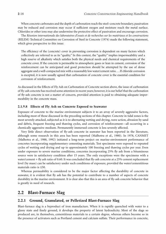
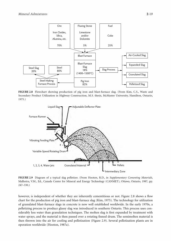
however, is independent of whether they are inherently cementitious or not. Figure 2.8 shows a flowchart for the production of pig iron and blast-furnace slag (Kim, 1975). The technology for utilizationof granulated blast-furnace slags in concrete is now well established worldwide. In the early 1970s, apelletizing process to produce glassy slag was introduced in southern Ontario. This process uses con-siderably less water than granulation techniques. The molten slag is first expanded by treatment withwater sprays, and the material is then passed over a rotating finned drum. The semimolten material isthen thrown into the air for cooling and pelletization (Figure 2.9). Several pelletization plants are inoperation worldwide (Hooton, 1987a).
FIGURE 2.8 Flowchart showing production of pig iron and blast-furnace slag. (From Kim, C.S., Waste andSecondary Product Utilization in Highway Construction, M.S. thesis, McMaster University, Hamilton, Ontario,1975.)
FIGURE 2.9 Diagram of a typical slag pelletizer. (From Hooton, R.D., in Supplementary Cementing Materials,Malhotra, V.M., Ed., Canada Center for Mineral and Energy Technology (CANMET), Ottawa, Ontario, 1987, pp.247–330.)
Ore
Iron Oxides,Silica,
Alumina, etc.
70%
Steel MakingFurnace Process
Steel80%
Steel Slag20%
Fluxing Stone
Limestoneand/or
Dolomite
5%
Slag Process
Fuel
Coke
25%
Blast-FurnaceSlag18%
(1400–1500°C)
Blast Furnace
Pig Iron82%
Air-Cooled Slag
Expanded Slag
Granulated Slag
Pelletized Slag
Adjustable Deflector PlateLiquid Slag
Furnace Runner
Vibrating Feeding Plate
Variable-Speed Rotating Drum
1, 2, 3, 4, Water Jets Granulated Material
Intermediary Zone
Pellets
2 • • 1
• 3
4 •
2-20 Concrete Construction Engineering Handbook
2.2.2 Mixture Proportions and Properties of Fresh Concrete Incorporating Blast-Furnace Slag
2.2.2.1 Mixture Proportions
The proportions of ground, granulated, or ground, pelletized, blast-furnace slag* used in concrete dependon the job requirements. In normal ready-mixed concrete operations, in which the primary aim is toconserve cement, the usual proportions vary from 25 to 50% by weight of cement on a cement-replace-ment basis; however, if the purpose is to enhance some aspect of concrete durability (for example, sulfateresistance), then the slag content is at least 50% of the total cementitious material. As each slag has aunique chemical composition, glass content, and fineness, it is necessary to perform exploratory labo-ratory investigations with the cement, aggregates, and chemical admixtures to be used at a project todetermine the correct percentage of slag to be incorporated into the concrete. This aspect cannot beoveremphasized. The specific gravity of slags ranges from 2.85 to 2.95, compared with 3.15 for Portlandcements; thus, a given replacement of cement by slag on a weight basis results in a higher volume ofpaste in a concrete mixture. This result is of little consequence at lower percentages of cement replacement.If, however, 50 to 75% cement replacements are being considered, this will affect the rheology of theconcrete mixtures and may allow some increase in the volume of coarse aggregate to be used, especiallyin mixtures incorporating higher amounts of cement.
2.2.2.2 Time of Setting
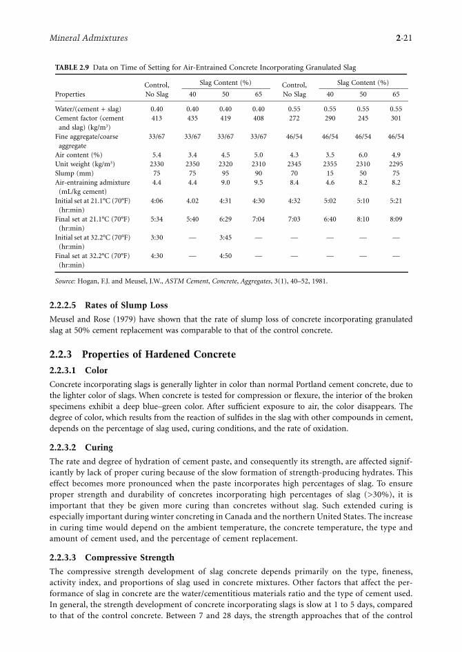
The incorporation of slag as a replacement for Portland cement in concrete normally results in increasedsetting time. Final setting time can be delayed up to several hours depending on the ambient temperature,concrete temperature, and mixture proportions. At temperatures lower than 23°C, considerable retarda-tion in setting time can be expected for slag concretes compared with control concrete, which has seriousimplications in winter concreting. At higher temperatures (>30°C), there is little or no change in thesetting time of slag concrete as compared to control concrete. Data by Hogan and Meusel (1981) oninitial and final setting for concrete incorporating granulated slag are shown in Table 2.9.
2.2.2.3 Bleeding
Few published data are available on the bleeding of slag concretes. Slags are generally ground to a higherfineness than normal Portland cement; therefore, a given mass of slag has a higher surface area than thecorresponding mass of Portland cement. As the bleeding of concrete is governed by the ratio of the surfacearea of solids to the volume of water, in all likelihood the bleeding of slag concrete will be lower thanthat of the corresponding control concrete. The slags available in Canada and the United States havefineness, as measured by the Blaine method, greater than 4500 cm2/g, compared with that of about 3000cm2/g for Portland cement. Thus, in concrete in which a given mass of Portland cement is replaced byan equivalent mass of slag, bleeding should not be a problem.
2.2.2.4 Dosage of Air-Entraining Admixtures
The dosage requirement of an air-entraining admixture to entrain a given volume of air in slag concreteincreases with increasing amounts of slag. The increased demand for the admixture is, once again,probably due to the higher total surface area of the slag particles compared with that of the Portlandcement particles. In an investigation reported by Malhotra (1979), the admixture dosage required toentrain about 5% air increased from 177 mL/m3 for the control concrete to 562 mL/m3 for a concretemixture incorporating 65% pelletized slag. The water/cement + slag ratio was 0.30.
*Granulated slag implies that the slag is granulated by rapid-water quenching of the molten slag, whereas pelletizedslag implies that the granulation is achieved by a pelletizing process. Hereafter, these are referred to either as granulatedor pelletized slag or only as slag when reference is made to both types.
Mineral Admixtures 2-21
2.2.2.5 Rates of Slump Loss
Meusel and Rose (1979) have shown that the rate of slump loss of concrete incorporating granulatedslag at 50% cement replacement was comparable to that of the control concrete.
2.2.3 Properties of Hardened Concrete
2.2.3.1 Color
Concrete incorporating slags is generally lighter in color than normal Portland cement concrete, due tothe lighter color of slags. When concrete is tested for compression or flexure, the interior of the brokenspecimens exhibit a deep blue–green color. After sufficient exposure to air, the color disappears. Thedegree of color, which results from the reaction of sulfides in the slag with other compounds in cement,depends on the percentage of slag used, curing conditions, and the rate of oxidation.
2.2.3.2 Curing
The rate and degree of hydration of cement paste, and consequently its strength, are affected signif-icantly by lack of proper curing because of the slow formation of strength-producing hydrates. Thiseffect becomes more pronounced when the paste incorporates high percentages of slag. To ensureproper strength and durability of concretes incorporating high percentages of slag (>30%), it isimportant that they be given more curing than concretes without slag. Such extended curing isespecially important during winter concreting in Canada and the northern United States. The increasein curing time would depend on the ambient temperature, the concrete temperature, the type andamount of cement used, and the percentage of cement replacement.
2.2.3.3 Compressive Strength
The compressive strength development of slag concrete depends primarily on the type, fineness,activity index, and proportions of slag used in concrete mixtures. Other factors that affect the per-formance of slag in concrete are the water/cementitious materials ratio and the type of cement used.In general, the strength development of concrete incorporating slags is slow at 1 to 5 days, comparedto that of the control concrete. Between 7 and 28 days, the strength approaches that of the control
TABLE 2.9 Data on Time of Setting for Air-Entrained Concrete Incorporating Granulated Slag
PropertiesControl, No Slag
Slag Content (%) Control, No Slag
Slag Content (%)
40 50 65 40 50 65
Water/(cement + slag) 0.40 0.40 0.40 0.40 0.55 0.55 0.55 0.55Cement factor (cement
and slag) (kg/m3)413 435 419 408 272 290 245 301
Fine aggregate/coarse aggregate
33/67 33/67 33/67 33/67 46/54 46/54 46/54 46/54
Air content (%) 5.4 3.4 4.5 5.0 4.3 3.5 6.0 4.9Unit weight (kg/m3) 2330 2350 2320 2310 2345 2355 2310 2295Slump (mm) 75 75 95 90 70 15 50 75Air-entraining admixture
(mL/kg cement)4.4 4.4 9.0 9.5 8.4 4.6 8.2 8.2
Initial set at 21.1°C (70°F) (hr:min)
4:06 4.02 4:31 4:30 4:32 5:02 5:10 5:21
Final set at 21.1°C (70°F) (hr:min)
5:34 5:40 6:29 7:04 7:03 6:40 8:10 8:09
Initial set at 32.2°C (70°F) (hr:min)
3:30 — 3:45 — — — — —
Final set at 32.2°C (70°F) (hr:min)
4:30 — 4:50 — — — — —
Source: Hogan, F.J. and Meusel, J.W., ASTM Cement, Concrete, Aggregates, 3(1), 40–52, 1981.

2-22 Concrete Construction Engineering Handbook
concrete, and beyond this period the strength of slag concrete exceeds the strength of the controlconcrete. Figure 2.10 and Figure 2.11 show compressive strength development with age for granulatedslag concrete for water/cement + slag ratios of 0.40 and 0.55. Note that the highest strength gain at28 days was for concrete with a slag content of 40% cement replacement.
Malhotra et al. (1985) reported investigations in which small amounts of condensed silica fume wereadded to pelletized slag concrete to increase the early-age strength. Figure 2.11 illustrates the strengthdevelopment of concrete from 1 to 180 days. The authors concluded that:
FIGURE 2.10 Age vs. compressive strength relationship for air-entrained concrete: W/(C + S) = 0.40. (From Hogan,F.J. and Meusel, J.W., ASTM Cement, Concrete, Aggregates, 3(1), 40–52, 1981.)
FIGURE 2.11 Age vs. compressive strength relationship for concrete incorporating condensed silica fume andpelletized slag, water/cement + blast-furnace slag (W/(C + BFS)) = 0.50. (From Malhotra, V.M. et al., in Proceedingsof the RILEM/ACI Symposium on the Technology of Concrete When Pozzolans, Slags and Chemical Admixtures Are Used,Monterey, Mexico, 1985, pp. 395–414.)
W/C + S = 0.40 40% Slag
65%50%Control
Slag Type: Granulated (USA)Com
pres
sive
Stre
ngth
(Mpa
)
00 3 7 28
10
20
30
40
Age (Days)
Cement: ASTM Type 1C.A.: Crushed Limestone (19 mm max. size)F.A.: Natural SandA.E.A.: A Sulfonated-Hydrocarbon TypeSuperplasticizer: Naphthalene-Based ProductSpecimen Size: 100×200-mm CylinderCuring Condition: Moist-Curing
Slag Type: Pelletized (Canada)
ReferenceControl
W/C + BFS = 0.50
10%20%15% Silica Fume
5%
Com
pres
sive
Stre
ngth
, MPa
0
10
20
30
40
50
60
70
1 3 7 28 56 91 180Age (Days)
Mineral Admixtures 2-23
• The low early-age strength of Portland cement concrete incorporating blast-furnace slag can beincreased by the incorporation of condensed silica fume. The gain in strength is generally directlyproportional to the percentage of the fume used.
• At 3 days, the increase in strength is generally marginal, especially for concrete with high W/C +blast-furnace slag (BFS) ratios. However, at the age of 14 days and beyond, with minor exceptions,the loss in compressive strength of concrete due to the incorporation of BFS can be fully com-pensated for with a given percentage of condensed silica fume, regardless of the W/(C + BFS).This is also true for the flexural strength.
• The continuing increase in strength at 56, 91, and 180 days of the concrete incorporating BFSand condensed silica fume indicates that sufficient lime (liberated during the hydration ofPortland cement) is present at these ages for the cementitious reaction to continue.
2.2.3.4 Flexural Strength
In general, at 7 days and beyond, the flexural strength of concrete incorporating slag is comparable to,or greater than, the corresponding strength of control concrete; however, in one instance, the reverse wasreported for a water/cement + slag ratio of 0.38. The increased flexural strength of slag concrete is probablydue to the stronger bonds in the cement–slag–aggregate system because of the shape and surface textureof the slag particles.
2.2.3.5 Young’s Modulus of Elasticity
According to Stutterheim (1960), at the same strength level, there is little, if any, difference between themodulus of elasticity of the control concrete and a concrete containing a granulated slag of South Africanorigin. No published data are available on Young’s modulus of elasticity of slags currently available inNorth America. Investigations performed by Nakamura et al. (1986) on a Japanese slag showed nosignificant difference between the values of the Young’s modulus of elasticity of concrete incorporatinggranulated slag and that of the control concrete.
2.2.3.6 Drying Shrinkage
Hogan and Meusel (1981) showed that drying shrinkage of concrete incorporating granulated slag ismore than that of control concrete. The increase in shrinkage is attributed to increased paste volume inconcrete when slag is used as replacement for Portland cement on an equal weight basis because of thelower specific gravity of the slag. This finding may or may not be true for other slags, and further researchis needed to confirm this. Fulton (1974) suggested that the shrinkage of concrete incorporating granulatedslag can be reduced by taking advantage of improved workability to increase the aggregate/cement ratioor by reducing the water/cement ratio of concrete.
2.2.3.7 Creep
Few published data are available on creep of concrete incorporating North American slags. The availabledata from South Africa and Japan are conflicting (Fulton, 1974). This conflict is due primarily to the finenessof slags used, methods of tests, age of testing, humidity conditions, and the stress/strength ratio employed;for example, it has been shown that the fineness of cement significantly affects the creep strains (Fulton,1974). Bamforth (1980) has reported limited data on creep strains for concretes with and without fly ashand granulated slags, loaded to a constant stress/strength ratio of 0.25. He found that for concretes loadedat an age greater than 24 hours, the effects of fly ash and slag significantly reduced the magnitude of thecreep. Neville and Brooks (1975) showed that, when creep tests are performed at ordinary room temperatureand humidity conditions (i.e., 20°C and 60% relative humidity) on test specimens that have been loadedafter moist curing for 28 days, the total creep of the concrete incorporating a slag from a British sourcewas greater than that of the control concrete, although not significantly so. The rationale for this findingmay be that under such test conditions, the rate of gain of strength of the slag concrete is lower than thatof the control concrete.

2-24 Concrete Construction Engineering Handbook
2.2.3.8 Permeability
The permeability of concrete depends mainly on the permeability of the cement paste, which, in turn,depends on its pore-size distribution. Using mercury-intrusion techniques, several investigators (Man-mohan and Mehta, 1981; Mehta, 1983) demonstrated that incorporating granulated slags in cement pastehelps transform large pores into smaller pores, resulting in decreased permeability of the matrix and,hence, of the concrete. The exact mechanism by which the pore refinement occurs in a hydrated slag–cement matrix, however, is not fully understood. Detailed data comparing the permeability of concretewith and without slags are not available, although it has been observed that granulated slag concretesincorporating slags at up to 75% cement replacement have performed satisfactorily when exposed toseawater (Wiebenga, 1980).
2.2.4 Durability of Concrete Incorporating Blast-Furnace Slag
It is believed that the increased durability of Portland cement concrete incorporating blast-furnace slagresults from a finer pore structure and a reduction in easily leached calcium hydroxide in the hardenedcement paste. Subsequently, the volume previously occupied by calcium hydroxide is filled in withhydration products, resulting in a less-permeable material. Permeability controls the physical and chem-ical processes of degradation caused by the action of migrating water; therefore, permeability to waterdetermines the rate of deterioration.
2.2.4.1 Resistance to Sulfate Attack
Sulfates attack concrete and affect its coherence and strength. The resistance of concrete to sulfate attackis improved by partially replacing Portland cement with ground granulated blast-furnace slag. In Ger-many, France, and the Netherlands, cements with a high blast-furnace slag content have been used formany years and are considered appropriate for use in a high-sulfate environment (DIN 1164, 1978; NEN3550, 1979). Hogan and Meusel (1981) carried out a study that demonstrated high resistance to sulfateattack when the granulated slag proportion exceeded 50% of the total cementitious material; ASTM TypeII cements were used. Results of studies carried out by Frearsen (1986) confirmed that ordinary Portlandcements and blends of both ordinary and sulfate-resisting Portland cement containing lower levels ofgranulated slag replacement have inferior resistance to sulfate attack. Sulfate resistance increased withgranulated slag content, and a mortar with 70% slag content was found to have a resistance superior tomortars containing sulfate-resisting Portland cements alone. Also, the influence of slag content on sulfateresistance was found to be more significant than the water/cement ratio in the mixtures investigated.According to Ludwig (1989), the cements exhibiting resistance to sulfate attack are:
• Portland cement with C3A content ≤3 wt%• Portland cement with ≤70% slag content• Nonstandard cements such as high-alumina and supersulfated cements
Bakker (1983) found that slag concretes with a high slag content display an increased resistance to sulfatesbecause of the low permeability of the concrete to different ions and water, as shown by the variouscoefficient values in Table 2.10.
Where granulated slag is used in sufficient quantities, several changes occur that improve resistanceto sulfate attack. These changes include the following:
• The C3A content of the mixture is proportionally reduced depending on the percentage of slagused; however, Lea (1970) reported that increased sulfate resistance depends not only on the C3Acontent of Portland cement alone but also on the Al2O3 content of the granulated slag. Lea furtherreported that sulfate resistance increased where the alumina content of the slag is less than 11%,regardless of the C3A content of the Portland cement when blends with 20 to 50% granulated slagswere used.

Mineral Admixtures 2-25
• Through the reduction of soluble Ca(OH)2 in the formation of calcium silicate hydrates (CSHs),the environment for the formation of ettringite is reduced. Resistance to sulfate attack is greatlydependent on the permeability of the concrete or cement paste. The formation of CSH in porespaces usually occupied by alkalis and Ca(OH)2 reduces the permeability of the paste and preventsthe intrusion of aggressive sulfates.
Mehta (1981) tested pastes incorporating natural pozzolans, rice-husk ash, and granulated slag. The28-day-old paste of the blended cement containing 70% blast-furnace slag showed excellent resistanceto sulfate attack. Few large pores were present in the hydrated paste, although the total porosity (pores>45 Å) was the highest among all the cements tested. The direct relationship between sulfate resistanceof a cement and the slope of its pore-size distribution plot in the range of 500 to 45 Å probably showsthat the presence of a large number of fine pores is associated with improved sulfate resistance of thematerial (Figure 2.12). Although the total porosity of the cement containing 30% slag was considerablyless than the cement containing 70% slag, the former was not found to be sulfate resistant. On the basisof the test results, Mehta proposed that the chemical resistance of blended Portland cements resultsmainly from the process of pore refinement, which is associated with the pozzolanic reactions involvingthe removal of Ca(OH)2.
2.2.4.2 Resistance to Seawater
The action of sulfate in seawater on concrete is rather similar to that of sulfate-bearing groundwater, butin the former case the attack is not accompanied by expansion of the concrete. The absence of expansionis partly due to the presence of a large quantity of chlorides in the seawater that inhibit the expansion;gypsum and calcium sulfoaluminate are more soluble in a chloride solution than in water, so they eitherdo not form or are leached out by the seawater.
Regourd et al. (1977) studied mortar cubes that had been exposed to seawater since 1904 at the portof La Rochelle, France. They concluded that all Portland slag cements with a slag content >60% performwell in seawater. In the case of lower slag content, the MgSO4 reacts with the Ca(OH)2 from C3S and C2Shydration and produces gypsum. The gypsum reacts with the aluminates to form expansive ettringite.Mehta (1989), on the other hand, proposed that the deterioration of concrete by seawater is not char-acterized by expansion but rather is affected by erosion or loss of the solid constituents from the mass.Mehta suggested that ettringite expansion is suppressed in environments where (OH)– ions have beenreplaced by Cl– ions.
TABLE 2.10 Diffusion Coefficients of Na, K, and Cl Ions in Hardened Cement Paste and Mortars Made with Portland and Blast-Furnace Cement after Different Hardening Times
Diffused IonHardening
Time (days)
Dm (10–8 cm2/sec)
Slag Content (%)
Water/Cement Ratio
Portland Cement
Blast-Furnace Cement
Na+ 3 0.50 7.02 1.44 7514 0.50 2.38 0.10 7528 0.55 1.47 0.05 6028 0.60 3.18 0.05 6028 0.65 4.73 0.06 60
K+ 3 0.50 11.38 2.10 7514 0.50 3.58 0.21 75
Cl– 28 0.55 3.57 0.12 6028 0.60 6.21 0.23 6028 0.65 8.53 0.41 60
5 0.50 5.08 0.42 75103 0.50 2.96 0.04 75
60 0.50 4.47 0.41 75
Source: Owens, P.L., Concrete J. Concrete Soc., 13, 21–26, 1979.

2-26 Concrete Construction Engineering Handbook
In seawater, well-cured concretes containing large amounts of granulated slag or pozzolan usuallyoutperform reference concretes containing only Portland cement, partly because the former containless uncombined Ca(OH)2 after curing. In permeable concretes, the normal amount of CO2 presentin seawater is sufficient to decompose the cementitious products. The presence of calcium silicocar-bonate (thaumasite), calcium carboaluminate hydrate (hydrocalumite), and calcium carbonate (ara-gonite) have been reported in cement pastes derived from deteriorated concretes exposed to seawaterfor long periods.
2.2.4.3 Reduction of Expansion Due to Alkali–Silica Reactions
In concrete containing reactive siliceous aggregates, slag cements are preferable to Portland cements,which are rich in alkalis (Regourd, 1980). Research undertaken at the Concrete Research Institute ofthe Dutch Cement Industry and by other investigators (Smolczyk, 1974, 1975) confirmed that the reasonfor the high resistance of concretes incorporating slags to the alkali–silica reaction is the low permeability
FIGURE 2.12 Pore-size distribution of hydrated cements containing 30% or 70% granulated blast-furnace slag.(From Mehta, P.K., in Proceedings of the Fifth International Symposium on Concrete Technology, Rivera, R., Ed.,Monterey, Mexico, 1981, pp. 35–50.)
28 Days
Control
70% Slag
30% Slag
1 Year
Control
70% Slag
30% Slag
Pore Diameter (µm)
1500
1000 80
060
0
400
300
200
150
100 70 45
Pene
tratio
n Vo
lum
e (c
c/g)
0.05
0.10
0.20
0.30
0.15
0.25
(a)
Pore Diameter (µm)
1500
1000 80
060
0
400
300
200
150
100 70 45
Pene
tratio
n Vo
lum
e (c
c/g)
0.05
0.10
0.20
0.30
0.15
0.25
(b)

Mineral Admixtures 2-27
of these concretes to various ions and to water. The low permeability is due not only to the amount ofgel formed but also to the locality where the gel is precipitated; that is, the gel can block a pore whenPortland cement and slag grains are close to each other. The potential alkali–aggregate reactivity forcombinations of Portland cement and granulated slag was investigated by Hogan and Meusel (1981)using ASTM Test C 227; the aggregate used was Pyrex® glass, known to be highly reactive. The dataindicate that the expansion of mortar bars made with slag-cement mixtures and Pyrex® glass is signif-icantly less than for bars made with Portland cement alone. The cement used for these tests had analkali content of 0.51% sodium oxide equivalent, which conforms to the ASTM C 150 specification forPortland cement requirement for low-alkali cement. Suppression of the alkali–aggregate reaction by theaddition of slag was cited by Mather (1965), who suggested that an alkali limit for Portland slag cements,which have a performance equal to that of 0.60% Na2O for Portland cements alone, could be as highas 1.20% Na2O equivalent.
2.2.4.4 Resistance to Repeated Cycles of Freezing and Thawing
Many studies have been published in which granulated blast-furnace slag has been used as partialreplacement for Portland cement in concrete subjected to repeated cycles of freezing and thawing (Fulton,1974; Klieger and Isberner, 1967; Mather, 1957). Results of these studies indicated that, when mortar orconcrete made with granulated slag and Portland cement were tested in comparison with Type I andType II cements, their resistance to freezing and thawing (ASTM C 666, Procedure A) was essentially thesame, provided the concrete was air entrained. Malhotra (1983b) reported results of tests performed inan automatic unit capable of performing eight freezing and thawing cycles per day (ASTM C 666,Procedure B). The percentage of slag used as replacement for normal Portland cement varied from 25to 65 wt% of cement. Initial measurements were taken at 14 days. After about every 100 cycles, thespecimens were measured, weighed, and tested by resonant frequency and by the ultrasonic-pulse velocitymethod. The test was terminated at 700 freezing and thawing cycles. Durability of the exposed concreteprisms was determined from weight, length, resonant frequency, and pulse velocity of the test prismsbefore and after the freezing and thawing cycling, and relative durability factors (ASTM C 666) werecalculated. The test results (Table 2.11) indicated that, regardless of the water/cement + slag ratio andwhether the concretes were air entrained or air entrained and superplasticized, these specimens performedexcellently in freezing and thawing tests, with relative durability factors greater than 91%.
2.2.5 Carbonation
Concrete exposed to air will partially release its free water from the layers next to the surface. Duringevaporation, the pore water in the concrete is replaced by air, and reactions between the CO2 of theatmosphere and the alkali compounds of the concrete take place. This process between the CO2 of theatmosphere and the hydration products of the hardened cement paste is called carbonation. The propertiesof the concrete, as well its protective properties against corrosion of reinforcing steel, are affected by thesereactions. In general, in well-compacted low water/cement ratio slag concrete, carbonation is not aproblem; however, if the concrete incorporates a large percentage of slag, is not cured properly, and hasa high water/cement + slag ratio, then the depth of carbonation will exceed that for normal Portlandcement concrete. Steel in the presence of high concentrations of hydroxyl does not corrode. Bird (1969)suggested that this passivity is the result of the formation of a protective film of gamma ferric oxide onthe surface of the steel. As long as this protective film is maintained by a high pH and is not disruptedby aggressive substances, complete protection of the steel against corrosion is assured. Carbonation canreduce the pH to an extent determined by the permeability of the concrete. Hamada (1968) and Meyer(1968) agreed that carbonation proceeds more rapidly in concretes incorporating slag than in those madewith ordinary Portland cement; however, this finding was disputed by Schröder and Smolczyk (1968),who pointed out that comparative tests should be based on specimens of equal initial permeability ratherthan on specimens of equal age.
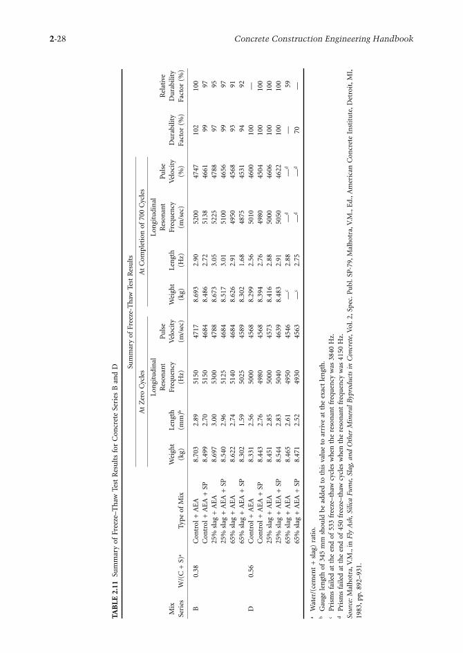
2-28 Concrete Construction Engineering Handbook
TAB
LE
2.1
1Su
mm
ary
of F
reez
e–T
haw
Tes
t R
esu
lts
for
Con
cret
e Se
ries
B a
nd
D
Mix
Se
ries
W/(
C +
S)a
Typ
e of
Mix
Sum
mar
y of
Fre
eze-
Th
aw T
est
Res
ult
s
Du
rabi
lity
Fact
or (
%)
Rel
ativ
e D
ura
bilit
y Fa
ctor
(%
)
At
Zer
o C
ycle
sA
t C
ompl
etio
n o
f 70
0 C
ycle
s
Wei
ght
(kg)
Len
gth
(m
m)b
Lon
gitu
din
al
Res
onan
t Fr
equ
ency
(H
z)
Pu
lse
Vel
ocit
y (m
/sec
)W
eigh
t (k
g)Le
ngt
h
(Hz)
Lon
gitu
din
al
Res
onan
t Fr
equ
ency
(m
/sec
)
Pu
lse
Vel
ocit
y (%
)
B0.
38C
ontr
ol +
AE
A8.
703
2.89
5150
4717
8.69
32.
9052
0047
4710
210
0C
ontr
ol +
AE
A +
SP
8.49
92.
7051
5046
848.
486
2.72
5138
4661
9997
25%
sla
g +
AE
A8.
697
3.00
5300
4788
8.67
33.
0552
2547
8897
9525
% s
lag
+ A
EA
+ S
P8.
540
2.96
5125
4684
8.51
73.
0151
0046
5699
9765
% s
lag
+ A
EA
8.62
22.
7451
4046
848.
626
2.91
4950
4568
9391
65%
sla
g +
AE
A +
SP
8.30
21.
5950
2545
898.
302
1.68
4875
4531
9492
D0.
56C
ontr
ol +
AE
A8.
331
2.56
5000
4568
8.29
92.
5650
1046
0010
0—
Con
trol
+ A
EA
+ S
P8.
443
2.76
4980
4568
8.39
42.
7649
8045
0410
010
025
% s
lag
+ A
EA
8.45
12.
8550
0045
738.
416
2.88
5000
4606
100
100
25%
sla
g +
AE
A +
SP
8.54
42.
8350
4046
398.
483
2.91
5050
4622
100
100
65%
sla
g +
AE
A8.
465
2.61
4950
4546
—c
2.88
—d
—d
—59
65%
sla
g +
AE
A +
SP
8.47
12.
5249
3045
63—
c2.
75—
d—
d70
—
aW
ater
/(ce
men
t +
sla
g) r
atio
.b
Gau
ge l
engt
h o
f 34
5 m
m s
hou
ld b
e ad
ded
to t
his
val
ue
to a
rriv
e at
th
e ex
act
len
gth
.c
Pri
sms
faile
d at
th
e en
d of
533
fre
eze–
thaw
cyc
les
wh
en t
he
reso
nan
t fr
equ
ency
was
384
0 H
z.d
Pri
sms
faile
d at
th
e en
d of
450
fre
eze–
thaw
cyc
les
wh
en t
he
reso
nan
t fr
equ
ency
was
415
0 H
z.So
urce
: M
alh
otra
, V.M
., in
Fly
Ash
, Sili
ca F
ume,
Sla
g, a
nd O
ther
Min
eral
Byp
rodu
cts
in C
oncr
ete,
Vol
. 2, S
pec
. Pu
bl. S
P-79
, Mal
hot
ra, V
.M.,
Ed.
, Am
eric
an C
oncr
ete
Inst
itu
te, D
etro
it, M
I,19
83, p
p. 8
92–9
31.

Mineral Admixtures 2-29
2.3 Silica Fume
2.3.1 Production of Silica Fume
Silica fume is a byproduct of the manufacture of silicon or of various silicon alloys produced in submergedelectric-arc furnaces. The type of alloy produced and the composition of quartz and coal, the two majorcomponents used in the submerged-electric arc furnace, greatly influence the chemical composition ofsilica fume (Malhotra et al., 1987). Most of the published data on the use of silica fume in cement andconcrete are related to silica fume collected during the production of a silicon alloy containing at least75% silicon.
2.3.1.1 Forms of Silica Fume
Silica fume is available commercially in several forms in both North America and Europe:
• As-produced silica fume is silica fume collected in dedusting systems known as bag houses. In thisform, the material is very fine and has a bulk density of about 200 to 300 kg/m3, compared with1500 kg/m3 for Portland cement (Malhotra et al., 1987). As-produced silica fume is available inbags or in bulk. Because of its extreme fineness, this form poses handling problems; in spite ofthis, the material can be and has been transported and handled like Portland cement.
• Compacted silica fume has a bulk density ranging from 500 to 700 kg/m3 and is considerablyeasier to handle than as-produced silica fume. To produce the compacted form, the as-producedsilica fume is placed in a silo, and compressed air is blown in from the bottom of the silo. Thiscauses the particles to tumble, and in doing so they agglomerate. The heavier agglomeratesfall to the bottom of the silo and are removed at intervals. The air compaction of the as-produced silica fume is designed so the agglomerates produced are rather weak and quicklybreak down during concrete mixing. Mechanical means have also been used to produce com-pacted silica fume.
• Water-based silica fume slurry overcomes the handling and transporting problems associated withas-produced silica fume; the slurry contains about 40 to 60% solid particles. Typically, theseslurries have a density of about 1300 kg/m3. Some slurries may contain chemical admixtures suchas superplasticizers, water reducers, and retarders. One such product (known as Force 10,000®)has been successfully marketed in North America.
2.3.2 Physical and Chemical Characteristics of Silica Fume
2.3.2.1 Physical Characteristics of Silica Fume
Silica fume varies in color from pale to dark gray. The carbon content and, to a lesser extent, the ironcontent seem to have significant influence on the color of silica fume. The bulk specific weight is ofthe order of 200 kg/m3 and is 500 kg/m3 when compacted. The specific gravity of silica fume is about2.20. The particles have a wide range of sizes, but they are perfectly spherical (Figure 2.13). The meanparticle diameter is 0.1 µm, compared with 10 µm for particles of cement. The specific surface of silicafume ranges from 13,000 to 30,000 m2/kg as measured by the nitrogen adsorption technique; the valuesfor Portland cement are 300 to 400 m2/kg as measured by the Blaine method. Table 2.12 gives valuesfor the fineness, specific surface, pozzolanic activity index, and specific gravity for silica fume fromthe production of silicon and ferrosilicon alloys (Malhotra et al., 1987). X-ray diffractograms of samplesof different types of silica fume have shown them to be vitreous. All the diffractograms exhibit a verywide scattering peak centered at about 4.4 Å, the most important peak of cristobalite (Figure 2.14).When heated to 1100°C, silica fume crystallizes in the form of cristobalite, except the FeSi-50% type,which crystallizes as enstatite, most probably due to the presence of a high amount of iron andmagnesium oxide.

2-30 Concrete Construction Engineering Handbook
2.3.2.2 Chemical Composition of Silica Fume
The chemical composition of silica fume from different furnaces is given in Table 2.13. A change in thetype of alloy manufactured may cause changes in the characteristics of the silica fume produced; therefore,it is important that concrete plants using silica fume know of any changes in the source of raw materialsused for the furnace or changes in the nature of the alloy being produced by a plant.
2.3.3 Physical and Chemical Mechanisms in the Cement–Silica Fume System
2.3.3.1 Physical Mechanisms
Silica fume enhances the properties of concrete by several physical mechanisms, including increasing thestrength of the bond between the paste and aggregate by reducing the size of the CH crystals in the regionby: (1) providing nucleation sites for the CH crystals so they are smaller and more randomly oriented,and (2) reducing the thickness of the weaker transition zone (Detwiler and Mehta, 1989; Monteiro andMehta, 1986). Physical mechanisms also include increasing the density of the composite system due to
FIGURE 2.13 Typical particle size distribution of silica fume. (From Hjorth, L., in Characterization and PerformancePrediction of Cement and Concrete, Proceedings of the Second Engineering Foundation Conference, Young, J.F., Ed.,Henniker, NH, 1982, p. 165.)
TABLE 2.12 Physical Characteristics of Silica Fume
Physical Characteristics
Nebesar and Carette Results Pistilli et al. Results
Si Silica Fume(24 Samples)
FeSi–75% Silica Fume
(24 Samples)
Mixture of Si and FeSi–75% Silica Fume
(32 Samples)b
FeSi–75% Silica Fume
(30 Samples)
Fineness by 45 µm sieve(% passing)
94.6 98.2 94.0 96.3
Specific surface area (m2/kg) 20,000a 17,200a 3750b 5520b
Pozzolanic activity index with Portland cement (%)
102.8 96.5 91.9 95.3
Water requirement (%) 138.8 139.2 140.1 144.5Pozzolanic activity index with
lime (MPa)8.9 — 7.0 9.1
Specific gravity — — 2.27 2.26
a Nitrogen adsorption.b Blaine permeability.Source: Malhotra, V.M. et al., Condensed Silica Fume in Concrete, CRC Press, Boca Raton, FL, 1987. With permission.
100
80
60
40
20
0
Diameter (µm)0.02 0.05 0.1 0.2 0.5 1.0 2.0 5.0 10
Perc
ent F
iner
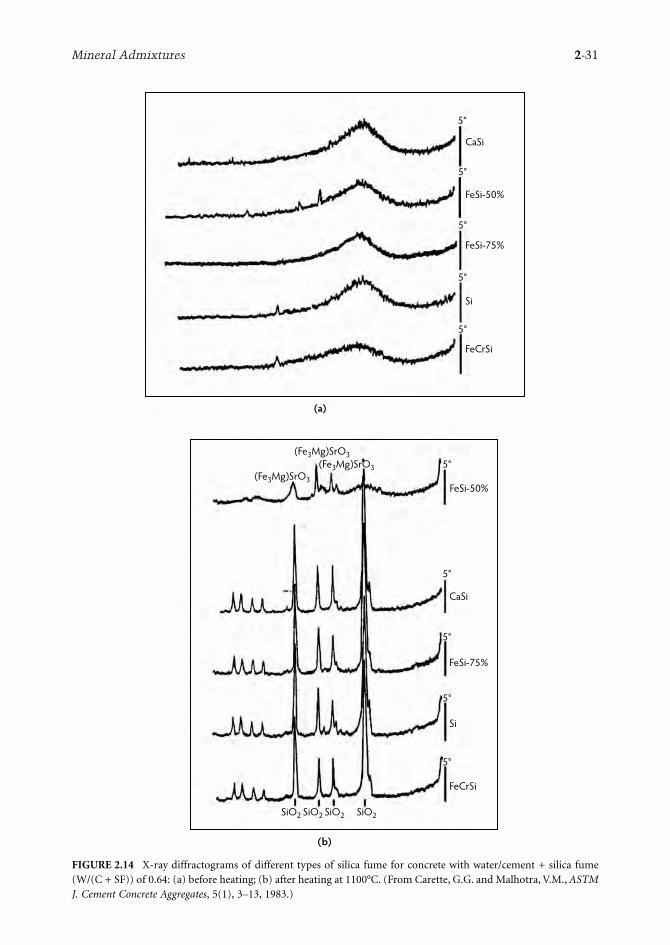
Mineral Admixtures 2-31
FIGURE 2.14 X-ray diffractograms of different types of silica fume for concrete with water/cement + silica fume(W/(C + SF)) of 0.64: (a) before heating; (b) after heating at 1100°C. (From Carette, G.G. and Malhotra, V.M., ASTMJ. Cement Concrete Aggregates, 5(1), 3–13, 1983.)
CaSi
FeSi-50%
FeSi-75%
Si
FeCrSi
CaSi
FeSi-75%
Si
SiO2 SiO2 SiO2 SiO2
FeCrSi
5°
5°
FeSi-50%
5°
5°
5°
5°
5°
5°
5°
5°
(a)
(Fe3Mg)SrO3(Fe3Mg)SrO3
(Fe3Mg)SrO3
(b)

2-32 Concrete Construction Engineering Handbook
the filler packing effect and by providing a more refined pore structure (Bache, 1981; Hjorth, 1982;Sellevold and Nilsen, 1987). For the above mechanisms to take place, it is essential that silica-fumeparticles be well dispersed in a concrete mixture. To achieve this, the use of high-range water reducers(superplasticizers) becomes almost mandatory.
2.3.3.2 Chemical Mechanisms and Pozzolanic Reactions
Malhotra et al. (1987) have reported extensively on the chemical reactions involved in the cement–silicafume–water system. In the presence of Portland cement, the basic reaction, known as the pozzolanicreaction, involves combining finely divided amorphous silica with lime to form a calcium silicate hydrate.
2.3.4 Properties of Fresh Concrete
2.3.4.1 Color
In general, the color of silica-fume concrete is darker than that of conventional concrete. This colordifference is more evident on the surface of wet-hardened concrete and in fresh concrete. Also, inconcretes incorporating high levels of silica fume that has high carbon content, the dark color is morepronounced. In investigations of silica-fume concrete made with dark-colored fume, it was observedthat the color difference disappeared when concrete specimens were stored in the laboratory environ-ment for extended periods. Presumably, this difference in color was neutralized by drying and perhapsby carbonation.
2.3.4.2 Water Demand
Due to its spherical, small particles, silica fume fills the pores between larger grains of cement and givesa better particle-size distribution, leading to a decrease in water demand in silica-fume concrete; however,the high specific area of the silica-fume particles tends to increase water demand, giving a net effect ofincreased water demand compared to Portland cement concrete with the same level of workability. Figure2.15 shows that the increase in water demand is almost directly proportional to the amount of silicafume used in concretes that have an initial water/cement ratio of 0.64 (Carette and Malhotra, 1983).Superplasticizers or high-range water reducers can be used in silica-fume concretes to reduce the waterdemand. In a study using high-resolution nuclear magnetic resonance (NMR) in combination withthermal analysis (DTA/TG), Justnes et al. (1992) investigated the pozzolanicity of condensed silica fume
TABLE 2.13 Chemical Characteristics of Silica Fume
Chemical Composition
Nebesar and Carette Results Pistilli et al. Results
Mixture of Si Silica Fume and FeSi–75% Silica Fume
(32 Samples)
FeSi–75% Silica Fume
(6 Samples)Si Silica Fume(24 Samples)
FeSi–75% Silica Fume
(24 Samples)
SiO2 93.7a 93.2 92.1 91.4Al2O3 0.28 0.3 0.25 0.57Fe2O3 0.58 1.1 0.79 3.86CaO 0.27 0.44 0.38 0.73MgO 0.25 1.08 0.35 0.44Na2O 0.02 0.10 0.17 0.20K2O 0.49 1.37 0.96 1.06S 0.20 0.22 — —SO3 — — 0.36 0.36b
C 3.62 1.92 — —LOI 4.4 3.1 3.20 2.62b
a Calculated.b Thirty samples.Source: Malhotra, V.M. et al., Condensed Silica Fume in Concrete, CRC Press, Boca Raton, FL, 1987. With permission.
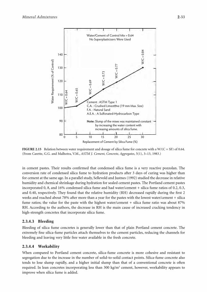
Mineral Admixtures 2-33
in cement pastes. Their results confirmed that condensed silica fume is a very reactive pozzolan. Theconversion rate of condensed silica fume to hydration products after 3 days of curing was higher thanfor cement at the same age. In a parallel study, Sellevold and Justnes (1992) studied the decrease in relativehumidity and chemical shrinkage during hydration for sealed cement pastes. The Portland cement pastesincorporated 0, 8, and 16% condensed silica fume and had water/cement + silica fume ratios of 0.2, 0.3,and 0.40, respectively. They found that the relative humidity (RH) decreased rapidly during the first 2weeks and reached about 78% after more than a year for the pastes with the lowest water/cement + silicafume ratios; the value for the paste with the highest water/cement + silica fume ratio was about 87%RH. According to the authors, the decrease in RH is the main cause of increased cracking tendency inhigh-strength concretes that incorporate silica fume.
2.3.4.3 Bleeding
Bleeding of silica fume concretes is generally lower than that of plain Portland cement concrete. Theextremely fine silica-fume particles attach themselves to the cement particles, reducing the channels forbleeding and leaving very little free water available in the fresh concrete.
2.3.4.4 Workability
When compared to Portland cement concrete, silica-fume concrete is more cohesive and resistant tosegregation due to the increase in the number of solid-to-solid contact points. Silica-fume concrete alsotends to lose slump rapidly, and a higher initial slump than that of a conventional concrete is oftenrequired. In lean concretes incorporating less than 300 kg/m3 cement, however, workability appears toimprove when silica fume is added.
FIGURE 2.15 Relation between water requirement and dosage of silica fume for concrete with a W/(C + SF) of 0.64.(From Carette, G.G. and Malhotra, V.M., ASTM J. Cement, Concrete, Aggregates, 5(1), 3–13, 1983.)
140
130
120
110
100
90
80
Wat
er R
equi
rem
ent (
% o
f Con
trol)
Replacement of Cement by Silica Fume (%)0 5 10 15 20 25 30
W/C
= 0
.64
W/C
= 0
.65
W/C
= 0
.69
W/C
= 0
.73
W/C
= 0
.77 W
/C =
0.8
4
Water/Cement of Control Mix = 0.64No Superplasticizers Were Used
Cement : ASTM Type 1C.A. : Crushed Limestone (19 mm Max. Size)F.A. : Natural SandA.E.A. : A Sulfonated-Hydrocarbon Type
Note: Slump of the mixes was maintained constant by increasing the water content with increasing amounts of silica fume.

2-34 Concrete Construction Engineering Handbook
2.3.4.5 Air Entrainment
Because of the extremely high surface area of the silica fume, the dosage of air-entraining admixturerequired to produce a certain volume of air in silica fume concretes increases considerably with increasingsilica-fume dosage. The presence of carbon in the silica fume adds to the increase in air-entrainingadmixture demand. It has been reported that entrainment of more than 5% air is difficult in concretesthat incorporate high amounts of silica fume, even in the presence of a superplasticizer (Carette andMalhotra, 1983).
2.3.4.6 Shrinkage Cracking
Shrinkage cracking occurs in fresh concrete under curing conditions that cause a net removal of waterfrom exposed concrete surfaces, thus creating tensile stresses beyond the low early-age tensile strengthcapacity of concretes. As concretes containing silica fume show little or no bleeding, thus allowing verylittle water to rise to the surface, the risk of cracking is high in fresh concrete. Shrinkage cracking canbe a very serious problem under curing conditions of elevated temperatures, low humidity, and highwinds, which allow rapid evaporation of water from freshly placed concrete. Johansen (1980) andSellevold (1984) reported that fresh concrete is most vulnerable to shrinkage cracking as it approachesinitial set. To overcome this problem, the surface of concrete should be protected from evaporation bycovering it with plastic sheets or wet burlap or by using curing compounds and evaporation-retardingadmixtures.
2.3.4.7 Setting Time
Ordinary mixtures (with 250 to 300 kg/m3 cement) that incorporate small amounts of silica fume, upto 10% by weight of cement, exhibit no significant difference in setting times compared with conventionalconcretes. As silica fume is invariably used in concretes in combination with water reducers and super-plasticizers, the effect of silica fume on the setting of concrete is masked by the effects of the admixtures.Investigations by Bilodeau (1985) showed that the addition of 5 to 10% silica fume to superplasticizedand nonsuperplasticized concretes had a negligible effect on the setting time of concrete; however, inconcrete with a water/cementitious materials ratio of 0.40 and 15% silica fume, there was a noticeabledelay in setting time. The high dosage of superplasticizer used because of the high silica-fume contentin the concrete could have contributed to the setting delay (Bilodeau, 1985).
2.3.5 Properties of Hardened Concrete
2.3.5.1 Compressive Strength
It is well recognized that silica fume can contribute significantly to the compressive strength developmentof concrete. This is because of the filler effect and the excellent pozzolanic properties of the material,which translate into a stronger transition zone at the paste–aggregate interface. The extent to which silicafume contributes to the development of compressive strength depends on various factors, such as thepercentage of silica fume, the water/cement + silica fume ratio, cementitious materials content, cementcomposition, type and dosage of superplasticizer, temperature, curing conditions, and age.
Superplasticizing admixtures play an important role in ensuring optimum strength development ofsilica-fume concrete. The water demand of silica-fume concrete is directly proportional to the amountof silica fume (used as a percentage replacement for Portland cement) if the slump of concrete is to bekept constant by increasing the water content rather than by using a superplasticizer. In such instances,the increase in the strength of silica-fume concrete over that of control concrete is largely offset by thehigher water demand, especially for high silica-fume content at early ages. In general, the use of super-plasticizer is a prerequisite to achieving proper dispersion of the silica fume in concrete and fully utilizingthe strength potential of the fume. In fact, many important applications of silica fume in concrete dependstrictly upon its utilization in conjunction with superplasticizing admixtures.
Silica-fume concretes have compressive strength development patterns that are generally different fromthose of Portland cement concretes. The strength development characteristics of these concretes are

Mineral Admixtures 2-35
somewhat similar to those of fly-ash concrete, except that the results of the pozzolanic reactions of theformer are evident at earlier ages. This is due to the fact that silica fume is a very fine material with avery high amorphous silica content. The main contribution of silica fume to concrete strength develop-ment at normal temperatures takes place between the ages of about 3 and 28 days. The overall strengthdevelopment patterns can vary according to concrete proportions and composition and are also affectedby the curing conditions.
Carette and Malhotra (1992) reported investigations dealing with the short- and long-term strengthdevelopment of silica-fume concrete under conditions of both continuous water curing and dry curingafter an initial moist-curing period of 7 days. Their investigations covered superplasticized concretesincorporating 0 and 10% silica fume as a replacement by weight for Portland cement and water/cement+ silica fume ratios ranging between 0.25 and 0.40. As expected, the major contributions of silica fumeto the strength took place prior to 28 days; the largest gains in strength of the silica-fume concrete overthe control concrete were recorded at the ages of 28 and 91 days, although this gain progressively diminishedwith age. For concretes with water/cement + silica fume ratios of 0.30 and 0.40, the gain largely disappearedat later ages. Under air-drying conditions, the strength development pattern was found to be significantlydifferent from that of water-cured concretes up to the age of about 91 days; thereafter, however, air dryingclearly had some adverse effect on the strength development of both types of concrete. The effect wasgenerally more severe for silica-fume concrete, where some reduction in strength was recorded betweenthe ages of 91 days and 3.5 years, especially for concretes with water/cement + silica fume ratios of 0.30and 0.40. These trends of strength reduction have not yet been clearly explained, but they appear to stabilizeat later ages and therefore are probably of little practical significance.
Curing temperatures have also been shown to affect significantly the strength development of silica-fume concrete. This aspect has been examined in some detail by several investigators in Scandinavia. Ingeneral, these investigations have indicated that the pozzolanic reaction of silica fume is very sensitive totemperature, and elevated-temperature curing has a greater strength-accelerating effect on silica-fumeconcrete than on comparable Portland cement concrete. The dosage of silica fume is obviously animportant parameter influencing the compressive strength of silica-fume concrete. For general construc-tion, the optimum dosage generally varies between 7 and 10%; however, in specialized situations, up to15% silica fume has been incorporated successfully in concrete.
2.3.5.2 Young’s Modulus of Elasticity
Based on the data published by various investigators, there appears to be no significant differencesbetween the Young’s modulus of elasticity (E) of concrete with and without silica fume. Malhotra etal. (1985) reported data on the Young’s modulus of elasticity of Portland cement–blast-furnace slag–silica-fume concrete. They found no significant difference between the E values obtained at 28 days,regardless of the various percentages of silica fume and water/cementitious materials ratios.
2.3.5.3 Creep
The published data on the creep strain of silica-fume concrete are sparse; Bilodeau et al. (1989) reportedan investigation on the mechanical properties, creep, and drying shrinkage of high-strength concretesincorporating fly ash, slag, and silica fume. The cementitious-material content of the concretes was about530 kg/m3, and the water/cementitious material ratio was 0.22. In addition to the reference concrete,concretes with silica fume at 7 and 12% cement replacements, fly ash at 25% cement replacement, slagat 40% cement replacement, a combination of 7% silica fume and 25% fly ash, and 7% silica fume and40% slag were investigated. Specimens of these concretes were subjected to creep loading after 35 daysof moist curing and an applied stress equivalent to 35% of the compressive strength. After one year, thecreep strains of the reference, 7% silica fume, and 12% silica fume concretes were 1505 × 10–6, 713 ×10–6, and 836 × 10–6, respectively. For concrete with 7% silica fume and 40% slag, the creep strain measuredwas the lowest at 641 × 10–6. The pore structure and minimal quantity of free water in concrete with thehighest amount of supplementary materials could have resulted in these very low creep values, about40% of the creep of the reference concrete.

2-36 Concrete Construction Engineering Handbook
2.3.5.4 Permeability
The incorporation of supplementary cementing materials such as fly ash, slag, silica fume, and naturalpozzolans in concrete results in fine pore structure and changes to the paste–aggregate interface, leadingto a decrease in permeability. This decrease is much higher in concretes incorporating silica fume, dueto its high pozzolanicity. The filler and pozzolanic activity of the silica fume, as well as the virtualelimination of bleeding, improve the interfacial zone through pore refinement. Plante and Bilodeau(1989) reported that the addition of 8% silica fume significantly reduced the penetration of chloride ionsinto concrete. With increasing cementitious materials content and decreasing water/cementitious materialsratios, the chloride-ion penetration was reduced further. At a water/cement + silica fume ratio of 0.21and 500 kg/m3 cement and 40 kg/m3 silica fume, the chloride-ion penetration was found to be 196coulombs at 28 days, compared to 1246 C for the reference concrete. This reduction is primarily due tothe refined pore structure and increased density of the matrix.
2.3.6 Durability Aspects
2.3.6.1 Carbonation
Silica fume, like other pozzolanic materials, reduces the Ca(OH)2 content of the concrete, and thispromotes a faster rate of carbonation. On the other hand, this effect may be offset by the more imper-meable nature of silica-fume concrete, which tends to impede the ingress of CO2 into concrete. The neteffect can be somewhat variable, as it depends on various factors such as silica-fume content, water/cementitious materials ratio, and curing conditions, all of which can have a determinant influence onthe ultimate Ca(OH)2 content and permeability of the concrete. Vennesland and Gjorv (1983) reportedthat using up to 20% silica fume as an addition to cement in concrete, in combination with the use ofa plasticizer, reduced the rate of carbonation. The concrete specimens were initially moist cured for aperiod of 7 days prior to air storage at 60% relative humidity. Carette and Malhotra (1992) comparedthe rate of carbonation of silica-fume concrete with that of reference Portland cement concrete up to theage of 3.5 years. The test specimens had been initially moist cured for 7 days before being stored underambient room drying conditions. At a water/cementitious materials ratio of 0.25, they found that allconcretes remained free of any noticeable carbonation during a 3.5-year period, whereas at a water/cement + silica fume ratio of 0.40, all specimens exhibited signs of carbonation, the effect being slightlymore marked for the silica-fume concrete. In general, however, it is agreed that carbonation is not aproblem in adequately cured, high-quality, low water/cement ratio concrete, and this also applies to silica-fume concrete.
2.3.6.2 Chemical Resistance
Chemical attack on concrete causes destructive expansion and decomposition of the cement paste,leading to severe deterioration. A permeating solvent as innocuous as water can result in the leachingof calcium hydroxide liberated from the hydration of cement. The ingress of chemicals and acids intoconcrete allows them to react with calcium hydroxide to form water-soluble salts that leach out ofconcrete, increasing the permeability of concrete and allowing further ingress of chemicals. Sulfatesreact with calcium hydroxide, forming ettringite, which causes expansion and cracking of the concrete.Silica-fume concretes have better resistance to chemicals than comparable Portland cement concretesdue to the depletion of calcium hydroxide liberated during the hydration of Portland cement by meansof pozzolanic reaction with silica fume, which thus reduces the amount of lime available for leaching,and also due to the decrease in permeability resulting from the refined pore structure of the mortarphase of the concrete.
Mehta (1985) compared the chemical resistance of low water/cement ratio (0.33 to 0.35) concretesexposed to solutions of 1% hydrochloric acid, 1% sulfuric acid, 1% lactic acid, 5% acetic acid, 5%ammonium sulfate, and 5% sodium sulfate. Specimens of a reference concrete, latex-modified concrete,and silica-fume concrete with 15% silica fume by weight of cement were used, and the criteria for failure

Mineral Admixtures 2-37
was 25% weight loss when fully submerged in the above solutions. The investigation showed that concreteincorporating silica fume better resisted chemical attacks than did the other two types of concrete. Theonly exception was the silica-fume concrete specimens immersed in ammonium sulfate solution whichperformed poorly. This was attributed to the ability of the ammonium salts to decompose the calciumsilicate hydrate in the hydrated cement paste.
2.3.6.3 Freezing and Thawing Resistance
Extensive laboratory and field experience in Canada and the United States has shown that, for satisfactoryperformance of concrete under repeated cycles of freezing and thawing, the cement paste should beprotected by incorporating air bubbles, 10 to 100 µm in size, using an air-entraining admixture. Briefly,the most important parameters concerning the entrainment of air in concrete are the air content, bubble-spacing factor, and specific surface. For satisfactory freezing and thawing resistance, it is recommendedthat air-entrained concrete should have bubble-spacing factor (L) values of less than 200 µm and specificsurface (α) greater than 24 mm–1. Usually, fresh Portland cement concrete incorporating between 4 to7% entrained air by volume will yield the above values of L and α.
Several investigators have performed studies on the freezing and thawing resistance of silica-fumeconcrete. These include, among others, Sorensen (1983), Gjorv (1983), Carette and Malhotra (1983),Malhotra (1984), Yamato et al. (1986), Hooton (1987b), Hammer and Sellevold (1990), Virtanen (1985),Pigeon et al. (1986), and Batrakov et al. (1992). In one CANMET investigation, the freezing and thawingresistance of non-air-entrained and air-entrained concrete incorporating various percentages of silicafume was compared (Malhotra, 1984). The study led to the following conclusions:
• Non-air-entrained concrete: Non-air-entrained concrete, regardless of the water/cement + silicafume ratio and irrespective of the amount of condensed silica fume, shows very low durabilityfactors and excessive expansion when tested in accordance with ASTM C 666 (Procedure A or B).The concrete appears to show somewhat increasing distress with increasing amounts of fume;therefore, the use of non-air-entrained condensed silica-fume concrete is not recommended whenit is to be subjected to repeated cycles of freezing and thawing.
• Air-entrained concrete: Air-entrained concrete, regardless of the water/cement + silica fume ratioand containing up to 15% condensed silica fume as partial replacement for cement, performssatisfactorily when tested in accordance with ASTM C 666 (Procedures A and B). However,concrete incorporating 30% of the fume and a water/cement + silica fume ratio of 0.42 performsvery poorly (durability factors less than 10), regardless of the procedure used. This is probablydue to the fact that the hardened concrete has high values of L, or it might be due to the highamount of condensed silica fume in concrete, resulting in a very dense cement matrix system that,in turn, might adversely affect the movement of water. It is difficult to entrain more than 5% airin the above type of concrete, and this amount of air may or may not provide satisfactory L valuesin hardened concrete for durability purposes. The users are therefore asked to exercise cautionwhen using high percentages of condensed silica fume as replacement for Portland cement inconcretes with water/cement + silica fume ratios of the order of 0.40 if these concretes are to besubjected to repeated cycles of freezing and thawing.
2.3.6.4 Frost Resistance in the Presence of Deicing Salts
Limited published data are available on the deicing salt scaling resistance of silica-fume concrete. Gagneet al. (1990) reported that the frost resistance of concrete incorporating 6% silica fume as an additionto cement is satisfactory in the procedure of deicing salt scaling tests (ASTM C 672). This was true forboth air-entrained and non-air-entrained concrete. The water/cement + silica fume ratio of the concretesranged from 0.23 to 0.30, and the concretes were air dried for 28 days before being subjected to thedeicing salt scaling test. Using the ASTM C 672 tests, Bilodeau and Carette (1989) investigated thedeicing salt scaling resistance of Portland cement concrete and concretes incorporating 8% silica fume
2-38 Concrete Construction Engineering Handbook
as replacement for cement. In their investigation, superplasticized and nonsuperplasticized concreteswere made, with water/cementitious materials ratios ranging from 0.40 to 0.65, all having adequate air-void parameters. They reported that, in general, all concretes performed satisfactorily under the actionof deicing salts, although the silica-fume concrete exhibited a slightly inferior performance whencompared to that of Portland cement concrete. In particular, silica-fume concrete with a water/cement+ silica fume ratio of 0.60 showed appreciable weight loss after 50 cycles.
2.3.6.5 Role of Silica Fume in Reducing Expansion Due to Alkali–Silica Reaction
A number of laboratory investigations have indicated that silica fume, like other pozzolans, is effectivein reducing the above-mentioned expansions due to alkali-silica reactions; however, the percentage ofsilica fume to be incorporated into concrete would depend on the type of reactive aggregate, theexposure conditions, the alkali and silica contents, the silica fume used, the type of cement used, andthe water/cementitious materials ratio of the mixture. Published data indicate that the percentagereplacement of cement by silica fume may range from about 10 to 15% (Durand, 1991). CANMET-funded studies have indicated that silica fume is not effective in controlling expansions due to alkali-carbonate reactions (Chen and Sunderman, 1990). At present, no significant well-documented dataare available as to the long-term effectiveness of silica fume in controlling alkali–silica expansions inactual field structures. Based on current knowledge, it is recommended that those contemplating theuse of silica fume to control expansion due to alkali–silica reactions perform accelerated tests in thelaboratory, using the materials to be employed on a job site, to determine the percentage of silica fumeto be used as replacement for cement.
2.4 Highly Reactive Metakaolin
Highly reactive metakaolin has recently become available as a very active pozzolanic material for use inconcrete. Unlike fly ash, slag, or silica fume, this material is not a byproduct but is manufactured froma high-purity kaolin clay by calcination at temperatures in the region of 700 to 800°C (Caldarone et al.,1994). The material, ground to an average particle size of 1 to 2 µm, is white in color. In 1994, a plantwas commissioned in Atlanta to produce the material on a commercial scale.
2.4.1 Chemical and Mineralogical Composition
Unlike silica fume, which contains more than 85% SiO2, highly reactive metakaolin contains equalproportions of SiO2 and Al2O3 by mass. A typical oxide analysis is given below:
The highly reactive metakaolin derives its reactivity from the combination of two factors—namely, atotally noncrystalline structure and a high surface area. As far as mineralogical character is concerned,like silica fume, metakaolin is composed essentially of noncrystalline aluminosilicate (Si-Al-O) phase.Occasionally, a small amount of crystalline impurities may be present—that is, 1 to 2% of quartz, feldspar,or titania. The material has a specific surface of about 20 m2/g and a specific gravity of 2.5.
2.4.2 Properties of Fresh Concrete
According to the limited published data, the initial and final setting time of concrete incorporating10% of metakoalin by mass are comparable to those of control concrete and concrete incorporating
SiO2 Al2O3 Fe2O3 CaO MgO Alkalis Loss on Ignition
51 40 1 2 0.1 0.5 2

Mineral Admixtures 2-39
10% silica fume. Also, the air-entraining admixture demand is similar to that of silica-fume concrete.Because of its very high specific surface, the bleeding of concrete incorporating metakoalin is negligible.According to the data published by Zhang and Malhotra (1995), the autogenous temperature rise ofconcrete made with metakaolin was higher than that of the control and silica-fume concrete at agesup to 6 days, indicating high reactivity of the material (Figure 2.16).
2.4.3 Mechanical Properties of Hardened Concrete
2.4.3.1 Strength Development
Table 2.14 gives some data on strength development and Young’s modulus for concrete made withmetakaolin; also, data on the control concrete and silica fume are included for comparison purposes.The faster strength development of the metakaolin concrete at early ages as compared with the silica-fume concrete is probably due to the faster rate of hydration, as discussed earlier.
2.4.3.2 Drying Shrinkage
Zhang and Malhotra (1995) investigated the drying shrinkage of concrete incorporating metakaolin; thedata are shown in Figure 2.17, together with data for control and silica-fume concrete. The concreteswere exposed to drying shrinkage after 7 days of initial curing in lime-saturated water. The metakaolinconcrete had a lower drying shrinkage strain compared with that of the control and silica-fume concrete.After 112 days of drying at a relative humidity of 50%, the metakaolin concrete had a drying shrinkagestrain of 427 × 10–6 compared with 596 × 10–6 for the control concrete.
2.4.4 Durability Aspects of Hardened Concrete
Air-entrained concrete incorporating 10% metakaolin by mass of cement has high resistance to thepenetration of chloride ions and excellent durability in regard to repeated cycles of freezing and thawing.Table 2.15 and Table 2.16 show some test results on these above aspects of durability (Zhang and Malhotra,1995). Limited data on the deicing salt scaling resistance of the metakaolin concrete indicates that itsperformance in the ASTM deicing salt scaling test (ASTM C 672) is comparable to that of silica-fumeconcrete but somewhat inferior to that of plain Portland cement concrete.
FIGURE 2.16 Autogenous temperature rise in control, silica fume, and metakaolin concretes.
60
50
40
30
20
10
0
Tem
pera
ture
(°C
)
Control10% MK10% SF
0 20 40 60 80 100 120 140 160
Time (Hours)

2-40 Concrete Construction Engineering Handbook
TAB
LE
2.1
4M
ech
anic
al P
rop
erti
es o
f H
arde
ned
Con
cret
e
Mix
MK
C
onte
nt
(%)
Silic
a Fu
me
Con
ten
t (%
)W
/C o
r W
/(C
+ M
K)
or W
/(C
+ S
F)U
nit
Wei
ght
(kg/
m3 )
Stre
ngt
h (
MPa
)
E M
odu
lus
(GPa
)dC
ompr
essi
vea
Split
tin
g-Te
nsi
leb
Flex
ura
c
1 day
3 da
ys7
days
28
days
90
days
180
days
28 days
28 days
28 days
CO
00
0.40
2350
20.9
25.5
28.9
36.4
42.5
44.2
2.7
6.3
29.6
MK
1010
—0.
4023
3025
.032
.937
.939
.943
.046
.23.
17.
432
.0
SF10
—10
0.40
2320
23.2
28.6
34.7
44.4
48.0
50.2
2.8
7.0
31.1
aA
vera
ge o
f th
ree
102
× 20
3-m
m c
ylin
ders
.b
Ave
rage
of
two
152
× 30
5-m
m c
ylin
ders
.c
Ave
rage
of
two
102
× 76
× 4
06-m
m p
rim
s.d
Ave
rage
of
two
152
× 30
5-m
m c
ylin
ders
.N
ote:
MK
, met
akao
lin; W
/C, w
ater
/cem
enti
tiou
s m
ater
ial
rati
o; S
F, s
ilica
fu
me.
Sour
ce: Z
han
g, M
.H. a
nd
Mal
hot
ra, V
.M.,
Cem
ent
Con
cret
e R
es.,
25(8
), 1
713–
1725
, 199
5.
FIG
UR
E 2
.17
Dry
ing
shri
nka
ge o
f con
trol
silic
a fu
me
and
met
akao
lin c
oncr
ete.
Cont
rol
10%
MK
10%
SF
800
600
400
200 0
030
6090
120
Age
(Day
s)
Drying Shrinkage Strain, ×10–6

Mineral Admixtures 2-41
TAB
LE
2.1
5R
esis
tan
ce o
f C
oncr
ete
to C
hlo
ride
-Ion
Pen
etra
tion
Mix
Typ
e of
C
oncr
ete
W/C
or
W/(
C +
MK
) or
W/(
C +
SF)
Un
it
Wei
ght
(kg/
m3 )
28-D
ay
Com
pres
sive
St
ren
gth
(M
Pa)
Res
ista
nce
to
Ch
lori
de-I
on
Pen
etra
tion
(co
ulo
mbs
)
28 Day
s90 Day
s
CO
-DC
ontr
ol0.
4023
2036
.531
7518
75
MK
10-D
10%
MK
0.40
2330
37.9
390
300
SF10
-D10
% S
F0.
4023
1042
.841
036
0
Not
e: W
/C, w
ater
/cem
enti
tiou
s m
ater
ials
rat
io; M
K, m
etak
aolin
; SF,
sili
ca f
um
e.So
urce
: Zh
ang,
M.H
. an
d M
alh
otra
, V.M
., C
emen
t C
oncr
ete
Res
., 25
(8),
171
3–17
25, 1
995.
TAB
LE
2.1
6Su
mm
ary
of T
est
Res
ult
s af
ter
300
Cyc
les
of F
reez
ing
and
Th
awin
g
Mix
Typ
e of
C
oncr
ete
28-D
ay
Com
pres
sive
St
ren
gth
(M
Pa)
Air
Con
ten
t
Spec
ific
Surf
ace
(mm
–1)
Spac
ing
Fact
or L
(m
m)
Ch
ange
at
the
En
d of
300
Fre
ezin
g/T
haw
ing
Cyc
les
(%)
Du
rabi
lity
Fact
or (
%)
Res
idu
al F
lexu
ral
Stre
ngt
h(%
)
Fres
h
Con
cret
e (%
)
Har
den
ed
Con
cret
e (%
)W
LP
VR
F
CO
-DC
ontr
ol36
.55.
86.
621
.20.
150.
080.
006
–0.5
5–0
.84
98.3
85
MK
10-D
10%
MK
37.9
5.1
4.9
17.9
0.22
0.09
–0.0
030
0.16
100.
389
SF10
-D10
% S
F42
.85.
85.
022
.20.
170.
120.
001
0.19
0.47
100.
996
Not
e: L
, len
gth
; PV
, pu
lse
velo
city
; RF,
res
onan
t fr
equ
ency
; W, w
eigh
t.So
urce
: Zh
ang,
M.H
. an
d M
alh
otra
, V.M
., C
emen
t C
oncr
ete
Res
., 25
(8),
171
3–17
25, 1
995.

2-42 Concrete Construction Engineering Handbook
References
Abdun-Nur, E.A. 1961. Fly Ash in Concrete: An Evaluation, Highway Research Bull. 284. Highway ResearchBoard, Washington, D.C.
ASTM. 1975. ASTM C 595. In Annual Book of ASTM Standards. Part 13. Standard Specification for BlendedHydraulic Cements. American Society for Testing and Materials, Philadelphia, PA. pp. 353.
ASTM. 1978. ASTM C 618-78: Specification for Fly Ash and Raw or Calcined Natural Pozzolan for Use asa Mineral Admixture in Portland Cement Concrete. American Society for Testing and Materials,Philadelphia, PA.
Bache, H.H. 1981. Densified Cement/Ultra-Fine Particle-Based Materials, paper presented at the SecondInternational Conference on Superplasticizers and Other Chemical Admixtures in Concrete, June10–12, Ottawa, Canada.
Bakker, R.F.M. 1983. Permeability of blended cement concrete. In Fly Ash, Silica Fume, Slag and OtherMineral Byproducts in Concrete, Vol. 1, SP-79, Malhotra, V.M., Ed., pp. 589–605. American ConcreteInstitute, Farmington Hills, MI.
Bamforth, P.B. 1980. In-situ measurements of the effects of partial Portland cement replacement usingfly ash, ground granulated blast furnace slag, on the performance of mass concrete. Proc. ICE,69(Part 2), 777–800.
Batrakov, V.G., Kaprielov, S.S., and Sheinfeld, A.V. 1992. Influence of different types of silica fume havingvarying silica content on the microstructure and properties of concrete. In Proceedings of the 4thInternational Conference on the Use of Fly Ash, Silica Fume, Slag, and Natural Pozzolans in Concrete,May 3–8, Istanbul, Turkey, Malhotra, V.M., Ed., pp. 943–963. American Concrete Institute, Farm-ington Hills, MI.
Berry, E.E. and Malhotra, V.M. 1978. Fly Ash for Use in Concrete. Part II. A Critical Review of the Effectsof Fly Ash on the Properties of Concrete, Report 78-16. Canada Center for Mineral and EnergyTechnology (CANMET), Ottawa.
Bilodeau, A. 1985. Influence des fumées de silice sur le ressuage et le temps de prise du béton, Report MRP/MSL 85-22(TR). Canada Center for Mineral and Energy Technology (CANMET), Ottawa, 11 pp.
Bilodeau, A. and Carette, G.G. 1989. Resistance of condensed silica fume concrete to the combined actionof freezing and thawing cycling and deicing salts. In Fly Ash, Silica Fume, Slag and Natural Pozzolansin Concrete, Vol. 2, SP-114, Malhotra, V.M., Ed., pp. 945–970. American Concrete Institute, Far-mington Hills, MI.
Bilodeau, A., Carette, G.G., and Malhotra, V.M. 1989. Mechanical Properties of Non-Air-Entrained, High-Strength Concrete Incorporating Supplementary Cementing Materials, Report MSL 89-129. CanadaCenter for Mineral and Energy Technology (CANMET), Ottawa, 30 pp.
Bilodeau, A., Carette, G.G., Malhotra, V.M., and Langley, W.S. 1991. Influence of curing and drying onsalt scaling resistance of fly ash concrete. In Durability of Concrete, Second International Conference,Montreal, Canada, Vol. 1, SP-126, Malhotra, V.M., Ed., pp. 201–228. American Concrete Institute,Farmington Hills, MI.
Bird, C.E. 1969. Corrosion of steel in reinforced concrete in marine atmosphere. In Concrete Technology,Fulton, F.S., Ed. Portland Cement Institute, Johannesburg.
Boubitsas, D. 2004. Long-term performance of concrete incorporating ground granulated blast furnaceslag. In Proceedings of the 8th International Conference on the Use of Fly Ash, Silica Fume, Slag andNatural Pozzolans in Concrete, SP-221, Malhotra, V.M., Ed., pp. 265–280. American ConcreteInstitute, Farmington Hills, MI.
Bureau of Reclamation. 1981. Concrete Manual, 8th ed., p. 11. U.S. Bureau of Reclamation, Denver, CO.Caldarone, M.A., Gruber, K.A., and Burg, R.G. 1994. High-reactivity metakaolin: a new generation
mineral admixture. ACI Concrete Int., 16(11), 37–40.Carette, G.G. and Langley, W.S. 1990. Evaluation of deicing salt scaling of fly ash concrete. In Proceedings
of International Workshop on Alkali–Aggregate Reactions in Concrete: Occurrences, Testing and Con-trol. Canada Center for Mineral and Energy Technology (CANMET), Ottawa.

Mineral Admixtures 2-43
Carette, G.G. and Malhotra, V.M. 1983. Mechanical properties, durability and drying shrinkage ofPortland cement concrete incorporating silica fume. ASTM J. Cement, Concrete, Aggregates, 5(1),3–13.
Carette, G.G. and Malhotra, V.M. 1986. Characterization of Canadian Fly Ashes and Their Relative Per-formance in Concrete, Report 86-6E. Canada Center for Mineral and Energy Technology (CAN-MET), Ottawa.
Carette, G.G. and Malhotra, V.M. 1992. Long-term strength development of silica fume concrete InProceedings of the 4th International Conference on the Use of Fly Ash, Silica Fume, Slag, and NaturalPozzolans in Concrete, May 3–8, Istanbul, Turkey, Malhotra, V.M., Ed., pp. 1017–1044. AmericanConcrete Institute, Farmington Hills, MI.
Carrasquillo, P. 1987. Durability of concrete containing fly ash for use in highway applications. In ConcreteDurability: Katharine and Bryant Mather International Conference, Vol. 1, SP-100, Scanlon, J.M.,Ed., pp. 843–861. American Concrete Institute, Farmington Hills, MI.
Chen, H. and Suderman, R.W. 1990. The Effectiveness of Canadian Supplementary Cementing Materialsin Reducing Alkali–Aggregate Reactivity, Final Report, DSS Contract No. 0SQ83-00215. CanadaCenter for Mineral and Energy Technology (CANMET), Ottawa, 245 pp.
Collepardi, M., Collepardi, S., Ogoumah Olagot, J.J., and Simonelli, F. 2004. The influence of slag andfly ash on the carbonation of concrete. In Proceedings of the Eighth CANMET/ACI InternationalConference on Fly Ash, Silica Fume, Slag and Natural Pozzolans in Concrete, SP-221, Malhotra, V.M.,Ed., pp. 483-494. American Concrete Institute, Farmington Hills, MI.
Davis, R.E. 1954. Pozzolanic Materials with Special Reference to Their Use in Concrete Pipe, TechnicalMemo. American Concrete Pipe Association, Irving, TX.
Davis, R.E., Carlson, R.W., Kelly, J.W., and Davis, H.E. 1937. Properties of cements and concretescontaining fly ash. J. Am. Concrete Inst., 33, 577–612.
Detwiler, R.J. and Mehta, P.K. 1989. Chemical and physical effects of silica fume on the mechanicalbehaviour of concrete. ACI Mat. J., 86(6), 609–614.
Dikeou, J.T. 1970. Fly Ash Increases Resistance of Concrete to Sulphate Attack, Res. Report 23. U.S. Bureauof Reclamation, Denver, CO.
DIN 1164, Part 1. 1978. Portland, Einsenportland Hochofen und Trabzement [Portland, Blast Furnace andPozzolanic Cements].
Dunstan, E.R. 1976. Performance of Lignite and Sub-Bituminous Fly Ash in Concrete: A Progress Report,Report REC-ERC-76-1. U.S. Bureau of Reclamation, Denver, CO.
Durand, B. 1991. Preventive measures against alkali–aggregate reactions. In Course Manual: Petrographyand Alkali–Aggregate Reactivity, pp. 399–489. Canada Center for Mineral and Energy Technology(CANMET), Ottawa.
Frearsen, J.P.H. 1986. Sulfate resistance of combination of Portland cement and ground granulated blastfurnace slag. In Proceedings of the 2nd International Conference on the Use of Fly Ash, Silica Fume,Slag, and Natural Pozzolans in Concrete, Vol. 2, SP-91, Malhotra, V.M., Ed., pp. 1495–1524. Amer-ican Concrete Institute, Farmington Hills, MI.
Fulton, F.S. 1974. The Properties of Portland Cement Containing Milled Granulated Blast Furnace Slag.Portland Cement Institute, Johannesburg.
Gagne, R., Pigeon, M., and Aitcin, P.C. 1990. Deicersalt Scaling Resistance of High Performance Concrete,SP-122. American Concrete Institute, Farmington Hills, MI, pp. 29–44.
Gebler, S. and Klieger, P. 1983. Effect of fly ash on the air-void stability of concrete. In Fly Ash, SilicaFume, Slag, and Other Mineral Byproducts in Concrete, SP-79, Malhotra, V.M., Ed., pp. 103–142.American Concrete Institute, Farmington Hills, MI.
Gebler, S. and Klieger, P. 1986. Effect of fly ash on physical properties of concrete. In Proceedings of the2nd International Conference on the Use of Fly Ash, Silica Fume, Slag, and Natural Pozzolans inConcrete, Vol. 2, SP-91, Malhotra, V.M., Ed., pp. 1–50. American Concrete Institute, FarmingtonHills, MI.
Ghosh, R.S. and Timusk, J. 1981. Creep of fly ash concrete. J. Am. Concrete Inst., 78, 351–357.

2-44 Concrete Construction Engineering Handbook
Gjorv, O.E. 1983. Durability of concrete containing condensed silica fume. In Fly Ash, Silica Fume, Slag,and Other Mineral Byproducts in Concrete, SP-79, Malhotra, V.M., Ed., pp. 695–708. AmericanConcrete Institute, Farmington Hills, MI.
Hale, W.M., Ling, T.A., Bush Jr., T.D., and Russell, B.W. 2004. The use of high-range water-reducers inconcrete containing fly ash and ground, granulated blast-furnace slag. In Proceedings of the 8thInternational Conference on the Use of Fly Ash, Silica Fume, Slag and Natural Pozzolans in Concrete,SP-221, Malhotra, V.M., Ed., pp. 217–232. American Concrete Institute, Farmington Hills, MI.
Hamada, M. 1968. Neutralization (carbonation) of concrete and corrosion of reinforcing steel. In Pro-ceedings of the 5th International Symposium on the Chemistry of Cement, Tokyo, Japan, pp. 343–369.
Hammer, T.A. and Sellevold, E.J. 1990. Frost resistance of high-strength concrete. In Proceedings of theSecond International Symposium on High-Strength Concrete, SP-121, pp. 457–487. American Con-crete Institute, Farmington Hills, MI.
Hjorth, L. 1982. Silica fumes as additions to concrete. In Characterization and Performance Prediction ofCement and Concrete, Proceedings of the Second Engineering Foundation Conference, Henniker, NH,Young, J.F., Ed., p. 165.
Hogan, F.J. and Meusel, J.W. 1981. The evaluation for durability and strength development of groundgranulated blast furnace slag. ASTM Cement, Concrete, Aggregates, 3(1), 40–52.
Hooton, R.D. 1987a. The reactivity and hydration products of blast-furnace slag. In SupplementaryCementing Materials for Concrete, Report SP 86-8E, Malhotra, V.M., Ed., pp. 247–330. CanadaCenter for Mineral and Energy Technology (CANMET), Ottawa.
Hooton, R.D. 1987b. Some Aspects of Durability with Condensed Silica Fume in Pastes, Mortars, andConcretes, paper presented at International Workshop on Condensed Silica Fume in Concrete,Montreal, May 4–5.
Jiang, L., Zhang, M.H., and Malhotra, V.M. 2004. Evaluation of test methods for determining theresistance of concrete to chloride-ion penetration. In Proceedings of the 8th International Conferenceon the Use of Fly Ash, Silica Fume, Slag and Natural Pozzolans in Concrete, SP-221, Malhotra, V.M.,Ed., pp. 1–28. American Concrete Institute, Farmington Hills, MI.
Johansen, R. 1980. Risstendens ved plastisk svinn, Report STF 65 A80016, FCB/SINTEF. The NorwegianInstitute of Technology, Trondheim, Norway.
Justnes, H., Sellevold, E.J., and Lundevall, G. 1992. High-strength concrete binders. Part A. Reactivityand composition of cement pastes with and without condensed silica fume. In Fly Ash, Silica Fume,and Natural Pozzolans in Concrete, SP-132, Malhotra, V.M., Ed., pp. 873–889. American ConcreteInstitute, Farmington Hills, MI.
Kalousek, G.L., Porter, L.C., and Benton, E.J. 1972. Concrete for long-term service in sulphate environ-ment. Cement Concrete Res., 2, 79–89.
Kim, C.S. 1975. Waste and Secondary Product Utilization in Highway Construction, M.S. thesis. McMas-ter University, Hamilton, Ontario, 256 pp.
Klieger, P. and Gebler, S. 1987. Fly ash and concrete durability. In Concrete Durability: Katharine andBryant Mather International Conference, Vol. 1, SP-100, Scanlon, J.M., Ed., pp. 1043–1069. Amer-ican Concrete Institute, Farmington Hills, MI.
Klieger, P. and Isberner, A. 1967. Laboratory studies of blended cement: Portland blast furnace slagcement. J. PCA Res. Dev. Lab., 9(3), 35.
Kurgan, G.J., Tepke, D.G., Schokker, A.J., Tikalsky, P.J., and Scheetz, B.E. 2004. The effects of blendedcements on concrete porosity, chloride permeability, and resistivity. In Proceedings of the 8thInternational Conference on the Use of Fly Ash, Silica Fume, Slag and Natural Pozzolans in Concrete,SP-221, Malhotra, V.M., Ed., pp. 107–134. American Concrete Institute, Farmington Hills, MI.
Larson, T.D. 1994. Air entrainment and durability aspects of fly ash concrete. Proc. Am. Soc. Test. Mater.,64, 866–886.
Lea, F.M. 1970. The Chemistry of Cement and Concrete, E. Arnold, Ltd., London.

Mineral Admixtures 2-45
Ludwig, U. 1989. Effects of environmental conditions on alkali–aggregate reaction and preventive mea-sures. In Proceedings of the 8th International Conference on Alkali–Aggregate Reaction in Concrete,pp. 583–596. Society of Materials Science, Kyoto, Japan.
Malhotra, V.M. 1979. Strength and durability characteristics of concrete incorporating a pelletized blastfurnace slag. In Fly Ash, Silica Fume, Slag, and Other Mineral Byproducts in Concrete, SP-79,Malhotra, V.M., Ed., pp. 891–922. American Concrete Institute, Farmington Hills, MI.
Malhotra, V.M., Ed. 1983a. Fly Ash, Silica Fume, Slag, and Other Mineral Byproducts in Concrete, SP-79.American Concrete Institute, Farmington Hills, MI, 1182 pp.
Malhotra, V.M. 1983b. Strength and durability characteristics of concrete incorporating a pelletized blastfurnace slag. In Fly Ash, Silica Fume, Slag, and Other Mineral Byproducts in Concrete, Vol. 2, SP-79,Malhotra, V.M., Ed., pp. 892–931. American Concrete Institute, Farmington Hills, MI.
Malhotra, V.M. 1984. Mechanical Properties and Freezing and Thawing Resistance of Non-Air-Entrainedand Air-Entrained Condensed Silica Fume Concrete Using ASTM Test C 666 Procedure A and B,Report MRP/MSL 84-153(OP&J). Canada Center for Mineral and Energy Technology (CANMET),Ottawa.
Malhotra, V.M. and Mehta, P.K. 1996. Pozzolanic and Cementitious Materials. Gordon and Breach, Phil-adelphia, PA.
Malhotra, V.M. and Ramezanianpour, A.A. 1994. Fly Ash in Concrete, Report MSL 94-45(IR). CanadaCenter for Mineral and Energy Technology (CANMET), Ottawa, 307 pp.
Malhotra, V.M. and Wallace, G.G. 1993. A New Method for Determining Fineness of Cement, Mines BranchInvestigation Report 63-119. Canada Center for Mineral and Energy Technology (CANMET),Ottawa.
Malhotra, V.M., Carette, G.G., and Bremner, T.W. 1980. Durability of Concrete Containing GranulatedBlast Furnace Slag or Fly Ash or Both in Marine Environments, Report 80-18E. Canada Center forMineral and Energy Technology (CANMET), Ottawa.
Malhotra, V.M., Carette, G.G., and Aitcin, P.C. 1985. Mechanical properties of Portland cement concreteincorporating blast furnace slag and condensed silica fume. In Proceedings of RILEM/ACI Sympo-sium on the Technology of Concrete When Pozzolans, Slags, and Chemical Admixtures Are Used,Monterey, Mexico, pp. 395–414.
Malhotra, V.M., Ramachandran, V.S., Feldman, R.F., and Aitcin, P.C. 1987. Condensed Silica Fume inConcrete. CRC Press, Boca Raton, FL.
Malhotra, V.M., Carette, G.G., and Bremner, T.W. 1988. Current status of CANMET’s studies on thedurability of concrete containing supplementary cementing materials in marine environments. InProceedings of the 2nd CANMET/ACI International Conference on Concrete in Marine Environment,August 21–26, Saint Andrews, New Brunswick, SP-109, Malhotra, V.M., Ed., pp. 31–72. AmericanConcrete Institute, Farmington Hills, MI.
Malhotra, V.M., Carette, G.G., and Bremner, T.W. 1992. CANMET Investigations Dealing with the Per-formance of Concrete Containing Supplementary Cementing Materials at Treat Island, Maine, ReportMSL 744. Canada Center for Mineral and Energy Technology (CANMET), Ottawa.
Manmohan, D. and Mehta, P.K. 1981. Influence of pozzolanic, slag, and chemical admixtures on poresize distribution and permeability of hardened cement paste. ASTM Cement, Concrete, Aggregates,3(1), 63–67.
Manz, O.E., McCarthy, G.J., Stevenson, R.J., Dockter, B.A., Hassett, D.G., and Thedchanamoorthy, A.1989. Characterization and classification of North American lignite fly ashes for use in concrete.In Proceedings of the 3rd International Conference on the Use of Fly Ash, Silica Fume, Slag, andNatural Pozzolans in Concrete (supplementary papers), pp. 16–32.
Mather, B. 1957. Laboratory test of Portland blast furnace slag cements. J. ACI, 54(13), 205–232.Mather, B. 1965. Investigation of Portland Blast-Furnace Slag Cement, Technical Report 6-4555 (supple-
mentary data). U.S. Army Corps of Engineers Waterways Experimental Station, Vicksburg, MS.

2-46 Concrete Construction Engineering Handbook
Mehta, P.K. 1981. Sulfate resistance of blended Portland cements containing pozzolans and granulatedblast furnace slag. In Proceedings of the 5th International Symposium on Concrete Technology,Monterey, Mexico, Rivera, R., Ed., pp. 35–50.
Mehta, P.K. 1983. Pozzolanic and cementitious by products as mineral admixtures for concrete: a criticalreview. In Fly Ash, Silica Fume, Slag, and Other Mineral Byproducts in Concrete, Vol. 1, SP-79,Malhotra, V.M., Ed., pp. 1–46. American Concrete Institute, Farmington Hills, MI.
Mehta, P.K. 1985. Durability of low water-to-cement ratio concretes containing latex or silica fume asadmixtures. In Proceedings of RILEM/ACI Symposium on the Technology of Concrete When Pozzolans,Slags, and Chemical Admixtures Are Used, Monterey, Mexico, pp. 325–340.
Mehta, P.K. 1989. Pozzolanic and cementitious by-products in concrete: another look. In Fly Ash, SilicaFume, Slag and Natural Pozzolans in Concrete, Vol. 2, SP 114, Malhotra, V.M., Ed., pp. 1–43.American Concrete Institute, Farmington Hills, MI.
Mehta, P.K. 1994. Testing and Correlation of Fly Ash Properties with Respect to Pozzolanic Behaviour, ReportCS3314. Electric Power Research Institute, Palo Alto, CA.
Meusel, J.W. and Rose, J.H. 1979. Production of Blast Furnace Slag at Sparrows Point and the Workabilityand Strength Potential of Concrete Incorporating the Slag, ACI SP-79, Malhotra, V.M., Ed., pp.867–890. American Concrete Institute, Farmington Hills, MI.
Meyer, A. 1968. Investigations on the carbonation of concrete. In Proceedings of the 5th InternationalSymposium on the Chemistry of Cement, Tokyo, pp. 394–401.
Monteiro, P.J.M. and Mehta, P.K. 1986. Improvement of the aggregate-cement paste transition zone bygrain refinement of hydration products. In Proceedings of the 8th International Conference on theChemistry of Cements, Rio de Janeiro, pp. 433–437.
Nagataki, S., Ohga, H., and Kim, E.K. 1986. Effect of curing on the carbonation of concrete with fly ashand the corrosion of reinforcement in long-term tests. In Proceedings of the 2nd InternationalConference on the Use of Fly Ash, Silica Fume, Slag, and Natural Pozzolans in Concrete, SP-91,Malhotra, V.M., Ed., pp. 521–540. American Concrete Institute, Farmington Hills, MI.
Naik, T.R., Singh, S.A., and Hossein, M.M. 1992. Abrasion Resistance of High-Volume Fly Ash ConcreteSystems. Electric Power Research Institute, Palo Alto, CA.
Nakamura, N., Sakai, M., Koibuchi, K., and Iijima, Y. 1986. Properties of high strength concrete incor-porating very finely ground granulated blast-furnace slag. In Proceedings of the 2nd InternationalConference on the Use of Fly Ash, Silica Fume, Slag, and Natural Pozzolans in Concrete, SP-91,Malhotra, V.M., Ed., pp. 1361–1380. American Concrete Institute, Farmington Hills, MI.
Nebesar, B. and Carette, G.G. 1986. Variations in the chemical composition, surface area, fineness andpozzolanic activity of a Canadian silica fume. ASTM Cement, Concrete, Aggregates, 8(1), 42–46.
NEN 3550. 1979. Netherlands Standard for Cement.Neville, A.M. and Brooks, J.J. 1975. Time dependent behaviour of Cemsave concrete. Concrete, 9(3),
36–39.Owens, P.L. 1979. Fly ash and its usage in concrete. Concrete J. Concrete Soc., 13, 21–26.Pierce, J.S. 1982. Use of fly ash in combating sulphate attack in concrete. In Proceedings of the 6th
International Symposium on Fly Ash Utilization, DOE/METC/82-52, pp. 208–231. U.S. Departmentof the Environment, Washington, D.C.
Pigeon, M., Pleau, R., and Aitcin, P.C. 1986. Freeze–thaw durability of concrete with and without silicafume in ASTM C666 (Procedure A) test method: internal cracking versus scaling. ASTM J. Cement,Concrete, Aggregates, 8(2), 76–85.
Pistilli, N.F., Rau, G., and Cechner, R. 1984. The variability of condensed silica fume from a Canadiansource and its influence on the properties of Portland cement concrete. ASTM J. Cement, Concrete,Aggregates, 6(2), 120–124.
Plante, P. and Bilodeau, A. 1989. Rapid chloride ion permeability test data on concretes incorporatingsupplementary cementing materials. In Fly Ash, Silica Fume, Slag and Natural Pozzolans in Concrete,Vol. 1, SP-114, Malhotra, V.M., Ed., pp. 625–644. American Concrete Institute, Farmington Hills, MI.

Mineral Admixtures 2-47
Poole, A.B. 1981. Alkali-Carbonate Reactions in Concrete, paper presented at the 5th InternationalConference on Alkali–Aggregate Reaction in Concrete, March 30–April 3, Cape Town, South Africa.
Radlinski, M., Olek, J., and Nantung, T.E. 2004. Evaluation of Transport Properties of Ternary (OPC/FA/SF) Concrete Mixtures Using Migration and Absorption-Type Tests. In Proceedings of the8th International Conference on the Use of Fly Ash, Silica Fume, Slag and Natural Pozzolans inConcrete, SP-221, Malhotra, V.M., Ed., pp. 481–496. American Concrete Institute, FarmingtonHills, MI.
Regourd, M. 1980. Structure and behaviour of slag Portland cement hydrates. In Proceedings of the 7thInternational Congress on the Chemistry of Cement, Paris, Vol. I, Théme III-2, pp. 10–26.
Regourd, M., Hornain, H., and Montureux, B. 1977. Résistance à l’eau de mer des ciments au laitiers.Silicates Indust., 1, 19–27.
RILEM Technical Committee 12-CRC. 1974. Corrosion of reinforcement and prestressing tendons: astate of the art report. Matér. Const., 9, 187–206.
Sagawa, Y., Matsushita, H., Maeda, Y., Chikada, T., and Kaneyasu, S. 2004 Influence of blast furnace slagon durability of high-strength concrete. In Proceedings of the 8th International Conference on theUse of Fly Ash, Silica Fume, Slag and Natural Pozzolans in Concrete, SP-221, Malhotra, V.M., Ed.,pp. 703–720. American Concrete Institute, Farmington Hills, MI.
Schröder, F. and Smolczyk, H.G. 1968. Carbonation and protection from steel corrosion. In Proceedingsof the 5th International Symposium on the Chemistry of Cement, Tokyo, pp. 188–191.
Sellevold, E.J. 1984. Review: Microsilica in Concrete, Project Report No. 08037-EJS TJJ. Norwegian BuildingResearch Institute, Oslo, Norway.
Sellevold, E.J. and Justnes, H. 1992. High-Strength Concrete Binders. Part B. Non-Evaporable Water, Self-Desiccation and Porosity of Cement Pastes With and Without Condensed Silica Fume, ACI SP-132,Malhotra, V.M., Ed., pp. 891–902. American Concrete Institute, Farmington Hills, MI.
Sellevold, E.J. and Nilsen, T. 1987. Condensed silica fume in concrete: a world review. In SupplementaryCementing Materials for Concrete, Report SP 86-8E. Malhotra, V.M., Ed., pp. 167–229. CanadaCenter for Mineral and Energy Technology (CANMET), Ottawa.
Short, N.R. and Page, C.L. 1982. The diffusion of chloride ions through Portland and blended cementpastes. Silicates Indust., 47, 237–240.
Smolczyk, H.G. 1974. Slag cements and alkali-reactive aggregates. In Proceedings of the 6th InternationalCongress on the Chemistry of Cement (supplementary papers), Moscow, Section III.
Smolczyk, H.G. 1975. Investigation on the Diffusion of Na Ion in Concrete, paper presented at Sympo-sium on Alkali–Aggregate Reaction, Reykjavik.
Sorensen, E.V. 1983. Freezing and thawing resistance of condensed silica fume (microsilica) concreteexposed to deicing salts. In Fly Ash, Silica Fume, Slag, and Other Mineral Byproducts in Concrete,SP-79, Malhotra, V.M., Ed., pp. 709–718. American Concrete Institute, Farmington Hills, MI.
Stanton, T.E. 1940. Expansion of concrete through reaction between cement and aggregate. Proc. Am.Soc. Civ. Eng., 66, 1781.
Stutterheim, N. 1960. Properties and uses of high-magnesia Portland slag cement concretes. J. ACI, 31(10),1027–1045.
Swenson, E.G. and Gillott, J.E. 1960. Characteristics of Kingston Carbonate Rock Reaction, Bull. 275.Highway Research Board, Washington, D.C.
Vennesland, O. and Gjorv, O.E. 1983. Silica concrete: protection against corrosion of embedded steel. InFly Ash, Silica Fume, Slag, and Other Mineral Byproducts in Concrete, SP-79, Malhotra, V.M., Ed.,pp. 719–729. American Concrete Institute, Farmington Hills, MI.
Virtenan, J. 1985. Mineral Byproducts and Freeze–Thaw Resistance of Concrete, Publ. No. 22:85. DanskBetonforening, Copenhagen, Denmark, pp. 231–251.
Wiebenga, J.G. 1980. Durability of concrete structures along the North sea coast of the Netherlands. InPerformance of Concrete in Marine Environment, SP-65, Malhotra, V.M., Ed., pp. 437–452. AmericanConcrete Institute, Farmington Hills, MI.

2-48 Concrete Construction Engineering Handbook
Williams, J.T. and Owens, P.L. 1982. The implications of a selected grade of United Kingdom pulverizedfuel ash on the engineering design and use in structural concrete. In Proceedings of InternationalSymposium on the Use of PFA in Concrete, Cabrera, J.G. and Cusens, A.R., Eds., pp. 301–313.Department of Civil Engineering, University of Leeds, Leeds, U.K.
Yamato, T., Emoto, Y., and Soeda, M. 1986. Strength and freezing and thawing resistance of concreteincorporating condensed silica fume. In Proceedings of the 2nd International Conference on the Useof Fly Ash, Silica Fume, Slag, and Natural Pozzolans in Concrete, SP-91, Malhotra, V.M., Ed., pp.1095–1117. American Concrete Institute, Farmington Hills, MI.
Yuan, R.L. and Cook, J.E. 1983. Study of a Class C fly ash concrete. In Fly Ash, Silica Fume, Slag, andOther Mineral Byproducts in Concrete, SP-79, Malhotra, V.M., Ed., pp. 307–319. American ConcreteInstitute, Farmington Hills, MI.
Zhang, M.H. and Malhotra, V. M. 1995. Characteristics of a thermally activated alumina-silicate poz-zolanic material and its use in concrete. Cement Concrete Res., 25(8), 1713–1725.

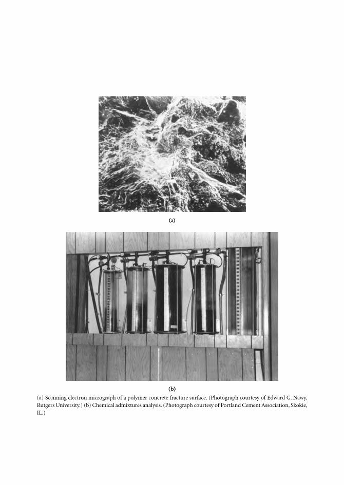
(a) Scanning electron micrograph of a polymer concrete fracture surface. (Photograph courtesy of Edward G. Nawy,Rutgers University.) (b) Chemical admixtures analysis. (Photograph courtesy of Portland Cement Association, Skokie,IL.)
(a)
(b)