Embed Size (px)
Citation preview

Digital Communication System
Chapter 5 : Synchronization
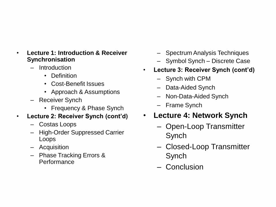
• Lecture 1: Introduction & Receiver Synchronisation
– Introduction
• Definition
• Cost-Benefit Issues
• Approach & Assumptions
– Receiver Synch
• Frequency & Phase Synch
• Lecture 2: Receiver Synch (cont’d)
– Costas Loops
– High-Order Suppressed Carrier Loops
– Acquisition
– Phase Tracking Errors & Performance
– Spectrum Analysis Techniques
– Symbol Synch – Discrete Case
• Lecture 3: Receiver Synch (cont’d)
– Synch with CPM
– Data-Aided Synch
– Non-Data-Aided Synch
– Frame Synch
• Lecture 4: Network Synch
– Open-Loop Transmitter
Synch
– Closed-Loop Transmitter
Synch
– Conclusion
Synchronization Defined
• Phase synchronization.
• Symbol Synchronization.
• Frame Synchronization.
• Frequency Synchronization.
• Network Synchronization.
Tradeoff • There are added cost to receiver design due to
the implementation of acquisition and tracking
circuits.
• Time required for synchronization to be
achieved.
• Energy expended, for instance on pilot signals,
for the purpose of synchronization.
• Complexity due to error control.
– Frame, block, message synchronization.
• Complexity due to spread spectrum technique.
– PN sequence synchronization.
Receiver Synchronization.
• All digital communication receivers require
some degree of synchronization to the
incoming signal.
Frequency and Phase
Synchronization.
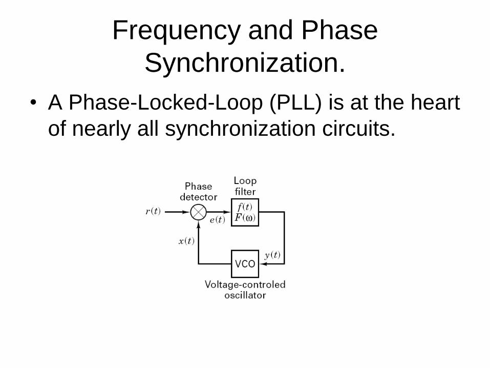
• A Phase-Locked-Loop (PLL) is at the heart
of nearly all synchronization circuits.
Frequency and Phase
Synchronization.
• PLL are servo-control loops, whose
controlled parameter is the phase of a
locally generated replica of the incoming
carrier signal.
• Components of a PLL:
– A phase detector
– A loop filter
– A voltage-controlled oscillator (VCO).
Frequency and Phase
Synchronization.
• A phase detector determines the difference in phase
between the incoming signal and the reference signal.
• The loop filter controls the response of the PLL to the
error signal.
• The VCO is an oscillator whose output frequency is a
linear function of its voltage over some range of input
and output. – +ve signal increase frequency beyond the uncontrolled value.
– -ve signal reduce frequency below the uncontrolled value.
Frequency and Phase
Synchronization.
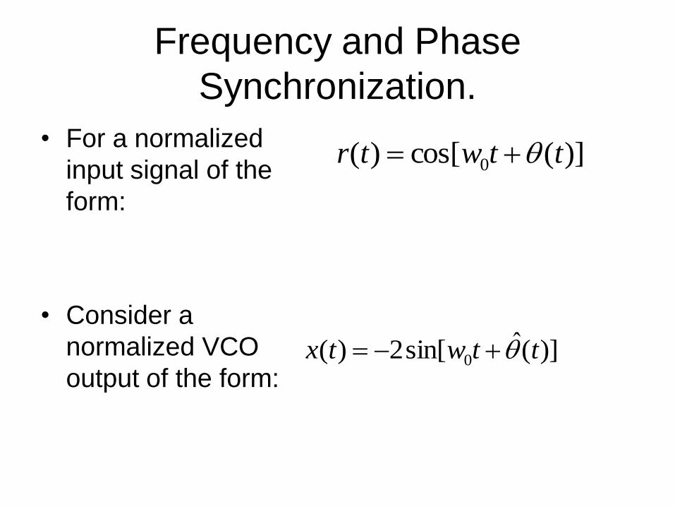
• For a normalized
input signal of the
form:
• Consider a
normalized VCO
output of the form:
)](cos[)( 0 ttwtr
)](ˆsin[2)( 0 ttwtx
Frequency and Phase
Synchronization.
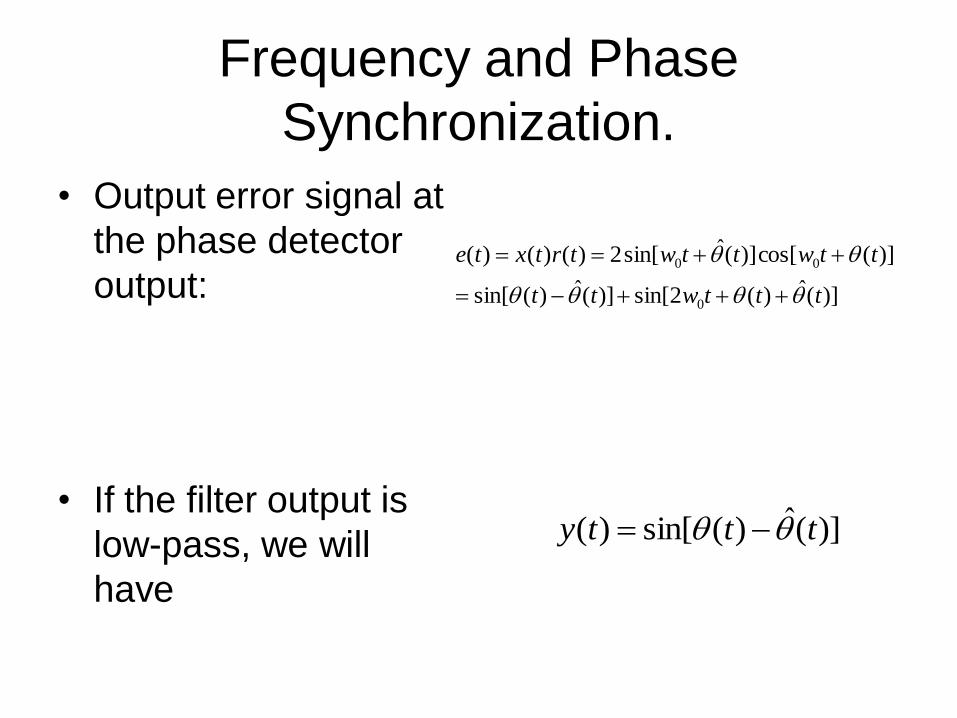
• Output error signal at
the phase detector
output:
• If the filter output is
low-pass, we will
have
)](ˆ)(2sin[)](ˆ)(sin[
)](cos[)](ˆsin[2)()()(
0
00
tttwtt
ttwttwtrtxte
)](ˆ)(sin[)( ttty
Frequency and Phase
Synchronization.
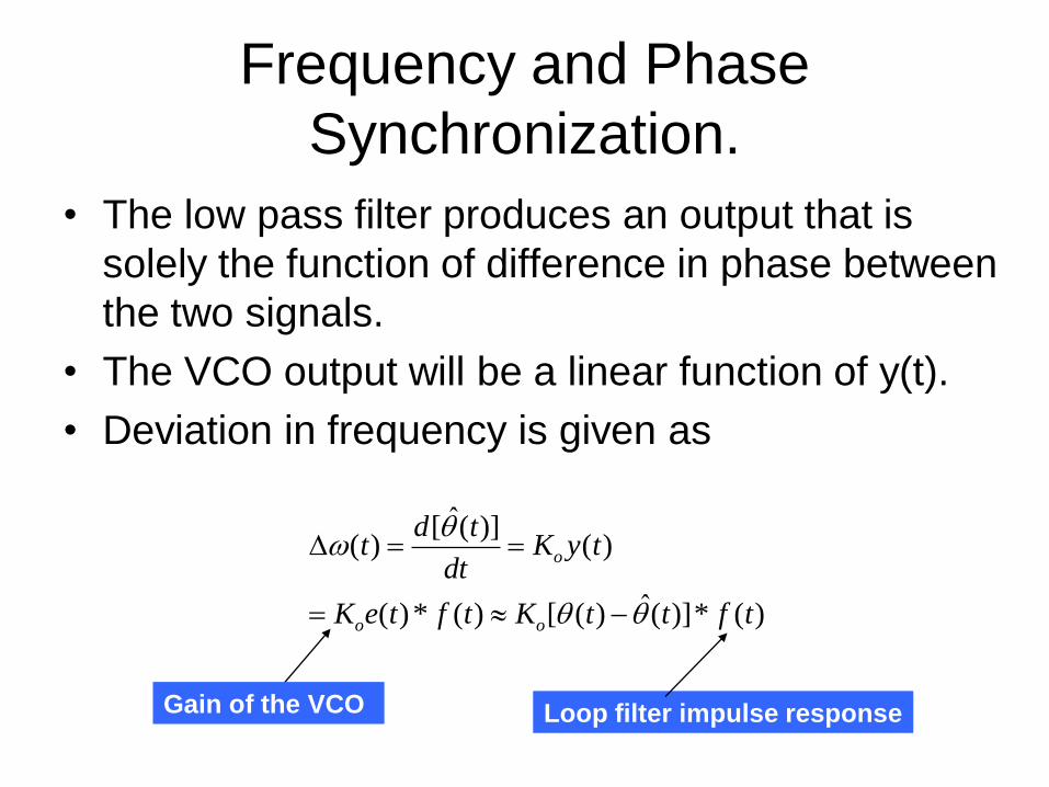
• The low pass filter produces an output that is
solely the function of difference in phase between
the two signals.
• The VCO output will be a linear function of y(t).
• Deviation in frequency is given as
)(*)](ˆ)([)(*)(
)()](ˆ[
)(
tfttKtfteK
tyKdt
tdt
oo
o
Gain of the VCO Loop filter impulse response
Frequency and Phase
Synchronization.
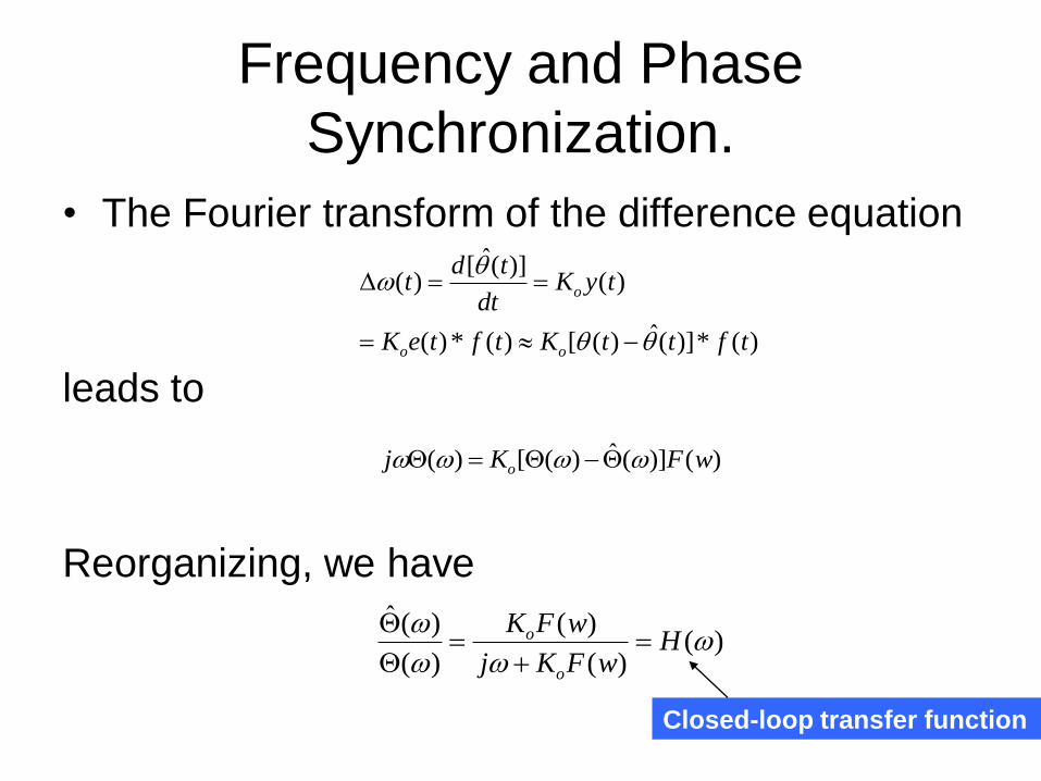
• The Fourier transform of the difference equation
leads to
Reorganizing, we have
)(*)](ˆ)([)(*)(
)()](ˆ[
)(
tfttKtfteK
tyKdt
tdt
oo
o
)()](ˆ)([)( wFKj o
)()(
)(
)(
)(ˆ
H
wFKj
wFK
o
o
Closed-loop transfer function
Frequency and Phase
Synchronization.
• The order of the PLL is the order of the
highest term in jwin the denominator of
H(w).
Steady state tracking Characteristic
of the PLL.
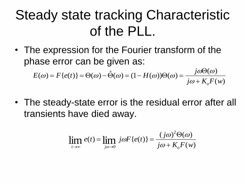
• The expression for the Fourier transform of the
phase error can be given as:
• The steady-state error is the residual error after all
transients have died away.
)(
)()())(1()(ˆ)()}({)(
wFKj
jHteFE
o
)(
)()()}({)(
2
0limlim wFKj
jteFjte
ojt
Performance in noise
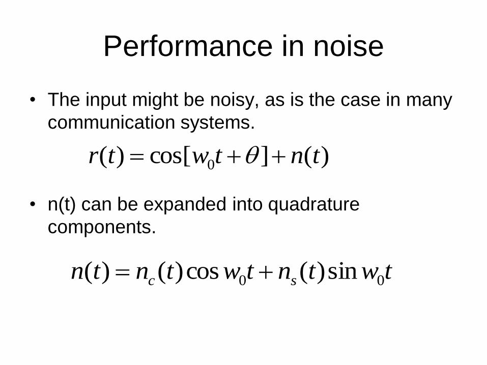
• The input might be noisy, as is the case in many
communication systems.
• n(t) can be expanded into quadrature
components.
)(]cos[)( 0 tntwtr
twtntwtntn sc 00 sin)(cos)()(
Performance in noise
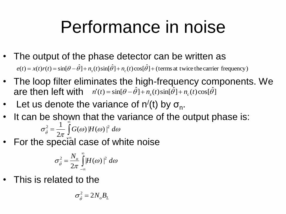
• The output of the phase detector can be written as
• The loop filter eliminates the high-frequency components. We are then left with
• Let us denote the variance of n/(t) by σn.
• It can be shown that the variance of the output phase is:
• For the special case of white noise
• This is related to the
frequency)carrier theat twice terms(]ˆcos[)(]ˆsin[)(]ˆsin[)()()( tntntrtxte cs
]ˆcos[)(]ˆsin[)(]ˆsin[)( tntntn cs
dHG 22
ˆ |)(|)(2
1
dHNo 22
ˆ |)(|2
LoBN22
ˆ
Acqusition.
• Acquisition is the process of getting the
PLL to lock with the incoming signal.
– Aided acquisition
• With the aid of external circuits.
– Self-acqusition
• Without the aid of extrnal signals
Symbol synchronization.
• Symbol synchronization is needed in order to achieve
optimum demodulation.
– Non-Data Aided (NDA).
– Data Aided (DA).
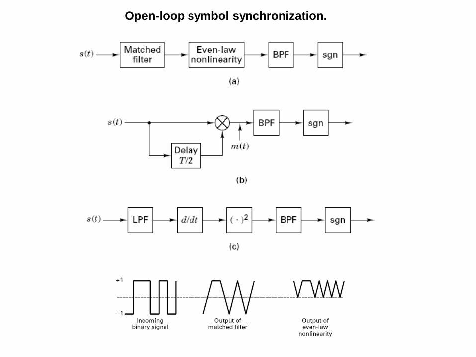
Open-loop symbol synchronization.
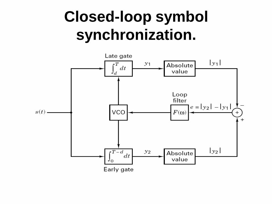
Closed-loop symbol
synchronization.
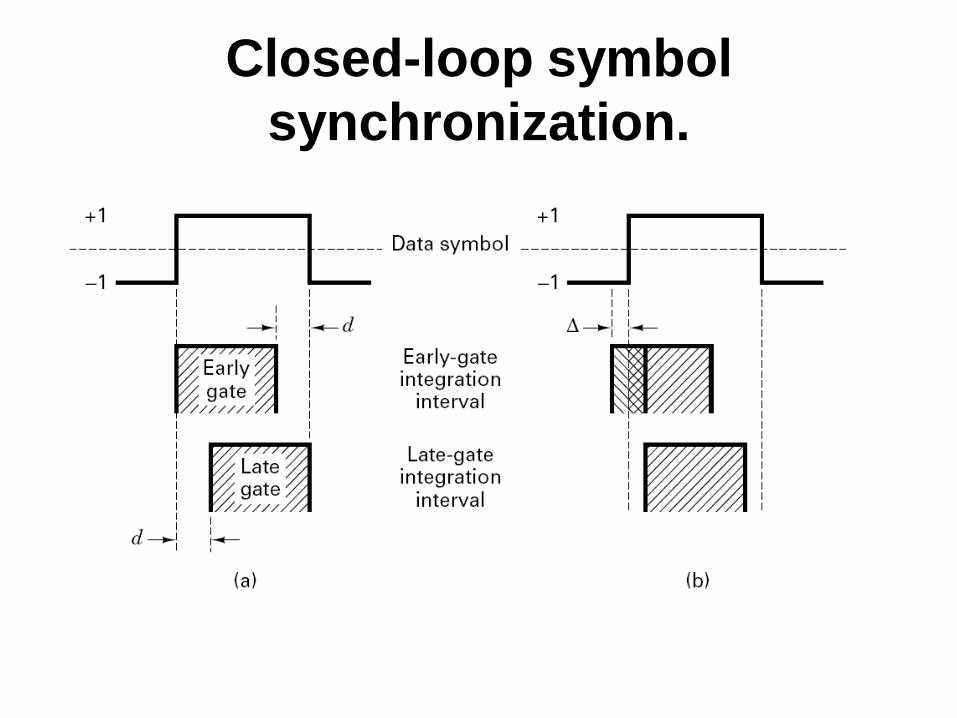
Closed-loop symbol
synchronization.
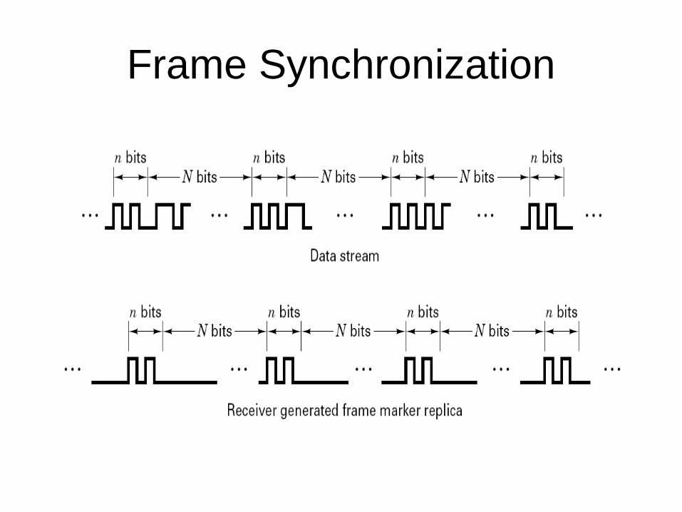
Frame Synchronization