Embed Size (px)
Citation preview

Chem. 133 – 2/17 Lecture

Announcements
• Lab Work– Electronics Lab Report due 2/19– Let me know by today if you plan to do a lab practical
instead– Half of today for more lab lecture with rest as extra half
day to get started on labs• Today’s Lecture
– Operational Amplifiers– Noise
Operational Amplifiers
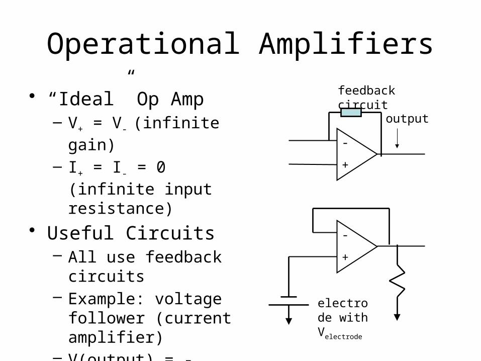
• “Ideal” Op Amp– V+ = V- (infinite gain)
– I+ = I- = 0 (infinite input resistance)
• Useful Circuits– All use feedback
circuits– Example: voltage
follower (current amplifier)
– V(output) = -V(electrode)
+
-
output
feedback circuit
+
-
electrode with Velectrode

Operational Amplifiers
• Other Useful Circuits– Inverting amplifier
• in text• Vout = -RfVin/Rin
• useful for amplifying voltage signals
– Differential amplifier• in text• Vout = (Rf/Rin)(V1 - V2)• allows removal of noise
common to V1/V2
– Current to voltage convertor
• Calculate Vout
+
-
transducer with current I
Rf


NoiseIntroduction
• Why worry about noise?– Both noise and signal affect sensitivity (the
ability to detect low concentrations– While it is easy to increase the signal, noise
often will also increase (e.g. inverting op amp amplifier circuit)
– It is possible to reduce noise without also reducing the signal (e.g. differential op amp amplifier circuit or transducers with internal amplification)
– If we know the source of the noise we can make improvements more easily

NoiseDefinitions
Noise1) “variability in a measurement due to (random) errors”
(textual)
2) the standard deviation in the values (σ)
(mathematical) or the root mean square value (more
common in electronics)
3) peak to peak noise (graphical and roughly 6σ)Peak to Peak Noise
40.00
41.00
42.00
43.00
44.00
45.00
0 0.2 0.4 0.6 0.8 1 1.2
Time (min.)
Vo
ltag
e (m
V)
Peak to peak

NoiseDefinitions
Limit of Detection (also see handout)
- Minimum detectable signal (Smin/N = 3 – may
be defined alternatively)
- Concentration Detection Limit = concentration that gives minimum detectable signal
- Mass/Mole Detection Limit = mass or amount of sample that gives minimum detectable signal

NoiseExample Calculations
Data Set:Measurement of Absorbance of 1.00 mM
Benzoic Acid
Trial Blank Sample1 0.0092 0.02512 0.0108 0.02313 0.0101 0.02274 0.0095 0.0244

NoiseExample Calculation
• Determine:– S/N (both for single measurement and in
average)– Relative standard deviation (%RSD)– Detection Limit
• (do calculations on board)

Signal Averaging
• If the noise is random and well known, repeat measurements improve S/N because signal is additive while noise adds as (n)0.5 (based on propagation of uncertainty rules)
• (S/N)n = [(S/N)n=1]n/(n)0.5 = [(S/N)n=1](n)0.5
Signal Averaging - Question
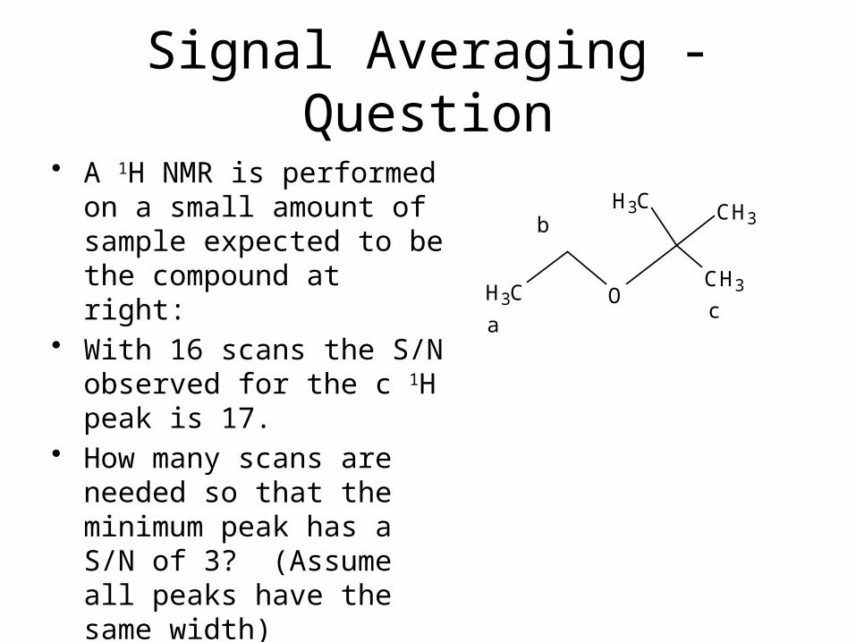
• A 1H NMR is performed on a small amount of sample expected to be the compound at right:
• With 16 scans the S/N observed for the c 1H peak is 17.
• How many scans are needed so that the minimum peak has a S/N of 3? (Assume all peaks have the same width)
CH3CH3 O
CH3 CH3
a
b
c

NoiseSources – Fundamental Types
A. Thermal Noise = Johnson Noise (voltage associated)
- where:kB = Boltzmann’s constant, T = temp. (K), R =
resistance (W), and B = bandwidth (Hz) = range of frequencies accepted
- Solutions: cool devices, use lower R values, reduce bandwidth
B. Shot noise (current associated)
- Solutions: reduce bandwidth, use internally amplified transducers
TRBkV Brmsn 4)(
qIBI rmsn 2)( where q= fundamental charge = 1.6 x 10⁻¹⁹ C and I = current

NoiseSources – Other Types
A. Flicker Noise (or 1/f noise or pink noise)- Occurs at low frequencies- Can result from environmental changes (e.g.
change in light intensity over time, change in temperature)
- Can be reduced through modulating source
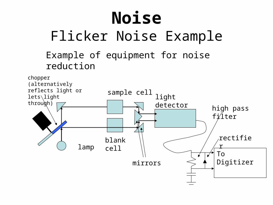
NoiseFlicker Noise Example
lamp
chopper (alternatively reflects light or lets light through)
light detectorsample cell
blank cell
mirrors
Example of equipment for noise reduction
To Digitizer
high pass filter
rectifier

NoiseFlicker Noise Example: Signals
Removal of 1/f Noise
0
50
100
150
200
250
300
0 50 100 150 200 250
Time (s)
Sig
nal
(m
V)
Noise
Mod Sig
light detector signal
High Pass Data
-150
-100
-50
0
50
100
150
0 50 100 150 200 250
Time (s)
Sig
nal
(m
V)
High Pass Data
slow increase in noise over 1st ~100 s
RC Filter only
low f noise removedPositive Only
0
20
40
60
80
100
120
0 50 100 150 200 250
Time (s)
Sig
nal
(m
V)
High Pass Data
RC Filter + diode
Smoothed Low Pass
0
10
20
30
40
50
60
70
80
90
100
0 50 100 150 200 250
Time (s)
Sig
nal
(m
V)
Add. Filtering
Signal following digital filtration