Embed Size (px)
Citation preview

8/7/2019 CIM SEMINAR
http://slidepdf.com/reader/full/cim-seminar 1/46
B y:
SI DDHA R T H KA SHY A P
MT 10 C DM0 0 2
CAD DATA EXCHANGE
AND CAD STANDARDS
8/7/2019 CIM SEMINAR
http://slidepdf.com/reader/full/cim-seminar 2/46
ISSUES
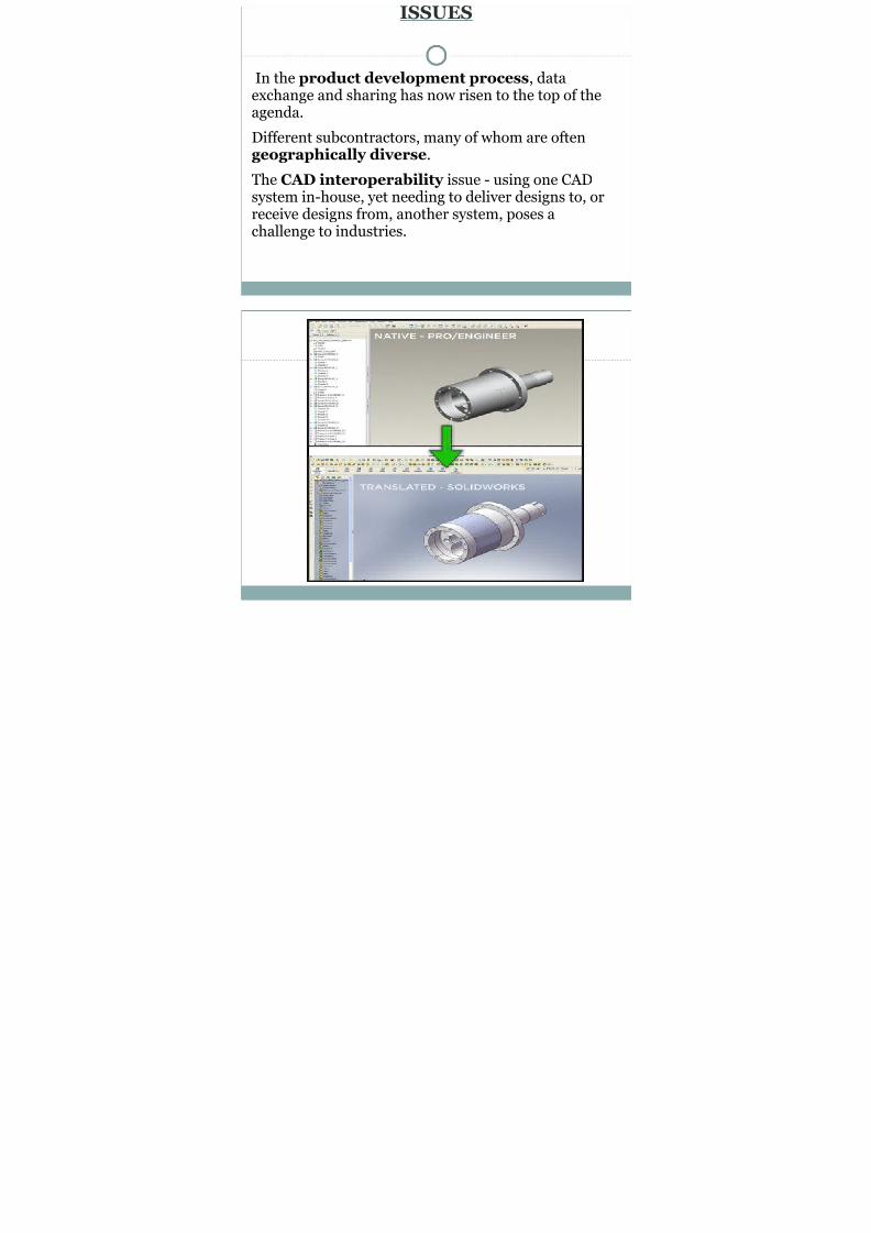
In the product development process, dataexchange and sharing has now risen to the top of theagenda.
Different subcontractors, many of whom are oftengeographically diverse.
The CAD interoperability issue - using one CADsystem in-house, yet needing to deliver designs to, or
receive designs from, another system, poses achallenge to industries.

8/7/2019 CIM SEMINAR
http://slidepdf.com/reader/full/cim-seminar 3/46
8/7/2019 CIM SEMINAR
http://slidepdf.com/reader/full/cim-seminar 4/46
DATA TRANSFER
The format of design data depends on its origin.
Transferring data must embrace the complete productdescription stored in its database.
The various data are GEOMETRIC DATA ,METADATA , DESIGN INTENT DATA andAPPLICATION DATA
Data also depend on different stages of the productlifecycle.

8/7/2019 CIM SEMINAR
http://slidepdf.com/reader/full/cim-seminar 5/46
CAD KERNALS
CAD data formats are governed by the (solid)modeling kernels that the CAD systems are built upon.
A collection of classes and components comprised of
mathematical functions that perform specific modelingtasks.
Ø SOLID MODELING
Ø
CELLULER MODELINGØ FREEFORM SHEET/SURFACE MODELING
8/7/2019 CIM SEMINAR
http://slidepdf.com/reader/full/cim-seminar 6/46
Cont..
Kernel contains functions such as
Ø Creation and editing.
Ø Feature modeling support.
Ø Advanced surfacing, thickening and hollowing,
Ø blending and filleting and sheet modelling.
Ø graphical and rendering support
(hidden-line, wire-frame and drafting).
8/7/2019 CIM SEMINAR
http://slidepdf.com/reader/full/cim-seminar 7/46
WORKING OF CAD KERNEL
The CAD graphic user interface (GUI) interfaces withthe kernel’s functions through so-called applicationuser interface.
Take Parasolid® modelling kernel as an example,which provides 3D digital representation capabilitiesfor NX™, Solid Edge.
8/7/2019 CIM SEMINAR
http://slidepdf.com/reader/full/cim-seminar 8/46

8/7/2019 CIM SEMINAR
http://slidepdf.com/reader/full/cim-seminar 9/46
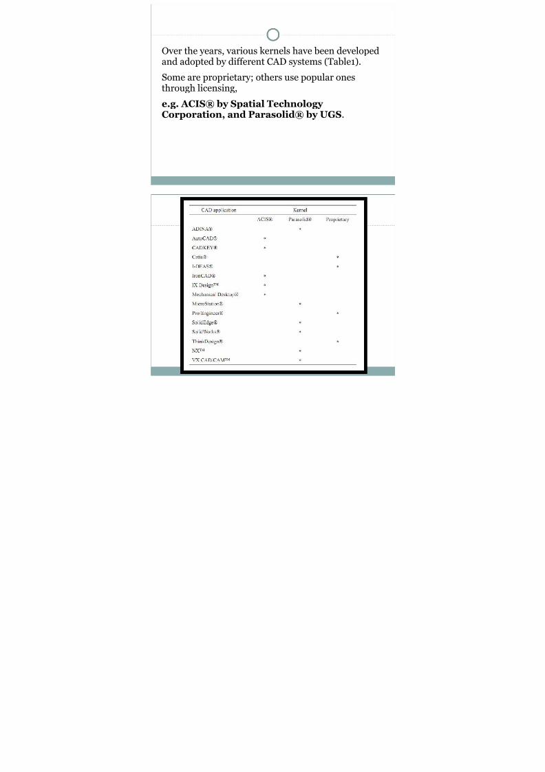
Over the years, various kernels have been developedand adopted by different CAD systems (Table1).
Some are proprietary; others use popular ones
through licensing,e.g. ACIS® by Spatial Technology Corporation, and Parasolid® by UGS.
8/7/2019 CIM SEMINAR
http://slidepdf.com/reader/full/cim-seminar 10/46

8/7/2019 CIM SEMINAR
http://slidepdf.com/reader/full/cim-seminar 11/46
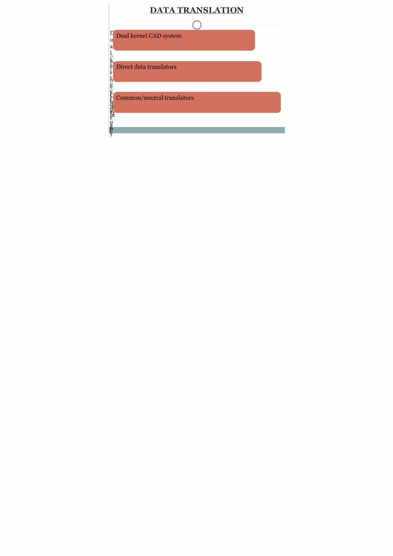
DATA TRANSLATION
Dualk er ne
lCAD
s
Dual kernel CAD system
Dir ec
tdatat
Direct data translators
Commo
n
Common/neutral translators
8/7/2019 CIM SEMINAR
http://slidepdf.com/reader/full/cim-seminar 12/46
DUAL KERNEL CAD SYSTEM
It is a unique technique which puts together twodifferent CAD kernels in one system.
BENEFIT :-
- A bility to work on models developed under eitherkernel
- Combining data from either kernel into a singlemodel.
PROBLEM :-
- Difficult to build
- Multiple kernel types in market

8/7/2019 CIM SEMINAR
http://slidepdf.com/reader/full/cim-seminar 13/46
Cont..
IronCAD®
Ø It is the first dual kernel system which is twincombination of ACIS® and Parasolid®.
Ø Uses both kernels simultaneously, switching back and forth when needed.
Ø The nanosecond switch is usually invisible to theuser.
CAXA™ is a product design and collaborative datamanagement system. Combination of the same two.

8/7/2019 CIM SEMINAR
http://slidepdf.com/reader/full/cim-seminar 14/46
DIRECT DATA TRANSLATORS
Translates the modeling data stored in a productdatabase directly from one CAD system format toan-other in one step.
There exists a neutral database.The neutral database must be general, governed by theminimum required definitions
Independent of any vendor format.

8/7/2019 CIM SEMINAR
http://slidepdf.com/reader/full/cim-seminar 15/46
8/7/2019 CIM SEMINAR
http://slidepdf.com/reader/full/cim-seminar 16/46
Cont..
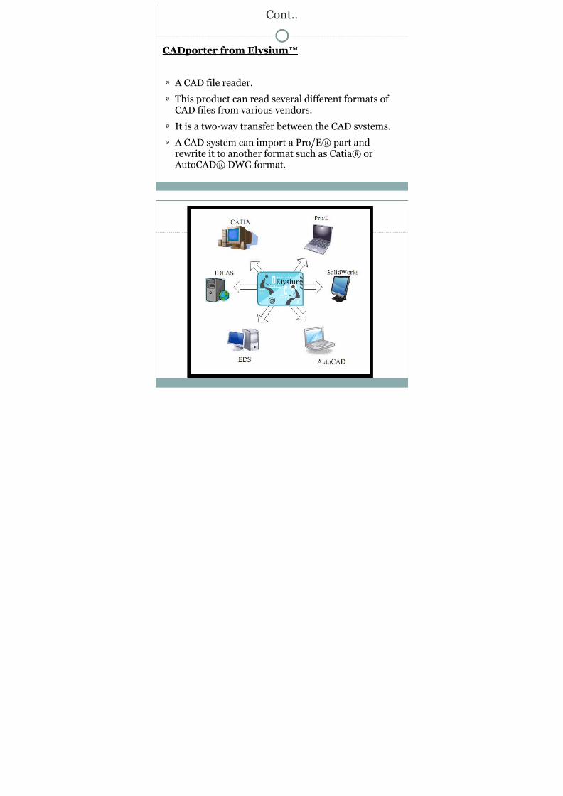
CADporter from Elysium™
Ø A CAD file reader.
Ø This product can read several different formats of CAD files from various vendors.
Ø It is a two-way transfer between the CAD systems.
Ø A CAD system can import a Pro/E® part andrewrite it to another format such as Catia® orAutoCAD® DWG format.

8/7/2019 CIM SEMINAR
http://slidepdf.com/reader/full/cim-seminar 17/46

8/7/2019 CIM SEMINAR
http://slidepdf.com/reader/full/cim-seminar 18/46
NEUTRAL TRANSLATORS
Converts a proprietary CAD data format into a neutraldata format and vice versa, and this neutral data ismade available to the users.
This neutral data format may be of an international orindustry accepted data format or a proprietary dataformat.
There are a few popular industry standards such as,
DXF PDES
XML

8/7/2019 CIM SEMINAR
http://slidepdf.com/reader/full/cim-seminar 19/46
DXF
DXF is the AutoCAD's CAD data file format,developed by Autodesk®.
Enables data interoperability between AutoCAD®
and other programs.Originally introduced in December 1982 as part of AutoCAD® 1.0.
It is primarily a 2D based data format.
The DXF format is a tagged data representation of all the information contained in an AutoCAD®drawing file.

8/7/2019 CIM SEMINAR
http://slidepdf.com/reader/full/cim-seminar 20/46
Organization of DXF file
HEADER section – General information about thedrawing. Each parameter has a variable name and anassociated value.
CLASSES section – Holds the information forapplication defined classes whose instances appear inthe BLOCKS, ENTITIES, and OBJECTS sections of the
database.
8/7/2019 CIM SEMINAR
http://slidepdf.com/reader/full/cim-seminar 21/46
TABLES section – This section contains definitionsof named items. It contains the following tabulateddata:
ü Application ID (APPID)
ü Block Record (BLOCK_RECORD)
ü Dimension Style (DIMSTYPE)
ü
Layer (LAYER)ü Linetype (LTYPE)
ü Text style (STYLE)
ü User Coordinate System (UCS)
8/7/2019 CIM SEMINAR
http://slidepdf.com/reader/full/cim-seminar 22/46
BLOCKS section – Contains Block Definition entitiesdescribing the entities comprising each Block in thedrawing.
ENTITIES section – Contains the drawing entities,including any Block References.
OBJECTS section – Contains the data that apply tonon-graphical objects, used by AutoLISP™ and
ObjectARX® applications.THUMBNAILIMAGE section – Contains thepreview image for the DXF file.
END OF FILE

8/7/2019 CIM SEMINAR
http://slidepdf.com/reader/full/cim-seminar 23/46
IGES
Originated in the late 1970’s.
Treats the product definition as a file of entities. Eachentity is represented in an application-independent
format.To and from which the native representation of aspecific CAD/CAM system can be mapped.
Entities
Ø Geometric.
Ø Non-geometric.

8/7/2019 CIM SEMINAR
http://slidepdf.com/reader/full/cim-seminar 24/46
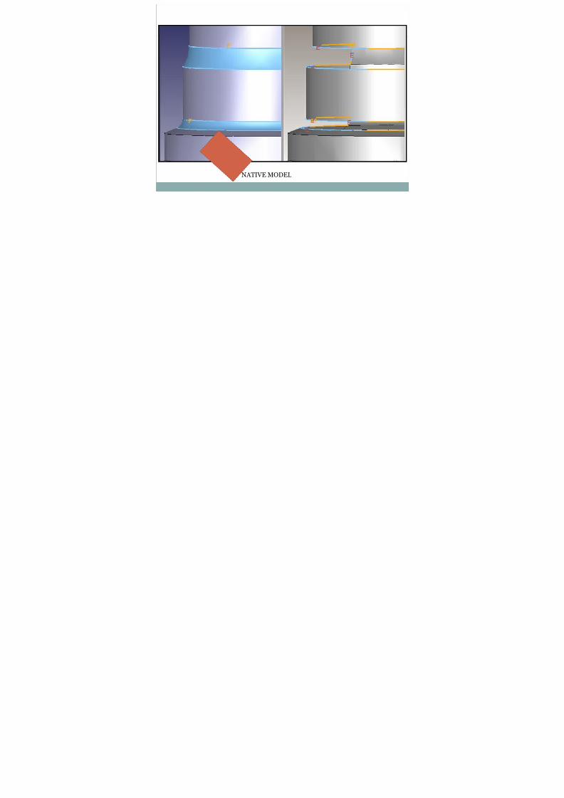
NATIVE MODEL

8/7/2019 CIM SEMINAR
http://slidepdf.com/reader/full/cim-seminar 25/46
Cont..
Geometry entities define a physical shape
Points--curves--surfaces--solids--relations.
Non-geometry entities serve to provide:
1) A viewing perspective in which a planar drawingmay be composed
2) Annotation and dimensioning appropriate to the
drawing.3) Specific attributes or characteristics for individual
or groups of entities.
8/7/2019 CIM SEMINAR
http://slidepdf.com/reader/full/cim-seminar 26/46
IG
ES
● STA R
T
● GLOBAL
● DIRECTORY ENTRY
● PARAMETER DATA
● TERMINATE
8/7/2019 CIM SEMINAR
http://slidepdf.com/reader/full/cim-seminar 27/46
Cont..
Transfer both 2D and 3D finite elements.
LACKS A MEANS OF TRANSFERRING SOLIDOBJECTS.
Entities can be added but they are not standardized to be acceptable across all CAD systems.
8/7/2019 CIM SEMINAR
http://slidepdf.com/reader/full/cim-seminar 28/46
PDES
Product Data Exchange Specification.
PDES was designed to completely define a product forall applications over its expected life cycle.
PDES is designed to be informationally complete forall downstream applications and to be directly interpretable by these applications.
8/7/2019 CIM SEMINAR
http://slidepdf.com/reader/full/cim-seminar 29/46
Cont..
The main types of data which are used in PDES todescribe a product include,
1) Administrative and Control data
2) Geometry such as points, curves and surfaces
3) Topology such as vertices, loops and faces
4) Tolerances
5) Form Features
6) Attributes such as surface finish
7) Material Properties
8) Part Assemblies

8/7/2019 CIM SEMINAR
http://slidepdf.com/reader/full/cim-seminar 30/46
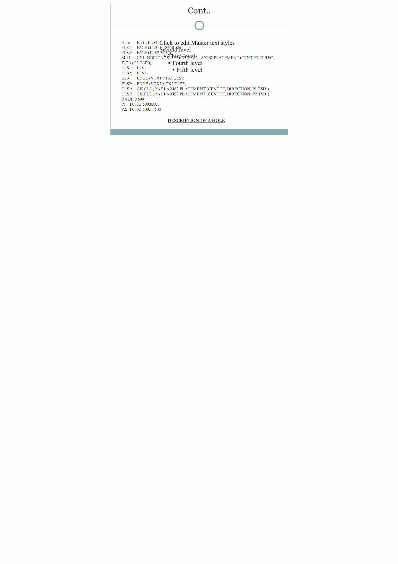
Cont..
Click to edit Master text stylesSecond level● Third level●
Fourth level● Fifth level
DESCRIPTION OF A HOLE
8/7/2019 CIM SEMINAR
http://slidepdf.com/reader/full/cim-seminar 31/46
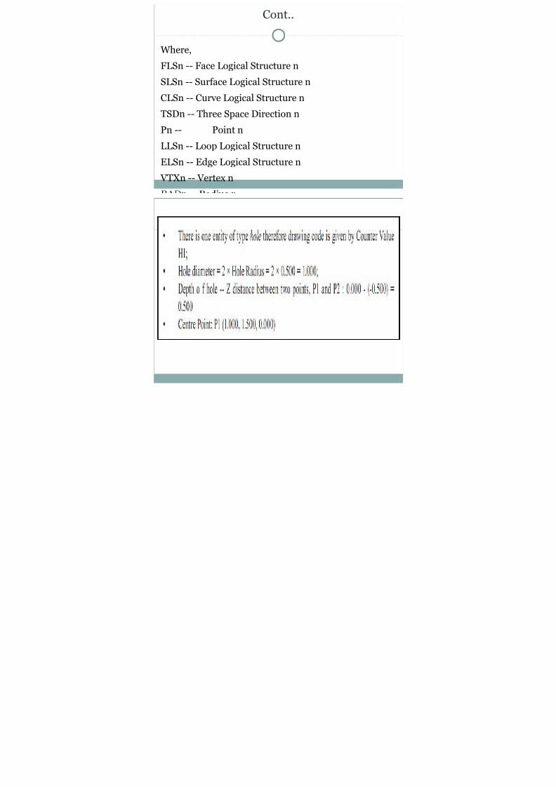
Cont..
Where,
FLSn -- Face Logical Structure n
SLSn -- Surface Logical Structure n
CLSn -- Curve Logical Structure n
TSDn -- Three Space Direction n
Pn -- Point n
LLSn -- Loop Logical Structure n
ELSn -- Edge Logical Structure n
VTXn -- Vertex n

8/7/2019 CIM SEMINAR
http://slidepdf.com/reader/full/cim-seminar 32/46

8/7/2019 CIM SEMINAR
http://slidepdf.com/reader/full/cim-seminar 33/46
STEP
ISO 10303 is an ISO standard for the computer-interpretable representation and exchange of product manufacturing information.
Its official title is: Automation systems and integration Product data representationand exchange.
It is known informally as "STEP"
(Standard For The Exchange Of Product ModelData)

8/7/2019 CIM SEMINAR
http://slidepdf.com/reader/full/cim-seminar 34/46
DATA EXCHANGE● Define data form.● Hold a copy.● Transitory data.
DATA SHARING● Same copy access.● Operation at same time.
DATA ARCHIVING● Data as per standard kept for future use

8/7/2019 CIM SEMINAR
http://slidepdf.com/reader/full/cim-seminar 35/46
COMPONENTS OF STEPARCHITECTURE

8/7/2019 CIM SEMINAR
http://slidepdf.com/reader/full/cim-seminar 36/46
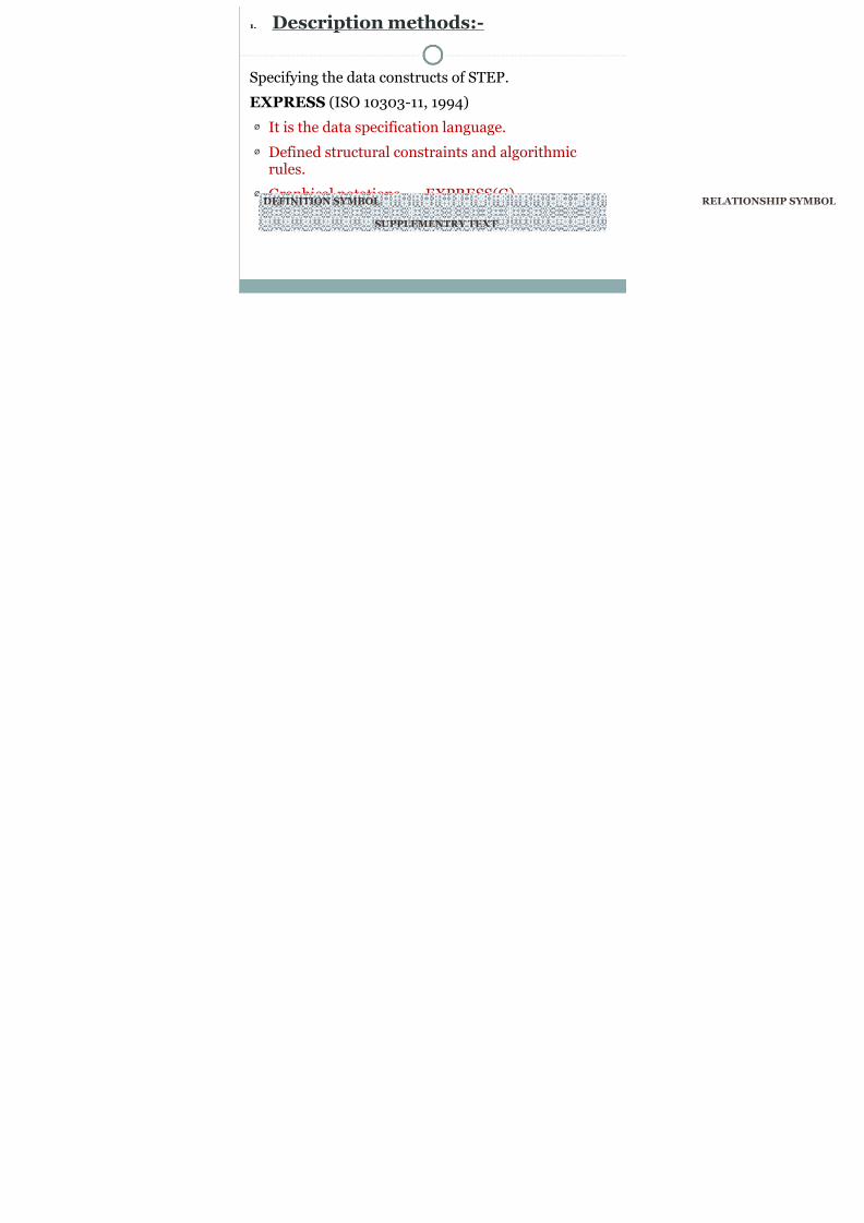
1. Description methods:-
Specifying the data constructs of STEP.
EXPRESS (ISO 10303-11, 1994)
Ø It is the data specification language.
Ø Defined structural constraints and algorithmicrules.
Ø Graphical notations EXPRESS(G)
DEFINITION SYMBOL
SUPPLEMENTRY TEXT

8/7/2019 CIM SEMINAR
http://slidepdf.com/reader/full/cim-seminar 37/46
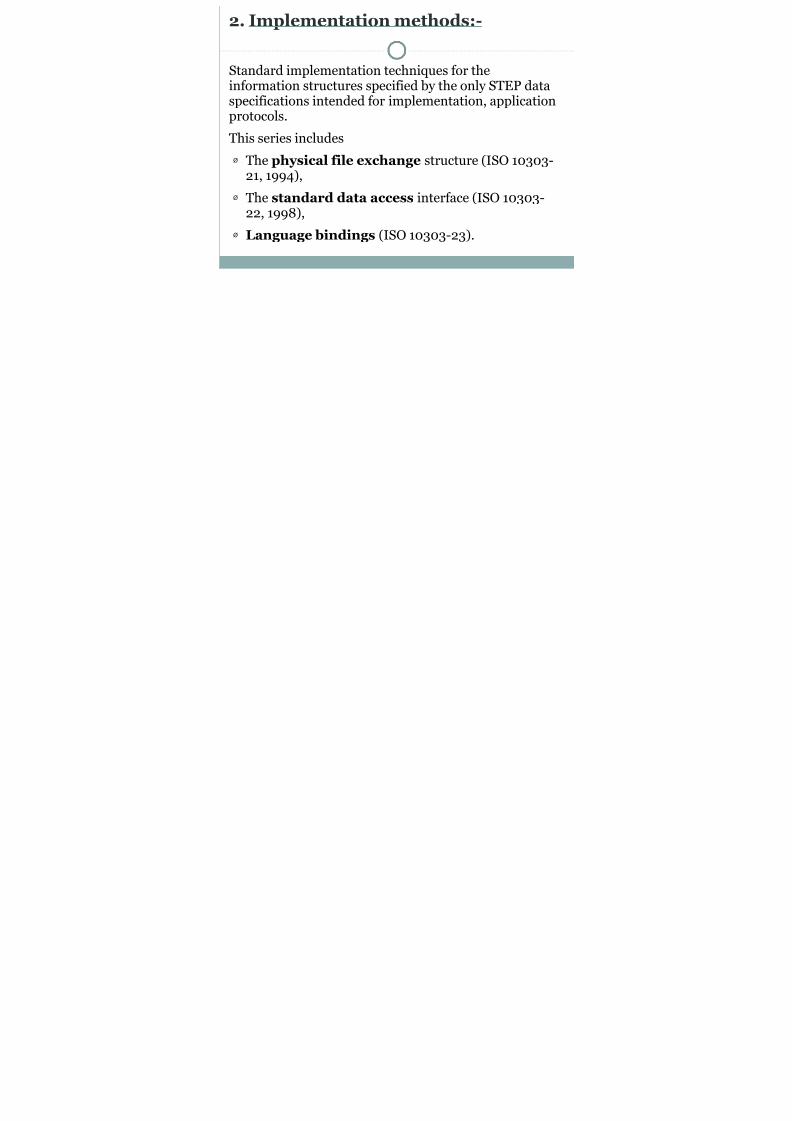
2. Implementation methods:-
Standard implementation techniques for theinformation structures specified by the only STEP dataspecifications intended for implementation, applicationprotocols.
This series includes
Ø The physical file exchange structure (ISO 10303-21, 1994),
Ø The standard data access interface (ISO 10303-22, 1998),
Ø Language bindings (ISO 10303-23).

8/7/2019 CIM SEMINAR
http://slidepdf.com/reader/full/cim-seminar 38/46
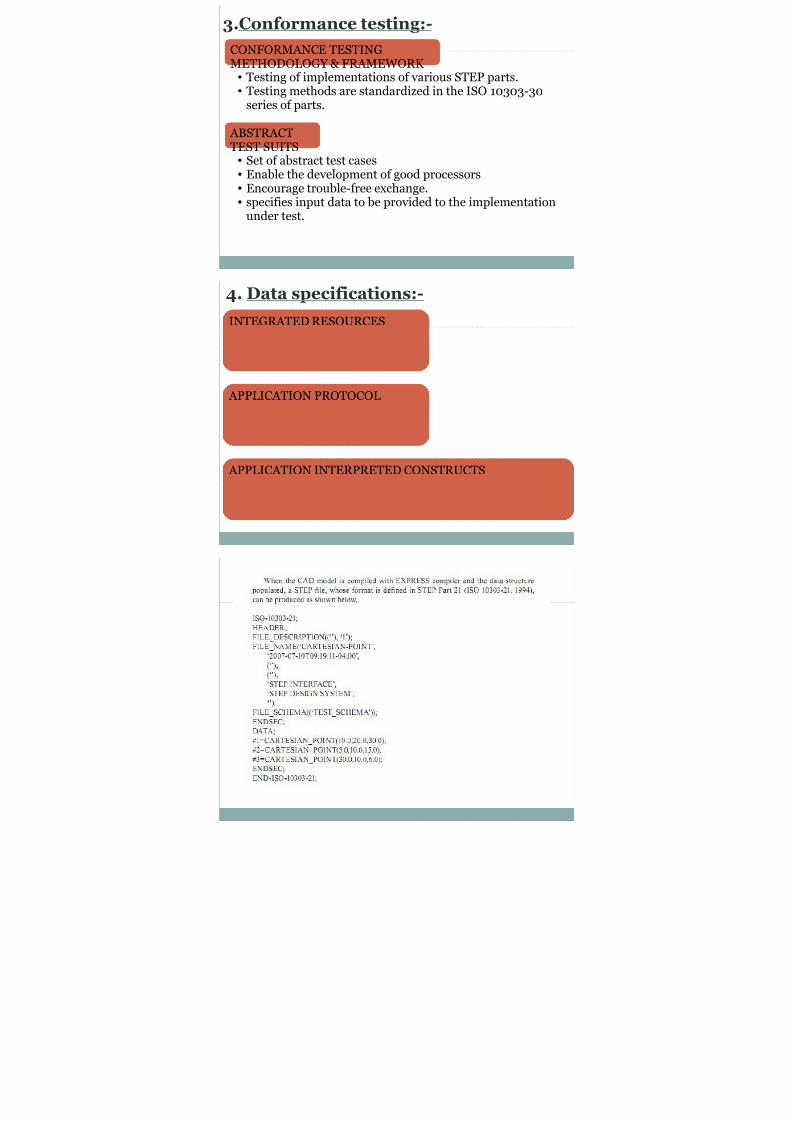
3.Conformance testing:-
CONFORMANCE TESTING
METHODOLOGY & FRAMEWORK ● Testing of implementations of various STEP parts.● Testing methods are standardized in the ISO 10303-30
series of parts.
ABSTRACTTEST SUITS● Set of abstract test cases● Enable the development of good processors● Encourage trouble-free exchange.● specifies input data to be provided to the implementation
under test.
D ifi i

8/7/2019 CIM SEMINAR
http://slidepdf.com/reader/full/cim-seminar 39/46
INTEGRATED RESOURCES
APPLICATION PROTOCOL
APPLICATION INTERPRETED CONSTRUCTS
4. Data specifications:-

8/7/2019 CIM SEMINAR
http://slidepdf.com/reader/full/cim-seminar 40/46

8/7/2019 CIM SEMINAR
http://slidepdf.com/reader/full/cim-seminar 41/46
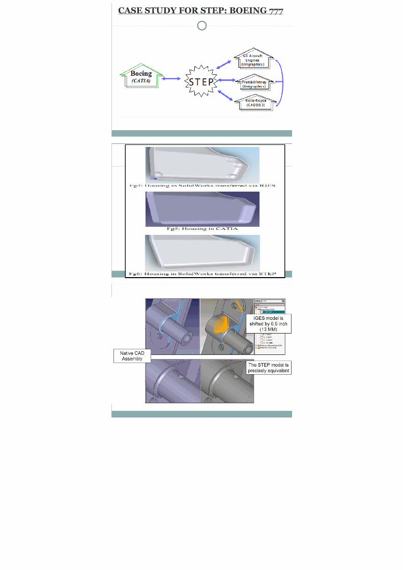
CASE STUDY FOR STEP: BOEING 777

8/7/2019 CIM SEMINAR
http://slidepdf.com/reader/full/cim-seminar 42/46

8/7/2019 CIM SEMINAR
http://slidepdf.com/reader/full/cim-seminar 43/46

8/7/2019 CIM SEMINAR
http://slidepdf.com/reader/full/cim-seminar 44/46
COMAPRISON
Click to edit Master text stylesSecond level● Third level● Fourth level●
Fifth level
C S

8/7/2019 CIM SEMINAR
http://slidepdf.com/reader/full/cim-seminar 45/46
REFERENCES
Integrating Advanced Computer-Aided Design,Manufacturing, and Numerical Control:Principles and Implementations by XUN XU.
Barequet, G. (1997). Using geometric hashing to repairCAD objects. IEEE Computational Science &Engineering, 4(4), 22-28
Barequet, G., & Duncan, C. A. (1998). RSVP: A
geometric toolkit for controlled repair of solid models.IEEE Transactions on Visualization And ComputerGraphics, 4(2), 162-177
Bloor, S., & Owen, J. (2003). Product Data Exchange.
UK: Taylor & Francis.

8/7/2019 CIM SEMINAR
http://slidepdf.com/reader/full/cim-seminar 46/46
THANK YOU