Embed Size (px)
Citation preview
1
Progress of Theoretical Physics, Vol. 125, No. 3, March 2011
Clustering of Non-Identical Clocks
Krzysztof Czo�lczynski, Przemys�law Perlikowski,Andrzej Stefanki and Tomasz Kapitaniak
Division of Dynamics, Technical University of Lodz,Stefanowskiego 1/15, 90-924 Lodz, Poland
(Received August 27, 2010; Revised January 16, 2011)
We study synchronization of a number of different pendulum clocks hanging from ahorizontal beam which can roll on the parallel surface. The results previously obtained for nidentical clocks [Czolczynski et al., Prog. Theor. Phys. 122 (2009), 1027] are generalized forthe case of non-identical clocks. Pendula have the same period of oscillations so the clocks areaccurate but have different masses. It has been shown that after a transient, different typesof synchronization between pendula can be observed; (i) the complete synchronization inwhich all pendula behave identically, (ii) pendula create three or five clusters of synchronizedpendula. Contrary to the case of identical clocks antiphase synchronization in pairs is notrobust for an even number of clocks. We derive the equations for the estimation of the phasedifferences between phase synchronized clusters. The evidence, why other configurationswith a different number of clusters are not observed, is given.
Subject Index: 034
§1. Introduction
The problem of the synchronization of clocks can be traced back to the Dutchresearcher Christian Huygens in the 17th century.1)–4) He showed that a couple ofmechanical clocks hanging from a common support had been synchronized. Huy-gens had found the pendulum clocks swung in exactly the same frequency and out ofphase, i.e., in antiphase synchronization (phase difference equals π). After the exter-nal perturbation, the antiphase state was restored within half an hour and remainedindefinitely.
Recently, Huygens’ experiment has attracted increasing attention from differentresearch groups.5)–14) Pogromsky et al.5) designed a controller for synchronizationproblem for two pendula suspended on an elastically supported rigid beam. To ex-plain Huygens’ observations Bennett et al.6) built an experimental device consistingof two interacting pendulum clocks hanged on a heavy support which was mountedon a low-friction wheeled cart. The device moves by the action of the reaction forcesgenerated by the swing of two pendula and the interaction of the clocks occurs dueto the motion of the clocks’ base. It has been shown that to repeat Huygens’ re-sults, the high precision (the precision that Huygens certainly could not achieve) isnecessary. Senator7) developed a qualitative approximate theory of clocks’ synchro-nization. This theory explicitly includes the essential nonlinear elements of Huygens’system, i.e., escapement mechanisms but also includes many simplifications. An in-teraction mechanism between two oscillators leading to exact antiphase and in-phasesynchronization has been described by Dilao.8) It has been shown that if two cou-
2 K. Czo�lczynski, P. Perlikowski, A. Stefanki and T. Kapitaniak
pled nonlinear oscillators reach the antiphase or the in-phase synchronization, theoscillation frequency is different from the frequency of the uncoupled oscillators.
A device mimicking Huygens’ clock experiment, the so-called “coupled pendulaof the Kumamoto University”,9) consists of two pendula whose suspension rods areconnected by a weak spring, and one of the pendula is excited by an external rotor.The numerical results of Fradkov and Andrievsky10) show simultaneous approximatein-phase and antiphase synchronization. Both types of synchronization can be ob-tained for different initial conditions. Additionally, it has been shown that for smalldifference in the pendula frequencies they may not synchronize.
A very simple demonstration device was built by Pantaleone.11) It consists oftwo metronomes located on a freely moving light wooden base. The base lies ontwo empty soda cans which smoothly roll on the table. Both in-phase and antiphasesynchronizations of the metronomes have been observed. Recently, Ulrichs et al.12)
have studied synchronization scenarios of coupled mechanical metronomes showingthe onset of synchronization for two, three, and 100 globally coupled metronomes.
In the previous papers12),13) we studied a synchronization problem for n identicalpendulum clocks hanging from an elastically fixed horizontal beam. It was assumedthat each pendulum performs a periodic motion which starts from different initialconditions. We showed that after a transient different types of synchronization be-tween pendula can be observed. The first type is in-phase complete synchronizationin which all pendula behave identically. In the second type one can identify thegroups (clusters) of synchronized pendula. We showed that only configurations ofthree and five clusters are possible and derive algebraic equations for the phase dif-ference between the pendula in different clusters. In the third type, which is possibleonly for even n, one observes anti-phase synchronization in n/2 pairs of pendula.Besides these synchronized states it is possible to observe the uncorrelated motionof the pendula.
In this paper we generalize these results for the case of n non-identical pendu-lum clocks. It has been assumed that the clocks under consideration are accurate,i.e., show exactly the same time, but can differ by the design of the escapementmechanism and the pendulum. Particularly, we consider the pendula with the sameperiod of oscillations and different masses. Our main result shows that the phasesynchronization of non-identical clocks is possible only when three or five clustersare created. Contrary to the case of identical clocks this result holds for both evenand odd number of clocks. We derive the equations which allow the estimation ofthe phase differences between clusters. We argue why other cluster configurationsare not possible.
The paper is organized as follows. In §2 we present our theoretical modelwhich describes the dynamics of n coupled non-identical pendulum clocks. Sec-tion 3 presents the results of our numerical studies. We present typical examplesof stable phase synchronization in the considered system, associated with pendulaconfigurations and derive equations for estimation of the phase shifts between thependula. Here we give evidence why one can observe configurations of only three orfive clusters. Finally, we discuss why the other configurations are not possible andsummarize our results in §4.
Clustering of Non-Identical Clocks 3
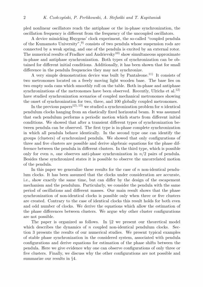
Fig. 1. The model of n pendulum clocks hanging from a horizontal beam.
§2. The model
In the current studies we consider a system shown in Fig. 1. The beam of massM can move in the horizontal direction x. The beam supports n pendulum clockswith pendula of the same length l, identical period of oscillations T (due to the smallamplitudes of the clocks’ pendula15)) and different masses mi(i = 1, 2, . . .). Underthese assumptions the clocks are accurate, i.e., when uncoupled show exactly thesame time but can be different by the design of the pendulum and the escapementmechanism. The position of the i-th pendulum is given by a variable ϕi and itsoscillations are damped by the viscous friction described by damping coefficientcϕi. We assume that this friction is proportional to the pendulum mass mi, i.e.,cϕi = cϕmi and the length of the pendula l is equal to g/4π2= 0.2485 [m], where gis a gravitational acceleration. The beam is considered as a rigid body so the elasticwaves along it are not considered. We describe the phenomena which take place farbelow the resonances for both longitudinal and transverse oscillations of the beam.
The system equations can be written in a form of Euler-Lagrange equations:
mil2ϕi + mixl cos ϕi + cϕmiϕi + migl sin ϕi = MDi, (1)(
M +n∑
i=1
mi
)x +
n∑i=1
(milϕi cos ϕi − milϕ
2i sin ϕi
)= 0. (2)
The clock escapement mechanism (described in details in 13)) represented by mo-mentum MDi provides the energy needed to compensate the energy dissipation dueto the viscous friction cϕi and to keep the clocks running.15) This mechanism acts intwo successive steps (the first step is followed by the second one and the second oneby the first one). In the first step if ϕi < γN then MDi = MNi and when ϕi < 0 thenMDi = 0, where γN and MNi are constant values which characterize the mechanism.For the second stage one has for −γN < ϕi < 0 MDi = −MNi and for ϕi > 0 MDi
= 0. In the undamped (cϕi = 0) and unforced (MDi = 0) case when the beam Mis at rest (x = 0) each pendulum oscillates with the period T equal to 1.0 [s] andfrequency α = 2π [s−1]. Under these assumptions the dynamics of the pendulumclock is described by a self-excited oscillator with a limit cycle16) (see also Ref. 17)).The dynamics of the other type of clock escapement mechanism, i.e., verge and foliot
4 K. Czo�lczynski, P. Perlikowski, A. Stefanki and T. Kapitaniak
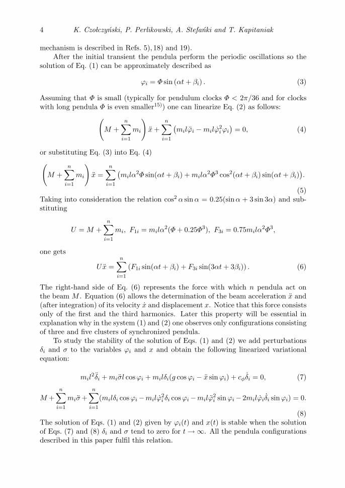
mechanism is described in Refs. 5), 18) and 19).After the initial transient the pendula perform the periodic oscillations so the
solution of Eq. (1) can be approximately described as
ϕi = Φ sin (αt + βi) . (3)
Assuming that Φ is small (typically for pendulum clocks Φ < 2π/36 and for clockswith long pendula Φ is even smaller15)) one can linearize Eq. (2) as follows:(
M +n∑
i=1
mi
)x +
n∑i=1
(milϕi − milϕ
2i ϕi
)= 0, (4)
or substituting Eq. (3) into Eq. (4)(M +
n∑i=1
mi
)x =
n∑i=1
(milα
2Φ sin(αt + βi) + milα2Φ3 cos2(αt + βi) sin(αt + βi)
).
(5)Taking into consideration the relation cos2 α sin α = 0.25(sin α + 3 sin 3α) and sub-stituting
U = M +n∑
i=1
mi, F1i = milα2(Φ + 0.25Φ3), F3i = 0.75milα
2Φ3,
one gets
Ux =n∑
i=1
(F1i sin(αt + βi) + F3i sin(3αt + 3βi)) . (6)
The right-hand side of Eq. (6) represents the force with which n pendula act onthe beam M . Equation (6) allows the determination of the beam acceleration x and(after integration) of its velocity x and displacement x. Notice that this force consistsonly of the first and the third harmonics. Later this property will be essential inexplanation why in the system (1) and (2) one observes only configurations consistingof three and five clusters of synchronized pendula.
To study the stability of the solution of Eqs. (1) and (2) we add perturbationsδi and σ to the variables ϕi and x and obtain the following linearized variationalequation:
mil2δi + miσl cos ϕi + milδi(g cos ϕi − x sin ϕi) + cφδi = 0, (7)
M +n∑
i=1
miσ +n∑
i=1
(milδi cos ϕi −milϕ2i δi cos ϕi −milϕ
2i sin ϕi − 2milϕiδi sin ϕi) = 0.
(8)The solution of Eqs. (1) and (2) given by ϕi(t) and x(t) is stable when the solutionof Eqs. (7) and (8) δi and σ tend to zero for t → ∞. All the pendula configurationsdescribed in this paper fulfil this relation.
Clustering of Non-Identical Clocks 5
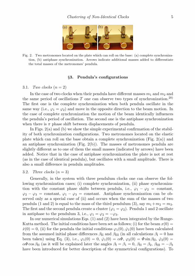
Fig. 2. Two metronomes located on the plate which can roll on the base: (a) complete synchroniza-
tion, (b) antiphase synchronization. Arrows indicate additional masses added to differentiate
the total masses of the metronomes’ pendula.
§3. Pendula’s configurations
3.1. Two clocks (n = 2)
In the case of two clocks when their pendula have different masses m1 and m2 andthe same period of oscillations T one can observe two types of synchronization.20)
The first one is the complete synchronization when both pendula oscillate in thesame way (i.e., ϕ1 = ϕ2) and move in the opposite direction to the beam motion. Inthe case of complete synchronization the motion of the beam identically influencesthe pendula’s period of oscillation. The second one is the antiphase synchronizationwhen there is π phase shift between displacements of pendula.
In Figs. 2(a) and (b) we show the simple experimental confirmation of the stabil-ity of both synchronization configurations. Two metronomes located on the elasticplate which can roll on the base obtain a complete synchronization (Fig. 2(a)) andan antiphase synchronization (Fig. 2(b)). The masses of metronomes pendula areslightly different as to one of them the small masses (indicated by arrows) have beenadded. Notice that in the case of antiphase synchronization the plate is not at rest(as in the case of identical pendula), but oscillates with a small amplitude. There isalso a small difference in pendula amplitudes.
3.2. Three clocks (n = 3)
Generally, in the system with three pendulum clocks one can observe the fol-lowing synchronization cases; (i) complete synchronization, (ii) phase synchroniza-tion with the constant phase shifts between pendula, i.e., ϕ1 − ϕ2 = constant,ϕ2 − ϕ3 = constant, ϕ1 − ϕ3 = constant. Antiphase synchronization can be ob-served only as a special case of (ii) and occurs when the sum of the masses of twopendula (1 and 2) is equal to the mass of the third pendulum (3), say m1 +m2 = m3.The first and the second pendula create a cluster (ϕ1 = ϕ2). Pendula 1 and 2 oscillatein antiphase to the pendulum 3, i.e., ϕ1 = ϕ2 = −ϕ3.
In our numerical simulations Eqs. (1) and (2) have been integrated by the Runge-Kutta method. The initial conditions have been set as follows; (i) for the beam x(0) =x(0) = 0, (ii) for the pendula the initial conditions ϕ1(0), ϕ1(0) have been calculatedfrom the assumed initial phase differences βII and βIII (in all calculations βI = 0 hasbeen taken) using Eq. (3), i.e., ϕ1(0) = 0, ϕ1(0) = αΦ, ϕ2(0) = Φ sin βII, ϕ2(0) =αΦ cos βII (as it will be explained later the angles βI = β1 = 0, βII = β2, βIII = −β3
have been introduced for better description of the symmetrical configurations). To
6 K. Czo�lczynski, P. Perlikowski, A. Stefanki and T. Kapitaniak
prove the stability of the obtained configurations we used Eqs. (7) and (8).Stable configurations of the pendula can be visualized in the following maps.
We plot the position of each pendulum given by Eqs. (1) and (2) (after decay of thetransients) in the phase space ϕi, ϕi at the time when the first pendulum is movingthrough the equilibrium position ϕ1 = 0 with the positive velocity ϕ1 > 0. After theinitial transients the pendula perform periodic oscillations, which are visible in suchmaps by a single point for each pendulum (for better visibility indicated as a blackdot). As the pendula oscillate with the same amplitude the distance of each point tothe origin (0, 0) is equal. The lines between these points and the origin are equal tothe phase differences βi between the oscillations of the pendula. White circle aroundthe group of pendula indicates that the cluster of synchronized pendula has beencreated.
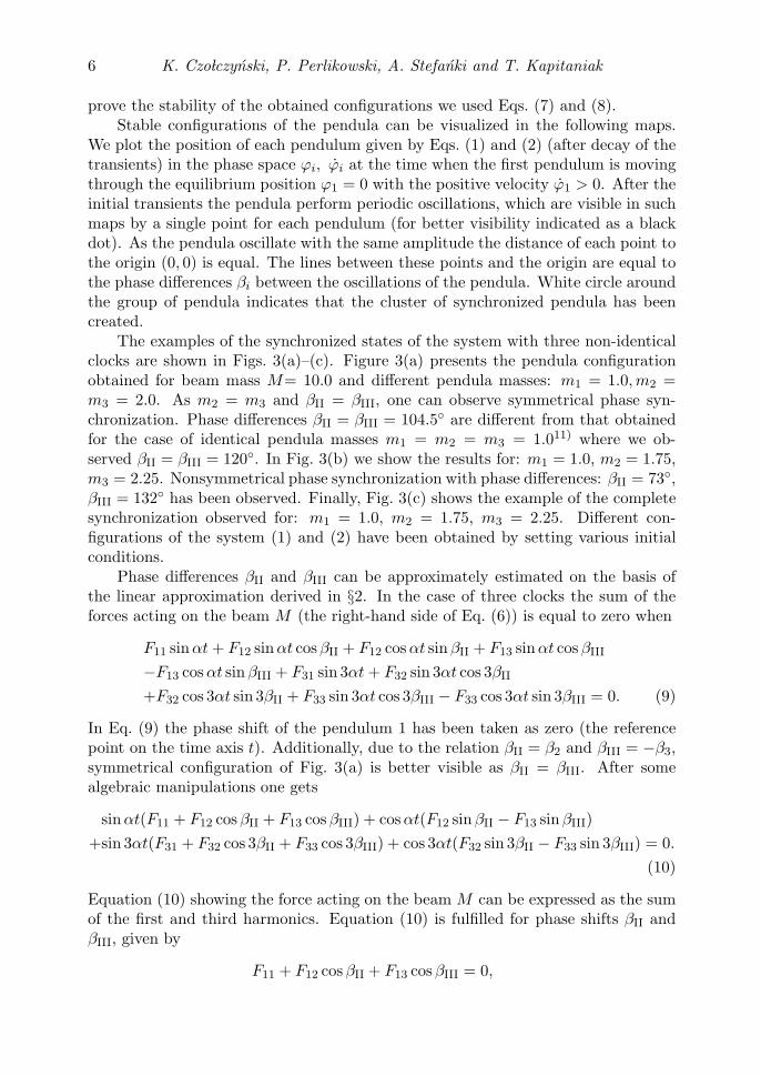
The examples of the synchronized states of the system with three non-identicalclocks are shown in Figs. 3(a)–(c). Figure 3(a) presents the pendula configurationobtained for beam mass M= 10.0 and different pendula masses: m1 = 1.0, m2 =m3 = 2.0. As m2 = m3 and βII = βIII, one can observe symmetrical phase syn-chronization. Phase differences βII = βIII = 104.5◦ are different from that obtainedfor the case of identical pendula masses m1 = m2 = m3 = 1.011) where we ob-served βII = βIII = 120◦. In Fig. 3(b) we show the results for: m1 = 1.0, m2 = 1.75,m3 = 2.25. Nonsymmetrical phase synchronization with phase differences: βII = 73◦,βIII = 132◦ has been observed. Finally, Fig. 3(c) shows the example of the completesynchronization observed for: m1 = 1.0, m2 = 1.75, m3 = 2.25. Different con-figurations of the system (1) and (2) have been obtained by setting various initialconditions.
Phase differences βII and βIII can be approximately estimated on the basis ofthe linear approximation derived in §2. In the case of three clocks the sum of theforces acting on the beam M (the right-hand side of Eq. (6)) is equal to zero when
F11 sin αt + F12 sin αt cos βII + F12 cos αt sin βII + F13 sin αt cos βIII
−F13 cos αt sin βIII + F31 sin 3αt + F32 sin 3αt cos 3βII
+F32 cos 3αt sin 3βII + F33 sin 3αt cos 3βIII − F33 cos 3αt sin 3βIII = 0. (9)
In Eq. (9) the phase shift of the pendulum 1 has been taken as zero (the referencepoint on the time axis t). Additionally, due to the relation βII = β2 and βIII = −β3,symmetrical configuration of Fig. 3(a) is better visible as βII = βIII. After somealgebraic manipulations one gets
sin αt(F11 + F12 cos βII + F13 cos βIII) + cos αt(F12 sin βII − F13 sin βIII)+sin 3αt(F31 + F32 cos 3βII + F33 cos 3βIII) + cos 3αt(F32 sin 3βII − F33 sin 3βIII) = 0.
(10)
Equation (10) showing the force acting on the beam M can be expressed as the sumof the first and third harmonics. Equation (10) is fulfilled for phase shifts βII andβIII, given by
F11 + F12 cos βII + F13 cos βIII = 0,
Clustering of Non-Identical Clocks 7
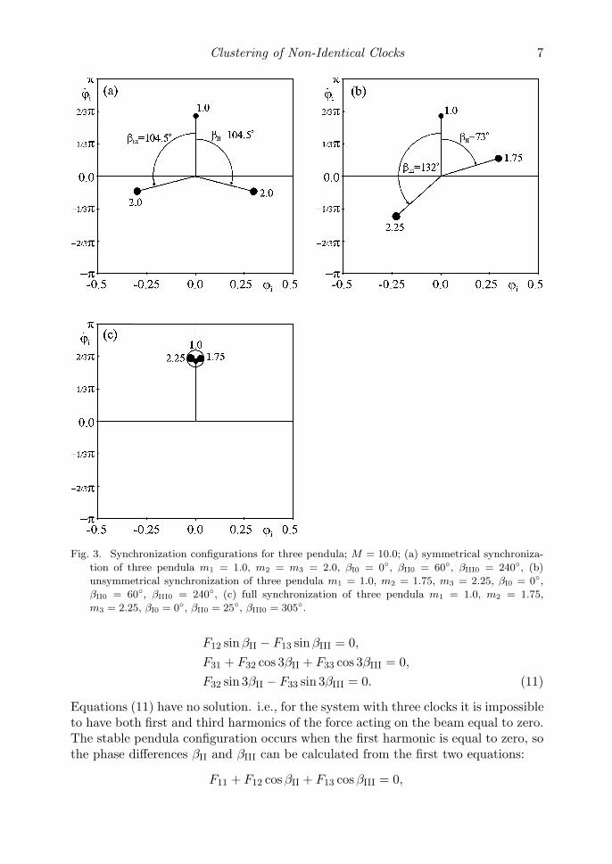
Fig. 3. Synchronization configurations for three pendula; M = 10.0; (a) symmetrical synchroniza-
tion of three pendula m1 = 1.0, m2 = m3 = 2.0, βI0 = 0◦, βII0 = 60◦, βIII0 = 240◦, (b)
unsymmetrical synchronization of three pendula m1 = 1.0, m2 = 1.75, m3 = 2.25, βI0 = 0◦,βII0 = 60◦, βIII0 = 240◦, (c) full synchronization of three pendula m1 = 1.0, m2 = 1.75,
m3 = 2.25, βI0 = 0◦, βII0 = 25◦, βIII0 = 305◦.
F12 sin βII − F13 sin βIII = 0,
F31 + F32 cos 3βII + F33 cos 3βIII = 0,
F32 sin 3βII − F33 sin 3βIII = 0. (11)
Equations (11) have no solution. i.e., for the system with three clocks it is impossibleto have both first and third harmonics of the force acting on the beam equal to zero.The stable pendula configuration occurs when the first harmonic is equal to zero, sothe phase differences βII and βIII can be calculated from the first two equations:
F11 + F12 cos βII + F13 cos βIII = 0,
8 K. Czo�lczynski, P. Perlikowski, A. Stefanki and T. Kapitaniak
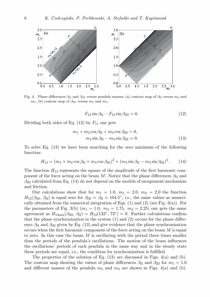
Fig. 4. Phase differences βII and βIII versus pendula masses; (a) contour map of βII versus m2 and
m3, (b) contour map of βIII versus m2 and m3.
F12 sin βII − F13 sin βIII = 0. (12)
Dividing both sides of Eq. (12) by F11 one gets
m1 + m2 cos βII + m3 cos βIII = 0,
m2 sin βII − m3 sin βIII = 0. (13)
To solve Eq. (13) we have been searching for the zero minimum of the followingfunction:
H13 = (m1 + m2 cos βII + m3 cos βIII)2 + (m2 sin βII − m3 sin βIII)
2 . (14)
The function H13 represents the square of the amplitude of the first harmonic com-ponent of the force acting on the beam M . Notice that the phase differences βII andβIII calculated from Eq. (14) do not depend on the models of escapement mechanismand friction.
Our calculations show that for m1 = 1.0, m2 = 2.0, m3 = 2.0 the functionH13(βIII, βII) is equal zero for βIII = βII = 104.5◦, i.e., the same values as numeri-cally obtained from the numerical integration of Eqs. (1) and (2) (see Fig. 3(a)). Forthe parameters of Fig. 3(b) (m1 = 1.0, m2 = 1.75, m3 = 2.25) one gets the sameagreement as H13min(βIII, βII) = H13(132◦, 73◦) = 0. Further calculations confirmthat the phase synchronization in the system (1) and (2) occurs for the phase differ-ence βII and βIII given by Eq. (13) and give evidence that the phase synchronizationoccurs when the first harmonic component of the force acting on the beam M is equalto zero. In this case the beam M is oscillating with the period three times smallerthan the periods of the pendula’s oscillations. The motion of the beam influencesthe oscillations’ periods of each pendula in the same way and in the steady statethese periods are equal, i.e., the condition for synchronization is fulfilled.
The properties of the solution of Eq. (13) are discussed in Figs. 4(a) and (b).The contour map showing the values of phase differences βII and βIII for m1 = 1.0and different masses of the pendula m2 and m3 are shown in Figs. 4(a) and (b).
Clustering of Non-Identical Clocks 9
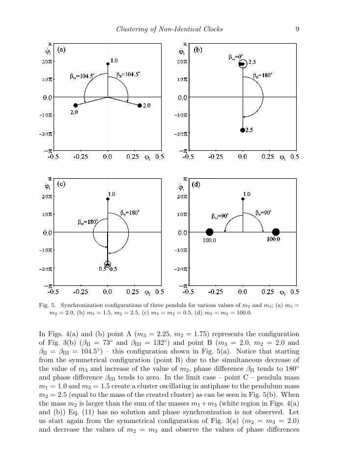
Fig. 5. Synchronization configurations of three pendula for various values of m2 and m3; (a) m3 =
m2 = 2.0, (b) m3 = 1.5, m2 = 2.5, (c) m3 = m2 = 0.5, (d) m3 = m2 = 100.0.
In Figs. 4(a) and (b) point A (m3 = 2.25, m2 = 1.75) represents the configurationof Fig. 3(b) (βII = 73◦ and βIII = 132◦) and point B (m3 = 2.0, m2 = 2.0 andβII = βIII = 104.5◦) – this configuration shown in Fig. 5(a). Notice that startingfrom the symmetrical configuration (point B) due to the simultaneous decrease ofthe value of m3 and increase of the value of m2, phase difference βII tends to 180◦and phase difference βIII tends to zero. In the limit case – point C – pendula massm1 = 1.0 and m3 = 1.5 create a cluster oscillating in antiphase to the pendulum massm2 = 2.5 (equal to the mass of the created cluster) as can be seen in Fig. 5(b). Whenthe mass m2 is larger than the sum of the masses m1 +m3 (white region in Figs. 4(a)and (b)) Eq. (11) has no solution and phase synchronization is not observed. Letus start again from the symmetrical configuration of Fig. 3(a) (m2 = m3 = 2.0)and decrease the values of m2 = m3 and observe the values of phase differences
10 K. Czo�lczynski, P. Perlikowski, A. Stefanki and T. Kapitaniak
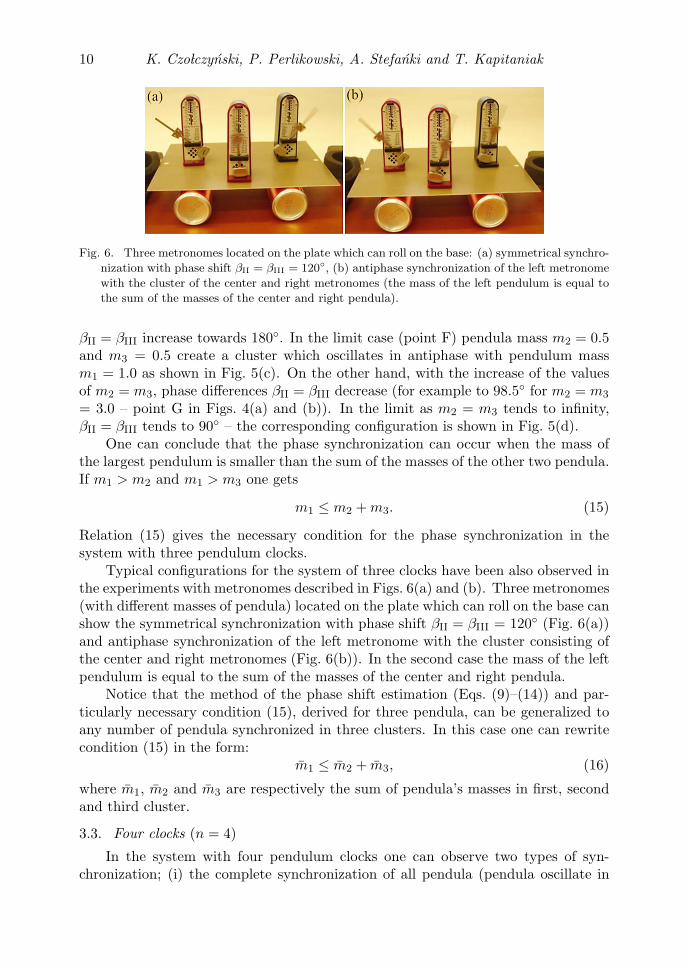
Fig. 6. Three metronomes located on the plate which can roll on the base: (a) symmetrical synchro-
nization with phase shift βII = βIII = 120◦, (b) antiphase synchronization of the left metronome
with the cluster of the center and right metronomes (the mass of the left pendulum is equal to
the sum of the masses of the center and right pendula).
βII = βIII increase towards 180◦. In the limit case (point F) pendula mass m2 = 0.5and m3 = 0.5 create a cluster which oscillates in antiphase with pendulum massm1 = 1.0 as shown in Fig. 5(c). On the other hand, with the increase of the valuesof m2 = m3, phase differences βII = βIII decrease (for example to 98.5◦ for m2 = m3
= 3.0 – point G in Figs. 4(a) and (b)). In the limit as m2 = m3 tends to infinity,βII = βIII tends to 90◦ – the corresponding configuration is shown in Fig. 5(d).
One can conclude that the phase synchronization can occur when the mass ofthe largest pendulum is smaller than the sum of the masses of the other two pendula.If m1 > m2 and m1 > m3 one gets
m1 ≤ m2 + m3. (15)
Relation (15) gives the necessary condition for the phase synchronization in thesystem with three pendulum clocks.
Typical configurations for the system of three clocks have been also observed inthe experiments with metronomes described in Figs. 6(a) and (b). Three metronomes(with different masses of pendula) located on the plate which can roll on the base canshow the symmetrical synchronization with phase shift βII = βIII = 120◦ (Fig. 6(a))and antiphase synchronization of the left metronome with the cluster consisting ofthe center and right metronomes (Fig. 6(b)). In the second case the mass of the leftpendulum is equal to the sum of the masses of the center and right pendula.
Notice that the method of the phase shift estimation (Eqs. (9)–(14)) and par-ticularly necessary condition (15), derived for three pendula, can be generalized toany number of pendula synchronized in three clusters. In this case one can rewritecondition (15) in the form:
m1 ≤ m2 + m3, (16)
where m1, m2 and m3 are respectively the sum of pendula’s masses in first, secondand third cluster.
3.3. Four clocks (n = 4)
In the system with four pendulum clocks one can observe two types of syn-chronization; (i) the complete synchronization of all pendula (pendula oscillate in
Clustering of Non-Identical Clocks 11
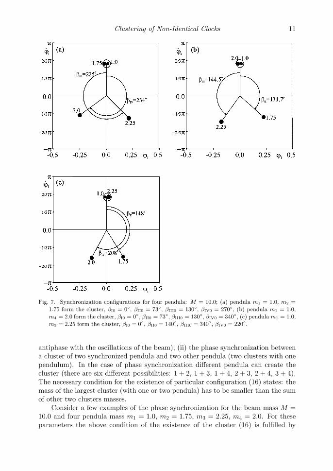
Fig. 7. Synchronization configurations for four pendula: M = 10.0; (a) pendula m1 = 1.0, m2 =
1.75 form the cluster, βI0 = 0◦, βII0 = 73◦, βIII0 = 130◦, βIV0 = 270◦, (b) pendula m1 = 1.0,
m4 = 2.0 form the cluster, βI0 = 0◦, βII0 = 73◦, βIII0 = 130◦, βIV0 = 340◦, (c) pendula m1 = 1.0,
m3 = 2.25 form the cluster, βI0 = 0◦, βII0 = 140◦, βIII0 = 340◦, βIV0 = 220◦.
antiphase with the oscillations of the beam), (ii) the phase synchronization betweena cluster of two synchronized pendula and two other pendula (two clusters with onependulum). In the case of phase synchronization different pendula can create thecluster (there are six different possibilities: 1 + 2, 1 + 3, 1 + 4, 2 + 3, 2 + 4, 3 + 4).The necessary condition for the existence of particular configuration (16) states: themass of the largest cluster (with one or two pendula) has to be smaller than the sumof other two clusters masses.
Consider a few examples of the phase synchronization for the beam mass M =10.0 and four pendula mass m1 = 1.0, m2 = 1.75, m3 = 2.25, m4 = 2.0. For theseparameters the above condition of the existence of the cluster (16) is fulfilled by
12 K. Czo�lczynski, P. Perlikowski, A. Stefanki and T. Kapitaniak
three pairs of pendula: 1 + 2, 1 + 3 and 1 + 4. The corresponding configurations areshown in Figs. 7(a)–(c). The same phase differences as observed in Figs. 7(a)–(c)can be calculated from the function H13 given by Eq. (14). Notice that in this casecluster has to be considered as a single pendulum with mass equal to the total massof the pendula in cluster.
3.4. Five clocks (n = 5)
In the system with five pendulum clocks we observed three different types of syn-chronization: (i) complete synchronization of all pendula, (ii) phase synchronizationof three clusters and (iii) phase synchronization of five pendula.
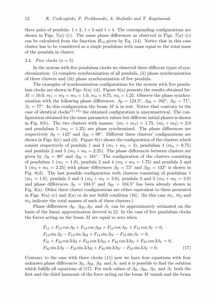
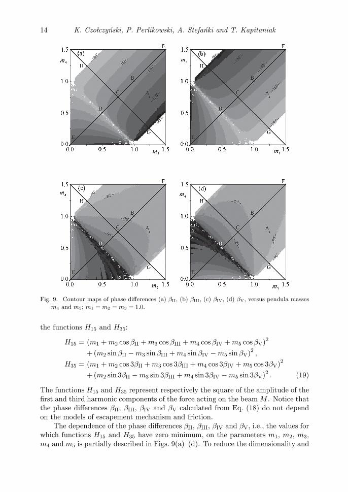
The examples of synchronization configurations for the system with five pendu-lum clocks are shown in Figs. 8(a)–(d). Figure 8(a) presents the results obtained for:M = 10.0, m1 = m2 = m3 = 1.0, m4 = 0.75, m5 = 1.25. Observe the phase synchro-nization with the following phase differences: βII = 124.5◦, βIII = 162◦, βIV = 71◦,βV = 77◦. In this configuration the beam M is in rest. Notice that contrary to thecase of identical clocks11),12) the obtained configuration is unsymmetrical. The con-figuration obtained for the same parameter values but different initial phases is shownin Fig. 8(b). The two clusters with masses: (m1 + m4) = 1.75, (m2 + m3) = 2.0and pendulum 5 (m5 = 1.25) are phase synchronized. The phase differences arerespectively βII = 142◦ and βIII = 98◦. Different three clusters’ configurations areshown in Figs. 6(c) and (d). Figure 8(c) shows the configuration of the clusters whichconsist respectively of pendula 1 and 3 (m1 + m3 = 3), pendulum 4 (m4 = 0.75)and pendula 2 and 5 (m2 + m5 = 2.25). The phase differences between clusters aregiven by βII = 80◦ and βIII = 161◦. The configuration of the clusters consistingof pendulum 1 (m1 = 1.0), pendula 2 and 4 (m2 + m4 = 1.75) and pendula 3 and5 (m3 + m5 = 2.25) with phase differences βII = 72◦ and βIII = 133◦ is shown inFig. 8(d). The last possible configuration with clusters consisting of pendulum 1(m1 = 1.0), pendula 2 and 4 (m2 + m4 = 2.0), pendula 3 and 5 (m3 + m5 = 2.0)and phase differences βII = 104.5◦ and βIII = 104.5◦ has been already shown inFig. 3(a). Other three cluster configurations are either equivalent to these presentedin Figs. 8(a)–(c) and 3(a) or do not fulfill condition (16). (In this case m1, m2 andm3 indicate the total masses of each of three clusters.)
Phase differences βII, βIII, βIV and βV can be approximately estimated on thebasis of the linear approximation derived in §2. In the case of five pendulum clocksthe forces acting on the beam M are equal to zero when
F11 + F12 cos βII + F13 cos βIII + F14 cos βIV + F15 cos βV = 0,
F12 sin βII − F13 sin βIII + F14 sin βIV − F15 sin βV = 0,
F31 + F32 cos 3βII + F33 cos 3βIII + F34 cos 3βIV + F35 cos 3βV = 0,
F32 sin 3βII − F33 sin 3βIII + F34 sin 3βIV − F35 sin 3βV = 0. (17)
Contrary to the case with three clocks (11) now we have four equations with fourunknown phase differences βII, βIII, βIV and βV and it is possible to find the solutionwhich fulfills all equations of (17). For such values of βII, βIII, βIV and βV both thefirst and the third harmonic of the force acting on the beam M vanish and the beam
Clustering of Non-Identical Clocks 13
Fig. 8. Synchronization configurations of five pendula: M = 10.0; m1 = m2 = m3 = 1.0, m4 =
0.75, m5 = 1.25; (a) configuration of five clusters, (b) configuration of three clusters mass
1.75, 2.0, 1.25, (c) configuration of three clusters of the following masses 2.0, 0.75, 2.25, (d)
configuration of three clusters of the following masses 1.0, 1.75, 2.25.
is in rest. Dividing the first two of Eq. (17) by F11 and the other two by F31 onegets
m1 + m2 cos βII + m3 cos βIII + m4 cos βIV + m5 cos βV = 0,
m2 sin βII − m3 sin βIII + m4 sin βIV − m5 sin βV = 0,
m1 + m2 cos 3βII + m3 cos 3βIII + m4 cos 3βIV + m5 cos 3βV = 0,
m2 sin 3βII − m3 sin 3βIII + m4 sin 3βIV − m5 sin 3βV = 0. (18)
Equation (18) has been solved by the method of searching for the zero minimum of
14 K. Czo�lczynski, P. Perlikowski, A. Stefanki and T. Kapitaniak
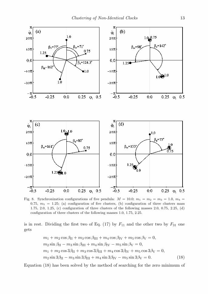
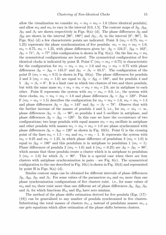
Fig. 9. Contour maps of phase differences (a) βII, (b) βIII, (c) βIV, (d) βV, versus pendula masses
m4 and m5; m1 = m2 = m3 = 1.0.
the functions H15 and H35:
H15 = (m1 + m2 cos βII + m3 cos βIII + m4 cos βIV + m5 cos βV)2
+ (m2 sin βII − m3 sin βIII + m4 sin βIV − m5 sin βV)2 ,
H35 = (m1 + m2 cos 3βII + m3 cos 3βIII + m4 cos 3βIV + m5 cos 3βV)2
+ (m2 sin 3βII − m3 sin 3βIII + m4 sin 3βIV − m5 sin 3βV)2 . (19)
The functions H15 and H35 represent respectively the square of the amplitude of thefirst and third harmonic components of the force acting on the beam M . Notice thatthe phase differences βII, βIII, βIV and βV calculated from Eq. (18) do not dependon the models of escapement mechanism and friction.
The dependence of the phase differences βII, βIII, βIV and βV, i.e., the values forwhich functions H15 and H35 have zero minimum, on the parameters m1, m2, m3,m4 and m5 is partially described in Figs. 9(a)–(d). To reduce the dimensionality and
Clustering of Non-Identical Clocks 15
allow the visualization we consider m1 = m2 = m3 = 1.0 (three identical pendula),and allow m4 and m5 to vary in the interval [0.0, 1.5]. The contour maps of βII, βIII,βIV and βV are shown respectively in Figs. 9(a)–(d). The phase differences βII andβIII are shown in the interval [90◦, 180◦] and βIV, βV in the interval [0◦, 90◦]. InFigs. 9(a)–(d) a few characteristic points are indicated. Point A (m4 = 0.75, m5 =1.25) represents the phase synchronization of five pendula: m1 = m2 = m3 = 1.0,m4 = 0.75, m5 = 1.25, with phase differences given by: βII = 124.5◦, βIII = 162◦,βIV = 71◦, βV = 77◦ (this configuration is shown in Fig. 8(a)). On the line m4 = m5
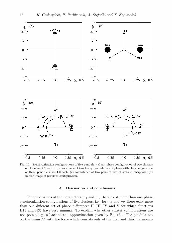
the symmetrical configurations are located. The symmetrical configuration of fiveidentical clocks is indicated by point B. Point C (m5 = m4 = 0.75) is characteristicfor the configuration for m1 = m2 = m3 = 1.0 and m4 = m5 = 0.75 with phasedifferences βII = βIII = 145.5◦ and βIV = βV = 65.5◦. The configuration of thepoint D (m5 = m4 = 0.5) is shown in Fig. 10(a). The phase differences for pendula2 and 3 (m2 = m3 = 1.0) are equal to βII = βIII = 180◦, and for pendula 4 and5 βIV = βV = 0◦. It is a limit case in which two clusters of two and three pendula,but with the same mass m1 + m4 + m5 = m2 + m3 = 2.0, are in antiphase to eachother. Point E represents the system with m5 = m4 = 0.0, i.e., the system withthree clocks, m1 = m2 = m3 = 1.0 and phase differences βII = βIII = 120◦. PointF (m5 = m4 = 1.5) describes the configuration for m2 = m3 = 1.0, m4 = m5 = 1.5and phase differences βII = βIII = 143◦ and βIV = βV = 78◦. Observe that withthe further increase of the masses of pendula 4 and 5, i.e., for m5 = m4 → ∞,phase differences βIV = βV → 90◦, so pendula 4 and 5 oscillate in antiphase, andphase differences βII = βIII → 120◦. In this case we have the co-existence of twoconfigurations; two large pendula with equal masses m5 = m4 oscillate in antiphaseand other pendula with masses m1 = m2 = m3 = 1.0 are phase synchronized withphase differences βII = βIII = 120◦ as shown in Fig. 10(b). Point G is the crossingpoint of the lines m4 = 1.5 − m5 and m4 = m5 − 1. It represents the system withm4 = 0.25 and m5 = 1.25, in which phase difference of pendulum 3 (m3 = 1.0) isequal to βIII = 180◦ and this pendulum is in antiphase to pendulum 1 (m1 = 1).Phase differences of pendula 2 (m2 = 1.0) and 4 (m4 = 0.25) are βII = βIV = 90◦,which means that these pendula create a cluster which is in antiphase to pendulum5 (m5 = 1.0) for which βV = 90◦. This is a special case when there are fourclusters with antiphase synchronization in pairs – see Fig. 8(c). The symmetricalconfiguration to the one described in Fig. 10(c) is shown in Fig. 10(d) and representedby point H in Figs. 9(a)–(d).
Similar contour maps can be obtained for different intervals of phase differencesβII, βIII, βIV and βV. For some values of the parameters m4 and m5 more than onephase synchronization configurations of five clusters exist. i.e., for some values ofm4 and m5 there exist more than one different set of phase differences βII, βIII, βIV
and βV for which functions H15 and H35 have zero minima.The method of the phase shifts estimation derived for five pendula (Eqs. (17)–
(19)) can be generalized to any number of pendula synchronized in five clusters.Substituting the total masses of clusters m1−5 instead of pendulum masses m1−5
one gets equations which allow estimation of the phase shifts between clusters.
16 K. Czo�lczynski, P. Perlikowski, A. Stefanki and T. Kapitaniak
Fig. 10. Synchronization configurations of five pendula; (a) antiphase configuration of two clusters
of the mass 2.0 each, (b) coexistence of two heavy pendula in antiphase with the configuration
of three pendula mass 1.0 each, (c) coexistence of two pairs of two clusters in antiphase; (d)
mirror image of previous configuration.
§4. Discussion and conclusions
For some values of the parameters m4 and m5 there exist more than one phasesynchronization configurations of five clusters, i.e., for m4 and m5 there exist morethan one different set of phase differences II, III, IV and V for which functionsH15 and H35 have zero minima. To explain why other cluster configurations arenot possible goes back to the approximation given by Eq. (6). The pendula acton the beam M with the force which consists only of the first and third harmonics
Clustering of Non-Identical Clocks 17
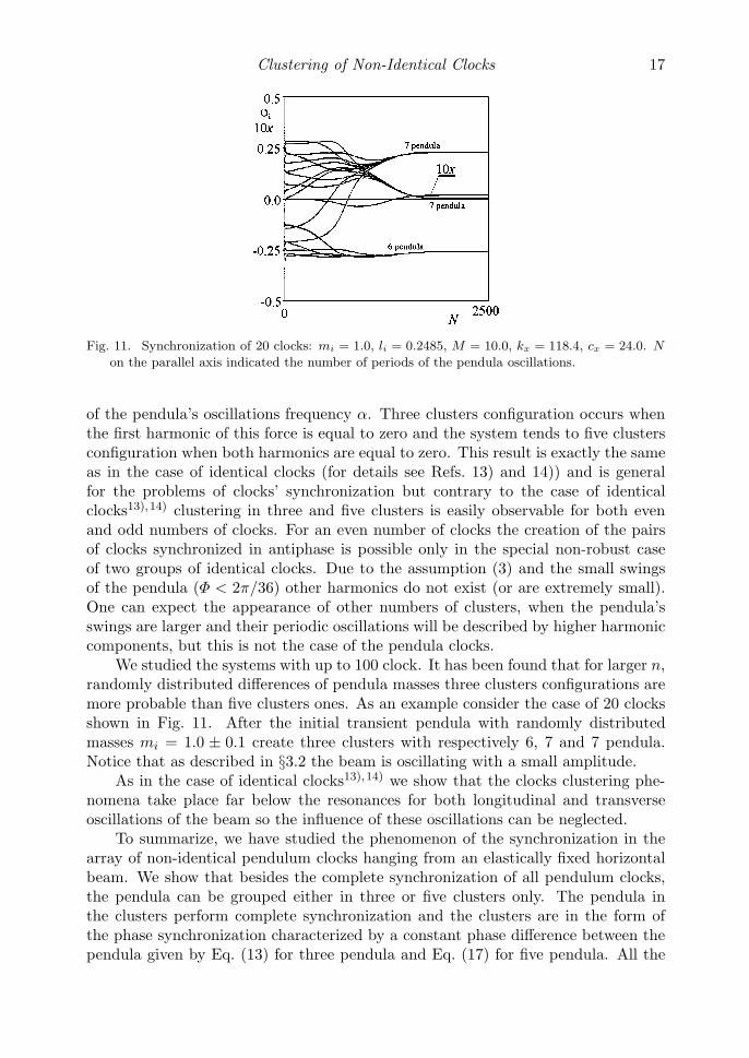
Fig. 11. Synchronization of 20 clocks: mi = 1.0, li = 0.2485, M = 10.0, kx = 118.4, cx = 24.0. N
on the parallel axis indicated the number of periods of the pendula oscillations.
of the pendula’s oscillations frequency α. Three clusters configuration occurs whenthe first harmonic of this force is equal to zero and the system tends to five clustersconfiguration when both harmonics are equal to zero. This result is exactly the sameas in the case of identical clocks (for details see Refs. 13) and 14)) and is generalfor the problems of clocks’ synchronization but contrary to the case of identicalclocks13),14) clustering in three and five clusters is easily observable for both evenand odd numbers of clocks. For an even number of clocks the creation of the pairsof clocks synchronized in antiphase is possible only in the special non-robust caseof two groups of identical clocks. Due to the assumption (3) and the small swingsof the pendula (Φ < 2π/36) other harmonics do not exist (or are extremely small).One can expect the appearance of other numbers of clusters, when the pendula’sswings are larger and their periodic oscillations will be described by higher harmoniccomponents, but this is not the case of the pendula clocks.
We studied the systems with up to 100 clock. It has been found that for larger n,randomly distributed differences of pendula masses three clusters configurations aremore probable than five clusters ones. As an example consider the case of 20 clocksshown in Fig. 11. After the initial transient pendula with randomly distributedmasses mi = 1.0 ± 0.1 create three clusters with respectively 6, 7 and 7 pendula.Notice that as described in §3.2 the beam is oscillating with a small amplitude.
As in the case of identical clocks13),14) we show that the clocks clustering phe-nomena take place far below the resonances for both longitudinal and transverseoscillations of the beam so the influence of these oscillations can be neglected.
To summarize, we have studied the phenomenon of the synchronization in thearray of non-identical pendulum clocks hanging from an elastically fixed horizontalbeam. We show that besides the complete synchronization of all pendulum clocks,the pendula can be grouped either in three or five clusters only. The pendula inthe clusters perform complete synchronization and the clusters are in the form ofthe phase synchronization characterized by a constant phase difference between thependula given by Eq. (13) for three pendula and Eq. (17) for five pendula. All the
18 K. Czo�lczynski, P. Perlikowski, A. Stefanki and T. Kapitaniak
pendula configurations reported in this paper are stable and robust as they existfor the given sets of system (1) and (2) parameters which have positive Lebesquemeasure.
Acknowledgements
This work has been supported by the Foundation for Polish Science, Team Pro-gram Project No TEAM/2010/5/5. P.P. acknowledges the support from Foundationfor Polish Science (the START fellowship).
References
1) C. Huygens, Horoloqium Oscilatorium (Apud F. Muquet, Parisiis, 1673), English transla-tion: The pendulum clock (Iowa State University Press, Ames, 1986).
2) C. Huygens, Letter to de Sluse, in Oeuveres Completes de Christian Huygens (letters;no. 1333 of 24 February 1665, no. 1335 of 26 February 1665, no. 1345 of 6 March 1665),(Societe Hollandaise Des Sciences, Martinus Nijhoff, La Haye, 1893).
3) A. Pikovsky, M. Resenblum and J. Kurths, Synchronization: An Universal Concept inNonlinear Sciences (Cambridge University Press, Cambridge, 2001).
4) I. I. Blekham, Synchronization in Science and Technology (ASME, New York, 1988).5) A. Yu. Pogromsky, V. N. Belykh and H. Nijmeijer, “Controlled synchronization of pen-
dula”, in Proceedings of the 42nd IEEE Conference on Design and Control, 2003, Maui,Hawaii (IEEE, 2003), pp. 4381–4385.
6) M. Bennet, M. F. Schatz, H. Rockwood and K. Wiesenfeld, Proc. R. Soc. London A 458(2002), 563.
7) M. Senator, J. Sound and Vibration 291 (2006), 566.8) R. Dilao, Chaos 19 (2009), 023118.9) M. Kumon, R. Washizaki, J. Sato, R. K. I. Mizumoto and Z. Iwai, “Controlled synchroniza-
tion of two 1-DOF coupled oscillators” in Proceedings of the 15th IFAC World Congress,Barcelona, 2002 (Pergamon, 2003).
10) A. L. Fradkov and B. Andrievsky, Int. J. Non-linear Mech. 42 (2007), 895.11) J. Pantaleone, Am. J. Phys. 70 (2002), 992.12) H. Ulrichs, A. Mann and U. Parlitz, Chaos 19 (2009), 043120.13) K. Czolczynski, P. Perlikowski, A. Stefanski and T. Kapitaniak, Physica A 388 (2009),
5013.14) K. Czolczynski, P. Perlikowski, A. Stefanski and T. Kapitaniak, Prog. Theor. Phys. 122
(2009), 1027.15) A. L. Rowlings, The Science of Clocks and Watches (Pitman, New York 1944).16) A. Andronov, A. Witt and S. Khaikin, Theory of Oscillations (Pergamon, Oxford, 1966).17) F. C. Moon and P. D. Stiefel, Philos. Trans. R. Soc. A 364 (2006), 2539.18) A. V. Roup, D. S. Bernstein, S. G. Nersesov, W. S. Haddad and V. Chellaboina, Int. J.
Control 76 (2003), 1685.19) A. M. Lepschy, G. A. Mian and U. Viaro, IEEE Trans. Education 35 (1993), 3.20) K. Czolczynski, P. Perlikowski, A. Stefanski and T. Kapitaniak, Int. J. Bif. Chaos (2011),
in press.