Embed Size (px)
Citation preview

Code of Practice for Access and
Working Scaffolds
H
S AHEALTH AND SAFETY
AUTHORITY
&
National Authority for Occupational Safety and Health

BAILE ÁTHA CLIATH:ARNA FHOILSIÚ AG OIFIG AN tSOLÁTHAIR.
Le ceannach díreach ónOIFIG DHÍOLTA FOILSEACHÁN RIALTAIS, TEACH SUN ALLIANCE,
SRÁID THEACH LAIGHEAN, BAILE ÁTHA CLIATH 2,nó tríd an bpost ó
FOILSEACHÁIN RIALTAIS, AN RANNÓG POST-TRÁCHTA,4-5 BÓTHAR FHEARCHAIR, BAILE ÁTHA CLIATH 2,(Teil: 01-6613111 - fo-líne. 4040/4045; Fax: 01-4752760)
nó trí aon díoltóir leabhar.
DUBLIN:PUBLISHED BY THE STATIONERY OFFICE.
To be purchased directly from theGOVERNMENT PUBLICATIONS SALE OFFICE, SUN ALLIANCE HOUSE,
MOLESWORTH STREET, DUBLIN 2,or by mail order from
GOVERNMENT PUBLICATIONS, POSTAL TRADE SECTION,4-5 HARCOURT ROAD, DUBLIN 2,
(Tel: 01-6613111 - ext. 4040/4045; Fax: 01-4752760)or through any bookseller.
ALSO FROM THE HEALTH AND SAFETY AUTHORITY,10 HOGAN PLACE, DUBLIN 2
Price: IR£5.00€6.35
P. 63547 Gr.30–01 5/99 5,000 Brunswick Press Ltd.
ForewordThe National Authority for Occupational Safety and Health (by virtue of Section 30 of theSafety, Health and Welfare Act, 1989, following consultation with the statutory Health andSafety Authority Advisory Committee on Construction Safety and with the consent of Mr TomKitt, TD, Minister of State at the Department of Enterprise, Trade and Employment, given on11th December, 1998) has issued a Code of Practice entitled “Code of Practice for Access andWorking Scaffolds”.
The Code of Practice provides practical guidance for persons who have specific duties inrelation to the supply, design, construction and use of scaffolds, including suppliers, designersof scaffold structures, project supervisors for the design and construction stages, contractors andworkers, in relation to the observance of their duties under Sections 6 to 12 of the Safety, Healthand Welfare at Work Act, 1989 (No. 7 of 1989), Parts II, III, IV and XIII of the Safety, Healthand Welfare at Work (Construction) Regulations, 1995 (S.I. No. 138 of 1995) and Parts II, IV, Vand VIII of the Safety, Health and Welfare at Work (General Application) Regulations, 1993(S.I. No. 44 of 1993).
The Code of Practice comes into effect on June 1st, 1999.
Notice of the issue of this Code of Practice was published in the “Iris Oifigiuil” of June 18th,1999.
CD BodySecretary to the Board
iii
Code of Practice for Access and Working Scaffolds

AcknowledgementsThe text of this code of practice was drafted by an ad-hoc group reporting to the Advisory Committee onConstruction Safety and was then subsequently accepted by the Advisory Committee on Construction Safetyand approved by the Board of the Health and Safety Authority.
Members of the Ad-Hoc GroupName OrganisationMr. Robert Roe (Chairman) H.S.A.Mr. Robert Byrne FÁSMr. Joe Fanning Alloy Access Ltd. - C.I.F.Mr. Paul Hansard U.C.A.T.Mr. Leo Harmon Ascon Ltd. - C.I.F.Mr. Vincent McGauran H.S.A.Mr. Kevin Sheridan FÁSMr. Fergus Whelan I.C.T.U.Mr. John McCabe Chadwicks - C.I.F.Mr. Tommy O’Sullivan (Secretary) H.S.A.
Members of the Advisory Committee on Construction SafetyName OrganisationMr. Sylvester Cronin (Chairman) H.S.A. Board MemberMr. Robert Byrne FASMr. John Graby R.I.A.I.Mr. Niall Irwin O.P.A.T.S.I. - I.C.T.U.Mr. Jack Kavanagh Kavanagh Mansfield & Prtnrs.- I.E.I./A.C.E.I.Mr. Peter McCabe C.I.F.Mr. Jim McCafferty A.I.B. - I.B.E.C.Mr. Vincent McGauran H.S.A.Mr. Gerard O’Sullivan McBains Cooper International - S.C.S.Mr. John Ryan P.J. Walls Ltd - C.I.F.Mr. Robert Roe H.S.A.Mr. Fergus Whelan I.C.T.U.Mr. Con Body (Secretary) H.S.A. Ms. Marie Manning (Secretary) H.S.A.Mr. Philipp Rahn (Secretary) H.S.A.
iv
National Authority for Occupational Safety and Health
British Standards InstitutionExtracts from BS 5973 : 1993 are reproduced with the permission of BSI under licence number PD\ 19990198. Complete copies of the standard can be obtained by post from BSI Customer Services, 389 ChiswickHigh Road, London W4 4AL.
FOREWORD iii
ACKNOWLEDGEMENTS iv
1. INTRODUCTION 1
1.1. Background 1
1.2. Status of Code of Practice 1
1.3. Scope of Code of Practice 1
1.4. Scaffolding in Construction 1
1.5. Types of Scaffold 2
1.6. Scaffolding Hazards 2
1.7. Risk Assessment 2
1.8. Statutory Duties 21.8.1. Project Supervisor for the
Design Stage 21.8.2. Designers 21.8.3. Project Supervisor for the
Construction Stage 21.8.4. Contractors 31.8.5. Workers 3
1.9. Illustrations 3
1.10. Definitions 31.10.1. Types and Dimensions of
Scaffolds 31.10.2. Structural Members 41.10.3. Scaffold Fittings 41.10.4. Other Terms in General Use 5
2. MANAGEMENT AND CONTROL OF SCAFFOLDING 7
2.1. Management of Scaffolding Activities 7
2.2. Choice of Scaffolding Equipment 8
2.3. Layout and Design 82.3.1. Layout 82.3.2. Structural Design of Scaffolds 92.3.3. Building Design and Scaffold
Erection 9
2.4. Erection Scheduling 10
2.5. Planning for Use and Maintenance 10
2.6. Information to Purchasers of Scaffolding Equipment 10
2.7. Information to Users of Scaffolding Components 10
3. ERECTION OF SCAFFOLDS 12
3.1. Safe Erection and Dismantling 123.1.1. Safety of Scaffolders 123.1.2. Safety of Other Workers and
Persons 123.1.3. Incomplete Scaffolding 13
3.2. Materials 133.2.1. Inspection Prior to Use 133.2.2. Standards 133.2.3. Transoms 133.2.4. Ledgers 133.2.5. Couplers 13
3.3. Stability 133.3.1. Foundations 143.3.2. Ties 153.3.3. Tie Spacing 183.3.4. Bracing 19
3.4. Working Platforms 213.4.1. Decking 213.4.2. Toe-Boards 223.4.3. Maximum Gap Between
Building and Platform 223.4.4. Cantilever Platform (Stage)
Brackets 22
3.5. Guard-Rails 22
3.6. Falling Object Protection 223.6.1. Brick Guards 223.6.2. Sheeting 233.6.3. Fans 23
3.7. Access to the Scaffold 233.7.1. Ladder Access 23
v
Code of Practice for Access and Working Scaffolds
Table of Contents
3.8. Loading of the Scaffold 243.8.1. Loading Bays 243.8.2. Signs 253.8.3. Loading Charts 26
3.9. Free-Standing and Mobile Access Towers 263.9.1. Types of Tower 263.9.2. Manufacturer’s Instructions 273.9.3. Stability 273.9.4. Ground Surface 273.9.5. Bracing 273.9.6. Castors 283.9.7. Working Platform 273.9.8. Tower Access 273.9.9. Overhead Electricity Lines 273.9.10. Instruction, Training and
Supervision 273.9.11. Tower Use 28
3.10. Scaffolds and Electricity 283.10.1. Overhead Electricity Lines 283.10.2. Portable Electrical Equipment 283.10.3. Lightning 28
3.11. Erection on Public Streets 293.11.1. Through Access 293.11.2. Adjacent Parking or Traffic 29
4. INSPECTION AND HAND-OVER 30
5. USE, MODIFICATION AND MAINTENANCE 31
5.1. Scaffold Users 315.2. Modification 315.3. Maintenance 315.4. Inspection Before and During Use 31
6. DISMANTLING 32
6.1. Stability 326.2. Protection from Falls 326.3 Protection from Falling Objects 32
7. COMPETENCE 33
7.1. Competence of Scaffolders 337.1.1. Training 337.1.2. Experience 337.1.3. Assessment, Certification and
Registration 33
7.2. Competence for Inspection 337.2.1. Training for Inspection 33
7.3. Training and Instruction for Scaffold Users 337.3.1. Contents of Induction 34
7.4. Training and Instruction of Equipment Operators 34
APPENDIX A: TUBE AND FITTING SCAFFOLDS 35
APPENDIX B: EXAMPLE CHECK-LISTS 38
APPENDIX C: FORM CR8 REPORT OF RESULTS OFINSPECTION OF: SCAFFOLD 42
APPENDIX D: WEIGHTS OF TYPICALBUILDING MATERIALS 45
APPENDIX E: INFORMATION SOURCES 48
INDEX 51
vi
National Authority for Occupational Safety and Health
1.1. BackgroundThis code of practice is the result of a jointinitiative, which involved the Health and SafetyAuthority, the Construction Industry Federation andthe Irish Congress of Trade Unions, to improve thestandard of scaffolding. The code was drafted inconsultation with the organisations that wererepresented on the Advisory Committee onConstruction Safety. (See acknowledgements)
1.2. Status of Code of PracticeThis code of practice is issued by the NationalAuthority for Occupational Safety and Health underSection 30 of the Safety Health and Welfare atWork Act, 1989 and with the consent of theMinister for Labour, Trade and Consumer Affairs.The code is intended to provide practical guidanceto scaffold erectors, contractors and users ofscaffolding on the requirements and prohibitions setout in the relevant statutory instruments.
In particular, but not exclusively, the code providesguidance in relation to Part XIII of the SafetyHealth and Welfare at Work (Construction)Regulations, 1995, Working at Heights.
A failure to observe any part of this code will not ofitself render a person liable to civil or criminalproceedings. Where the code of practice givespractical guidance on the observance of any of therelevant statutory provisions then compliance ornon-compliance with those provisions of the codemay be admissible in evidence in any criminalproceedings.
1.3. Scope of Code of PracticeThis code applies to all places of work wherescaffolds are used to provide working platforms,protection from falls or means of access duringconstruction work.
The code of practice gives recommendations andpractical guidance on the erection, use, inspectionand dismantling of simple access and workingscaffolds. It also gives recommendations andpractical guidance on the training and instruction ofthose erecting, dismantling and using scaffolds.
The code deals mainly with system scaffolds asthese are the most common scaffolds used inIreland. It also contains outline guidance on theerection of basic tube and fitting scaffolds. Thecode does not give detailed recommendations orguidance on special scaffolds such as cantilever,truss-out or slung scaffolds.
BS 5973 Code of Practice for Access and WorkingScaffolds in Steel gives comprehensiverecommendations and guidance on the design,erection, use and dismantling of tube and fittingscaffolds and special scaffolds.
1.4. Scaffolding in ConstructionScaffolding performs several important functionsduring the construction process. It provides atemporary working platform to enable work to beperformed at a height. It is also used to protectpersons working at a height from falling or toprotect persons working below from falling objects.
Falling from a height is the most common cause ofaccidental death and serious injury in theconstruction industry. Scaffolding which isadequately erected and maintained can preventmany such accidents.
1.5. Types of ScaffoldThere are currently two main types of scaffolding inuse in Ireland: system scaffolds and tube and fittingscaffolds
System scaffolding has become the most commontype of scaffolding in use due to its ease of erection,use and reduced labour requirements. A systemscaffold is a scaffold made of prefabricatedelements and designed and manufactured inaccordance with IS/HD 1000 or an equivalentstandard. Each type of system scaffolding consistsof a range of components such as standards,ledgers, transoms and base plates and has its ownspecific erection requirements.
Tube and fitting scaffolding is constructed fromsteel tubing and several types of couplers. Properlyconstructed, it forms a robust structure since theledgers and standards are usually continuous acrossseveral bays or lifts.
1
Code of Practice for Access and Working Scaffolds
1. Introduction
1.6. Scaffolding Hazards Poorly erected or maintained scaffolds can fail,sometimes catastrophically. Where a scaffold hasinadequate foundations, tying or bracing or isoverloaded, it can collapse, endangering workers andthe public. Where scaffold boards or guard-rails aremissing, workers can suffer severe injuries due tofalls. Scaffolders will be at risk where a safe systemof work is not in place to protect them from falls.
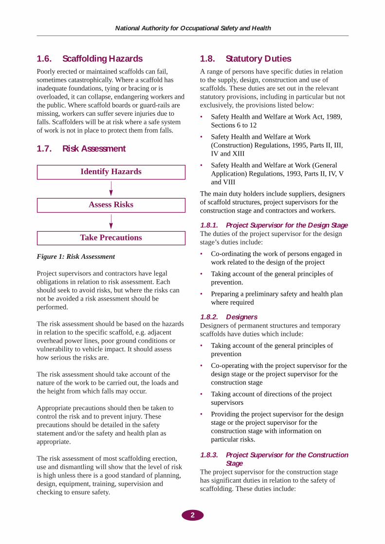
1.7. Risk Assessment
Figure 1: Risk Assessment
Project supervisors and contractors have legalobligations in relation to risk assessment. Eachshould seek to avoid risks, but where the risks cannot be avoided a risk assessment should beperformed.
The risk assessment should be based on the hazardsin relation to the specific scaffold, e.g. adjacentoverhead power lines, poor ground conditions orvulnerability to vehicle impact. It should assesshow serious the risks are.
The risk assessment should take account of thenature of the work to be carried out, the loads andthe height from which falls may occur.
Appropriate precautions should then be taken tocontrol the risk and to prevent injury. Theseprecautions should be detailed in the safetystatement and/or the safety and health plan asappropriate.
The risk assessment of most scaffolding erection,use and dismantling will show that the level of riskis high unless there is a good standard of planning,design, equipment, training, supervision andchecking to ensure safety.
1.8. Statutory DutiesA range of persons have specific duties in relationto the supply, design, construction and use ofscaffolds. These duties are set out in the relevantstatutory provisions, including in particular but notexclusively, the provisions listed below:
• Safety Health and Welfare at Work Act, 1989,Sections 6 to 12
• Safety Health and Welfare at Work(Construction) Regulations, 1995, Parts II, III,IV and XIII
• Safety Health and Welfare at Work (GeneralApplication) Regulations, 1993, Parts II, IV, Vand VIII
The main duty holders include suppliers, designersof scaffold structures, project supervisors for theconstruction stage and contractors and workers.
1.8.1. Project Supervisor for the Design StageThe duties of the project supervisor for the designstage’s duties include:
• Co-ordinating the work of persons engaged inwork related to the design of the project
• Taking account of the general principles ofprevention.
• Preparing a preliminary safety and health planwhere required
1.8.2. DesignersDesigners of permanent structures and temporaryscaffolds have duties which include:
• Taking account of the general principles ofprevention
• Co-operating with the project supervisor for thedesign stage or the project supervisor for theconstruction stage
• Taking account of directions of the projectsupervisors
• Providing the project supervisor for the designstage or the project supervisor for theconstruction stage with information onparticular risks.
1.8.3. Project Supervisor for the ConstructionStage
The project supervisor for the construction stagehas significant duties in relation to the safety ofscaffolding. These duties include:
2
National Authority for Occupational Safety and Health
Identify Hazards
Assess Risks
Take Precautions
• Developing the preliminary safety and healthplan
• Co-ordination of the implementation of theregulations
• The organising of co-operation betweencontractors and the co-ordination of theiractivities
• The co-ordination of arrangements for thechecking of safe working procedures.
For example, the project supervisor for theconstruction stage should ensure that arrangementsare in place to communicate the requirements of thescaffold users to the scaffold erectors.
1.8.4. ContractorsContractors, including sub-contractors andspecialist scaffolding contractors, have a verysignificant range of responsibilities under therelevant statutory provisions. These duties includethe following:
• Every contractor using a scaffold should satisfyhimself, before using the scaffold, that it isstable, that the materials are sound and that thesafeguards required by the regulations are inplace.
• A contractor may not use a scaffold unless ithas been inspected before use and within theprevious seven days and form CR 8 report ofresult of inspection of scaffolds has beencompleted.
Where a scaffolding contractor is engaged byanother contractor to construct, maintain ordismantle a scaffold each contractor will assume anumber of duties under the regulations. Theagreement between contractors should clearly statewhich contractor is responsible for fulfillingspecific duties. For example, the agreement shouldbe clear as to which contractor is responsible forperforming inspections of the scaffold.
1.8.5. WorkersWorkers, including scaffold erectors, haveresponsibilities under the relevant statutoryprovisions which include:
• Taking care for their own safety and the safetyof others
• Co-operating with their employer and takingaccount of training and instruction given by theemployer
• Making full use of harnesses, helmets or otherprotective equipment provided.
• Reporting to his employer defects in thescaffold or in the system of work which mayendanger health and safety
• Not interfering with or misusing the scaffold.
For example, scaffold erectors should ensure that,at the time of handing over of the scaffold to thecontractor, the scaffold is fit for its intendedpurpose and it is in a safe and stable condition.
1.9. IllustrationsThe illustrations used in this code show a type ofsystem scaffold which is in common use in Ireland.The illustrations are intended to apply to simpleaccess and working scaffolds in general. They donot supersede or replace the illustrations orarrangements contained in the systemmanufacturer’s erection instructions. Suchinstructions should always be referred to.
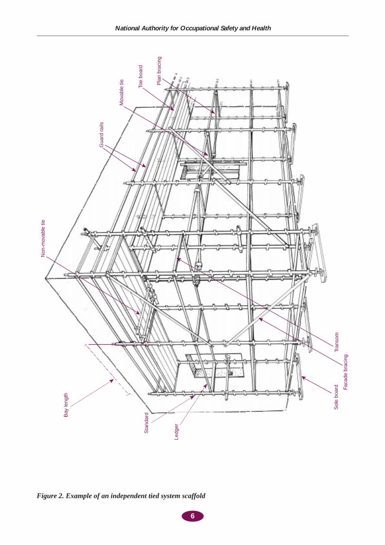
1.10. DefinitionsFor the purposes of this Code of Practice, thefollowing definitions apply (see figure 2 on page 6):
1.10.1. Types and Dimensions of Scaffolds Base Lift: A lift erected near the groundBay: The space between the centre lines of twoadjacent standards along the face of a scaffoldBay Length: The distance between the centres oftwo adjacent standards, measured horizontallyalong the face of a scaffoldHeight: The height measured from the foundationto the top assembly of ledgers and transoms (cf. LiftHeight)Length: The length of a scaffold between itsextreme standards, sometimes designated by thenumber of bays (cf. Bay Length)Lift: The assembly of ledgers and transomsforming each horizontal level of a scaffoldLift Height: The vertical distance between twolifts, measured centre to centre Scaffold: A temporarily provided structure whichprovides access, on or from which persons work orwhich is used to support materials, plant orequipmentFree Standing Scaffold: A scaffold which is notattached to any other structure and is stable againstoverturning on its own account or, if necessary,assisted by guys or rakers and anchors
3
Code of Practice for Access and Working Scaffolds
Independent Tied Scaffold: A scaffold, which hastwo lines of standards, one line supporting theoutside of the deck and one the inside. (see figure 2on page 6). It is not free-standing being connectedto the building.Slung Scaffold: A scaffold hanging on tubes, ropesor chains from a structure overhead. It is notcapable of being moved or loweredSuspended Scaffold: A scaffold hanging on ropeswhich is capable of being suspended or raised orloweredSystem Scaffold: a service and working scaffoldmade of prefabricated elements and designed andmanufactured in accordance with IS/HD 1000 or anequivalent standard.Width: The width of a scaffold measured at rightangles to the ledgers from centre to centre of theuprights
1.10.2. Structural MembersBrace: A tube placed diagonally with respect to thevertical or horizontal members of a scaffold andfixed onto them to afford stabilityCross Brace: See Ledger BraceFacade Brace: A brace parallel to the face of abuildingKnee Brace: A brace across the corner of anopening in a scaffold to stiffen the angles or tostiffen the end support of a beamLedger Brace: A brace at right angles to thebuilding in a vertical planePlan Brace: A brace in a horizontal planeTransverse Brace: A brace generally in the planeof the shorter dimension of the scaffoldBridle: A tube fixed across an opening or parallelto the face of a building to support the inner end ofa transom or tie tubeButting Tube: A tube, which butts up against thefacade of a building or other surface to prevent thescaffold, moving towards that surfaceGuard-Rail: A member incorporated in a scaffoldto prevent the fall of a person from a platform oraccess wayEnd Guard-Rail: A guard-rail placed across theend of a scaffold or used to isolate an unboardedpart Ledger: A longitudinal tube normally fixed parallelto the face of a building in the direction of thelarger dimensions of the scaffoldRaker: An inclined load-bearing tubeReveal Tube; A tube fixed by means of a threadedfitting or by wedging between two oppositesurfaces of a structure, e.g. between two window
reveals, to form an anchor to which the scaffoldmay be tiedStandard: A vertical or near vertical tubeTie or Tie Assembly: The components attached to an anchorage or the building or framed around a part of it or wedged or screwed into it with a tie tube. Used to secure the scaffold to the structureMovable Tie: A tie, which may be temporarilymoved for the execution of workNon-Movable Tie: A tie, which will not be movedduring the life of a scaffold, as agreed between theuser and the scaffold erectorReveal Tie: The assembly of a reveal tube withwedges or screwed fittings, and pads, if required,fixed between opposing faces of an opening in awall together with the tie tubeThrough Tie; A tie assembly through a window orother opening in a wallTransom: A tube spanning across ledgers to formthe support for boards or units forming the workingplatform or to connect the outer standards to theinner standardsButting Transom; A transom extended inwards tobutt the building to prevent the scaffolding movingtowards the buildingSway Transom; A transom extended inwards incontact with a reveal or the side of a column toprevent the scaffold moving sideways
1.10.3. Scaffold FittingsBase Plate: A metal plate with a spigot fordistributing the load from a standard or raker orother load-bearing tubeAdjustable Base Plate: A metal base plateembodying a screw-jackCoupler; A component used to fix scaffold tubestogetherCheck Coupler or Safety Coupler; A coupleradded to a joint under load to give security to thecoupler(s) carrying the loadRight Angle Coupler: A coupler used to join tubesat right anglesSleeve Coupler: An external coupler used to joinone tube to another coaxiallySupplementary Coupler: Coupler(s) added to ajoint to back up the main coupler taking the loadwhen the estimated load on the joint is in excess ofthe safe working load of the main couplerSwivel Coupler; A coupler for joining tubes at anangle other than a right angleCantilever Bracket or Stage Bracket: A bracketusually attached to the inside of a scaffold to enable
4
National Authority for Occupational Safety and Health
boards to be placed between the scaffold and thebuildingJoint Pin: An expanding fitting placed in the boreof a tube to connect one tube to another coaxially(see Spigot)Reveal Pin: A fitting used for tightening a revealtube between two opposing surfacesSole Board: A timber, concrete or metal spreaderused to distribute the load from a standard or baseplate to the groundSpigot: An internal fitting to join one tube toanother coaxially (see Joint Pin)Spigot Pin: A pin placed transversely through thespigot and the scaffold tube to prevent the two fromcoming apart
1.10.4. Other Terms in General UseAnchorage: Component cast or fixed into thebuilding for the purpose of attaching a tieBrick Guard: a metal or other fender filling thegap between the guard-rail and the toe-board, andsometimes incorporating one or both of thesecomponents
Castor; A swivelling wheel secured to the base of avertical member for the purpose of mobilising thescaffoldKentledge: Dead weight, built-in or added to astructure to ensure adequate stabilityScaffold Board; A softwood board generally usedwith similar boards to provide access, workingplatforms and protective components such as toe-boards on a scaffoldSheeting: Horizontal, vertical or inclined sheets ofmaterial, such as corrugated metal or plastic sheetsor nets, attached to a scaffold in order to provideprotection from the effects of weather oralternatively to protect the surrounding area fromthe effects of works being carried out from thescaffold structureToe-board: An up-stand at the edge of a platform,intended to prevent materials or operatives’ feetfrom slipping off the platform End Toe-board: A toe-board at the end of ascaffold or at the end of a boarded portion of itWorking Platform; The deck from which buildingoperations are carried out
5
Code of Practice for Access and Working Scaffolds
6
National Authority for Occupational Safety and Health
Pla
n br
acin
g
Toe
boar
d
Mov
able
tie
Gua
rd r
ails
Non
-mov
able
tie
Sta
ndar
d
Ledg
er
Tran
som
Faca
de b
raci
ng
Sol
e bo
ard
Bay
leng
th
Figure 2. Example of an independent tied system scaffold
2.1. Management of ScaffoldingActivities
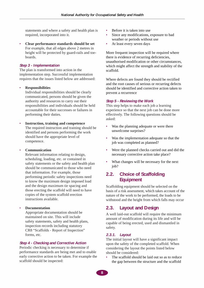
Maintaining scaffolding in a safe condition requiresactive management. The high rate of activity andchange on construction sites, together with the highrisk associated with scaffolding work requires ahigh level of safety management to preventaccidents and ill-health. The five steps listed belowprovide a practical template for the systematicmanagement of scaffolding operations.
Figure 3: Scaffolding Management
Step 1 - Scaffolding PolicyThe contractor should define a policy in relation toscaffolding. The policy should:
• Include a commitment to put measures in placeto protect employees, others at work andmembers of the public from the risks associatedwith scaffolding
• Require that competent persons be employed toerect, maintain and dismantle scaffolds.
• Include a commitment to comply with relevanthealth and safety legislation, including theSafety Health and Welfare at Work(Construction) Regulations, 1995 and relevantCodes of Practice and guidelines
• Clearly place the management of scaffolding asa prime responsibility of site management
• Include a commitment to provide appropriateresources to implement the policy
Step 2 - Planning The scaffolding erection, use and dismantlingstages should be planned so as to minimise the risks
involved. The planning process should address theareas listed below:
• The relevant legal and other requirementsshould be identifiedThe major legal requirements applying arethose contained in the Safety Health andWelfare at Work (Construction) Regulations,1995 and the Safety Health and Welfare atWork Act, 1989. Where system scaffolds areused, the manufacturer’s requirements shouldbe identified.
• The job should be defined The ground preparation, layout, scheduling,loading, access, tying arrangements and otherrequirements of the particular job should all bedefined.
• Responsibilities should be assigned Organisations or individuals with responsibilityfor performing specific tasks and duties relatingto the control of scaffolding should beidentified.
• Hazards should be identifiedA hazard is anything that can cause harm.Hazards should be systematically identified foreach project.
• Risks should be assessedWhen assessing the risks associated with theidentified hazards, account should be taken ofboth the likelihood of harm occurring and theseverity of the resulting injuries. (See 1.7)
• Risks should be eliminated or reducedIn reducing the risk the preferred solutions arecollective controls, e.g. protective barriers thatprotect everybody from falling; less preferredare administrative controls which seek to reducerisk by adherence to instructions or procedures,and least preferred are solutions which relysolely on the use of personal protectiveequipment, e.g. harnesses or safety helmets orsafety signs.
• The identified hazards and the necessaryprecautions should be written down These should be written in the safety statementsor site specific amendments to the safety
7
Code of Practice for Access and Working Scaffolds
2. Management and Control of Scaffolding
Policy
ReviewPlanning
Checking & Action Implementation
statements and where a safety and health plan isrequired, incorporated into it.
• Clear performance standards should be setFor example, that all edges above 2 metres inheight will be protected by guard-rails and toe-boards.
Step 3 - ImplementationThe plan is transformed into action in theimplementation step. Successful implementationrequires that the issues listed below are addressed:
• ResponsibilitiesIndividual responsibilities should be clearlycommunicated, persons should be given theauthority and resources to carry out theirresponsibilities and individuals should be heldaccountable for their successes or failures inperforming their duties.
• Instruction, training and competenceThe required instruction and training should beidentified and persons performing the workshould have the appropriate level ofcompetence.
• CommunicationRelevant information relating to design,scheduling, loading, etc. or contained in safety statements or the safety and health planshould be communicated to those who need that information. For example, thoseperforming periodic safety inspections need to know the maximum design imposed load and the design maximum tie spacing and those erecting the scaffold will need to havecopies of the system scaffold erectioninstructions available.
• DocumentationAppropriate documentation should bemaintained on site. This will include safety statements, safety and health plans,inspection records including statutory CR8 “Scaffolds - Report of Inspection” forms, etc.
Step 4 - Checking and Corrective Action Periodic checking is necessary to determine ifperformance standards are being met and to enableearly corrective action to be taken. For example thescaffold should be inspected:
• Before it is taken into use• Since any modifications, exposure to bad
weather or periods without use • At least every seven days
More frequent inspection will be required wherethere is evidence of recurring deficiencies,unauthorised modification or other circumstances,which might affect the strength and stability of thescaffold.
Where defects are found they should be rectifiedand the root causes of serious or recurring defectsshould be identified and corrective action taken toprevent a recurrence
Step 5 - Reviewing the WorkThis step helps to make each job a learningexperience so that the next job can be done moreeffectively. The following questions should beasked:
• Was the planning adequate or were thereunwelcome surprises?
• Was the implementation adequate so that thejob was completed as planned?
• Were the planned checks carried out and did thenecessary corrective action take place?
• What changes will be necessary for the nextjob?
2.2. Choice of ScaffoldingEquipment
Scaffolding equipment should be selected on thebasis of a risk assessment, which takes account of thenature of the work to be performed, the loads to bewithstood and the height from which falls may occur
2.3. Layout and DesignA well laid-out scaffold will require the minimumamount of modification during its life and will becapable of being erected, used and dismantled insafety.
2.3.1. LayoutThe initial layout will have a significant impactupon the safety of the completed scaffold. Whenconsidering the layout the points listed belowshould be considered:• The scaffold should be laid out so as to reduce
the gap between the structure and the scaffold
8
National Authority for Occupational Safety and Health
to a minimum, except where guard-rails will beerected adjacent to the structure.
• The standards should be positioned so as toavoid manhole lids or shallow drains whichmay not be able to sustain the scaffold loading.
2.3.2. Structural Design of ScaffoldsSystem scaffolds, designed and manufactured inaccordance with IS/HD 1000 or an equivalentstandard, may be constructed without furthercalculations provided they are constructed inaccordance with the system scaffoldingmanufacturer’s instructions and restrictions.
Basic simple unsheeted tube and fitting scaffoldsmay be constructed to a height of 50 metres withoutcalculations provided they are constructed inaccordance with Sections 2 and 3 of this code anddo not carry greater loads nor have greater baylengths than those given in Table 4: Maximum BayCentres for Tube and Fitting Scaffolding inAppendix A: Tube and Fitting Scaffolds on page 36.
A further recommendation is that scaffold workingplatforms are not subjected to loading of materialsby mechanical means, e.g. by rough terrain fork lifttrucks.
All other forms of scaffold, including specialscaffolds, should be subject to design andcalculation by a competent person such as achartered structural engineer with appropriateexperience or by another competent person.
Section 5 of BS 5973; 1993 gives guidance onspecial scaffolds which are subject to calculationand Section 6 and Appendix B of BS 5973; 1993give technical data and examples of calculations.
For illustrative purposes, typical examples wheredesign and calculation may be necessary include:
• Sheeted system scaffolds• System scaffolds erected in areas where the
wind pressure exceeds that specified in IS/HD1000 or where the design wind speed exceedsthat specified by the scaffolding manufacturer
• System scaffolds where the maximum height,tie spacing, imposed loads, bay widths ornumber of working lifts exceeds themanufacturer’s recommendations
• Scaffolds where the tie or anchorage capacity isless than 6.25 kN (637 kg)
• Tube and fitting scaffolds where the maximumtie spacing exceeds that of Table 5: Frequencyof ties in square metres per tie for tube andfitting scaffolds in Appendix A on page 35.
• Tube and fitting scaffolds where the heightexceeds 50 metres for unsheeted scaffolds and25 metres for sheeted scaffolds
• Scaffolds with temporary roofs•· Scaffolds subjected to impact e.g. mechanical
loading of heavy materials onto workingplatforms.
• Scaffolds where the bottom transoms or ledgershave been omitted to allow pedestrian access
• Scaffolds where the first line of ties is morethan 4 metres above the base of the scaffold
• Scaffold buttresses• Special scaffolds including: loading bays,
protection fans, nets, pavement frames,cantilever scaffolds, truss-out scaffolds, freestanding external towers, hoist towers, slungscaffolds, pedestrian bridges and walkways,temporary ramps and elevated roadways, masts,lifting gantries, temporary buildings and roofs.
• Scaffolds where the required bracing is omitted• Scaffolds where the allowable bearing pressure
of the ground may not be adequate to supportthe scaffold
2.3.3. Building Design and Scaffold ErectionThe design of the temporary works can be affectedby, or can affect, the design of the permanentworks. For example, many system scaffolds requirethat every standard be tied to the structure underconstruction or to some other substantial structure.The best arrangement is where the ties can be left inplace until final dismantling of the scaffold.
The project supervisor construction stage should, atan early stage, seek the co-operation of buildingdesigners in permitting the attachment of non-movable ties to the building structure where suchattachment is reasonably practicable.
Timely provision of adequate details of theproposed permanent works is necessary in order toproperly schedule the construction of the temporaryworks and Project Supervisors should co-ordinatethese matters.
For example, project supervisors should ensure thatinformation on the proposed location of adjacentdrains or other excavations is available to thetemporary works designer or contractor so that they
9
Code of Practice for Access and Working Scaffolds
can ensure that the foundations of the relevantscaffolds are not undermined. Where suchinformation is not received in a timely manner, theproject supervisors should ensure that adequate timeis allowed for the safe completion of the project.
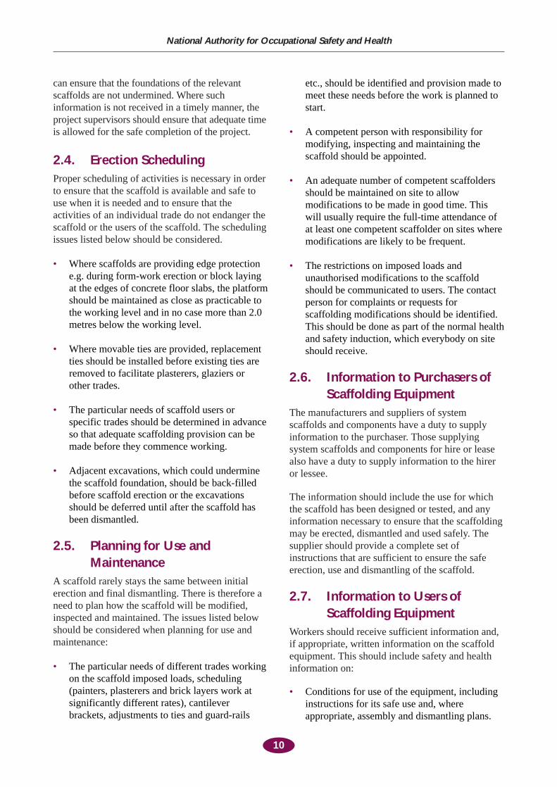
2.4. Erection SchedulingProper scheduling of activities is necessary in orderto ensure that the scaffold is available and safe touse when it is needed and to ensure that theactivities of an individual trade do not endanger thescaffold or the users of the scaffold. The schedulingissues listed below should be considered.
• Where scaffolds are providing edge protectione.g. during form-work erection or block layingat the edges of concrete floor slabs, the platformshould be maintained as close as practicable tothe working level and in no case more than 2.0metres below the working level.
• Where movable ties are provided, replacementties should be installed before existing ties areremoved to facilitate plasterers, glaziers orother trades.
• The particular needs of scaffold users orspecific trades should be determined in advanceso that adequate scaffolding provision can bemade before they commence working.
• Adjacent excavations, which could underminethe scaffold foundation, should be back-filledbefore scaffold erection or the excavationsshould be deferred until after the scaffold hasbeen dismantled.
2.5. Planning for Use andMaintenance
A scaffold rarely stays the same between initialerection and final dismantling. There is therefore aneed to plan how the scaffold will be modified,inspected and maintained. The issues listed belowshould be considered when planning for use andmaintenance:
• The particular needs of different trades workingon the scaffold imposed loads, scheduling(painters, plasterers and brick layers work atsignificantly different rates), cantileverbrackets, adjustments to ties and guard-rails
etc., should be identified and provision made tomeet these needs before the work is planned tostart.
• A competent person with responsibility formodifying, inspecting and maintaining thescaffold should be appointed.
• An adequate number of competent scaffoldersshould be maintained on site to allowmodifications to be made in good time. Thiswill usually require the full-time attendance ofat least one competent scaffolder on sites wheremodifications are likely to be frequent.
• The restrictions on imposed loads andunauthorised modifications to the scaffoldshould be communicated to users. The contactperson for complaints or requests forscaffolding modifications should be identified.This should be done as part of the normal healthand safety induction, which everybody on siteshould receive.
2.6. Information to Purchasers ofScaffolding Equipment
The manufacturers and suppliers of systemscaffolds and components have a duty to supplyinformation to the purchaser. Those supplyingsystem scaffolds and components for hire or leasealso have a duty to supply information to the hireror lessee.
The information should include the use for whichthe scaffold has been designed or tested, and anyinformation necessary to ensure that the scaffoldingmay be erected, dismantled and used safely. Thesupplier should provide a complete set ofinstructions that are sufficient to ensure the safeerection, use and dismantling of the scaffold.
2.7. Information to Users ofScaffolding Equipment
Workers should receive sufficient information and,if appropriate, written information on the scaffoldequipment. This should include safety and healthinformation on:
• Conditions for use of the equipment, includinginstructions for its safe use and, whereappropriate, assembly and dismantling plans.
10
National Authority for Occupational Safety and Health

• Any unusual conditions which can be foreseen• Any conclusions to be drawn from experience
of using the type of scaffold equipment
The information provided should becomprehensible to the workers concerned.
11
Code of Practice for Access and Working Scaffolds
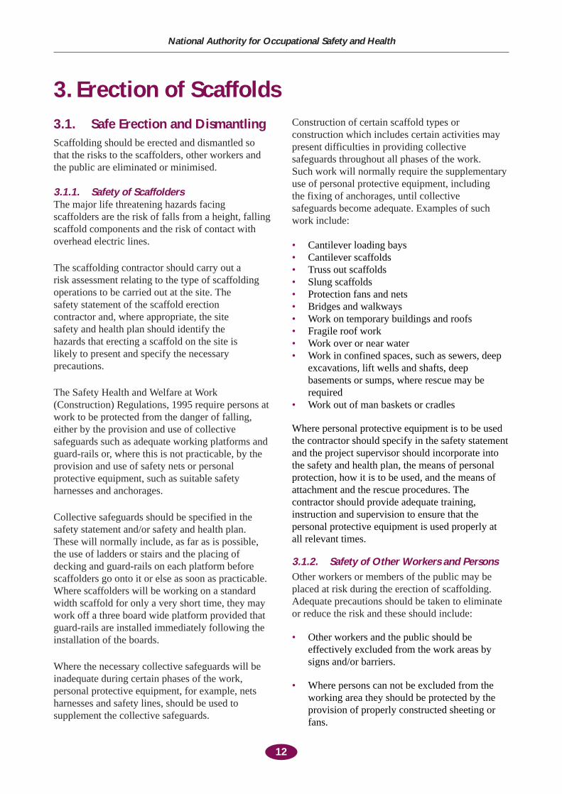
3.1. Safe Erection and DismantlingScaffolding should be erected and dismantled sothat the risks to the scaffolders, other workers andthe public are eliminated or minimised.
3.1.1. Safety of ScaffoldersThe major life threatening hazards facingscaffolders are the risk of falls from a height, fallingscaffold components and the risk of contact withoverhead electric lines.
The scaffolding contractor should carry out a risk assessment relating to the type of scaffoldingoperations to be carried out at the site. The safety statement of the scaffold erection contractor and, where appropriate, the site safety and health plan should identify the hazards that erecting a scaffold on the site is likely to present and specify the necessaryprecautions.
The Safety Health and Welfare at Work(Construction) Regulations, 1995 require persons atwork to be protected from the danger of falling,either by the provision and use of collectivesafeguards such as adequate working platforms andguard-rails or, where this is not practicable, by theprovision and use of safety nets or personalprotective equipment, such as suitable safetyharnesses and anchorages.
Collective safeguards should be specified in thesafety statement and/or safety and health plan.These will normally include, as far as is possible,the use of ladders or stairs and the placing ofdecking and guard-rails on each platform beforescaffolders go onto it or else as soon as practicable.Where scaffolders will be working on a standardwidth scaffold for only a very short time, they maywork off a three board wide platform provided thatguard-rails are installed immediately following theinstallation of the boards.
Where the necessary collective safeguards will beinadequate during certain phases of the work,personal protective equipment, for example, netsharnesses and safety lines, should be used tosupplement the collective safeguards.
Construction of certain scaffold types orconstruction which includes certain activities maypresent difficulties in providing collectivesafeguards throughout all phases of the work. Such work will normally require the supplementaryuse of personal protective equipment, including the fixing of anchorages, until collective safeguards become adequate. Examples of suchwork include:
• Cantilever loading bays• Cantilever scaffolds• Truss out scaffolds• Slung scaffolds• Protection fans and nets• Bridges and walkways• Work on temporary buildings and roofs• Fragile roof work• Work over or near water• Work in confined spaces, such as sewers, deep
excavations, lift wells and shafts, deepbasements or sumps, where rescue may berequired
• Work out of man baskets or cradles
Where personal protective equipment is to be usedthe contractor should specify in the safety statementand the project supervisor should incorporate intothe safety and health plan, the means of personalprotection, how it is to be used, and the means ofattachment and the rescue procedures. Thecontractor should provide adequate training,instruction and supervision to ensure that thepersonal protective equipment is used properly atall relevant times.
3.1.2. Safety of Other Workers and PersonsOther workers or members of the public may beplaced at risk during the erection of scaffolding.Adequate precautions should be taken to eliminateor reduce the risk and these should include:
• Other workers and the public should beeffectively excluded from the work areas bysigns and/or barriers.
• Where persons can not be excluded from theworking area they should be protected by theprovision of properly constructed sheeting orfans.
12
National Authority for Occupational Safety and Health
3. Erection of Scaffolds
3.1.3. Incomplete ScaffoldingA scaffold should be constructed so that it is leftcomplete and is properly tied, braced and deckedand has adequate guard-rails and toe boards. Wherea scaffold is left incomplete there is a danger that itwill be used to gain access while it is in adangerous condition.
Where a scaffold is partly erected or dismantled, aprominent warning notice should be placed at eachpotential access point and barriers should be placedto prevent access. Such notices should be removedwhen they are no longer required.
The most effective way of preventing access to anincomplete scaffold is by removing all decking andladders. Incomplete scaffolds should be completedor dismantled as soon as practicable.
3.2. Materials
3.2.1. Inspection Prior to UseAll materials should be inspected before use. Theinspection should be performed before despatch tothe site or upon arrival at the site. An area shouldbe set aside for damaged or defective material.Signs should be erected indicating that the materialis defective and is not to be used. A check-list isprovided in Appendix B on page 39 to assist thisexamination.
3.2.2. StandardsStandards are the vertical tubular members thattransmit the vertical loads of the scaffold to thefoundations. The spacing of system scaffoldingstandards should follow the recommendations inthe manufacturer’s erection instructions.
For tube and fitting scaffolds, the spacing betweenstandards given in Table 4: Maximum Bay Centresfor Tube and Fitting Scaffolding on page 36 shouldnot be exceeded.
3.2.3. TransomsTransoms run at right angles to the structure,joining the inside and outside ledgers andsupporting the scaffold boards. Intermediatetransoms may be required to support the scaffoldplatform between main transoms.
The lowest transom should be installed as close aspossible to the bottom of the standards, otherwise,the load carrying capacity of the scaffold will besignificantly reduced. The bottom transom is
sometimes omitted to permit pedestrians to walkthrough the scaffold. The risk assessment and safetyand health plan may indicate other solutions such aserection of a protected hoarding outside thescaffold, which do not compromise the strength ofthe scaffold.
3.2.4. LedgersLedgers run along the inside and outside of the scaffold joining each pair of standards toanother pair. They also support any intermediatetransoms. The load carrying capacity of the scaffold will be significantly reduced where it is not possible to place the first ledger at the base ofthe standards. (See 3.2.3.) Tube and fitting ledgersshould be joined with sleeve couplings or withexpanding joint pins where tension is not likely tooccur.
3.2.5. CouplersCouplers are used in conjunction with systemscaffolds mainly for the attachment of ties, planbracing and cross (ledger) bracing. The proper useof appropriate couplers is therefore important to thestability of the scaffold. Couplers, when new,should comply with the requirements of therelevant European or British Standard. Fittings forwhich there is no standard should only be used inaccordance with the recommendations and dataprovided by the manufacturer or supplier.
The safe working loads, listed below, apply tocouplers marked with EN 74 and where appropriate‘A’ or ‘B’.
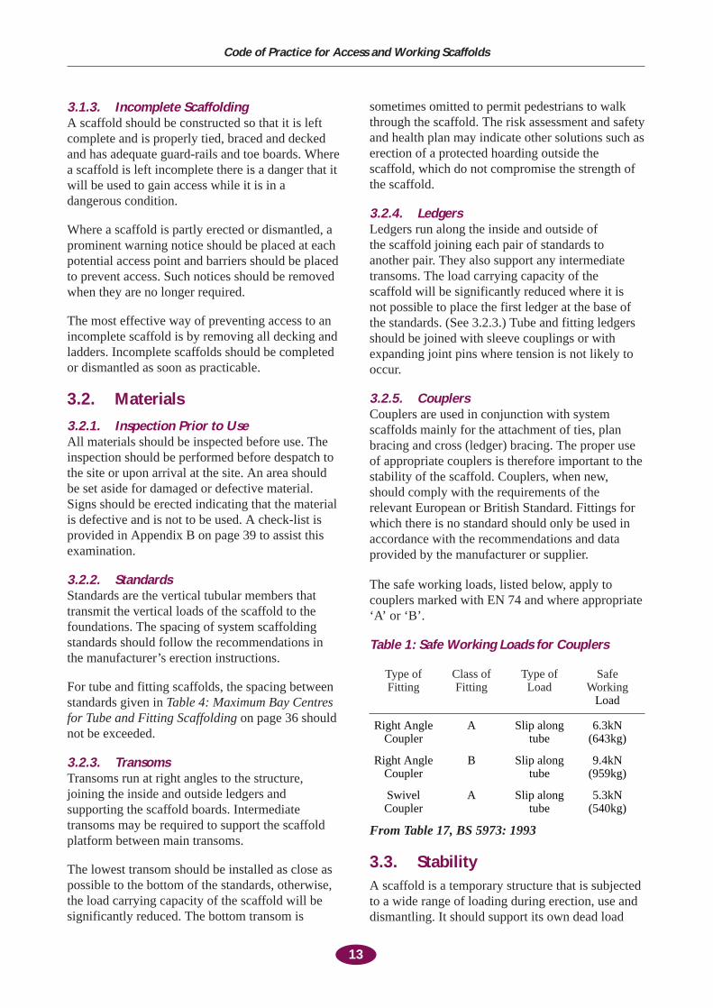
Table 1: Safe Working Loads for Couplers
Type of Class of Type of Safe Fitting Fitting Load Working
Load
Right Angle A Slip along 6.3kNCoupler tube (643kg)
Right Angle B Slip along 9.4kNCoupler tube (959kg)
Swivel A Slip along 5.3kNCoupler tube (540kg)
From Table 17, BS 5973: 1993
3.3. StabilityA scaffold is a temporary structure that is subjectedto a wide range of loading during erection, use anddismantling. It should support its own dead load
13
Code of Practice for Access and Working Scaffolds
and live loads from construction materials, workersand tools, shock loads from material placement andwind loads.
Where failures occur, large areas of scaffolding can collapse quite suddenly. Scaffolds can collapse because of poor construction or misuse,leading to them being loaded beyond their safecapacity to support the load. Common faults are poor foundations, inadequate tying and bracing, overloading and the removal of ties andbracing.
Scaffold stability depends on carefully followingthe system scaffold manufacturer’s instructions andthe provisions of this code or other equivalentstandards. In particular, the issues, listed below,should be addressed:
• The foundations should be adequate (See 3.3.1)
• The scaffold should be tied to the permanentstructure or to buttresses (See 3.3.2)
• The scaffold should be braced (See 3.3.4)
• The scaffold should not be overloaded (See 3.8)
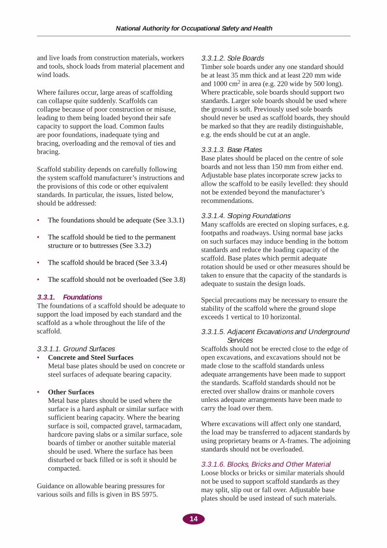
3.3.1. FoundationsThe foundations of a scaffold should be adequate tosupport the load imposed by each standard and thescaffold as a whole throughout the life of thescaffold.
3.3.1.1. Ground Surfaces• Concrete and Steel Surfaces
Metal base plates should be used on concrete orsteel surfaces of adequate bearing capacity.
• Other SurfacesMetal base plates should be used where thesurface is a hard asphalt or similar surface withsufficient bearing capacity. Where the bearingsurface is soil, compacted gravel, tarmacadam,hardcore paving slabs or a similar surface, soleboards of timber or another suitable materialshould be used. Where the surface has beendisturbed or back filled or is soft it should becompacted.
Guidance on allowable bearing pressures forvarious soils and fills is given in BS 5975.
3.3.1.2. Sole BoardsTimber sole boards under any one standard shouldbe at least 35 mm thick and at least 220 mm wideand 1000 cm2 in area (e.g. 220 wide by 500 long).Where practicable, sole boards should support twostandards. Larger sole boards should be used wherethe ground is soft. Previously used sole boardsshould never be used as scaffold boards, they shouldbe marked so that they are readily distinguishable,e.g. the ends should be cut at an angle.
3.3.1.3. Base PlatesBase plates should be placed on the centre of soleboards and not less than 150 mm from either end.Adjustable base plates incorporate screw jacks toallow the scaffold to be easily levelled: they shouldnot be extended beyond the manufacturer’srecommendations.
3.3.1.4. Sloping FoundationsMany scaffolds are erected on sloping surfaces, e.g.footpaths and roadways. Using normal base jackson such surfaces may induce bending in the bottomstandards and reduce the loading capacity of thescaffold. Base plates which permit adequaterotation should be used or other measures should betaken to ensure that the capacity of the standards isadequate to sustain the design loads.
Special precautions may be necessary to ensure thestability of the scaffold where the ground slopeexceeds 1 vertical to 10 horizontal.
3.3.1.5. Adjacent Excavations and UndergroundServices
Scaffolds should not be erected close to the edge ofopen excavations, and excavations should not bemade close to the scaffold standards unlessadequate arrangements have been made to supportthe standards. Scaffold standards should not beerected over shallow drains or manhole coversunless adequate arrangements have been made tocarry the load over them.
Where excavations will affect only one standard,the load may be transferred to adjacent standards byusing proprietary beams or A-frames. The adjoiningstandards should not be overloaded.
3.3.1.6. Blocks, Bricks and Other MaterialLoose blocks or bricks or similar materials shouldnot be used to support scaffold standards as theymay split, slip out or fall over. Adjustable baseplates should be used instead of such materials.
14
National Authority for Occupational Safety and Health
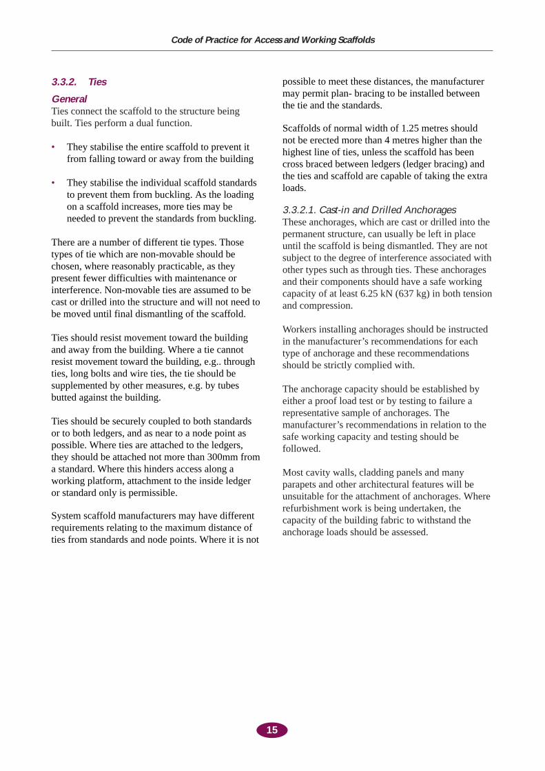
3.3.2. Ties
GeneralTies connect the scaffold to the structure beingbuilt. Ties perform a dual function.
• They stabilise the entire scaffold to prevent itfrom falling toward or away from the building
• They stabilise the individual scaffold standardsto prevent them from buckling. As the loadingon a scaffold increases, more ties may beneeded to prevent the standards from buckling.
There are a number of different tie types. Thosetypes of tie which are non-movable should bechosen, where reasonably practicable, as theypresent fewer difficulties with maintenance orinterference. Non-movable ties are assumed to becast or drilled into the structure and will not need tobe moved until final dismantling of the scaffold.
Ties should resist movement toward the buildingand away from the building. Where a tie cannotresist movement toward the building, e.g.. throughties, long bolts and wire ties, the tie should besupplemented by other measures, e.g. by tubesbutted against the building.
Ties should be securely coupled to both standardsor to both ledgers, and as near to a node point aspossible. Where ties are attached to the ledgers,they should be attached not more than 300mm froma standard. Where this hinders access along aworking platform, attachment to the inside ledgeror standard only is permissible.
System scaffold manufacturers may have differentrequirements relating to the maximum distance ofties from standards and node points. Where it is not
possible to meet these distances, the manufacturermay permit plan- bracing to be installed betweenthe tie and the standards.
Scaffolds of normal width of 1.25 metres shouldnot be erected more than 4 metres higher than thehighest line of ties, unless the scaffold has beencross braced between ledgers (ledger bracing) andthe ties and scaffold are capable of taking the extraloads.
3.3.2.1. Cast-in and Drilled AnchoragesThese anchorages, which are cast or drilled into thepermanent structure, can usually be left in placeuntil the scaffold is being dismantled. They are notsubject to the degree of interference associated withother types such as through ties. These anchoragesand their components should have a safe workingcapacity of at least 6.25 kN (637 kg) in both tensionand compression.
Workers installing anchorages should be instructedin the manufacturer’s recommendations for eachtype of anchorage and these recommendationsshould be strictly complied with.
The anchorage capacity should be established byeither a proof load test or by testing to failure arepresentative sample of anchorages. Themanufacturer’s recommendations in relation to thesafe working capacity and testing should befollowed.
Most cavity walls, cladding panels and manyparapets and other architectural features will beunsuitable for the attachment of anchorages. Whererefurbishment work is being undertaken, thecapacity of the building fabric to withstand theanchorage loads should be assessed.
15
Code of Practice for Access and Working Scaffolds
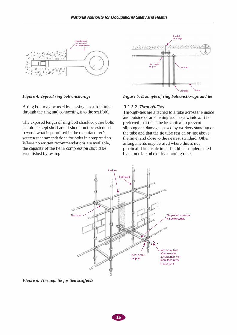
A ring bolt may be used by passing a scaffold tubethrough the ring and connecting it to the scaffold.
The exposed length of ring-bolt shank or other boltsshould be kept short and it should not be extendedbeyond what is permitted in the manufacturer’swritten recommendations for bolts in compression.Where no written recommendations are available,the capacity of the tie in compression should beestablished by testing.
3.3.2.2. Through-TiesThrough-ties are attached to a tube across the insideand outside of an opening such as a window. It ispreferred that this tube be vertical to preventslipping and damage caused by workers standing onthe tube and that the tie tube rest on or just abovethe lintel and close to the nearest standard. Otherarrangements may be used where this is notpractical. The inside tube should be supplementedby an outside tube or by a butting tube.
16
National Authority for Occupational Safety and Health
Ring boltanchorage
Right anglecoupler Transom
Standard Ledger
Figure 4. Typical ring bolt anchorage
Do not exceedmanufacturer’srecommendations
Figure 5. Example of ring bolt anchorage and tie
Not more than300mm or in accordance withmanufacturer’sinstructions.
Right anglecoupler
Tie placed close to window reveal.
Standard
Ledger
Transom
Figure 6. Through tie for tied scaffolds
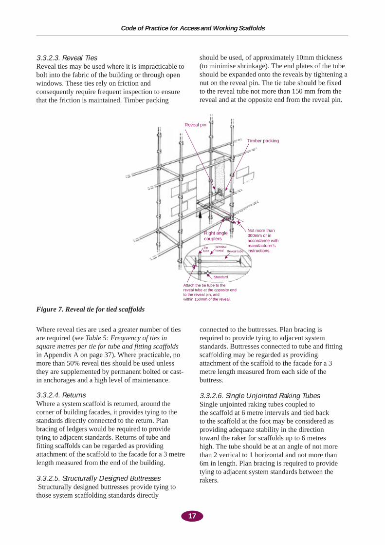
3.3.2.3. Reveal TiesReveal ties may be used where it is impracticable tobolt into the fabric of the building or through openwindows. These ties rely on friction andconsequently require frequent inspection to ensurethat the friction is maintained. Timber packing
should be used, of approximately 10mm thickness(to minimise shrinkage). The end plates of the tubeshould be expanded onto the reveals by tightening anut on the reveal pin. The tie tube should be fixedto the reveal tube not more than 150 mm from thereveal and at the opposite end from the reveal pin.
17
Code of Practice for Access and Working Scaffolds
Reveal pin
Timber packing
Not more than300mm or in accordance withmanufacturer’sinstructions.
Right anglecouplers
Tie tube
Windowreveal Reveal tube
Attach the tie tube to the reveal tube at the opposite end to the reveal pin, and within 150mm of the reveal.
Standard
Figure 7. Reveal tie for tied scaffolds
Where reveal ties are used a greater number of tiesare required (see Table 5: Frequency of ties insquare metres per tie for tube and fitting scaffoldsin Appendix A on page 37). Where practicable, nomore than 50% reveal ties should be used unlessthey are supplemented by permanent bolted or cast-in anchorages and a high level of maintenance.
3.3.2.4. Returns Where a system scaffold is returned, around thecorner of building facades, it provides tying to thestandards directly connected to the return. Planbracing of ledgers would be required to providetying to adjacent standards. Returns of tube andfitting scaffolds can be regarded as providingattachment of the scaffold to the facade for a 3 metrelength measured from the end of the building.
3.3.2.5. Structurally Designed ButtressesStructurally designed buttresses provide tying tothose system scaffolding standards directly
connected to the buttresses. Plan bracing is required to provide tying to adjacent systemstandards. Buttresses connected to tube and fittingscaffolding may be regarded as providingattachment of the scaffold to the facade for a 3metre length measured from each side of thebuttress.
3.3.2.6. Single Unjointed Raking Tubes Single unjointed raking tubes coupled to the scaffold at 6 metre intervals and tied back to the scaffold at the foot may be considered asproviding adequate stability in the direction toward the raker for scaffolds up to 6 metres high. The tube should be at an angle of not morethan 2 vertical to 1 horizontal and not more than 6m in length. Plan bracing is required to providetying to adjacent system standards between therakers.
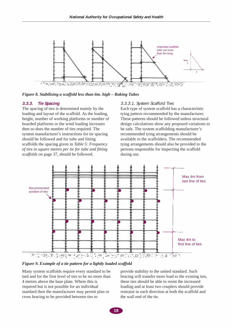
3.3.3. Tie Spacing The spacing of ties is determined mainly by theloading and layout of the scaffold. As the loading,height, number of working platforms or number ofboarded platforms or the wind loading increasesthen so does the number of ties required. Thesystem manufacturer’s instructions for tie spacingshould be followed and for tube and fittingscaffolds the spacing given in Table 5: Frequencyof ties in square metres per tie for tube and fittingscaffolds on page 37, should be followed.
3.3.3.1. System Scaffold Ties Each type of system scaffold has a characteristictying pattern recommended by the manufacturer.These patterns should be followed unless structuraldesign calculations show any proposed variations tobe safe. The system scaffolding manufacturer’srecommended tying arrangements should beavailable to the scaffolders. The recommendedtying arrangements should also be provided to thepersons responsible for inspecting the scaffoldduring use.
18
National Authority for Occupational Safety and Health
Unjointed scaffoldtube not morethan 6m long.
Figure 8. Stabilising a scaffold less than 6m. high – Raking Tubes
Recommendedposition of ties
Max 4m fromlast line of ties
Max 4m tofirst line of ties
Figure 9. Example of a tie pattern for a lightly loaded scaffold
Many system scaffolds require every standard to betied and for the first level of ties to be no more than4 metres above the base plate. Where this isrequired but is not possible for an individualstandard then the manufacturer may permit plan orcross bracing to be provided between ties to
provide stability to the untied standard. Suchbracing will transfer more load to the existing ties,these ties should be able to resist the increasedloading and at least two couplers should providerestraint in each direction at both the scaffold andthe wall end of the tie.
3.3.3.2. Tube and Fitting Scaffold TiesThe number of ties recommended in Table 5:Frequency of ties in square metres per tie for tubeand fitting scaffolds on page 37, should, as aminimum, be installed. When tying sheetedscaffolds in accordance with Table 5 ensure that thecoupler capacity is adequate and ensure that thereare at least two couplers providing restraint in eachdirection at both the scaffold and the wall end of thetie.
The frequencies in Table 5 do not apply where thedesign wind speed is greater than 39 m/s (140 km/h)
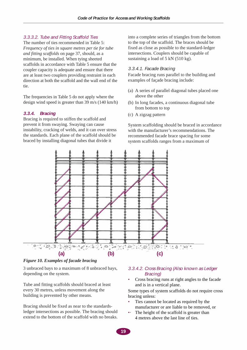
3.3.4. BracingBracing is required to stiffen the scaffold andprevent it from swaying. Swaying can causeinstability, cracking of welds, and it can over stressthe standards. Each plane of the scaffold should bebraced by installing diagonal tubes that divide it
into a complete series of triangles from the bottomto the top of the scaffold. The braces should befixed as close as possible to the standard-ledgerintersections. Couplers should be capable ofsustaining a load of 5 kN (510 kg).
3.3.4.1. Facade BracingFacade bracing runs parallel to the building andexamples of façade bracing include:
(a) A series of parallel diagonal tubes placed oneabove the other
(b) In long facades, a continuous diagonal tubefrom bottom to top
(c) A zigzag pattern
System scaffolding should be braced in accordancewith the manufacturer’s recommendations. Therecommended facade brace spacing for somesystem scaffolds ranges from a maximum of
19
Code of Practice for Access and Working Scaffolds
Figure 10. Examples of facade bracing
3 unbraced bays to a maximum of 8 unbraced bays,depending on the system.
Tube and fitting scaffolds should braced at leastevery 30 metres, unless movement along thebuilding is prevented by other means.
Bracing should be fixed as near to the standards-ledger intersections as possible. The bracing shouldextend to the bottom of the scaffold with no breaks.
3.3.4.2. Cross Bracing (Also known as LedgerBracing)
• Cross bracing runs at right angles to the facadeand is in a vertical plane.
Some types of system scaffolds do not require crossbracing unless:• Ties cannot be located as required by the
manufacturer or are liable to be removed, or •· The height of the scaffold is greater than
4 metres above the last line of ties.
(a) (b) (c)
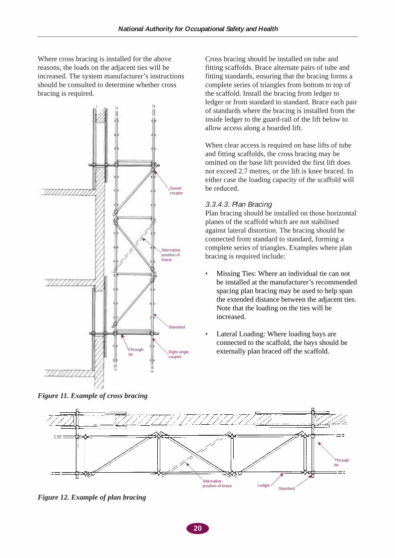
Where cross bracing is installed for the abovereasons, the loads on the adjacent ties will beincreased. The system manufacturer’s instructionsshould be consulted to determine whether crossbracing is required.
Cross bracing should be installed on tube andfitting scaffolds. Brace alternate pairs of tube andfitting standards, ensuring that the bracing forms acomplete series of triangles from bottom to top ofthe scaffold. Install the bracing from ledger toledger or from standard to standard. Brace each pairof standards where the bracing is installed from theinside ledger to the guard-rail of the lift below toallow access along a boarded lift.
When clear access is required on base lifts of tubeand fitting scaffolds, the cross bracing may beomitted on the base lift provided the first lift doesnot exceed 2.7 metres, or the lift is knee braced. Ineither case the loading capacity of the scaffold willbe reduced.
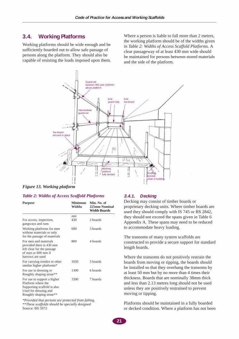
3.3.4.3. Plan BracingPlan bracing should be installed on those horizontalplanes of the scaffold which are not stabilisedagainst lateral distortion. The bracing should beconnected from standard to standard, forming acomplete series of triangles. Examples where planbracing is required include:
• Missing Ties: Where an individual tie can notbe installed at the manufacturer’s recommendedspacing plan bracing may be used to help spanthe extended distance between the adjacent ties.Note that the loading on the ties will beincreased.
• Lateral Loading: Where loading bays areconnected to the scaffold, the bays should beexternally plan braced off the scaffold.
20
National Authority for Occupational Safety and Health
Swivel coupler
Alternativeposition ofbrace
Standard
Right anglecoupler
Throughtie
Alternativeposition of brace Ledger
Standard
Throughtie
Figure 12. Example of plan bracing
Figure 11. Example of cross bracing
21
Code of Practice for Access and Working Scaffolds
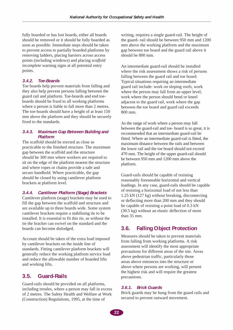
3.4. Working PlatformsWorking platforms should be wide enough and besufficiently boarded out to allow safe passage ofpersons along the platform. They should also becapable of resisting the loads imposed upon them.
Where a person is liable to fall more than 2 metres,the working platform should be of the widths givenin Table 2: Widths of Access Scaffold Platforms. Aclear passageway of at least 430 mm wide shouldbe maintained for persons between stored materialsand the side of the platform.
Scaffolderected close to building
Workingplatformfully decked
Toe-boardsecured in place
Intermediateguard-rail
Guard-railbetween 950 and 1200mmabove platform
Endguard-rails
Endtoe-board
Figure 13. Working platform
Table 2: Widths of Access Scaffold Platforms
Purpose Minimum Min. No. of Widths 225mm Nominal
Width Boards
mmFor access, inspection, 430 2 boardsgangways and runs
Working platforms for men 600 3 boardswithout materials or onlyfor the passage of materials
For men and materials 800 4 boardsprovided there is 430 mm left clear for the passage of men or 600 mm if barrows are used
For carrying trestles or other 1050 5 boardssimilar higher platforms*
For use in dressing or 1300 6 boardsRoughly shaping stone**
For use to support a higher 1500 7 boardsPlatform where the Supporting scaffold is also Used for dressing and Roughly shaping stone**
*Provided that persons are protected from falling.**These scaffolds should be specially designedSource: BS 5973
3.4.1. Decking Decking may consist of timber boards orproprietary decking units. Where timber boards areused they should comply with IS 745 or BS 2842,they should not exceed the spans given in Table 6Appendix A. These spans may need to be reducedto accommodate heavy loading.
The transoms of many system scaffolds areconstructed to provide a secure support for standardlength boards.
Where the transoms do not positively restrain theboards from moving or tipping, the boards shouldbe installed so that they overhang the transoms byat least 50 mm but by no more than 4 times theirthickness. Boards that are nominally 38mm thickand less than 2.13 metres long should not be usedunless they are positively restrained to preventmoving or tipping.
Platforms should be maintained in a fully boardedor decked condition. Where a platform has not been
fully boarded or has lost boards, either all boardsshould be removed or it should be fully boarded assoon as possible. Immediate steps should be takento prevent access to partially boarded platforms byremoving ladders, placing barriers across accesspoints (including windows) and placing scaffoldincomplete warning signs at all potential entrypoints.
3.4.2. Toe-BoardsToe boards help prevent materials from falling andthey also help prevent persons falling between theguard rail and platform. Toe-boards and end toe-boards should be fixed to all working platformswhere a person is liable to fall more than 2 metres.The toe-boards should have a height of at least 150mm above the platform and they should be securelyfixed to the standards.
3.4.3. Maximum Gap Between Building andPlatform
The scaffold should be erected as close aspracticable to the finished structure. The maximumgap between the scaffold and the structure should be 300 mm where workers are required to sit on the edge of the platform nearest the structureand where ropes or chains provide a safe and secure handhold. Where practicable, the gap should be closed by using cantilever platformbrackets at platform level.
3.4.4. Cantilever Platform (Stage) Brackets Cantilever platform (stage) brackets may be used tofill the gap between the scaffold and structure andare available up to three boards wide. Some systemcantilever brackets require a stabilising tie to beinstalled. It is essential to fit this tie, as without thetie the bracket can swivel on the standard and theboards can become dislodged.
Account should be taken of the extra load imposedby cantilever brackets on the inside line ofstandards. Fitting cantilever platform brackets willgenerally reduce the working platform service loadand reduce the allowable number of boarded liftsand working lifts.
3.5. Guard-Rails Guard-rails should be provided on all platforms,including trestles, where a person may fall in excessof 2 metres. The Safety Health and Welfare at Work(Construction) Regulations, 1995, at the time of
writing, requires a single guard-rail. The height ofthe guard- rail should be between 950 mm and 1200mm above the working platform and the maximumgap between toe board and the guard rail above itshould be 800 mm.
An intermediate guard-rail should be installedwhere the risk assessment shows a risk of personsfalling between the guard rail and toe board.Typical situations requiring an intermediate guard rail include: work on sloping roofs, workwhere the person may fall from an upper level,work where the person should bend or kneeladjacent to the guard rail, work where the gapbetween the toe board and guard rail exceeds 800 mm.
As the range of work where a person may fallbetween the guard-rail and toe- board is so great, it isrecommended that an intermediate guard-rail befitted. Where an intermediate guard-rail is fitted, themaximum distance between the rails and between the lower rail and the toe board should not exceed470 mm. The height of the upper guard-rail should be between 950 mm and 1200 mm above theplatform.
Guard-rails should be capable of resistingreasonably foreseeable horizontal and verticalloadings. In any case, guard-rails should be capableof resisting a horizontal load of not less than 1.25 kN (127 kg) without breaking, disconnectingor deflecting more than 200 mm and they should be capable of resisting a point load of 0.3 kN (30.5 kg) without an elastic deflection of more than 35 mm.
3.6. Falling Object ProtectionMeasures should be taken to prevent materials from falling from working platforms. A riskassessment will identify the most appropriateprecautions for different areas of the site. Areasabove pedestrian traffic, particularly those areas above entrances into the structure or above where persons are working, will present the highest risk and will require the greatestprecautions.
3.6.1. Brick GuardsBrick guards may be hung from the guard rails andsecured to prevent outward movement.
22
National Authority for Occupational Safety and Health
3.6.2. SheetingSheeting may consist of netting, corrugated sheetsor timber sheets. It should be fixed securely toprevent materials from passing through thesheeting. Sheeting should be inspected regularly,particularly after strong winds. Sheeting willsignificantly increase the wind loading on ascaffold and on the ties and tie couplers.
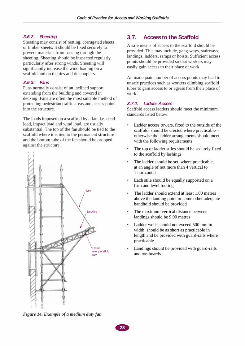
3.6.3. Fans Fans normally consist of an inclined supportextending from the building and covered indecking. Fans are often the most suitable method ofprotecting pedestrian traffic areas and access pointsinto the structure.
The loads imposed on a scaffold by a fan, i.e. deadload, impact load and wind load, are usuallysubstantial. The top of the fan should be tied to thescaffold where it is tied to the permanent structureand the bottom tube of the fan should be proppedagainst the structure.
3.7. Access to the ScaffoldA safe means of access to the scaffold should beprovided. This may include, gang-ways, stairways,landings, ladders, ramps or hoists. Sufficient accesspoints should be provided so that workers mayeasily gain access to their place of work.
An inadequate number of access points may lead tounsafe practices such as workers climbing scaffoldtubes to gain access to or egress from their place ofwork.
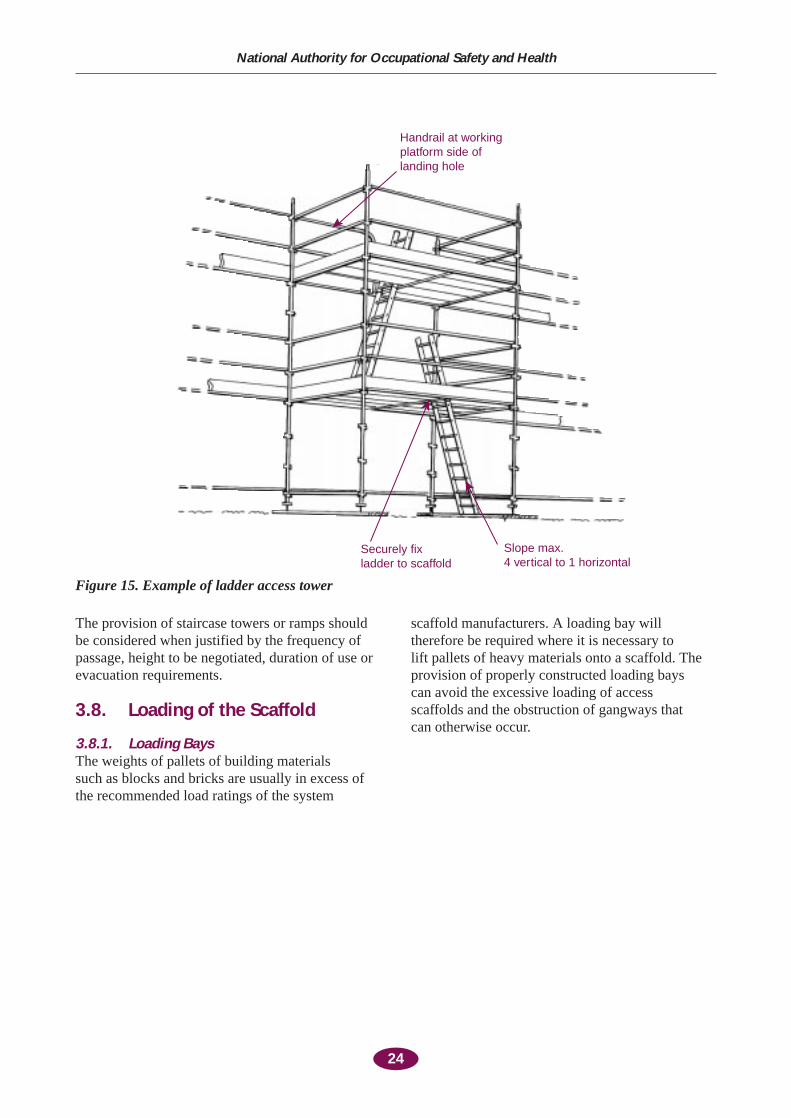
3.7.1. Ladder AccessScaffold access ladders should meet the minimumstandards listed below:
• Ladder access towers, fixed to the outside of thescaffold, should be erected where practicable –otherwise the ladder arrangements should meetwith the following requirements:
• The top of ladder stiles should be securely fixedto the scaffold by lashings
• The ladder should be set, where practicable, at an angle of not more than 4 vertical to 1 horizontal
• Each stile should be equally supported on afirm and level footing
• The ladder should extend at least 1.00 metresabove the landing point or some other adequatehandhold should be provided
• The maximum vertical distance betweenlandings should be 9.00 metres
• Ladder wells should not exceed 500 mm inwidth, should be as short as practicable inlength and be provided with guard-rails wherepracticable
• Landings should be provided with guard-railsand toe-boards
23
Code of Practice for Access and Working Scaffolds
Wire
Decking
Frameevery scaffoldbay
Figure 14. Example of a medium duty fan
The provision of staircase towers or ramps shouldbe considered when justified by the frequency ofpassage, height to be negotiated, duration of use orevacuation requirements.
3.8. Loading of the Scaffold
3.8.1. Loading BaysThe weights of pallets of building materials such as blocks and bricks are usually in excess ofthe recommended load ratings of the system
scaffold manufacturers. A loading bay willtherefore be required where it is necessary to lift pallets of heavy materials onto a scaffold. Theprovision of properly constructed loading bays can avoid the excessive loading of access scaffolds and the obstruction of gangways that can otherwise occur.
24
National Authority for Occupational Safety and Health
Handrail at workingplatform side oflanding hole
Securely fixladder to scaffold
Slope max.4 vertical to 1 horizontal
Figure 15. Example of ladder access tower
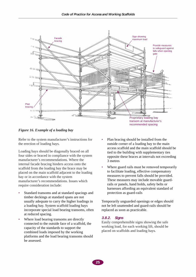
Refer to the system manufacturer’s instructions forthe erection of loading bays.
Loading bays should be diagonally braced on allfour sides or braced in compliance with the systemmanufacturer’s recommendations. Where theinternal facade bracing hinders access onto thescaffold from the loading bay the brace may beplaced on the main scaffold adjacent to the loadingbay or in accordance with the systemmanufacturer’s recommendations. Issues whichrequire consideration include:
• Standard transoms and at standard spacings andtimber deckings at standard spans are notusually adequate to carry the higher loadings ina loading bay. System scaffold loading baysincorporate special load bearing transoms, oftenat reduced spacing.
• Where load bearing transoms are directlyconnected to the outside face of a scaffold, thecapacity of the standards to support thecombined loads imposed by the workingplatforms and the load bearing transoms shouldbe assessed.
• Plan bracing should be installed from theoutside corner of a loading bay to the mainaccess scaffold and the main scaffold should betied to the building with supplementary tiesopposite these braces at intervals not exceeding3 metres
• Where guard rails must be removed temporarilyto facilitate loading, effective compensatorymeasures to prevent falls should be provided.These measures may include movable guard-rails or panels, hand holds, safety belts orharnesses affording an equivalent standard ofprotection as guard-rails
Temporarily unguarded openings or edges shouldnot be left unattended and guard-rails should bereplaced as soon as practicable.
3.8.2. SignsEasily comprehensible signs showing the safeworking load, for each working lift, should beplaced on scaffolds and loading bays.
25
Code of Practice for Access and Working Scaffolds
Provide measuresto safeguard againstfalls when openinggate
Sign showingmaximum loadFacade
bracing
Planbracing
Proprietary loading bay transom at manufacturer's recommended spacing
Figure 16. Example of a loading bay
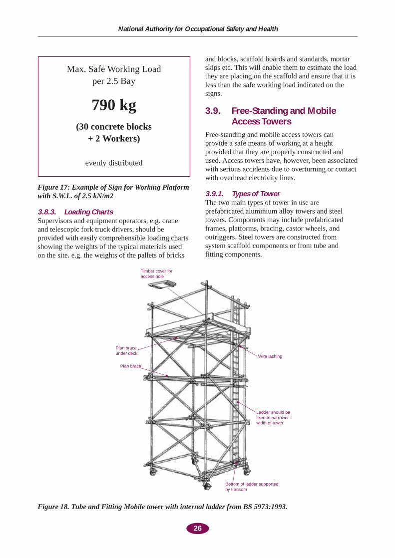
Figure 17: Example of Sign for Working Platformwith S.W.L. of 2.5 kN/m2
3.8.3. Loading ChartsSupervisors and equipment operators, e.g. craneand telescopic fork truck drivers, should beprovided with easily comprehensible loading chartsshowing the weights of the typical materials usedon the site. e.g. the weights of the pallets of bricks
and blocks, scaffold boards and standards, mortarskips etc. This will enable them to estimate the loadthey are placing on the scaffold and ensure that it isless than the safe working load indicated on thesigns.
3.9. Free-Standing and MobileAccess Towers
Free-standing and mobile access towers canprovide a safe means of working at a heightprovided that they are properly constructed andused. Access towers have, however, been associatedwith serious accidents due to overturning or contactwith overhead electricity lines.
3.9.1. Types of TowerThe two main types of tower in use areprefabricated aluminium alloy towers and steeltowers. Components may include prefabricatedframes, platforms, bracing, castor wheels, andoutriggers. Steel towers are constructed fromsystem scaffold components or from tube andfitting components.
26
National Authority for Occupational Safety and Health
Max. Safe Working Load per 2.5 Bay
790 kg(30 concrete blocks
+ 2 Workers)
evenly distributed
Timber cover foraccess hole
Plan braceunder deck
Plan brace
Wire lashing
Ladder should befixed to narrowerwidth of tower
Bottom of ladder supportedby transom
Figure 18. Tube and Fitting Mobile tower with internal ladder from BS 5973:1993.
HD 1004 (BS 1139 Part 3: 1994) gives guidance onstandard mobile prefabricated towers not exceeding8 metres platform height when used externally or12 metres when used internally.
3.9.2. Manufacturer’s InstructionsThe manufacturers and suppliers of prefabricatedand system tower scaffolds should provideinstructions for the erection and use of the scaffold.These instructions should be available to personserecting and using these scaffolds and they shouldbe followed.
3.9.3. StabilityThe conditions of use of the tower andenvironmental forces such as wind can adverselyaffect tower stability. Where the conditions of useor the wind forces are likely to be different fromthose covered by the manufacturer’s instructions orthis code, or the tower is erected in a locationexposed to high winds, the overturning forcesshould be calculated by a competent person.Appropriate measures should be taken to ensurethat the tower has a factor of safety againstoverturning of at least 1.5 in any direction. (SeeSection 2.3.2). For example:
• The stability of free-standing towers which arelikely to be exposed to high winds, othersignificant horizontal loads or where loads willbe hoisted outside of the middle third of the basewidth should be evaluated. Where there is adanger of overturning, an adequate safety factoragainst overturning in any direction should beobtained by the provision of stabilisers,outriggers, kentledge, guys or ties to adjoiningstructures as per the designer’s advice.
3.9.4. Ground SurfaceThe ground surface should be suitable for the typeof tower to be used. Where castors are to be usedthe surface should be even and holes, ducts, pits orgratings should be securely fenced or covered.Where the surface is sloping, the tower should beprevented from slipping. Base plates and soleboards should be used where the ground is soft.
3.9.5. BracingPrefabricated towers should be braced in accordancewith the manufacturer’s instructions. Where thetower is constructed of tube and fitting components,it should be adequately braced on all four sides andbe braced in plan at every alternate lift.
3.9.6. CastorsCastors should be fitted with adequate brakes andthey should be securely fixed to each leg of thetower to prevent accidental uncoupling.
3.9.7. Working PlatformThe deck units or boards should be securely fixedto the frame. Toe-boards and guard-rails should beprovided. The platform should not be over-loaded.
3.9.8. Tower AccessAccess should be provided to the tower by usingvertical or integral ladders, inclined internal laddersor stairways erected in accordance with themanufacturers’ directions. Ladders should beattached to the shorter side of rectangular towersand within the base area of the tower. Externalladders should not be used with aluminium towers.Access to the platforms should be through a hatchwhich is capable of being closed and secured.
3.9.9. Overhead Electricity LinesMobile access towers should not be used adjacentto overhead power lines. Where mobile accesstowers are being used in the same general area asoverhead electricity lines, physical barriers andwarning notices should be provided to prevent themcoming close to the lines.
3.9.10. Instruction, Training and SupervisionPrefabricated towers such as aluminium alloytowers may only be erected by workers withadequate skills and training. Workers should beprovided with adequate and comprehensibleinstructions both for the erection and checking ofthe tower. Competent supervision should beprovided to ensure that towers are safely erected,checked and used.
The training for operatives erecting pre-fabricatedtowers should be appropriate to the work to beperformed. Such training should include:
• Inspection and identification of components• Systems should not be mixed• Safe erection, dismantling and use• Ground conditions• Proximity hazards• Bracing and ties• Least height to base ratios• Use of stabilisers• Moving the tower• Guard-rails and toe-boards• Safe working loads
27
Code of Practice for Access and Working Scaffolds
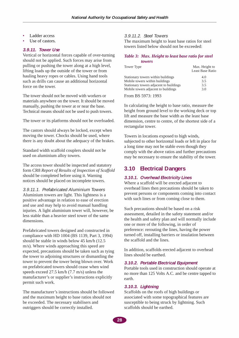
• Ladder access • Use of castors.
3.9.11. Tower Use Vertical or horizontal forces capable of over-turningshould not be applied. Such forces may arise frompulling or pushing the tower along at a high level,lifting loads up the outside of the tower or fromhauling heavy ropes or cables. Using hand toolssuch as drills can cause an additional horizontalforce on the tower.
The tower should not be moved with workers ormaterials anywhere on the tower. It should be movedmanually, pushing the tower at or near the base.Technical means should not be used to push towers.
The tower or its platforms should not be overloaded.
The castors should always be locked, except whenmoving the tower. Chocks should be used, wherethere is any doubt about the adequacy of the brakes.
Standard width scaffold couplers should not beused on aluminium alloy towers.
The access tower should be inspected and statutoryform CR8 Report of Results of Inspection of Scaffoldshould be completed before using it. Warningnotices should be placed on incomplete towers.
3.9.11.1. Prefabricated Aluminium TowersAluminium towers are light. This lightness is apositive advantage in relation to ease of erectionand use and may help to avoid manual handlinginjuries. A light aluminium tower will, however, beless stable than a heavier steel tower of the samedimensions.
Prefabricated towers designed and constructed incompliance with HD 1004 (BS 1139, Part 3, 1994)should be stable in winds below 45 km/h (12.5m/s). Where winds approaching this speed areexpected, precautions should be taken such as tyingthe tower to adjoining structures or dismantling thetower to prevent the tower being blown over. Workon prefabricated towers should cease when windspeeds exceed 27.5 km/h (7.7 m/s) unless themanufacturer’s or supplier’s instructions explicitlypermit such work.
The manufacturer’s instructions should be followedand the maximum height to base ratios should notbe exceeded. The necessary stabilisers andoutriggers should be correctly installed.
3.9.11.2. Steel TowersThe maximum height to least base ratios for steeltowers listed below should not be exceeded:
Table 3: Max. Height to least base ratio for steeltowers
Tower Type Max. Height to Least Base Ratio
Stationary towers within buildings 4.0Mobile towers within buildings 3.5Stationary towers adjacent to buildings 3.5Mobile towers adjacent to buildings 3.0
From BS 5973: 1993
In calculating the height to base ratio, measure theheight from ground level to the working deck or toplift and measure the base width as the least basedimension, centre to centre, of the shortest side of arectangular tower.
Towers in locations exposed to high winds,subjected to other horizontal loads or left in place fora long time may not be stable even though theycomply with the above ratios and further precautionsmay be necessary to ensure the stability of the tower.
3.10 Electrical Dangers
3.10.1. Overhead Electricity LinesWhere a scaffold will be erected adjacent tooverhead lines then precautions should be taken toprevent persons or components coming into contactwith such lines or from coming close to them.
Such precautions should be based on a riskassessment, detailed in the safety statement and/orthe health and safety plan and will normally includeone or more of the following, in order ofpreference: rerouting the lines, having the powerturned off, installing barriers or insulation betweenthe scaffold and the lines.
In addition, scaffolds erected adjacent to overheadlines should be earthed.
3.10.2. Portable Electrical EquipmentPortable tools used in construction should operate atno more than 125 Volts A.C. and be centre tapped toearth.
3.10.3. LightningScaffolds on the roofs of high buildings orassociated with some topographical features aresusceptible to being struck by lightning. Suchscaffolds should be earthed.
28
National Authority for Occupational Safety and Health
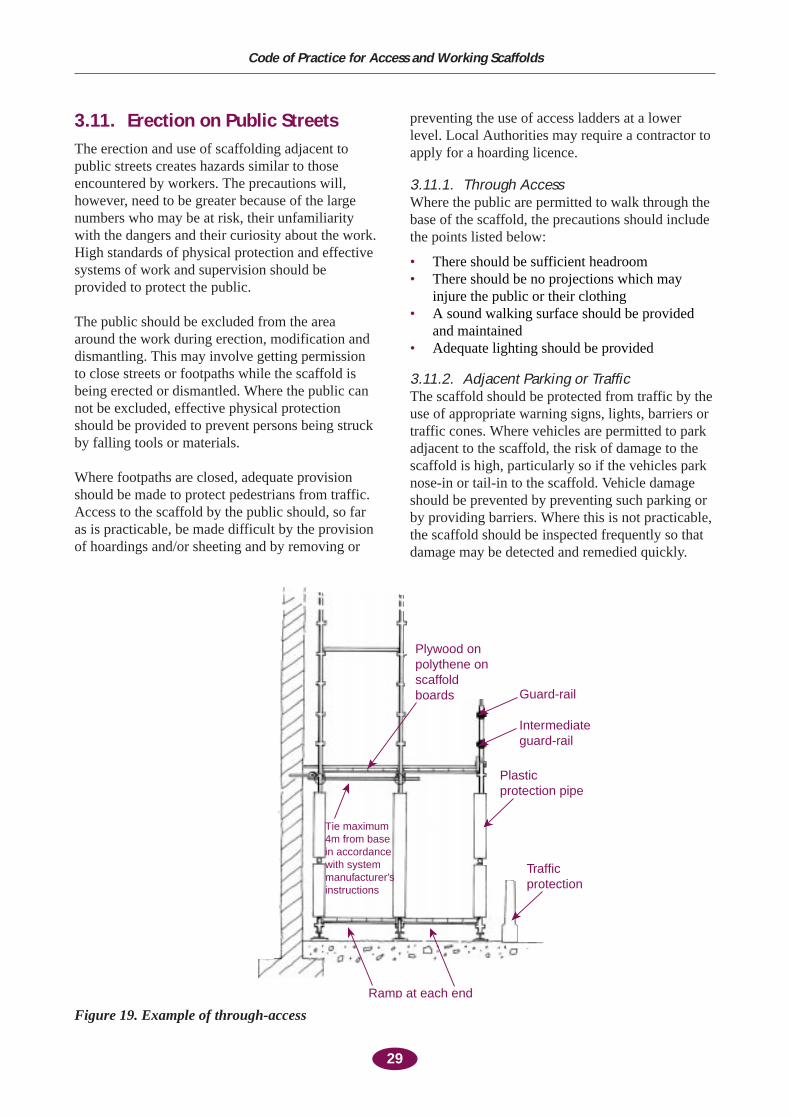
3.11. Erection on Public StreetsThe erection and use of scaffolding adjacent topublic streets creates hazards similar to thoseencountered by workers. The precautions will,however, need to be greater because of the largenumbers who may be at risk, their unfamiliaritywith the dangers and their curiosity about the work.High standards of physical protection and effectivesystems of work and supervision should beprovided to protect the public.
The public should be excluded from the areaaround the work during erection, modification anddismantling. This may involve getting permissionto close streets or footpaths while the scaffold isbeing erected or dismantled. Where the public cannot be excluded, effective physical protectionshould be provided to prevent persons being struckby falling tools or materials.
Where footpaths are closed, adequate provisionshould be made to protect pedestrians from traffic.Access to the scaffold by the public should, so faras is practicable, be made difficult by the provisionof hoardings and/or sheeting and by removing or
preventing the use of access ladders at a lowerlevel. Local Authorities may require a contractor toapply for a hoarding licence.
3.11.1. Through AccessWhere the public are permitted to walk through thebase of the scaffold, the precautions should includethe points listed below:
• There should be sufficient headroom• There should be no projections which may
injure the public or their clothing• A sound walking surface should be provided
and maintained • Adequate lighting should be provided
3.11.2. Adjacent Parking or TrafficThe scaffold should be protected from traffic by theuse of appropriate warning signs, lights, barriers ortraffic cones. Where vehicles are permitted to parkadjacent to the scaffold, the risk of damage to thescaffold is high, particularly so if the vehicles parknose-in or tail-in to the scaffold. Vehicle damageshould be prevented by preventing such parking orby providing barriers. Where this is not practicable,the scaffold should be inspected frequently so thatdamage may be detected and remedied quickly.
29
Code of Practice for Access and Working Scaffolds
Ramp at each end
Tie maximum 4m from base in accordance with system manufacturer’sinstructions
Trafficprotection
Plasticprotection pipe
Intermediateguard-rail
Guard-rail
Plywood onpolythene onscaffoldboards
Figure 19. Example of through-access
An adequate hand-over procedure for transferringcontrol of the scaffold from the erector to the user isan important part of managing scaffold safety. Boththe scaffold erector and the user should be satisfiedthat the scaffold can provide a safe workingplatform and can carry the imposed loads safely. Anadequate hand-over procedure will include thepoints listed below:
• The areas of the scaffold which have beenhanded over should be clearly identified
• The maximum capacity of the loading bays andworking platforms and the tie spacing should beclearly stated
• The entire area of the scaffold should beinspected before it is taken into use. Thescaffold inspection checklist given in Appendix B on page 41 or another suitablechecklist may be used
• “Scaffold incomplete” warning notices shouldbe removed from the finished scaffold
• A report of the inspection should be made onForm CR8 Report of Results of Inspection of:Scaffold and a copy of the report should beretained on site
• The person responsible for furthermodifications and inspections of the scaffoldshould be identified.
30
National Authority for Occupational Safety and Health
4. Inspection and Hand-Over
5.1. Scaffold UsersA scaffold should not to be used unless it isproperly constructed and is suitable for the purposefor which it is required, has been inspected andform CR8 Report of Inspection has been completed.
Each contractor (including sub-contractors and theself-employed) should satisfy himself (personally orthrough a servant or agent) that the scaffold isstable, that the materials used in its construction aresound and that it is safe to use. Each contractorshould satisfy himself that the scaffold has beeninspected by a competent person and that form CR8Report of Inspection has been completed before use.
Users (including contractors and workers) should:• Be provided with relevant information on the
conditions of use of the scaffold, including theloading capacity of the scaffold, in acomprehensible form
• Not overload the scaffold either locally or ingeneral
• Not interfere with or misuse the scaffold• Promptly report defects in the scaffold to
whoever is in control of the scaffold• Not leave a scaffold in a hazardous condition
for current or subsequent users
5.2. ModificationUncontrolled modification of a scaffold,particularly if carried out by persons withoutadequate competence, can lead to instability and anincreased risk of persons falling from the scaffold.Modifications to ties, bracing, ledgers, transomsand decking should be identified, requested andmade in good time. (See 2.5)
Only competent persons who have been trained andare experienced in the kind of work may makemodifications to scaffolds.
A sufficient number of competent scaffoldersshould be available to ensure that modifications aremade in good time
Guard-rails and toe boards in a single bay may betemporarily removed by persons who have beenappropriately instructed in the safe means ofremoving and replacing the guard-rail. They shouldbe instructed in the legal requirement to remain inattendance at the location of the removed guard-railor toe-board until it has been replaced.
5.3. MaintenanceThe scaffold should be maintained in a safecondition for the entire period of its use. See 2.5Planning for Use and Maintenance
5.4. Inspection Before and DuringUse
Scaffolds should be inspected before use and atleast every seven days and after any circumstancethat might affect the stability or safety of thescaffold. Such circumstances include:
• Modification• Period without use• Exposure to bad weather• Damage, including impact of traffic or site
equipment with the scaffold
The scaffold inspection checklist given in AppendixB or another suitable checklist may be used. Areport of the inspection should be made on FormCR8 Report of Results of Inspection of: Scaffoldand a copy of the report should be retained on site.
31
Code of Practice for Access and Working Scaffolds
5. Use, Modification and Maintenance
Dismantling a scaffold can place large loads on thescaffold unless the work is planned to keep theamount of material stored on the scaffold to aminimum. The work should be planned so that thescaffold will not become unstable, workers areprevented from falling from the scaffold and othersare protected from the risk of falling materials.
6.1. StabilityThe scaffold should be examined to ensure that thefoundation is adequate and that all ties and bracesare in position and are effective
Any defects found in the scaffold should be madegood before commencing dismantling
The dismantling should be planned so that stabilityis assured by providing adequate bracing and tiesand by restricting the imposed loads due to stackedscaffold components.
Where the scaffold must be used to temporarilystore large amounts of components, it should bestrengthened and stabilised, e.g by providing extrastandards, ties or rakers
Prominent warning notices should be placed andaccess to the danger zone should be prevented
6.2 Protection from FallsWorkers should be protected from falling duringdismantling of scaffolding. (See Section 3.1)
6.3. Protection from FallingObjects
Workers and members of the public should beprotected from the risk of being struck by fallingscaffold components. (See Section 3.6.)
32
National Authority for Occupational Safety and Health
6. Dismantling
The risks associated with the erection, use anddismantling of scaffolding are potentially very high.Persons given the task of erecting, altering, using ordismantling scaffolding should have the necessarycompetence to perform their tasks safely.
7.1. Competence of ScaffoldersA scaffold should not be erected, substantiallyadded to, altered or dismantled unless it isperformed:
• Under the immediate supervision of acompetent person, and
• By persons trained and experienced in the kindof work
A competent person is a person who has been fullytrained, has acquired the necessary knowledge andpractical experience and has received the necessaryinstructions for the erection, alteration ordismantling of the type of scaffold.
7.1.1. TrainingFormal training is required for those who erect,substantially add to, alter or dismantle a scaffold.The training should include training on any risksinvolved. The extent of training required willdepend on the type of work normally undertakenand on the type of scaffold. The minimumacceptable standard of training is the approved FÁSConstruction Skills Certification Scheme forscaffolders, or an equivalent training programmeaccredited by FÁS.
7.1.2. ExperienceA competent and experienced person shouldsupervise the erection, alteration or dismantling of ascaffold. The person should be experienced in thekind of work being undertaken.
7.1.3. Assessment, Certification andRegistration
In order to help employers, contractors and projectsupervisors determine whether scaffolders have thenecessary competence to erect or dismantlescaffolding, FÁS have introduced a programme toassess scaffolders’ competence, to issue certificatesto those with the necessary skills and to keep aregister of qualified scaffolders.
Employers, contractors and project supervisors forthe construction stage should satisfy themselvesthat persons erecting scaffolding have the necessarytraining by seeking evidence of FÁS certification oran equivalent certification accredited by FÁS.
7.2. Competence for InspectionThe designated person inspecting a scaffold shouldbe competent. A competent person is a person whois fully trained, has acquired the necessaryknowledge and practical experience and hasreceived the necessary instructions for theinspection of the type of scaffold.
7.2.1. Training for InspectionWhile it is relatively easy to inspect for certaindefects such as missing guard-rails, an untrainedperson may not be able to form an opinion on thestability of the scaffold.
Those performing simple scaffold inspectionsshould have received at least one day of formaltraining in scaffold inspection and be competent.Extra training would be required for the inspectionof complex scaffolds.
Employers, contractors and project supervisorsshould seek evidence of appropriate certification oftraining in order to verify that training has beenreceived. Periodic refresher training should beprovided where appropriate.
7.3. Training and Instruction forScaffold Users
All scaffold users should receive training andinstruction in the use of the scaffold. It is importantto provide this training and instruction because theusers may not otherwise realise when they are atrisk, may not request modifications in time and mayinterfere with the scaffold, putting themselves andothers at risk.
This training may be provided as part of theinduction which all persons who are likely to usethe scaffold, either as access or as a workingplatform, should receive.
33
Code of Practice for Access and Working Scaffolds
7. Competence
7.3.1. Contents of InductionThe induction of scaffold users should cover at leastthe areas listed below:
• Users should be able to recognise when ascaffold is complete, e.g. full boarding, guard-rails and toe-boards present.
• The meaning of warning signs or scaffoldtagging systems in use.
• That users should not interfere or makemodifications to scaffolding. Modificationsmay only be made by a competent person withthe appropriate training and certification.
• The maximum loading capacity of the scaffoldworking platforms and loading towers,illustrated with specific comprehensibleexamples relating to the materials in use on thesite.
• That users should report defects to a designatedperson.
• That materials should not be thrown fromscaffold.
• That users should use the designated accesspoints and should not climb the scaffold.
7.4. Training and Instruction ofEquipment Operators
The mechanical placing of materials on a scaffoldcan give rise to significant impact loads andoverloading of the scaffold can provoke a generalcollapse of the scaffold.
Equipment operators such as crane drivers andtelescopic fork-truck drivers as well as signallers(banksmen) should be competent, have receivedtraining and assessment and received certification.FÁS provides training courses for equipmentoperators and assesses, certifies and registers trainedoperators. Other appropriately qualified bodies mayapply to FÁS for accreditation of courses.
Lifting equipment operators should be informed ofthe safe working load of the scaffold workingplatforms and loading bays. Comprehensibleexamples relating to the materials in use on the siteshould be provided. It may be necessary to reviewthe information provided as the materials orscaffold lay-out changes.
Excavation close to the scaffold can undermine it.Excavator operators should be informed of theminimum distances that they should observe whenexcavating in the vicinity of the scaffold
34
National Authority for Occupational Safety and Health
35
Appendix A
Tube and Fitting Scaffolds
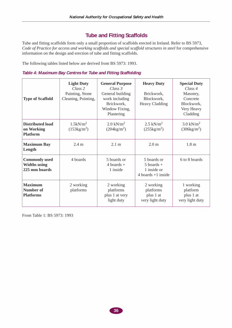
36
National Authority for Occupational Safety and Health
Tube and Fitting ScaffoldsTube and fitting scaffolds form only a small proportion of scaffolds erected in Ireland. Refer to BS 5973,Code of Practice for access and working scaffolds and special scaffold structures in steel for comprehensiveinformation on the design and erection of tube and fitting scaffolds.
The following tables listed below are derived from BS 5973: 1993.
Table 4: Maximum Bay Centres for Tube and Fitting Scaffolding
Light Duty General Purpose Heavy Duty Special DutyClass 2 Class 3 Class 4
Painting, Stone General building Brickwork, Masonry, Type of Scaffold Cleaning, Pointing, work including Blockwork, Concrete
Brickwork, Heavy Cladding Blockwork, Window Fixing, Very Heavy
Plastering Cladding
Distributed load 1.5kN/m2 2.0 kN/m2 2.5 kN/m2 3.0 kN/m2
on Working (153kg/m2) (204kg/m2) (255kg/m2) (306kg/m2)Platform
Maximum Bay 2.4 m 2.1 m 2.0 m 1.8 mLength
Commonly used 4 boards 5 boards or 5 boards or 6 to 8 boardsWidths using 4 boards + 5 boards +225 mm boards 1 inside 1 inside or
4 boards +1 inside
Maximum 2 working 2 working 2 working 1 working Number of platforms platforms platforms platform Platforms plus 1 at very plus 1 at plus 1 at
light duty very light duty very light duty
From Table 1: BS 5973: 1993
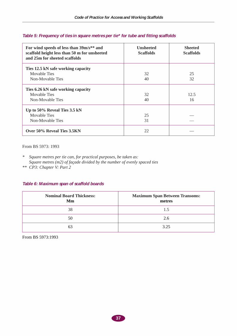
37
Code of Practice for Access and Working Scaffolds
Table 5: Frequency of ties in square metres per tie* for tube and fitting scaffolds
For wind speeds of less than 39m/s** and Unsheeted Sheetedscaffold height less than 50 m for unsheeted Scaffolds Scaffoldsand 25m for sheeted scaffolds
Ties 12.5 kN safe working capacityMovable Ties 32 25Non-Movable Ties 40 32
Ties 6.26 kN safe working capacityMovable Ties 32 12.5Non-Movable Ties 40 16
Up to 50% Reveal Ties 3.5 kNMovable Ties 25 —Non-Movable Ties 31 —
Over 50% Reveal Ties 3.5KN 22 —
From BS 5973: 1993
* Square metres per tie can, for practical purposes, be taken as:Square metres (m2) of façade divided by the number of evenly spaced ties
** CP3: Chapter V: Part 2
Table 6: Maximum span of scaffold boards
Nominal Board Thickness: Maximum Span Between Transoms:Mm metres
38 1.5
50 2.6
63 3.25
From BS 5973:1993

38
Appendix B
Example Check-Lists
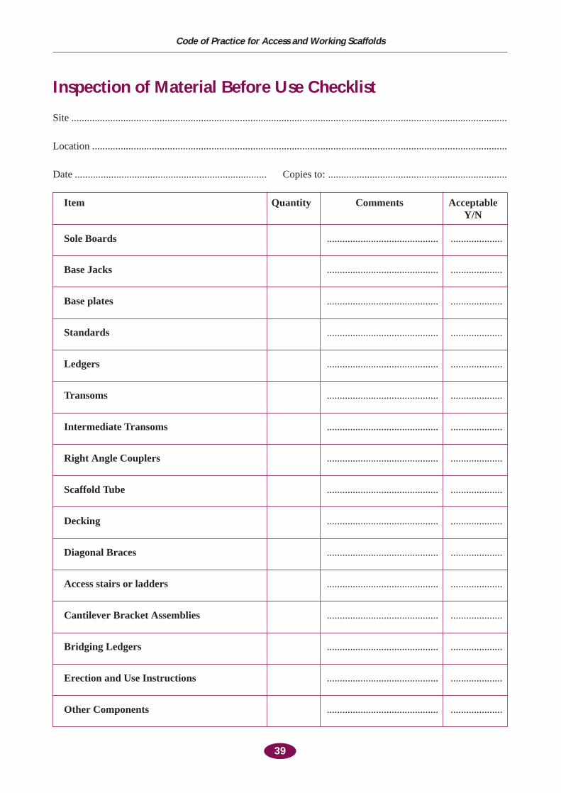
39
Code of Practice for Access and Working Scaffolds
Inspection of Material Before Use Checklist
Site ........................................................................................................................................................................
Location ................................................................................................................................................................
Date .......................................................................... Copies to: .....................................................................
Item Quantity Comments Acceptable Y/N
Sole Boards ........................................... ....................
Base Jacks ........................................... ....................
Base plates ........................................... ....................
Standards ........................................... ....................
Ledgers ........................................... ....................
Transoms ........................................... ....................
Intermediate Transoms ........................................... ....................
Right Angle Couplers ........................................... ....................
Scaffold Tube ........................................... ....................
Decking ........................................... ....................
Diagonal Braces ........................................... ....................
Access stairs or ladders ........................................... ....................
Cantilever Bracket Assemblies ........................................... ....................
Bridging Ledgers ........................................... ....................
Erection and Use Instructions ........................................... ....................
Other Components ........................................... ....................

40
National Authority for Occupational Safety and Health
Scaffold Hand-Over Form
Site ........................................................................................................................................................................
Location ................................................................................................................................................................
Date .......................................................................... Copies to: .....................................................................
Signed
Erector ...................................................................... User ..............................................................................
Before using a scaffold the scaffold should be inspected and form CR8 should be completed
A scaffold may be inspected by a person who is competent, this may include a trained scaffolder or anotherperson who has been trained in scaffold inspection
Area Of Scaffold Handed Over ....................................................................................(Identify using grid-lines)
....................................................................................
Maximum Loading Capacity Of Working ....................................................................................Platforms (in kg/bay or for non-standard bays in kg/m2) ....................................................................................
Maximum Number Of Platforms To ....................................................................................Be Loaded ....................................................................................
Scaffold Inspection Performed Yes ■■ No ■■
CR8 Report Of Inspection Signed Yes ■■ No ■■
Person Responsible For Making ....................................................................................Periodic Inspections....................................................................................
Person Responsible For Authorising ....................................................................................Modifications, e.g. Site Agent, Foreman,
Scaffolder ....................................................................................
Necessary Design Information To ....................................................................................Enable Inspections To Be PerformedE.G. Tie Spacing, Plan or Ledger Bracing Etc. ....................................................................................
....................................................................................
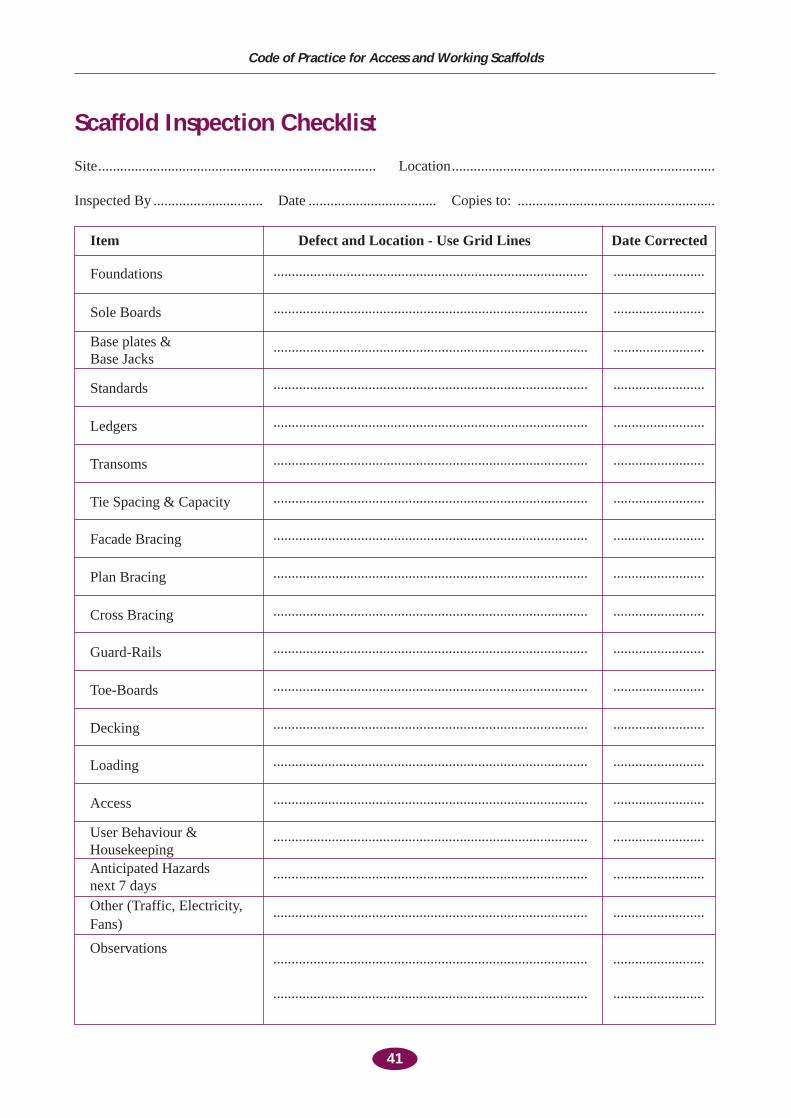
41
Code of Practice for Access and Working Scaffolds
Scaffold Inspection Checklist
Site............................................................................ Location........................................................................
Inspected By .............................. Date ................................... Copies to: ......................................................
Item Defect and Location - Use Grid Lines Date Corrected
Foundations ...................................................................................... .........................
Sole Boards ...................................................................................... .........................
Base plates &Base Jacks
...................................................................................... .........................
Standards ...................................................................................... .........................
Ledgers ...................................................................................... .........................
Transoms ...................................................................................... .........................
Tie Spacing & Capacity ...................................................................................... .........................
Facade Bracing ...................................................................................... .........................
Plan Bracing ...................................................................................... .........................
Cross Bracing ...................................................................................... .........................
Guard-Rails ...................................................................................... .........................
Toe-Boards ...................................................................................... .........................
Decking ...................................................................................... .........................
Loading ...................................................................................... .........................
Access ...................................................................................... .........................
User Behaviour & ...................................................................................... .........................HousekeepingAnticipated Hazards ...................................................................................... .........................next 7 daysOther (Traffic, Electricity, ...................................................................................... .........................Fans)
Observations...................................................................................... .........................
...................................................................................... .........................

42
Appendix C
Form CR8 Report of Results of Inspection of: Scaffold

43
Code of Practice for Access and Working Scaffolds
The Safety, Health and Welfare at Work (Construction) Regulations, 1995S.I. No. 138 of 1995, Form CR8
Report of results of inspection of : SCAFFOLDS[Approved by the National Authority for Occupational Safety and Health in accordance with Regulation65(1)(d)]
Name or title of Employer or Contractor#:
Address of Registered Office,Head Office, or Site:
# i.e. the person for whom the Report has been prepared (See notes on next page)
Location and Description Date of Result of Inspection Signature of person of Scaffold and other Plant or Inspection State whether who made
Equipment Inspected in good order the inspection
(1) (2) (3) (4)
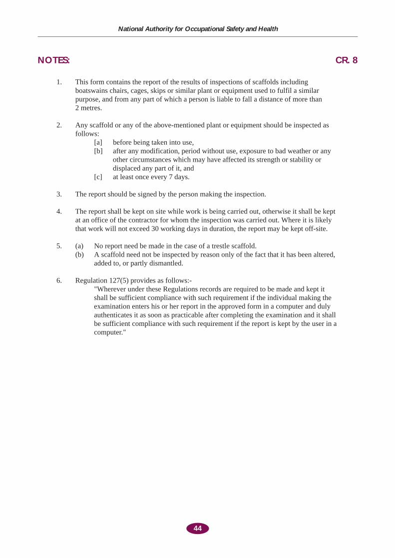
44
National Authority for Occupational Safety and Health
NOTES: CR. 8
1. This form contains the report of the results of inspections of scaffolds includingboatswains chairs, cages, skips or similar plant or equipment used to fulfil a similarpurpose, and from any part of which a person is liable to fall a distance of more than 2 metres.
2. Any scaffold or any of the above-mentioned plant or equipment should be inspected asfollows:
[a] before being taken into use,[b] after any modification, period without use, exposure to bad weather or any
other circumstances which may have affected its strength or stability ordisplaced any part of it, and
[c] at least once every 7 days.
3. The report should be signed by the person making the inspection.
4. The report shall be kept on site while work is being carried out, otherwise it shall be keptat an office of the contractor for whom the inspection was carried out. Where it is likelythat work will not exceed 30 working days in duration, the report may be kept off-site.
5. (a) No report need be made in the case of a trestle scaffold.(b) A scaffold need not be inspected by reason only of the fact that it has been altered,
added to, or partly dismantled.
6. Regulation 127(5) provides as follows:-"Wherever under these Regulations records are required to be made and kept itshall be sufficient compliance with such requirement if the individual making theexamination enters his or her report in the approved form in a computer and dulyauthenticates it as soon as practicable after completing the examination and it shallbe sufficient compliance with such requirement if the report is kept by the user in acomputer."

45
Appendix D
Weights of Typical Building Materials
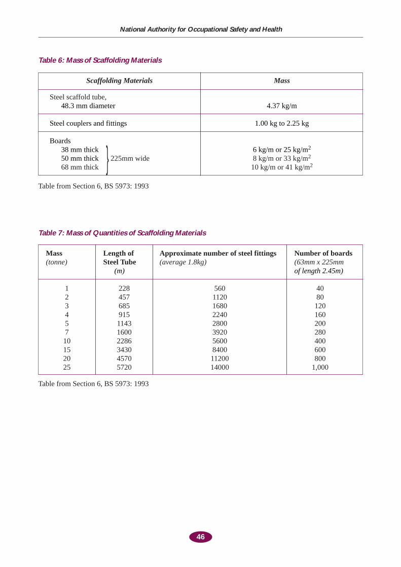
46
National Authority for Occupational Safety and Health
Table 6: Mass of Scaffolding Materials
Scaffolding Materials Mass
Steel scaffold tube,48.3 mm diameter 4.37 kg/m
Steel couplers and fittings 1.00 kg to 2.25 kg
Boards38 mm thick 6 kg/m or 25 kg/m2
50 mm thick } 225mm wide 8 kg/m or 33 kg/m2
68 mm thick 10 kg/m or 41 kg/m2
Table from Section 6, BS 5973: 1993
Table 7: Mass of Quantities of Scaffolding Materials
Mass Length of Approximate number of steel fittings Number of boards (tonne) Steel Tube (average 1.8kg) (63mm x 225mm
(m) of length 2.45m)
1 228 560 402 457 1120 803 685 1680 1204 915 2240 1605 1143 2800 2007 1600 3920 28010 2286 5600 40015 3430 8400 60020 4570 11200 80025 5720 14000 1,000
Table from Section 6, BS 5973: 1993
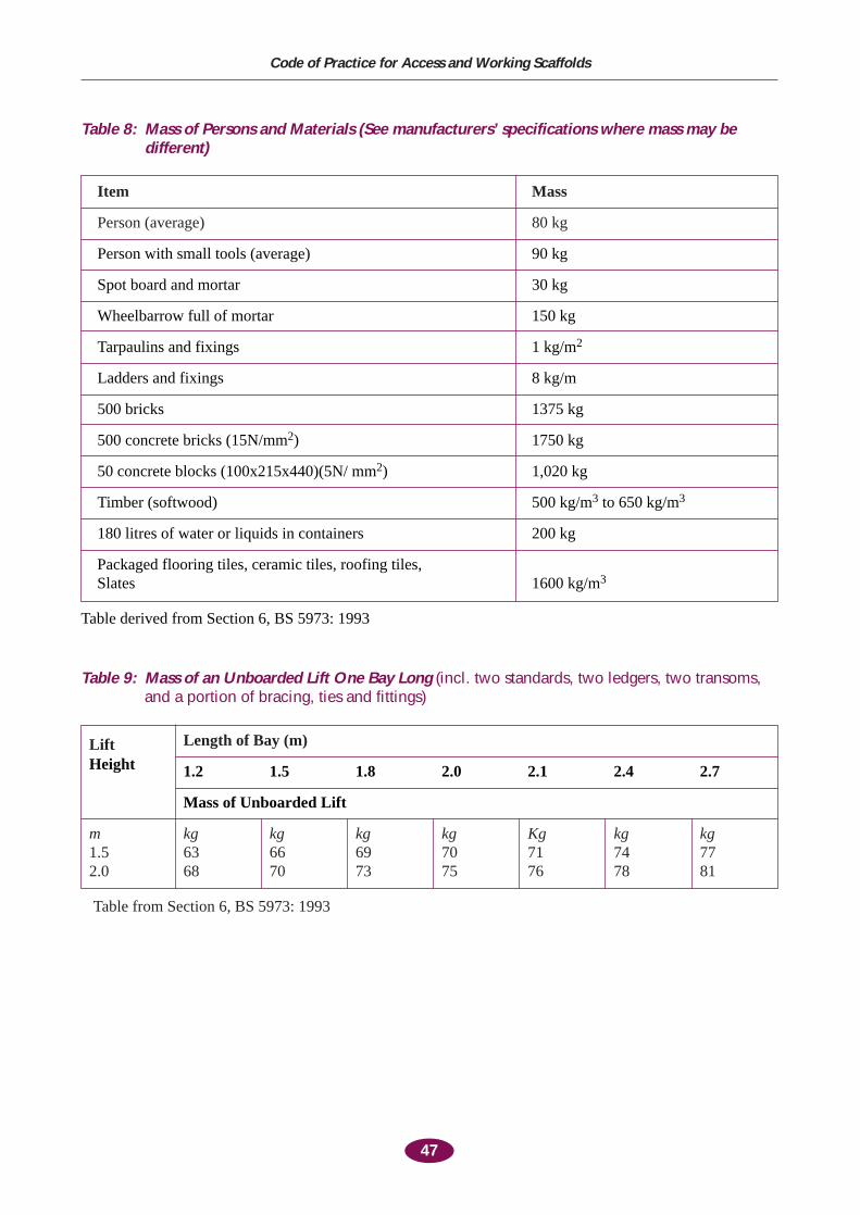
47
Code of Practice for Access and Working Scaffolds
Table 8: Mass of Persons and Materials (See manufacturers’ specifications where mass may bedifferent)
Item Mass
Person (average) 80 kg
Person with small tools (average) 90 kg
Spot board and mortar 30 kg
Wheelbarrow full of mortar 150 kg
Tarpaulins and fixings 1 kg/m2
Ladders and fixings 8 kg/m
500 bricks 1375 kg
500 concrete bricks (15N/mm2) 1750 kg
50 concrete blocks (100x215x440)(5N/ mm2) 1,020 kg
Timber (softwood) 500 kg/m3 to 650 kg/m3
180 litres of water or liquids in containers 200 kg
Packaged flooring tiles, ceramic tiles, roofing tiles, Slates 1600 kg/m3
Table derived from Section 6, BS 5973: 1993
Table 9: Mass of an Unboarded Lift One Bay Long (incl. two standards, two ledgers, two transoms,and a portion of bracing, ties and fittings)
Lift Length of Bay (m)
Height 1.2 1.5 1.8 2.0 2.1 2.4 2.7
Mass of Unboarded Lift
m kg kg kg kg Kg kg kg1.5 63 66 69 70 71 74 772.0 68 70 73 75 76 78 81
Table from Section 6, BS 5973: 1993

48
Appendix E
Information Sources
49
Code of Practice for Access and Working Scaffolds
Statutory ProvisionsSafety Health and Welfare at Work Act, 1989Safety Health and Welfare at Work (General Application) Regulations, 1993Safety Health and Welfare at Work (Construction) Regulations, 1995
Irish StandardsIS/EN74: 1989 Couplers, loose spigots, and base plates for use in working scaffolds and
falsework made of steelIS 745: 1989 Machine graded home grown timber scaffold boardsIS/HD 1000:1989 Service and working scaffolds made of prefabricated elementsIS/HD 1039 Steel tubes for falsework and working scaffolds. Requirements. Tests
British Standards, Codes and Other StandardsBS 1139: Metal scaffolding, Parts 1 to 5 (HD 1000 Harmonisation Document Service and
Working Scaffolds made of prefabricated elements)BS 5973: Code of practice for access and working scaffolds in steelBS 5974: Codes of practice for temporarily installed suspended scaffolds and access
equipmentISO 4054 Scaffold couplersEN 39 and EN 244: Steel tubesBS 6399: Part 3, CP for imposed snow loads CP 3: Code of basic data for the design of buildings
Chapter V LoadingPart 2 Wind loads
BS 6399: Loading for buildingsPart I Code of practice for dead and imposed loadsPart 3 Code of practice for imposed roof loads
BS 4074: Metal props and strutsBS 1397: Industrial safety belts and harnessesBS 2830: Cradles and safety chairsBS 8093: Code of practice for the use of safety nets, containment nets and sheets on
constructional worksBS CP93: Safety netsBS 3913: Specification of industrial safety netsBS 2095 and BS 2826: Light and heavy-duty safety helmetsBS 449: Parts 1, 2 and 4 amendments: Structural steelBS 5507: Part 3, Falsework equipmentBS 5975: FalseworkBS 302: Wire ropes for cranes and general engineering purposesBS 4978: Timber grades for structural useBS 1129: Timber ladder steps, trestles and lightweight stagingsBS 648: Schedule of weights of building materialsBS 2482: Specification for timber scaffold boardsBS 5268: Structural use of timberBS 6180: Code of practice for protective barriers in and about buildingsBS 4848: Specification for hot rolled structural steel sections
Part 2 Hollow sections
50
National Authority for Occupational Safety and Health
Health and Safety Authority Guidance Guidelines to the Safety Health and Welfare at Work (Construction) Regulations, 1995Guidelines on Preparing Your Safety StatementWorkplace Heath and Safety Management – Practical GuidelinesBuild in Safety – A Short Guide to Good Practice and LegislationStay Safe on SiteScaffolding Safety Video
Health and Safety Executive (UK) Guidance NotesHSG 10: Safety in RoofworkGS 15: General access scaffoldsGS 42: Tower scaffoldsGS 28/3: Safe erection, Part 3: Working places and accessGS 31: Safe use of ladders, step-ladders and trestlesGS 25: Prevention of falls by window cleaners
TextbooksWind Loading Handbook : Newberry and Eaton : BRE : HMSOThe Assessment of Wind Loads : BRE Digest 346, Parts 1 to 7 : HMSOWind Loads on Canopy Roofs : BRE Digest 284 : HMSOWind Environment around Tall Buildings : BRE Digest 141 : HMSOWind Forces on Unclad Tubular Structures : Constrado Publication 1/75Access Scaffolding. S. Champion. Longman Group
OrganisationsHealth and Safety Authority, 10 Hogan Place, Dublin 2, (01) 614 7000FÁS, Ballyfermot, Dublin 10National Association of Scaffolding Contractors: Construction House, Canal Road, Dublin 6.
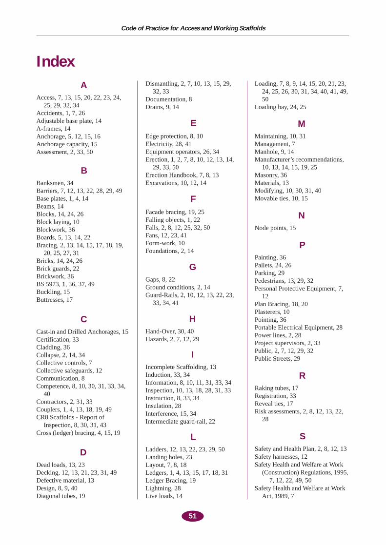
51
Code of Practice for Access and Working Scaffolds
AAccess, 7, 13, 15, 20, 22, 23, 24,
25, 29, 32, 34Accidents, 1, 7, 26Adjustable base plate, 14A-frames, 14Anchorage, 5, 12, 15, 16Anchorage capacity, 15Assessment, 2, 33, 50
BBanksmen, 34Barriers, 7, 12, 13, 22, 28, 29, 49Base plates, 1, 4, 14Beams, 14Blocks, 14, 24, 26Block laying, 10Blockwork, 36Boards, 5, 13, 14, 22Bracing, 2, 13, 14, 15, 17, 18, 19,
20, 25, 27, 31Bricks, 14, 24, 26Brick guards, 22Brickwork, 36BS 5973, 1, 36, 37, 49Buckling, 15Buttresses, 17
CCast-in and Drilled Anchorages, 15Certification, 33Cladding, 36Collapse, 2, 14, 34Collective controls, 7Collective safeguards, 12Communication, 8Competence, 8, 10, 30, 31, 33, 34,
40Contractors, 2, 31, 33Couplers, 1, 4, 13, 18, 19, 49CR8 Scaffolds - Report of
Inspection, 8, 30, 31, 43Cross (ledger) bracing, 4, 15, 19
DDead loads, 13, 23Decking, 12, 13, 21, 23, 31, 49Defective material, 13Design, 8, 9, 40Diagonal tubes, 19
Dismantling, 2, 7, 10, 13, 15, 29,32, 33
Documentation, 8Drains, 9, 14
EEdge protection, 8, 10Electricity, 28, 41Equipment operators, 26, 34Erection, 1, 2, 7, 8, 10, 12, 13, 14,
29, 33, 50Erection Handbook, 7, 8, 13Excavations, 10, 12, 14
FFacade bracing, 19, 25Falling objects, 1, 22Falls, 2, 8, 12, 25, 32, 50Fans, 12, 23, 41Form-work, 10Foundations, 2, 14
GGaps, 8, 22Ground conditions, 2, 14Guard-Rails, 2, 10, 12, 13, 22, 23,
33, 34, 41
HHand-Over, 30, 40Hazards, 2, 7, 12, 29
IIncomplete Scaffolding, 13Induction, 33, 34Information, 8, 10, 11, 31, 33, 34Inspection, 10, 13, 18, 28, 31, 33Instruction, 8, 33, 34Insulation, 28Interference, 15, 34Intermediate guard-rail, 22
LLadders, 12, 13, 22, 23, 29, 50Landing holes, 23Layout, 7, 8, 18Ledgers, 1, 4, 13, 15, 17, 18, 31Ledger Bracing, 19Lightning, 28Live loads, 14
Loading, 7, 8, 9, 14, 15, 20, 21, 23,24, 25, 26, 30, 31, 34, 40, 41, 49,50
Loading bay, 24, 25
MMaintaining, 10, 31Management, 7Manhole, 9, 14Manufacturer’s recommendations,
10, 13, 14, 15, 19, 25Masonry, 36Materials, 13Modifying, 10, 30, 31, 40Movable ties, 10, 15
NNode points, 15
PPainting, 36Pallets, 24, 26Parking, 29Pedestrians, 13, 29, 32Personal Protective Equipment, 7,
12Plan Bracing, 18, 20Plasterers, 10Pointing, 36Portable Electrical Equipment, 28Power lines, 2, 28Project supervisors, 2, 33Public, 2, 7, 12, 29, 32Public Streets, 29
RRaking tubes, 17Registration, 33Reveal ties, 17Risk assessments, 2, 8, 12, 13, 22,
28
SSafety and Health Plan, 2, 8, 12, 13Safety harnesses, 12Safety Health and Welfare at Work
(Construction) Regulations, 1995,7, 12, 22, 49, 50
Safety Health and Welfare at WorkAct, 1989, 7
Index
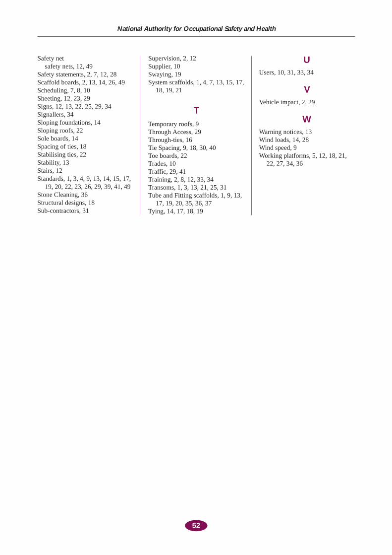
52
National Authority for Occupational Safety and Health
Safety netsafety nets, 12, 49
Safety statements, 2, 7, 12, 28Scaffold boards, 2, 13, 14, 26, 49Scheduling, 7, 8, 10Sheeting, 12, 23, 29Signs, 12, 13, 22, 25, 29, 34Signallers, 34Sloping foundations, 14Sloping roofs, 22Sole boards, 14Spacing of ties, 18Stabilising ties, 22Stability, 13Stairs, 12Standards, 1, 3, 4, 9, 13, 14, 15, 17,
19, 20, 22, 23, 26, 29, 39, 41, 49Stone Cleaning, 36Structural designs, 18Sub-contractors, 31
Supervision, 2, 12Supplier, 10Swaying, 19System scaffolds, 1, 4, 7, 13, 15, 17,
18, 19, 21
TTemporary roofs, 9Through Access, 29Through-ties, 16Tie Spacing, 9, 18, 30, 40Toe boards, 22Trades, 10Traffic, 29, 41Training, 2, 8, 12, 33, 34Transoms, 1, 3, 13, 21, 25, 31Tube and Fitting scaffolds, 1, 9, 13,
17, 19, 20, 35, 36, 37Tying, 14, 17, 18, 19
UUsers, 10, 31, 33, 34
VVehicle impact, 2, 29
WWarning notices, 13Wind loads, 14, 28Wind speed, 9Working platforms, 5, 12, 18, 21,
22, 27, 34, 36