Embed Size (px)
Citation preview
COMANDO E SEGNALAZIONE - FILO PANNELLO SM2 Ø 30
1 032 | www.newelfin.com
2www.newelfin.com | 032
COMANDO E SEGNALAZIONE - FILO PANNELLO SM2 Ø 30
2
032COMANDO E SEGNALAZIONE
FILO PANNELLO SM2 Ø30
COMMAND AND SIGNALLING FLUSH-MOUNT SM2 Ø30
www.newelfin.com | 032
COMANDO E SEGNALAZIONE - FILO PANNELLO SM2 Ø 30
3 032 | www.newelfin.com
LA SERIE 032
La serie 032 '''SISTEMA MODULARE 30'' è progettata per un utilizzo sicuro, facile e intuitivo; le soluzioni adottate facilitano la realizzazione di varie combinazioni garantendo risparmio di tempo e risorse. IL corpo in alluminio anodizzato permette il montaggio a filo pannello, donando eleganza e funzionalità al quadro di comando.Le operazioni di montaggio e manutenzione possono essere svolte con normali utensili e con estrema accessibilità agli operatori.
LA STRUTTURA
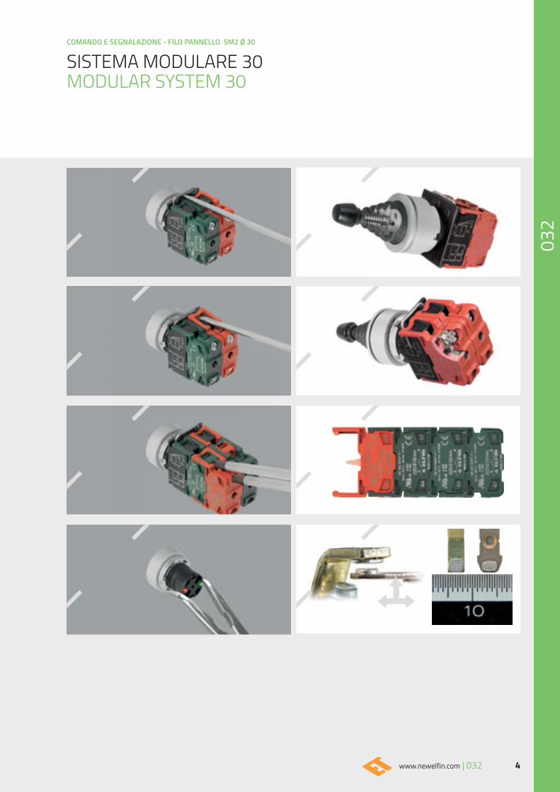
Tutti gli operatori possono essere fissati con ghiere metalliche.L'accoppiamento plastica / metallo garantisce serraggi sicuri e permanenti. L'ancoraggio tra operatori ed elementi di contatto o elementi portalampada, è costruito con un profondo incasso poi trattenuto con una molla in acciaio inox.La struttura degli elementi di contatto è realizzata con estrema robustezza e flessibilità. La componibilità del sistema permette di comporre gli elementi retro pannello in molteplici configurazioni.La dimensionatura dei blocchi e le sezioni dei sistemi di ùserraggio garantiscono notevole resistenza alle tensioni da strappo. I contatti degli operatori New Elfin sono caratterizzati dalle grandi dimensioni delle superfici di contatto e dalla particolare conformazione che garantisce performance di efficienza operativa e di durata superiori alla media. I nostri prodotti sono progettati e costruiti con tecnopolimeriHi-tech . Gli spessori applicati e l'aggiunta di materiale dirinforzo conferiscono a tutte le parti grande robustezza e resistenza.Le parti metalliche interne sono in acciaio inox o in acciaio trattato, mentre le guarnizioni in gomma resistono a tutte le condizioni climatiche.
DISPOSITIVI D'EMERGENZA
Tutti i sistemi di comando possono essere dotati di unesclusivo dispositivo di arresto d'emergenza, che difende i segnali di arresto di emergenza, mantenendoli coerentiai requisiti per i quali sono stati progettati.Il dispositivo neutralizza fattori esterni non controllabili quali forti shock, corrosioni, errori di utilizzo, inadeguata manutenzione ecc.
THE 032 SERIES
The 032 ''MODULAR SYSTEM 30" series is designed for a safe, easy, intuitive use; the solutions adopted facilitate the execution of a range of combinations guaranteeing time and resources saving. Assembly and maintenance can be performed by using standard tools and with easy access to the operators. The body in anodyzed aluminum allows a flush mountig, giving elegance and functionality to the control panel
STRUCTURE
All operators can be secured by metal locking rings . The plastic / metal combination guarantee secure and permanent tightening.The anchoring mechanism between operators and contact blocks or lampholders consists of a deep recess and a stainless steel spring holding the operator in place.The structure of the contact blocks is extremely sturdy and flexible.The modular system allows to compose the rear panel elements in multiple configurations.The block size and the sections of the tightening systems guarantee considerable tear resistance.The New Elfin operator contacts feature a large-sized contact surface and a special shape which guarantee above-average efficiency and life.Our products are designed and manufactured using Hi-tech technopolymers.The thickness applied and the addition of reinforcement material give all parts great sturdiness and resistance.The internal metallic parts are in stainless or treated steel,while the rubber gaskets are resistant to all climatic conditions.
EMERGENCY DEVICES
All command systems can be equipped with an exclusive emergency stop device, which protects the emergency stop signals, keeping them coherent to the design requirements. The device neutralizes external uncontrollable factors, such as strong shocks, corrosion, incorrect use, unsuitable maintenance, etc.
SISTEMA MODULARE 30MODULAR SYSTEM 30
4www.newelfin.com | 032
COMANDO E SEGNALAZIONE - FILO PANNELLO SM2 Ø 30
SISTEMA MODULARE 30MODULAR SYSTEM 30
COMANDO E SEGNALAZIONE - FILO PANNELLO SM2 Ø 30
5 032 | www.newelfin.com
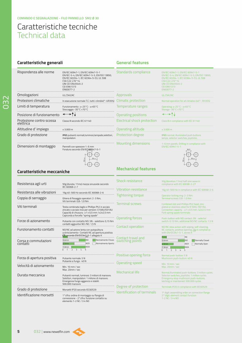
Standards compliance EN/IEC 60947-1, EN/IEC 60947-5-1 EN/IEC-5-4, EN/IEC 60947-5-5, EN/ISO 13850, EN/IEC 60204-1, IEC 60364-5-53, UL 508 CSA C22-2 N°14 UNI CEI EN45545-2 CEI EN61373 EN60077-2
Approvals UL,CSA,EAC
Climatic protection Normal operation for all climates (40°- RH35%)
Temperature ranges Operating: ≥-25°C÷ ≤+65°C Storage -35°C +70°C
Operating positions
Electrical shock protection Class II in compliance with IEC 61140
Operating altitude ≤ 3.000 m
Protection degree IP65 normal, illuminated push buttons lamps, selector switches, joysticks .
Mounting dimensions 1÷6 mm panels. Drilling in compliance with EN/IEC 60947-5-1
Mechanical features
Shock resistance 50g (duration:11ms) half sine wave in compliance with IEC 60068-2-27
Vibration resistance 16g 40÷500 Hz in compliance with IEC 60068-2-6
Tightening torque Operator locking ring: 2÷3 Nm. Terminal screws: 0.8÷1.0 Nm
Terminal screws Combined slot and Phillips Ph2 head, zinc plated or stainless steel for E10AU /E01AU. Connection capacity : ≥1 x 0.5 mm /≤2x2.5 mm Fork spring spade terminals
Operating forces Push-button with NO contact: 5N - selector switch: 0.15 Nm, additional NO/NC contacts: 1.5 N
Contact operation NO/NC slow action with wiping, self-cleaning. NC contacts, positive opening in compliance with EN/EIC947-5-1, annex K Contact travel and switching points
Positive opening force Normal push-button: 5 N Mushroom push-button: 40 N
Operating speed Min. 10 mm / sec Max. 20mm / sec
Mechanical life Normal,illuminated push-buttons: 3 million cycles. Selector switches, joysticks: 1 million cycles. Emergency stop mushroom push-buttons, latching or maintained: 500.000 cycles
Degree of protection Terminals IP20 in compliance with IEC60529
Identification of terminals 1st digit: assembling order on connection flange 2nd digit: element contact function 1-2 NC / 3-4 NO
1mm NCNO Normally Closed
Normally OpenNCRNOA
1 2 3 4 50
3.6mm
2.5mm1.9mm
Rispondenza alle norme EN/IEC 60947-1, EN/IEC 60947-5-1 EN/IEC-5-4, EN/IEC 60947-5-5, EN/ISO 13850, EN/IEC 60204-1, IEC 60364-5-53, UL 508 CSA C22-2 N°14 UNI CEI EN45545-2 CEI EN61373 EN60077-2
Omologazioni UL,CSA,EAC
Protezioni climatiche In esecuzione normale T.C. tutti i climi(40°-UR35%)
Limiti di temperatura Funzionamento : ≥-25°C÷ ≤+65°C Stoccaggio -35°C +70°C
Posizione di funzionamento
Protezione contro scossa Classe II secondo IEC 61140elettricaAltitudine d’ impiego ≤ 3.000 m
Grado di protezione IP65 pulsanti normali,luminosi,lampade,selettori, manipolatori.
Dimensioni di montaggio Pannelli con spessore 1÷6 mm Foratura secondo EN/IEC 60947-5-1
Caratteristiche meccaniche
Resistenza agli urti 50g (durata: 11ms) mezza sinusoide secondo IEC 60068-2-7
Resistenza alle vibrazioni 16g 40÷500 Hz secondo IEC 60068-2-6
Coppia di serraggio Ghiera di fissaggio operatori: 2÷3 Nm, Viti terminali: 0,8÷1,0 Nm
Viti terminali Testa combinata taglio e Phillips Ph2 in acciaio zincato o acciaio inox per versioni E10AU/E01AU Capacità di chiusura : ≥1 x 0,5 mm /≤2x2,5 mm Capicorda a forcella ''spring spade'' Forze di azionamento Pulsante con contatto NO: 5N - selettore: 0,15 Nm contatti aggiuntivi NO /NC: 1,5 N
Funzionamento contatti NO/NC ad azione lenta con autopulitura a strisciamento- Contatti NC ad apertura positiva secondo EN/EIC947-5-1 allegato K Corsa e commutazionicontatti
Forza di apertura positiva Pulsante normale: 5 N Pulsante a fungo: 40 N
Velocità di azionamento Min. 10 mm / sec Max. 20mm / sec Durata meccanica Pulsanti normali, luminosi: 3 milioni di manovre. Selettori, manipolatori: 1 milione di manovre. Emergenza fungo aggancio e stabili: 500.000 manovre
Grado di protezione Morsetti IP20 secondo IEC60529
Identificazione morsetti 1°cifra: ordine di montaggio su flangia di connessione - 2°cifra: funzione contatto su elemento 1-2 NC / 3 4 NO
1mm NCNO Normalmente Chiuso
Normalmente ApertoNCRNOA
1 2 3 4 50
3,6mm2,5mm1,9mm
Caratteristiche generali General features
Caratteristiche tecniche Technical data
6www.newelfin.com | 032
COMANDO E SEGNALAZIONE - FILO PANNELLO SM2 Ø 30
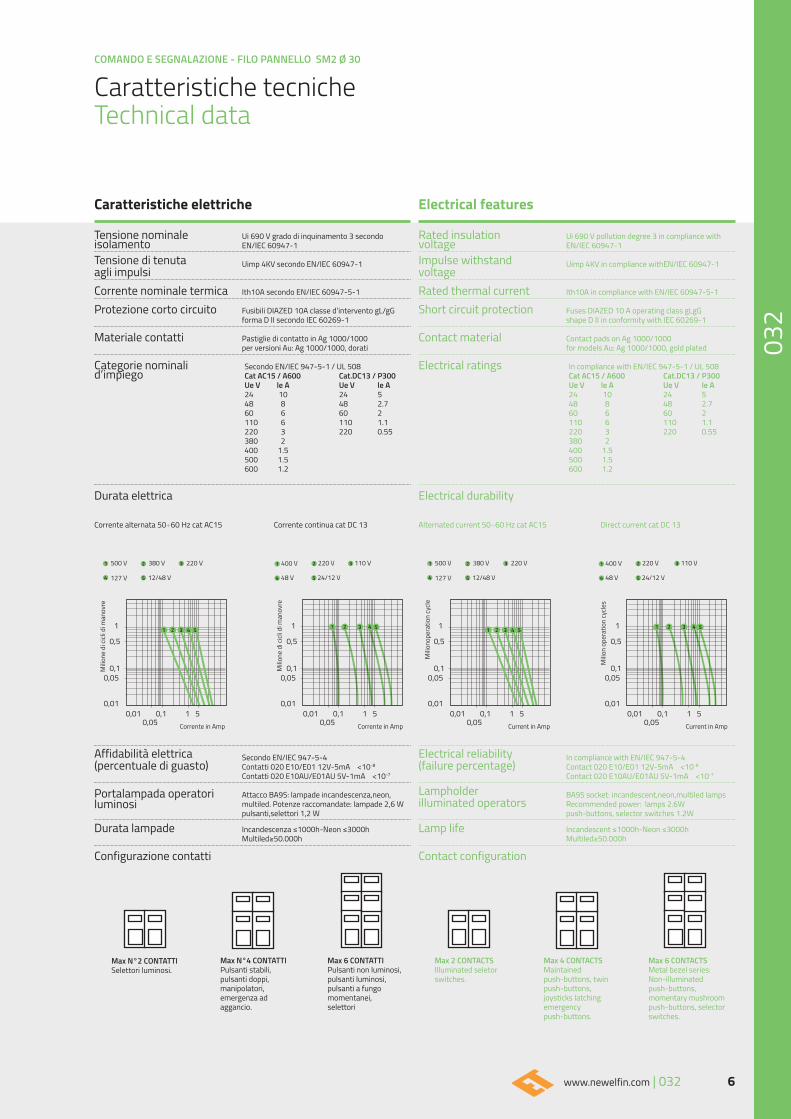
Rated insulation Ui 690 V pollution degree 3 in compliance withvoltage EN/IEC 60947-1
Impulse withstand Uimp 4KV in compliance withEN/IEC 60947-1voltageRated thermal current Ith10A in compliance with EN/IEC 60947-5-1
Short circuit protection Fuses DIAZED 10 A operating class gLgG shape D II in conformity with IEC 60269-1
Contact material Contact pads on Ag 1000/1000 for models Au: Ag 1000/1000, gold plated
Electrical ratings In compliance with EN/IEC 947-5-1 / UL 508 Cat AC15 / A600 Cat.DC13 / P300 Ue V le A Ue V le A 24 10 24 5 48 8 48 2.7 60 6 60 2 110 6 110 1.1 220 3 220 0.55 380 2 400 1.5 500 1.5 600 1.2
Electrical durability
Alternated current 50÷60 Hz cat AC15 Direct current cat DC 13
Electrical reliability In compliance with EN/IEC 947-5-4(failure percentage) Contact 020 E10/E01 12V-5mA <10-8
Contact 020 E10AU/E01AU 5V-1mA <10-7
Lampholder BA9S socket: incandescent,neon,multiled lampsilluminated operators Recommended power: lamps 2.6W push-buttons, selector switches 1.2W
Lamp life Incandescent ≤1000h-Neon ≤3000h Multiled≥50.000h
Contact configuration
Tensione nominale Ui 690 V grado di inquinamento 3 secondoisolamento EN/IEC 60947-1
Tensione di tenuta Uimp 4KV secondo EN/IEC 60947-1agli impulsiCorrente nominale termica Ith10A secondo EN/IEC 60947-5-1
Protezione corto circuito Fusibili DIAZED 10A classe d’intervento gL/gG forma D II secondo IEC 60269-1
Materiale contatti Pastiglie di contatto in Ag 1000/1000 per versioni Au: Ag 1000/1000, dorati
Categorie nominali Secondo EN/IEC 947-5-1 / UL 508d’impiego Cat AC15 / A600 Cat.DC13 / P300 Ue V le A Ue V le A 24 10 24 5 48 8 48 2.7 60 6 60 2 110 6 110 1.1 220 3 220 0.55 380 2 400 1.5 500 1.5 600 1.2
Durata elettrica
Corrente alternata 50÷60 Hz cat AC15 Corrente continua cat DC 13
Affidabilità elettrica Secondo EN/IEC 947-5-4(percentuale di guasto) Contatti 020 E10/E01 12V-5mA <10-8
Contatti 020 E10AU/E01AU 5V-1mA <10-7
Portalampada operatori Attacco BA9S: lampade incandescenza,neon, luminosi multiled. Potenze raccomandate: lampade 2,6 W pulsanti,selettori 1,2 W
Durata lampade Incandescenza ≤1000h-Neon ≤3000h Multiled≥50.000h
Configurazione contatti
Caratteristiche elettriche Electrical features
Caratteristiche tecniche Technical data
1 1
0,5 0,5
0,1 0,10,05 0,05
0,010,01 0,01
0,05 0,050,1 0,11 15 5
0,01
Milio
ne d
i cicl
i di m
anov
re
Milio
ne d
i cicl
i di m
anov
re
Corrente in Amp
500 V 400 V380 V 220 V220 V 110 V
127 V 48 V12/48 V 24/12 V
1 1
0,5 0,5
0,1 0,10,05 0,05
0,010,01 0,01
0,05 0,050,1 0,11 15 5
0,01
Milio
nope
ratio
n cy
cle
Milio
n op
erat
ion
cycle
s
Current in Amp
500 V 400 V380 V 220 V220 V 110 V
127 V 48 V12/48 V 24/12 V
Corrente in Amp Current in Amp
Max N°4 CONTATTIPulsanti stabili,pulsanti doppi, manipolatori,emergenza ad aggancio.
Max 4 CONTACTSMaintained push-buttons, twin push-buttons, joysticks latching emergency push-buttons.
Max 6 CONTATTI Pulsanti non luminosi,pulsanti luminosi, pulsanti a fungomomentanei, selettori
Max 6 CONTACTSMetal bezel series:Non-illuminated push-buttons, momentary mushroom push-buttons, selector switches.
Max N°2 CONTATTISelettori luminosi.
Max 2 CONTACTSIlluminated seletor switches.
COMANDO E SEGNALAZIONE - FILO PANNELLO SM2 Ø 30
7 032 | www.newelfin.com
8www.newelfin.com | 032
COMANDO E SEGNALAZIONE - FILO PANNELLO SM2 Ø 30
COMANDO E SEGNALAZIONE - FILO PANNELLO SM2 Ø 30
9 032 | www.newelfin.com
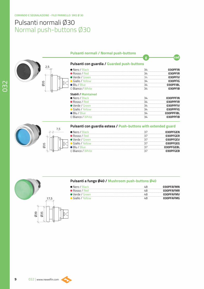
Pulsanti normali Ø30Normal push-buttons Ø30
Pulsanti con guardia / Guarded push-buttons
Nero / Black 34 030PFIN Rosso / Red 34 030PFIR Verde / Green 34 030PFIV Giallo / Yellow 34 030PFIG Blu / Blue 34 030PFIBL Bianco / White 34 030PFIB
Stabili / Maintained Nero / Black 34 030PPFIN Rosso / Red 34 030PPFIR Verde / Green 34 030PPFIV Giallo / Yellow 34 030PPFIG Blu / Blue 34 030PPFIBL Bianco / White 34 030PPFIB
Pulsanti con guardia estesa / Push-buttons with extended guard Nero / Black 37 030PFGEN Rosso / Red 37 030PFGER Verde / Green 37 030PFGEV Giallo / Yellow 37 030PFGEG Blu / Blue 37 030PFGEBL Bianco / White 37 030PFGEB
Pulsanti a fungo Ø40 / Mushroom push-buttons Ø40 Nero / Black 48 030PFAFMN Rosso / Red 48 030PFAFMR Verde / Green 48 030PFAFMV Giallo / Yellow 48 030PFAFMG
Pulsanti normali / Normal push-buttons
Ø35
2,5
Ø35
Ø39
17,5
7,5
Ø35
10www.newelfin.com | 032
COMANDO E SEGNALAZIONE - FILO PANNELLO SM2 Ø 30
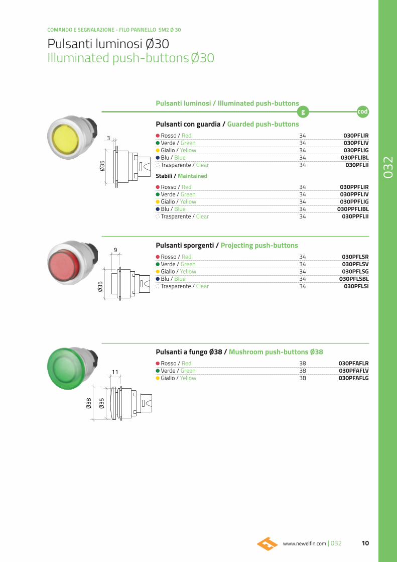
Pulsanti luminosi Ø30Illuminated push-buttons Ø30
Pulsanti con guardia / Guarded push-buttons
Rosso / Red 34 030PFLIR Verde / Green 34 030PFLIV Giallo / Yellow 34 030PFLIG Blu / Blue 34 030PFLIBL Trasparente / Clear 34 030PFLII
Stabili / Maintained
Rosso / Red 34 030PPFLIR Verde / Green 34 030PPFLIV Giallo / Yellow 34 030PPFLIG Blu / Blue 34 030PPFLIBL Trasparente / Clear 34 030PPFLII
Pulsanti sporgenti / Projecting push-buttons
Rosso / Red 34 030PFLSR Verde / Green 34 030PFLSV Giallo / Yellow 34 030PFLSG Blu / Blue 34 030PFLSBL Trasparente / Clear 34 030PFLSI
Pulsanti a fungo Ø38 / Mushroom push-buttons Ø38 Rosso / Red 38 030PFAFLR Verde / Green 38 030PFAFLV Giallo / Yellow 38 030PFAFLG
Pulsanti luminosi / Illuminated push-buttons
3
Ø35
Ø35
9
Ø38
Ø35
11
COMANDO E SEGNALAZIONE - FILO PANNELLO SM2 Ø 30
11 032 | www.newelfin.com
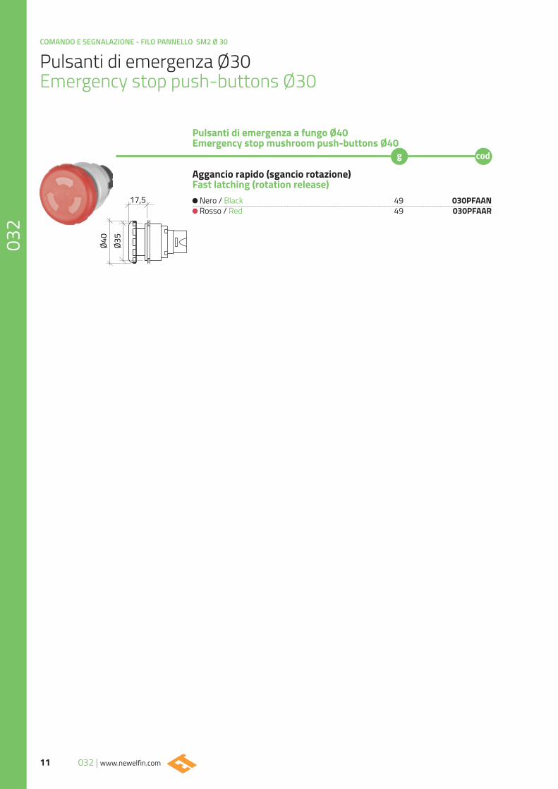
Pulsanti di emergenza Ø30Emergency stop push-buttons Ø30
Aggancio rapido (sgancio rotazione)Fast latching (rotation release)
Nero / Black 49 030PFAAN Rosso / Red 49 030PFAAR
Pulsanti di emergenza a fungo Ø40Emergency stop mushroom push-buttons Ø40
Ø35
17,5
Ø40
12www.newelfin.com | 032
COMANDO E SEGNALAZIONE - FILO PANNELLO SM2 Ø 30
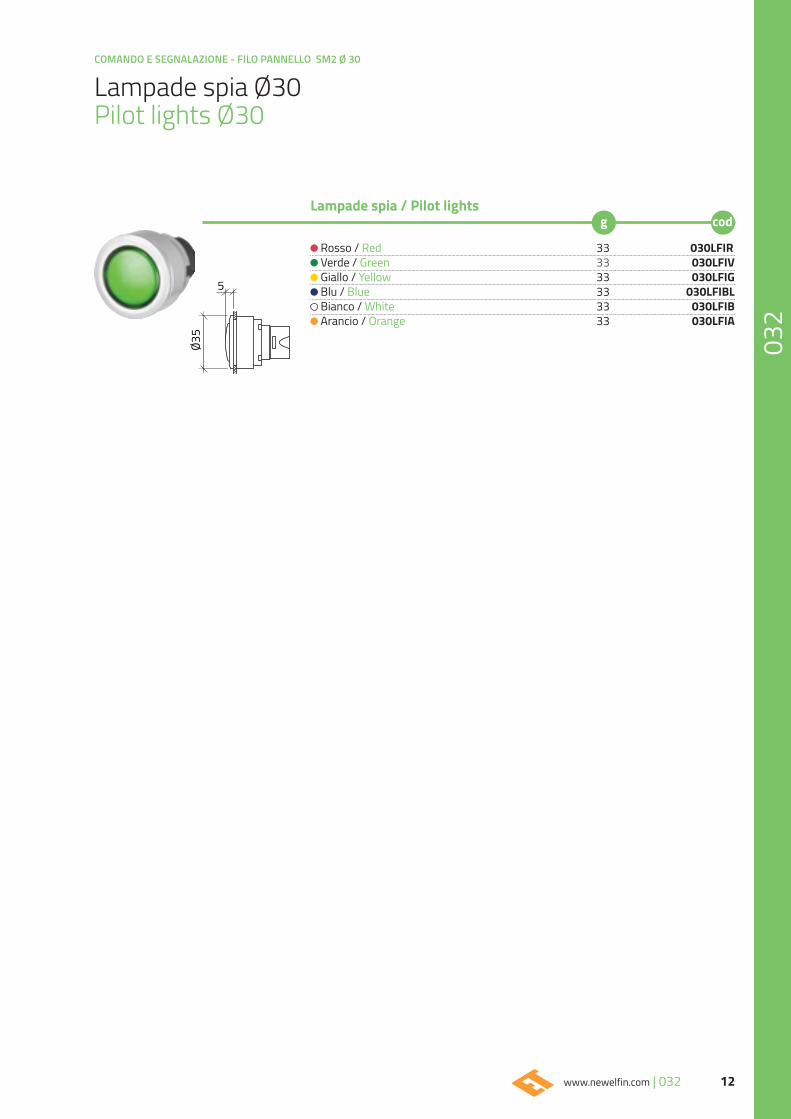
Lampade spia Ø30Pilot lights Ø30
Rosso / Red 33 030LFIR Verde / Green 33 030LFIV Giallo / Yellow 33 030LFIG Blu / Blue 33 030LFIBL Bianco / White 33 030LFIB Arancio / Orange 33 030LFIA
Lampade spia / Pilot lights
5
Ø35
COMANDO E SEGNALAZIONE - FILO PANNELLO SM2 Ø 30
13 032 | www.newelfin.com
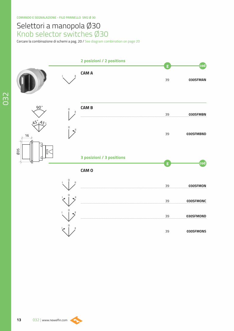
Selettori a manopola Ø30Knob selector switches Ø30Cercare la combinazione di schemi a pag. 20 / See diagram combination on page 20
CAM A 39 030SFMAN
CAM B 39 030SFMBN
39 030SFMBND
3 posizioni / 3 positions
CAM O
39 030SFMON
39 030SFMONC
39 030SFMOND
39 030SFMONS
2 posizioni / 2 positions
I II
II0
II0
I
0III
0
0
II
II
I
I
0II
90˚
45˚45˚
Ø35
16
14www.newelfin.com | 032
COMANDO E SEGNALAZIONE - FILO PANNELLO SM2 Ø 30
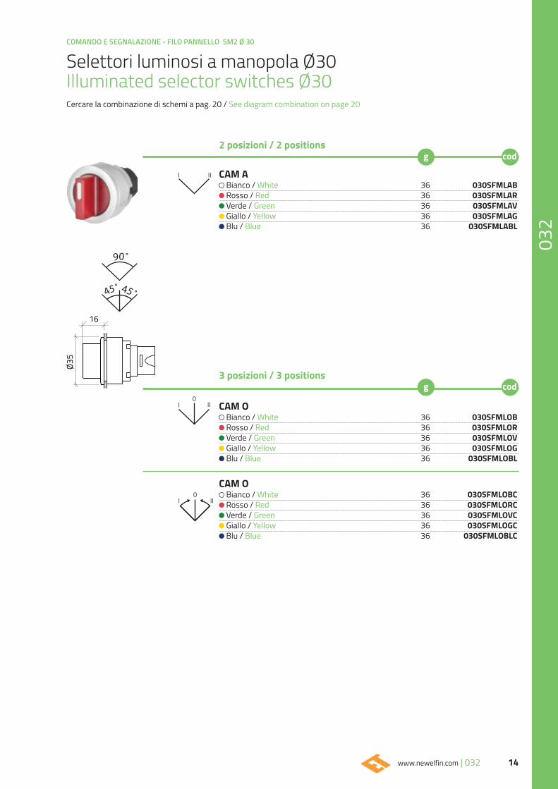
Selettori luminosi a manopola Ø30Illuminated selector switches Ø30Cercare la combinazione di schemi a pag. 20 / See diagram combination on page 20
CAM A Bianco / White 36 030SFMLAB Rosso / Red 36 030SFMLAR Verde / Green 36 030SFMLAV Giallo / Yellow 36 030SFMLAG Blu / Blue 36 030SFMLABL
3 posizioni / 3 positions
CAM O Bianco / White 36 030SFMLOB Rosso / Red 36 030SFMLOR Verde / Green 36 030SFMLOV Giallo / Yellow 36 030SFMLOG Blu / Blue 36 030SFMLOBL
CAM O Bianco / White 36 030SFMLOBC Rosso / Red 36 030SFMLORC Verde / Green 36 030SFMLOVC Giallo / Yellow 36 030SFMLOGC Blu / Blue 36 030SFMLOBLC
2 posizioni / 2 positions
I II
I0
II
I0
II
90˚
Ø35
16
45˚45˚
COMANDO E SEGNALAZIONE - FILO PANNELLO SM2 Ø 30
15 032 | www.newelfin.com
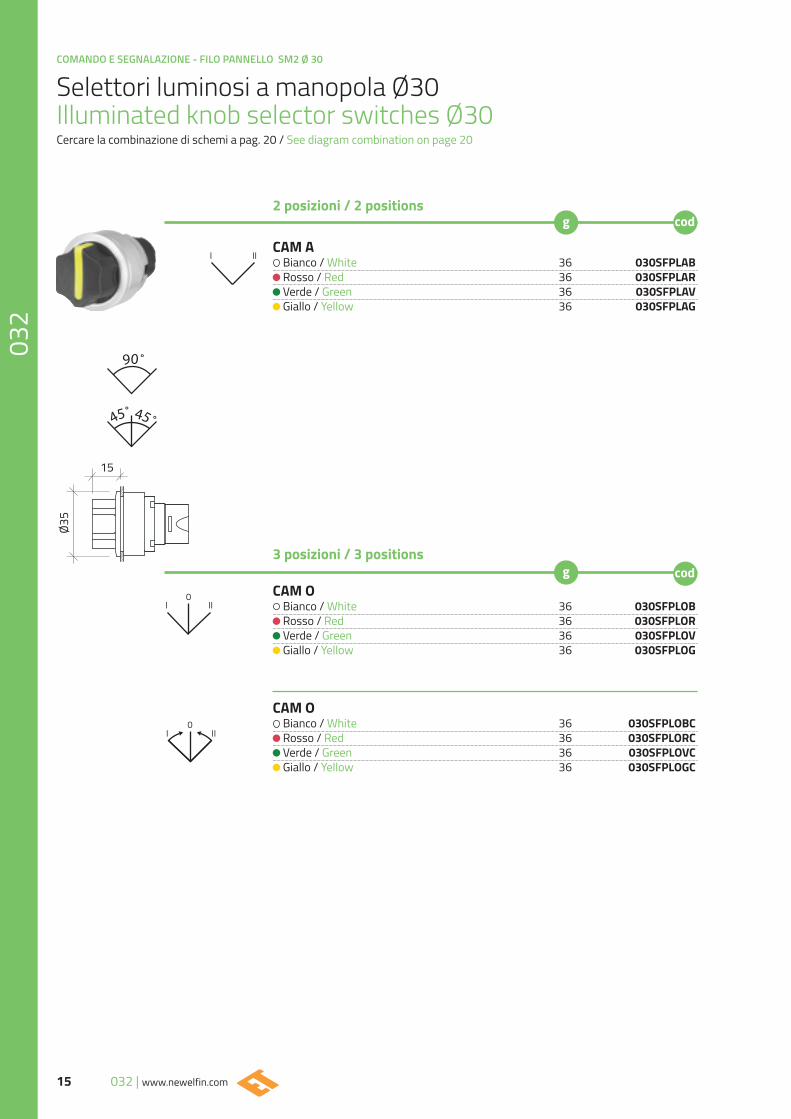
Selettori luminosi a manopola Ø30Illuminated knob selector switches Ø30Cercare la combinazione di schemi a pag. 20 / See diagram combination on page 20
CAM A Bianco / White 36 030SFPLAB Rosso / Red 36 030SFPLAR Verde / Green 36 030SFPLAV Giallo / Yellow 36 030SFPLAG
3 posizioni / 3 positions
CAM O Bianco / White 36 030SFPLOB Rosso / Red 36 030SFPLOR Verde / Green 36 030SFPLOV Giallo / Yellow 36 030SFPLOG
CAM O Bianco / White 36 030SFPLOBC Rosso / Red 36 030SFPLORC Verde / Green 36 030SFPLOVC Giallo / Yellow 36 030SFPLOGC
2 posizioni / 2 positions
I II
II0
I
I0
II
90˚
45˚45˚
Ø35
15
16www.newelfin.com | 032
COMANDO E SEGNALAZIONE - FILO PANNELLO SM2 Ø 30
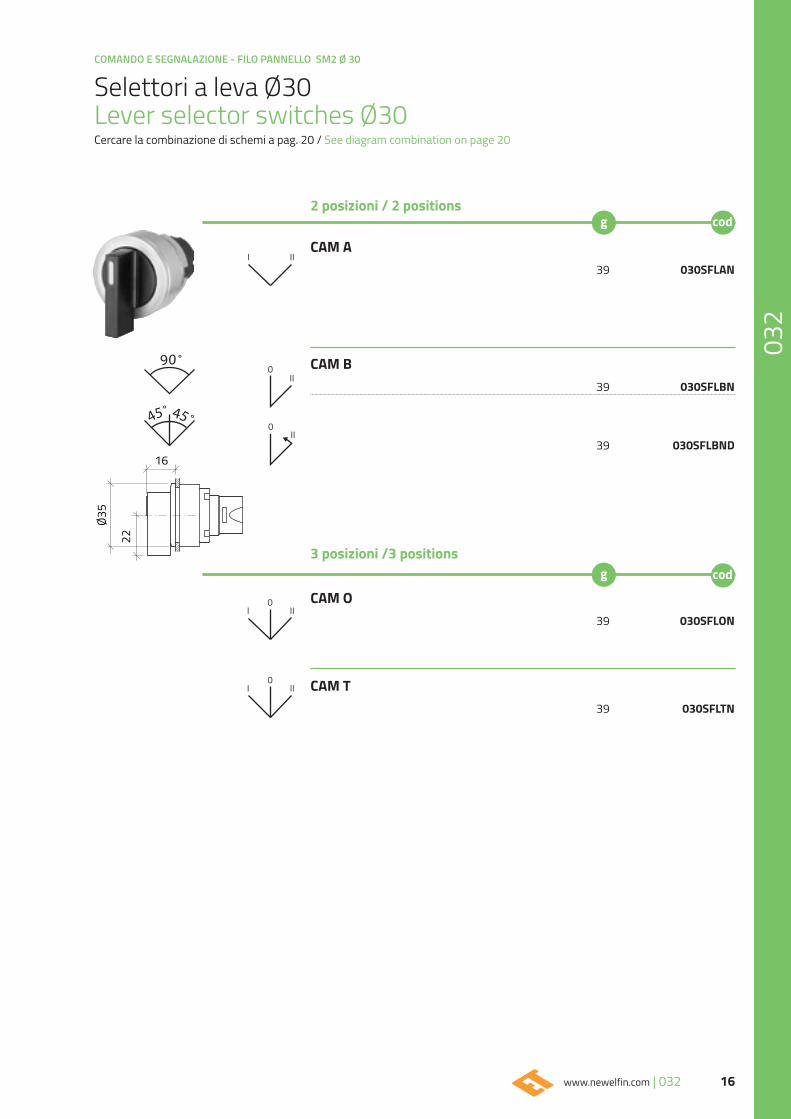
Selettori a leva Ø30Lever selector switches Ø30Cercare la combinazione di schemi a pag. 20 / See diagram combination on page 20
CAM A 39 030SFLAN
CAM B 39 030SFLBN
39 030SFLBND
3 posizioni /3 positions
CAM O 39 030SFLON
CAM T 39 030SFLTN
2 posizioni / 2 positions
I II
II0
II
II
0
0
I
I
0II
90˚
45˚45˚
Ø35
22
16
COMANDO E SEGNALAZIONE - FILO PANNELLO SM2 Ø 30
17 032 | www.newelfin.com
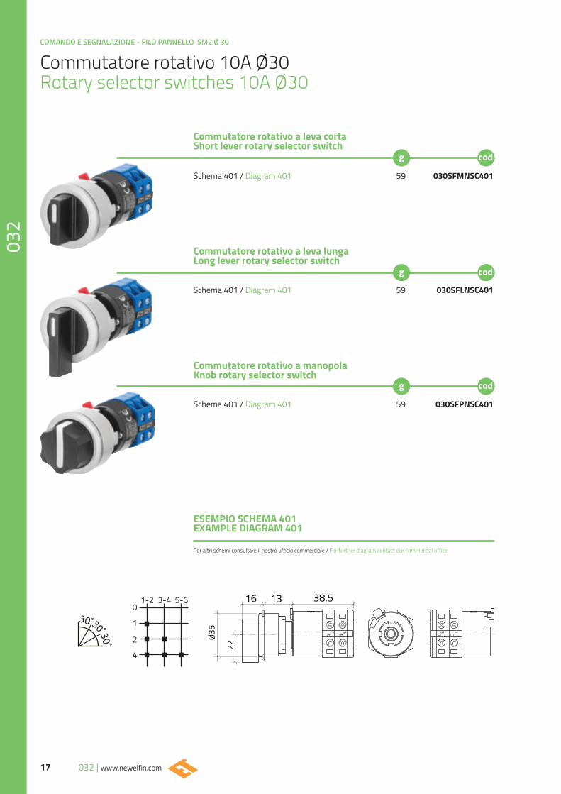
Commutatore rotativo 10A Ø30Rotary selector switches 10A Ø30
Schema 401 / Diagram 401 59 030SFMNSC401
Schema 401 / Diagram 401 59 030SFLNSC401
Schema 401 / Diagram 401 59 030SFPNSC401
Commutatore rotativo a leva cortaShort lever rotary selector switch
Commutatore rotativo a leva lungaLong lever rotary selector switch
Commutatore rotativo a manopola Knob rotary selector switch
ESEMPIO SCHEMA 401EXAMPLE DIAGRAM 401
1-20
1
2
4
3-4 5-6
Ø35
22
16 13 38,5
Per altri schemi consultare il nostro ufficio commerciale / For further diagram contact our commercial office
18www.newelfin.com | 032
COMANDO E SEGNALAZIONE - FILO PANNELLO SM2 Ø 30
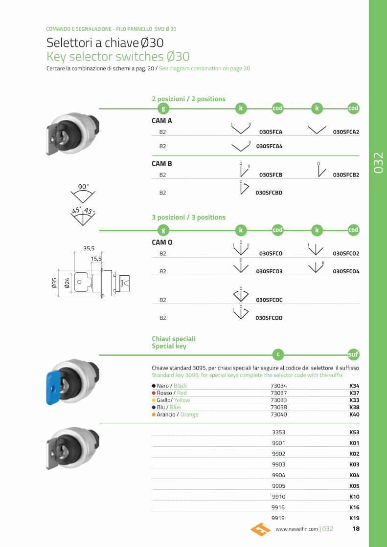
Selettori a chiave Ø30Key selector switches Ø30Cercare la combinazione di schemi a pag. 20 / See diagram combination on page 20
2 posizioni / 2 positions
CAM O 82 030SFCO 030SFCO2 82 030SFCO3 030SFCO4
82 030SFCOC
82 030SFCOD
3 posizioni / 3 positions
90˚
45˚45˚
I 0 II
0 II
I
0
I0
I II I
II
00 II
CAM A 82 030SFCA 030SFCA2 82 030SFCA4
CAM B 82 030SFCB 030SFCB2
82 030SFCBD
0
Ø35
35,5
15,5
Ø24
Chiavi specialiSpecial key
Chiave standard 3095, per chiavi speciali far seguire al codice del selettore il suffissoStandard key 3095, for special keys complete the selector code with the suffix
Nero / Black 73034 K34 Rosso / Red 73037 K37 Giallo/ Yellow 73033 K33 Blu / Blue 73038 K38 Arancio / Orange 73040 K40
3353 K53 9901 K01 9902 K02 9903 K03 9904 K04 9905 K05 9910 K10 9916 K16 9919 K19
COMANDO E SEGNALAZIONE - FILO PANNELLO SM2 Ø 30
19 032 | www.newelfin.com
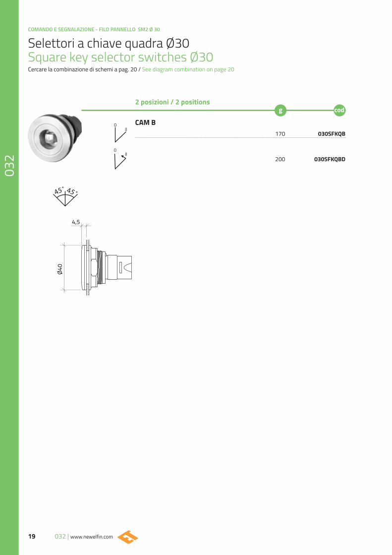
Selettori a chiave quadra Ø30Square key selector switches Ø30Cercare la combinazione di schemi a pag. 20 / See diagram combination on page 20
CAM B 170 030SFKQB
200 030SFKQBD
2 posizioni / 2 positions
II0
0II
45˚45˚
Ø40
4,5
20www.newelfin.com | 032
COMANDO E SEGNALAZIONE - FILO PANNELLO SM2 Ø 30
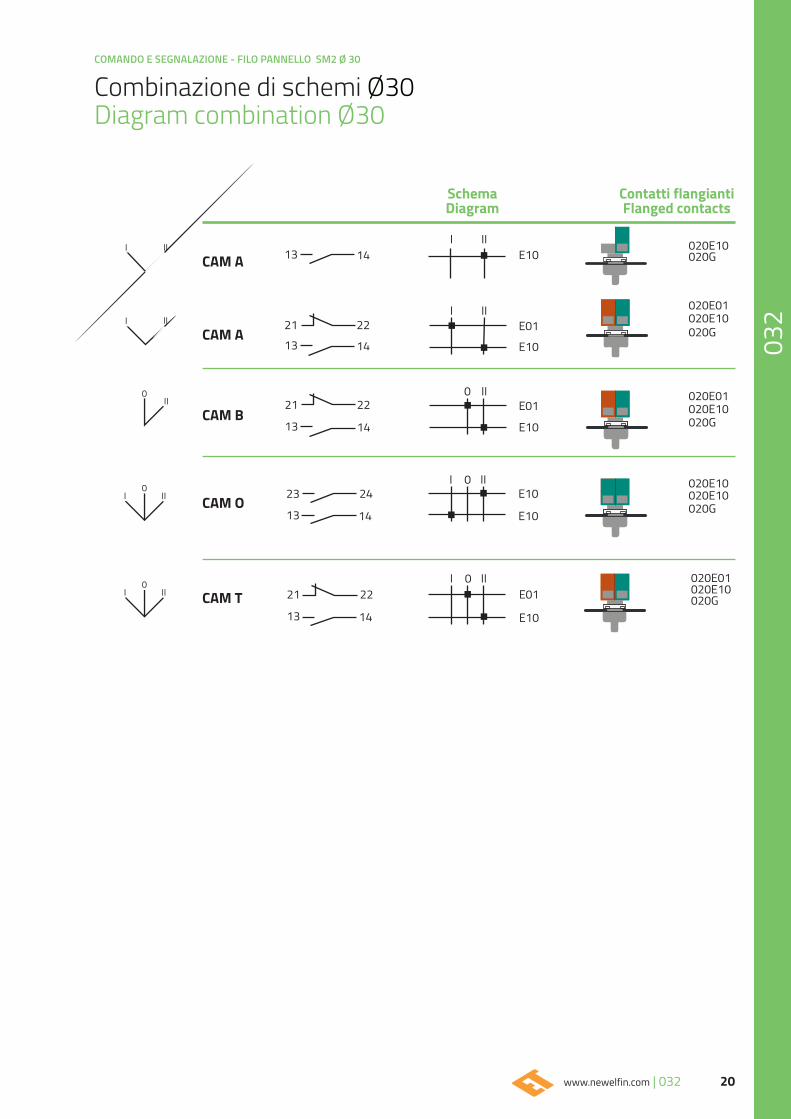
Combinazione di schemi Ø30Diagram combination Ø30
SchemaDiagram
Contatti flangiantiFlanged contacts
CAM A
CAM A
CAM B
CAM O
CAM T
13
1321
14
14
22
I
I
0
I
II
II
II
0 II
E10
E10
E10
E10
E10
E01
E01
020G
020G
020G
020G
020E10
020E10
020E10
020E10
020E01
020E01
020E10
I II
I II
0II
0
0
II
II
I
I
13
21
14
22
13
23
14
24
13
21
14
22I 0 II
E10
E01 020G020E10020E01
COMANDO E SEGNALAZIONE - FILO PANNELLO SM2 Ø 30
21 032 | www.newelfin.com
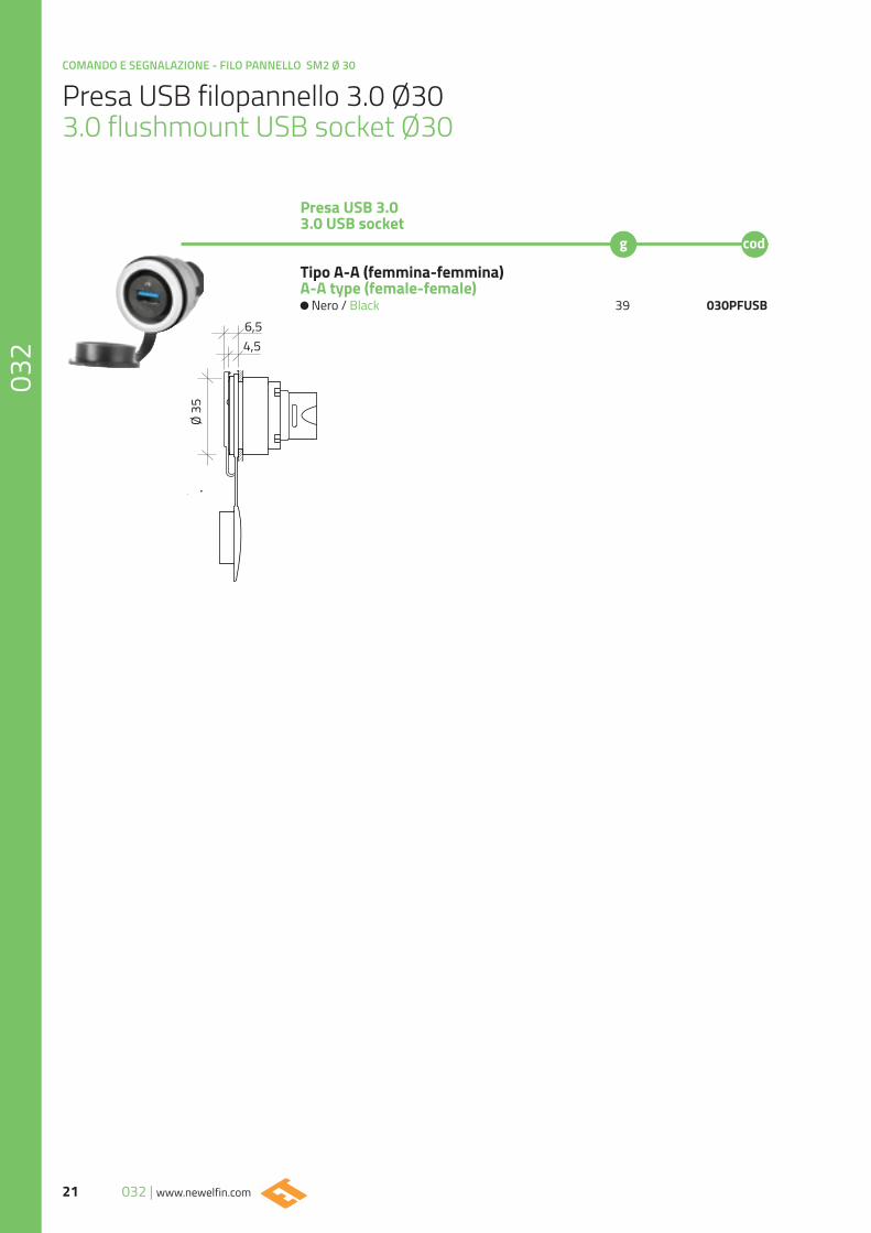
Presa USB filopannello 3.0 Ø303.0 flushmount USB socket Ø30
Presa USB 3.03.0 USB socket
Tipo A-A (femmina-femmina)A-A type (female-female)
Nero / Black 39 030PFUSB
Ø 35
4,56,5
22www.newelfin.com | 032
COMANDO E SEGNALAZIONE - FILO PANNELLO SM2 Ø 30
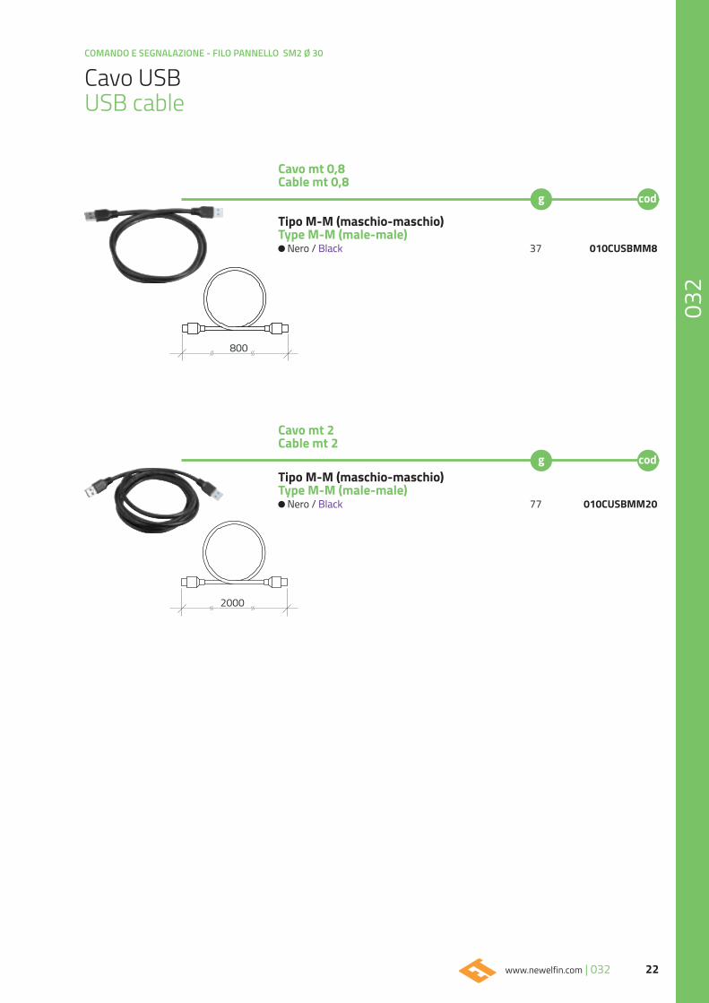
Cavo mt 0,8Cable mt 0,8
Cavo mt 2Cable mt 2
Cavo USB USB cable
Tipo M-M (maschio-maschio)Type M-M (male-male)
Nero / Black 37 010CUSBMM8
Tipo M-M (maschio-maschio)Type M-M (male-male)
Nero / Black 77 010CUSBMM20
2000
800
COMANDO E SEGNALAZIONE - FILO PANNELLO SM2 Ø 30
23 032 | www.newelfin.com
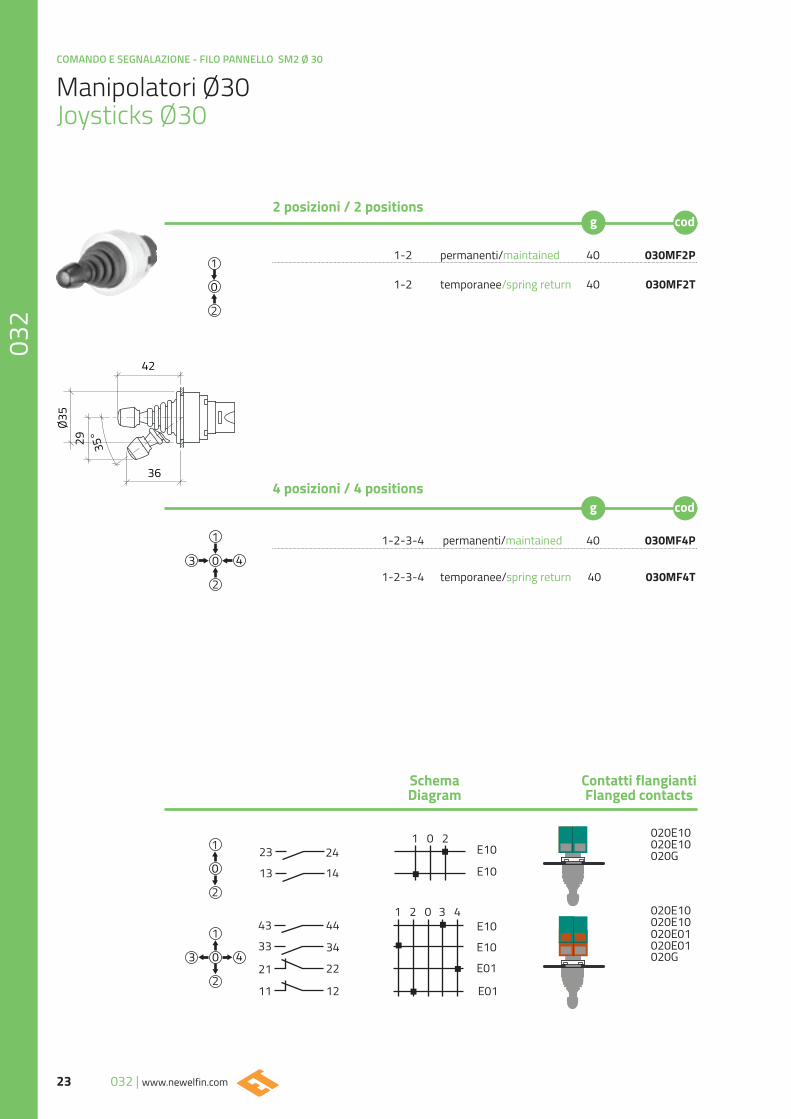
1-2 permanenti/maintained 40 030MF2P
1-2 temporanee/spring return 40 030MF2T
1-2-3-4 permanenti/maintained 40 030MF4P
1-2-3-4 temporanee/spring return 40 030MF4T
Manipolatori Ø30Joysticks Ø30
2 posizioni / 2 positions
4 posizioni / 4 positions
SchemaDiagram
Contatti flangiantiFlanged contacts
13
23
11 12
22
34
44
21
33
43
14
1 0 224
1 2 0 3 4
E10
E10
E10
E10
E01
E01
020G
020G
020E10
020E01
020E10
020E10
020E01
020E10
42
36
Ø35
29 35°
24www.newelfin.com | 032
COMANDO E SEGNALAZIONE - FILO PANNELLO SM2 Ø 30
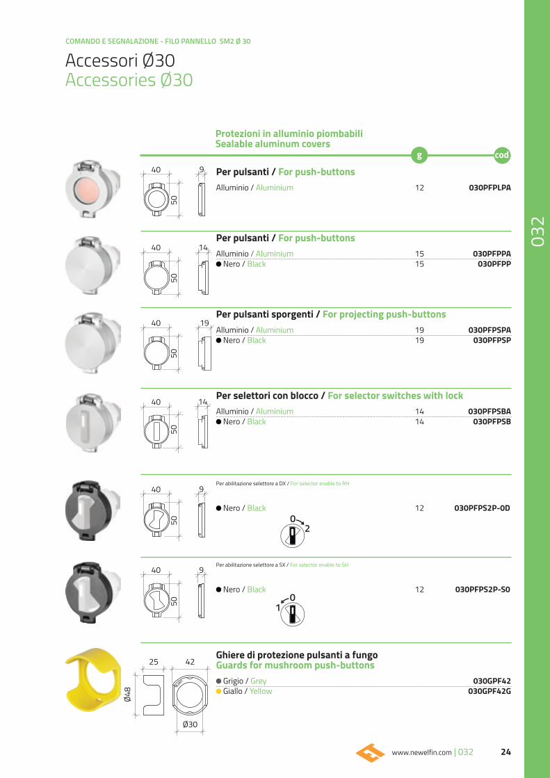
Accessori Ø30Accessories Ø30
Per pulsanti / For push-buttons
Alluminio / Aluminium 12 030PFPLPA
Per pulsanti / For push-buttons
Alluminio / Aluminium 15 030PFPPA Nero / Black 15 030PFPP
Per pulsanti sporgenti / For projecting push-buttons Alluminio / Aluminium 19 030PFPSPA
Nero / Black 19 030PFPSP
Per selettori con blocco / For selector switches with lock Alluminio / Aluminium 14 030PFPSBA
Nero / Black 14 030PFPSB
Per abilitazione selettore a DX / For selector enable to RH
Nero / Black 12 030PFPS2P-0D
Per abilitazione selettore a SX / For selector enable to SH
Nero / Black 12 030PFPS2P-S0
Ghiere di protezione pulsanti a fungoGuards for mushroom push-buttons
Grigio / Grey 030GPF42 Giallo / Yellow 030GPF42G
02
01
Protezioni in alluminio piombabili Sealable aluminum covers
25 42
Ø48
Ø30
5050
940
40
5050
5050
19
14
14
9
9
40
40
40
40
COMANDO E SEGNALAZIONE - FILO PANNELLO SM2 Ø 30
25 032 | www.newelfin.com
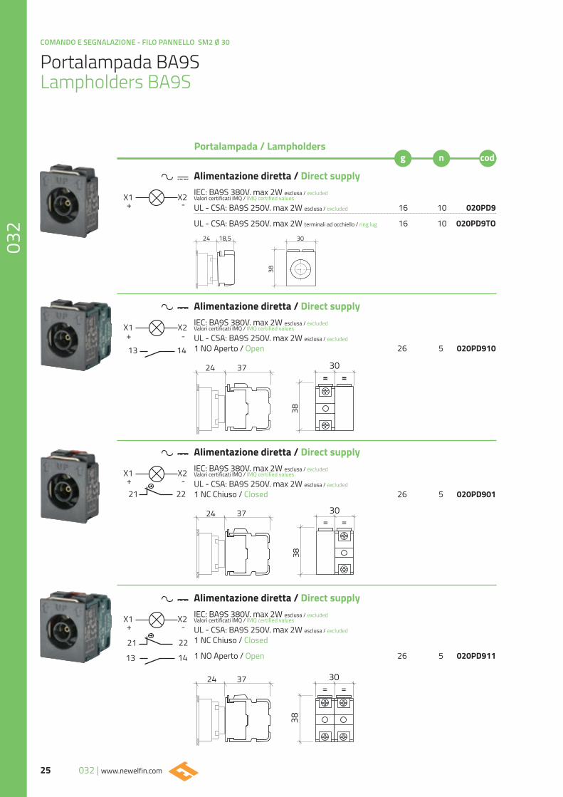
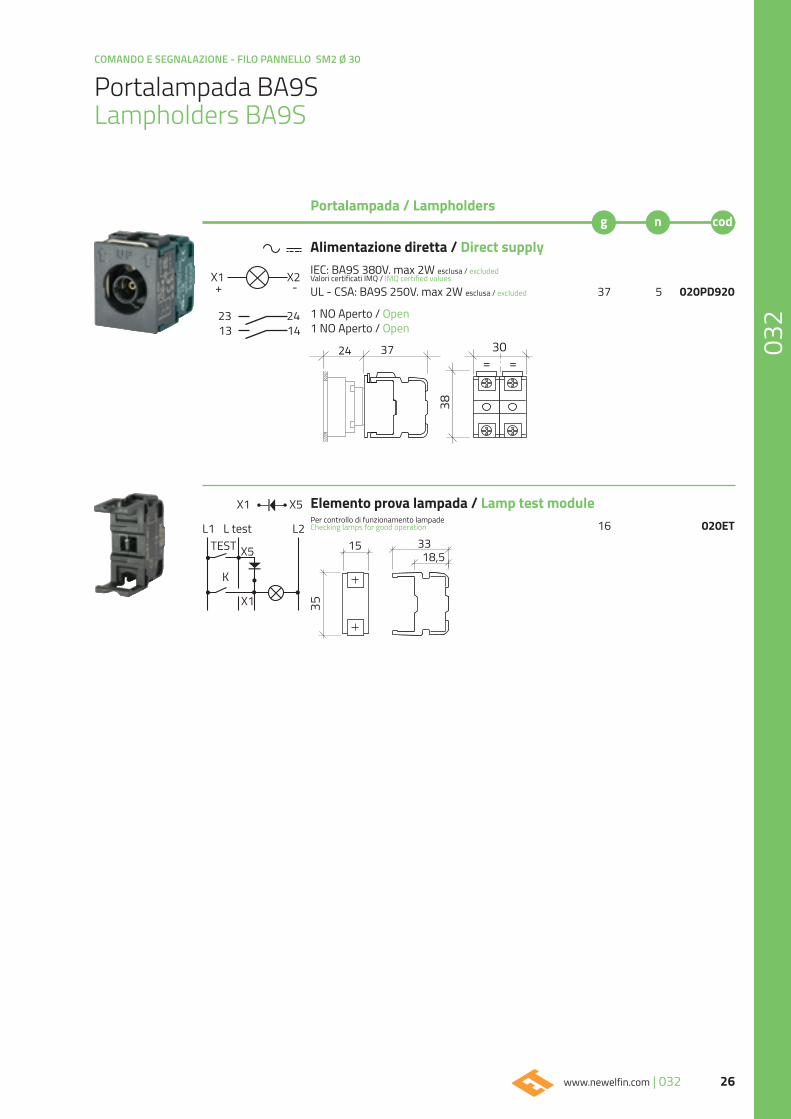
Portalampada BA9S Lampholders BA9S
Alimentazione diretta / Direct supplyIEC: BA9S 380V. max 2W esclusa / excludedValori certificati IMQ / IMQ certified values
UL - CSA: BA9S 250V. max 2W esclusa / excluded 16 10 020PD9
UL - CSA: BA9S 250V. max 2W terminali ad occhiello / ring lug 16 10 020PD9TO
Alimentazione diretta / Direct supplyIEC: BA9S 380V. max 2W esclusa / excludedValori certificati IMQ / IMQ certified values
UL - CSA: BA9S 250V. max 2W esclusa / excluded 1 NO Aperto / Open 26 5 020PD910
Alimentazione diretta / Direct supplyIEC: BA9S 380V. max 2W esclusa / excludedValori certificati IMQ / IMQ certified values
UL - CSA: BA9S 250V. max 2W esclusa / excluded 1 NC Chiuso / Closed 26 5 020PD901
Alimentazione diretta / Direct supplyIEC: BA9S 380V. max 2W esclusa / excludedValori certificati IMQ / IMQ certified values
UL - CSA: BA9S 250V. max 2W esclusa / excluded 1 NC Chiuso / Closed
1 NO Aperto / Open 26 5 020PD911
Portalampada / Lampholders
13
13
14
14
21 22
21 22
X1
X1
X1
X1
+
+
+
+
X2
X2
X2
X2
-
-
-
-
18,524 30
38
38
3724 30= == =
3724
38
30= =
38
30= =
3724
26www.newelfin.com | 032
COMANDO E SEGNALAZIONE - FILO PANNELLO SM2 Ø 30
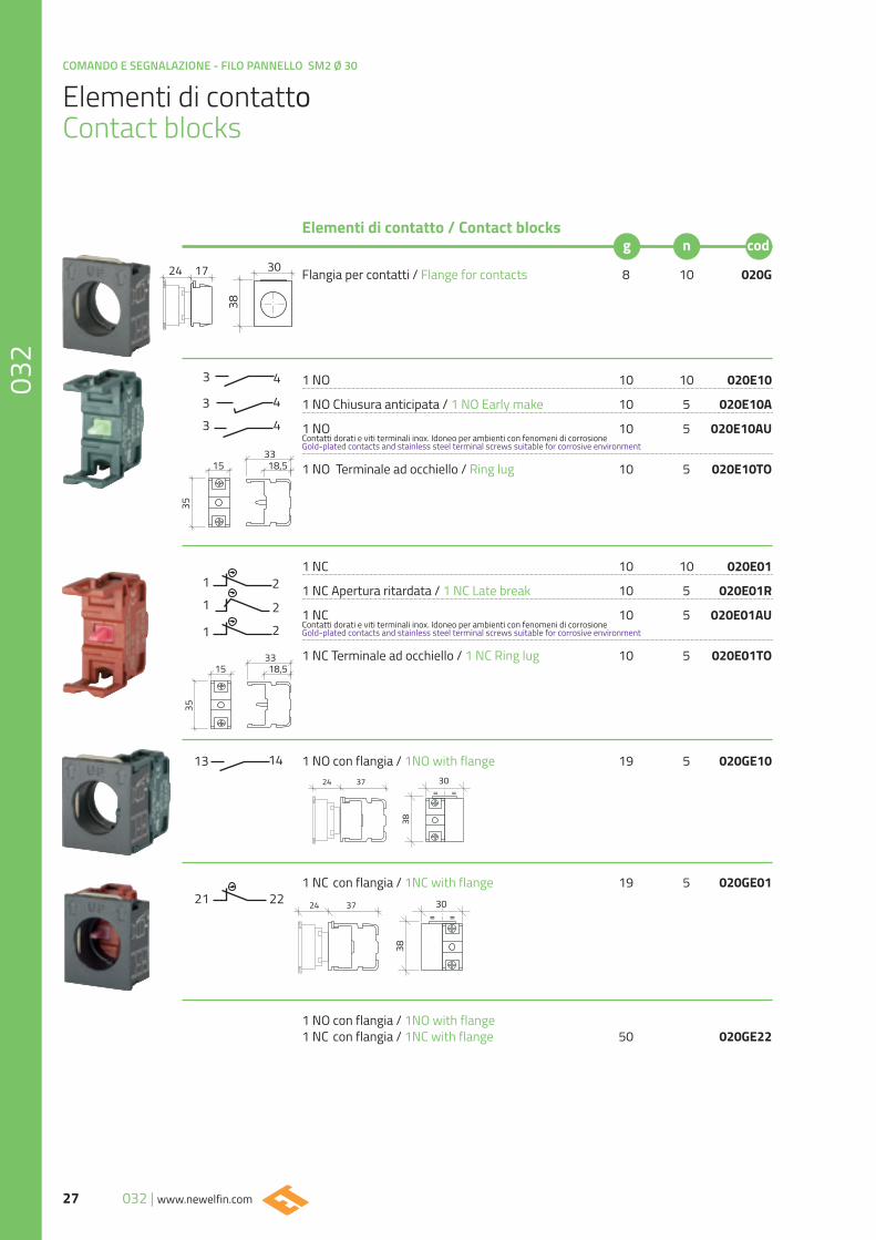
Portalampada BA9S Lampholders BA9S
Elemento prova lampada / Lamp test modulePer controllo di funzionamento lampadeChecking lamps for good operation 16 020ET
Portalampada / Lampholders
X1
L1 L test L2
X1
X5
X5TEST
K
15
35
18,533
Alimentazione diretta / Direct supplyIEC: BA9S 380V. max 2W esclusa / excludedValori certificati IMQ / IMQ certified values
UL - CSA: BA9S 250V. max 2W esclusa / excluded 37 5 020PD920
1 NO Aperto / Open1 NO Aperto / Open13
231424
X1+
X2-
38
30= =
3724
COMANDO E SEGNALAZIONE - FILO PANNELLO SM2 Ø 30
27 032 | www.newelfin.com
Elementi di contatto Contact blocks
Flangia per contatti / Flange for contacts 8 10 020G
1 NO 10 10 020E10
1 NO Chiusura anticipata / 1 NO Early make 10 5 020E10A
1 NO 10 5 020E10AUContatti dorati e viti terminali inox. Idoneo per ambienti con fenomeni di corrosione Gold-plated contacts and stainless steel terminal screws suitable for corrosive environment
1 NO Terminale ad occhiello / Ring lug 10 5 020E10TO
1 NC 10 10 020E01
1 NC Apertura ritardata / 1 NC Late break 10 5 020E01R
1 NC 10 5 020E01AUContatti dorati e viti terminali inox. Idoneo per ambienti con fenomeni di corrosione Gold-plated contacts and stainless steel terminal screws suitable for corrosive environment
1 NC Terminale ad occhiello / 1 NC Ring lug 10 5 020E01TO
1 NO con flangia / 1NO with flange 19 5 020GE10
1 NC con flangia / 1NC with flange 19 5 020GE01
1 NO con flangia / 1NO with flange 1 NC con flangia / 1NC with flange 50 020GE22
3
4
4
4
33
1
2
2
21
1
13 14
21 22
Elementi di contatto / Contact blocks
24 17 30
38
24 37
38
30= =
24 37
38
30= =
35
15 18,533
35
15 18,533
28www.newelfin.com | 032
COMANDO E SEGNALAZIONE - FILO PANNELLO SM2 Ø 30
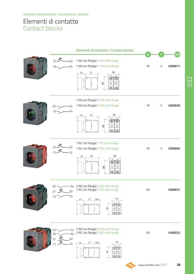
Elementi di contatto Contact blocks
1 NC con flangia / 1NC with flange
1 NO con flangia / 1NO with flange 19 5 020GE11
1 NO con flangia / 1NO with flange
1 NO con flangia / 1NO with flange 19 5 020GE20
1 NC con flangia / 1NC with flange
1 NC con flangia / 1NC with flange 19 5 020GE02
2 NO con flangia / 2NO with flange 2 NC con flangia / 2NC with flange 50 020GE22
2 NO con flangia / 2NO with flange 1 NC con flangia / 1NC with flange 50 020GE21
13
13
23
14
1424
21 22
11 12
21 22
Elementi di contatto / Contact blocks
24 37
38
30= =
24 37
38
30= =
24 37
38
30= =
24
38
30= =
37 18,5
24
38
30= =
37 18,5
12
14
22
22
11
13
21
21
34
34
4433
33
43
COMANDO E SEGNALAZIONE - FILO PANNELLO SM2 Ø 30
29 032 | www.newelfin.com
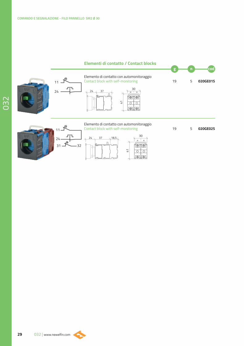
Elemento di contatto con automonitoraggio Contact block with self-monitoring 19 5 020GE01S
Elemento di contatto con automonitoraggio Contact block with self-monitoring 19 5 020GE02S
11
11
24
24
31 32
Elementi di contatto / Contact blocks
2430
= =
41
37
2430
= =
41
37 18,5
30www.newelfin.com | 032
COMANDO E SEGNALAZIONE - FILO PANNELLO SM2 Ø 30
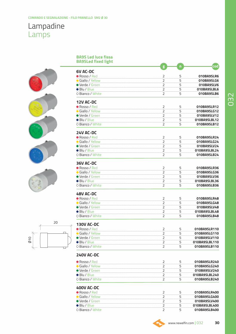
Lampadine Lamps
6V AC-DC Rosso / Red 2 5 010BA9SLR6 Giallo / Yellow 2 5 010BA9SLG6 Verde / Green 2 5 010BA9SLV6 Blu / Blue 2 5 010BA9SLBL6 Bianco / White 2 5 010BA9SLB6
12V AC-DC Rosso / Red 2 5 010BA9SLR12 Giallo / Yellow 2 5 010BA9SLG12 Verde / Green 2 5 010BA9SLV12 Blu / Blue 2 5 010BA9SLBL12 Bianco / White 2 5 010BA9SLB12
24V AC-DC Rosso / Red 2 5 010BA9SLR24 Giallo / Yellow 2 5 010BA9SLG24 Verde / Green 2 5 010BA9SLV24 Blu / Blue 2 5 010BA9SLBL24 Bianco / White 2 5 010BA9SLB24
36V AC-DC Rosso / Red 2 5 010BA9SLR36 Giallo / Yellow 2 5 010BA9SLG36 Verde / Green 2 5 010BA9SLV36 Blu / Blue 2 5 010BA9SLBL36 Bianco / White 2 5 010BA9SLB36
48V AC-DC Rosso / Red 2 5 010BA9SLR48 Giallo / Yellow 2 5 010BA9SLG48 Verde / Green 2 5 010BA9SLV48 Blu / Blue 2 5 010BA9SLBL48 Bianco / White 2 5 010BA9SLB48
130V AC-DC Rosso / Red 2 5 010BA9SLR110 Giallo / Yellow 2 5 010BA9SLG110 Verde / Green 2 5 010BA9SLV110 Blu / Blue 2 5 010BA9SLBL110 Bianco / White 2 5 010BA9SLB110
240V AC-DC Rosso / Red 2 5 010BA9SLR240 Giallo / Yellow 2 5 010BA9SLG240 Verde / Green 2 5 010BA9SLV240 Blu / Blue 2 5 010BA9SLBL240 Bianco / White 2 5 010BA9SLB240
400V AC-DC Rosso / Red 2 5 010BA9SLR400 Giallo / Yellow 2 5 010BA9SLG400 Verde / Green 2 5 010BA9SLV400 Blu / Blue 2 5 010BA9SLBL400 Bianco / White 2 5 010BA9SLB400
BA9S Led luce fissa BA9SLed fixed light
20
Ø10
COMANDO E SEGNALAZIONE - FILO PANNELLO SM2 Ø 30
31 032 | www.newelfin.com
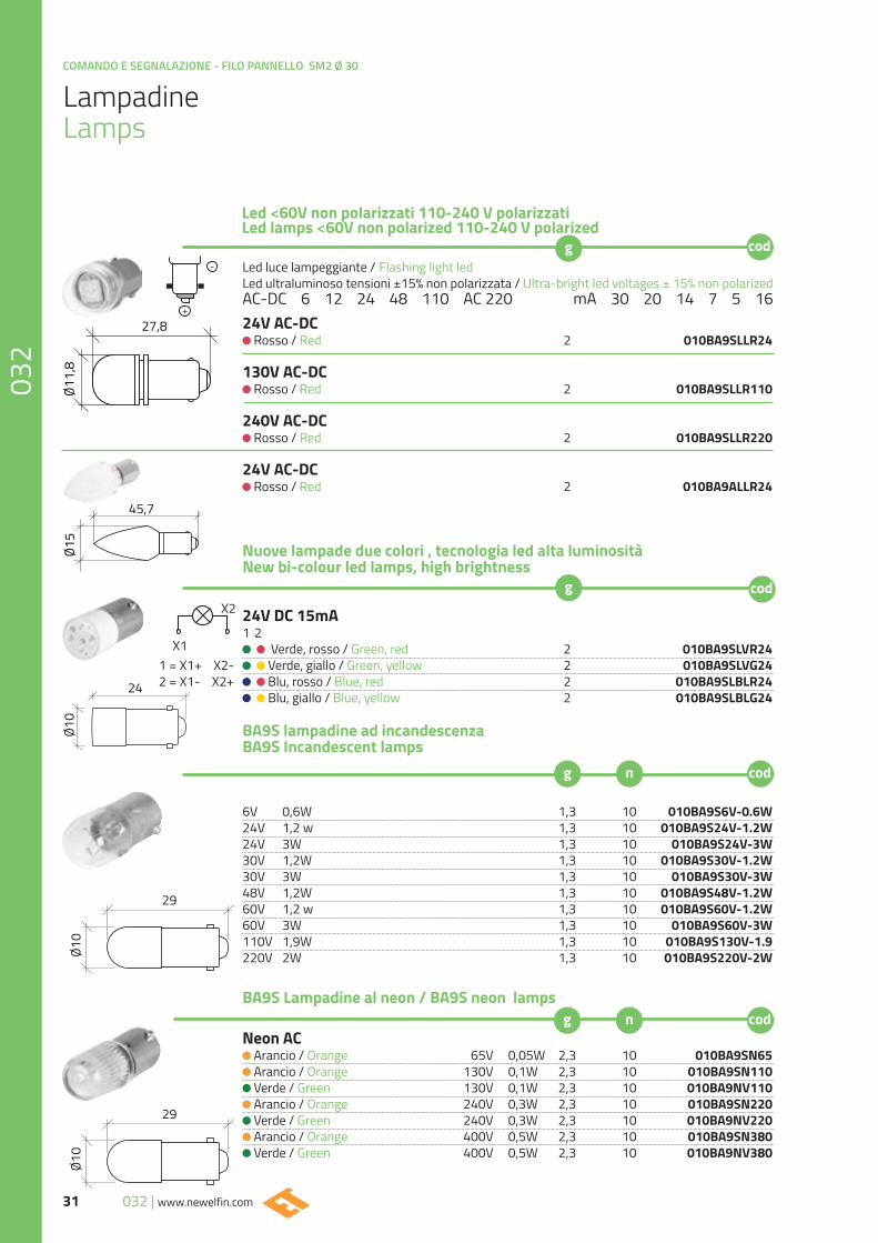
Lampadine Lamps
Led luce lampeggiante / Flashing light ledLed ultraluminoso tensioni ±15% non polarizzata / Ultra-bright led voltages ± 15% non polarizedAC-DC 6 12 24 48 110 AC 220 mA 30 20 14 7 5 1624V AC-DC
Rosso / Red 2 010BA9SLLR24
130V AC-DC Rosso / Red 2 010BA9SLLR110
240V AC-DC Rosso / Red 2 010BA9SLLR220
24V AC-DC Rosso / Red 2 010BA9ALLR24
Nuove lampade due colori , tecnologia led alta luminositàNew bi-colour led lamps, high brightness
24V DC 15mA1 2
Verde, rosso / Green, red 2 010BA9SLVR24 Verde, giallo / Green, yellow 2 010BA9SLVG24 Blu, rosso / Blue, red 2 010BA9SLBLR24 Blu, giallo / Blue, yellow 2 010BA9SLBLG24
Led <60V non polarizzati 110-240 V polarizzati Led lamps <60V non polarized 110-240 V polarized
X1
X2
1 = X1+ X2-2 = X1- X2+
6V 0,6W 1,3 10 010BA9S6V-0.6W24V 1,2 w 1,3 10 010BA9S24V-1.2W24V 3W 1,3 10 010BA9S24V-3W30V 1,2W 1,3 10 010BA9S30V-1.2W30V 3W 1,3 10 010BA9S30V-3W48V 1,2W 1,3 10 010BA9S48V-1.2W60V 1,2 w 1,3 10 010BA9S60V-1.2W60V 3W 1,3 10 010BA9S60V-3W110V 1,9W 1,3 10 010BA9S130V-1.9220V 2W 1,3 10 010BA9S220V-2W
BA9S Lampadine al neon / BA9S neon lamps
Neon AC Arancio / Orange 65V 0,05W 2,3 10 010BA9SN65 Arancio / Orange 130V 0,1W 2,3 10 010BA9SN110 Verde / Green 130V 0,1W 2,3 10 010BA9NV110 Arancio / Orange 240V 0,3W 2,3 10 010BA9SN220 Verde / Green 240V 0,3W 2,3 10 010BA9NV220 Arancio / Orange 400V 0,5W 2,3 10 010BA9SN380 Verde / Green 400V 0,5W 2,3 10 010BA9NV380
BA9S lampadine ad incandescenzaBA9S Incandescent lamps
29
Ø10
29
Ø10
24
Ø10
27,8
Ø11,
8
45,7
Ø15
32www.newelfin.com | 032
COMANDO E SEGNALAZIONE - FILO PANNELLO SM2 Ø 30