Embed Size (px)
Citation preview
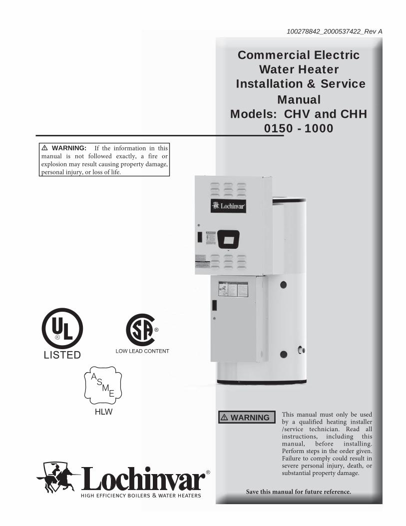
Commercial Electric Water Heater
Installation & Service Manual
Models: CHV and CHH 0150 - 1000
This manual must only be used by a qualified heating installer /service technician. Read all instructions, including this manual, before installing. Perform steps in the order given. Failure to comply could result in severe personal injury, death, or substantial property damage.
� WARNING
Save this manual for future reference.
100278842_2000537422_Rev A
� WARNING: If the information in this manual is not followed exactly, a fire or explosion may result causing property damage, personal injury, or loss of life.
HLW
2
Hazard definitionsThe following defined terms are used throughout this manual to bring attention to the presence of hazards of various risk levels or to important information concerning the life of the product.
� DANGER
� WARNING
� CAUTION
CAUTION
NOTICE
DANGER indicates an imminently hazardous situation which, if not avoided, will result in death or serious injury.
WARNING indicates a potentially hazardous situation which, if not avoided, could result in death or serious injury.
CAUTION indicates a potentially hazardous situation which, if not avoided, may result in minor or moderate injury.
CAUTION used without the safety alert symbol indicates a potentially hazardous situation which, if not avoided, may result in property damage.NOTICE indicates special instructions on installation, operation, or maintenance that are important but not related to personal injury or property damage.
HAZARD DEFINITIONS .................................................... 2PLEASE READ BEFORE PROCEEDING ........................ 3INTRODUCTION ................................................................ 4RATINGS ........................................................................... 51. FEATURES AND COMPONENTSCHV Models (Vertical Water Heater) ................................. 6CHH Models (Horizontal Water Heater) ............................. 7Dimensions and Capacities Data ................................... 8-92. DETERMINE WATER HEATER LOCATIONFacts to Consider About the Location ......................... 10-113. INSTALLATIONMixing Valve Usage ......................................................... 12Chemical Vapor Corrosion ............................................... 12Circulating Pump .............................................................. 12Insulation Blankets .......................................................... 12Temperature - Pressure Relief Valve ...........................12-13Closed Water Systems ...................................................... 13Thermal Expansion .......................................................... 134. ELECTRICALGeneral ............................................................................. 14Branch Circuit ................................................................... 14Heater Circuits.................................................................. 14Power Circuit .................................................................... 14Amp Chart ................................................................... 15-16Electrical and Recoveries Data ................................... 17-185. OPERATIONGeneral ............................................................................. 19Filling the Water Heater ................................................... 19Initial Start-up ................................................................... 19Draining the Water Heater ............................................... 196. TEMPERATURE REGULATIONHigh Temperature Limit Controls (ECO) .......................... 20Thermostat Controls ......................................................... 20Temperature Adjustment .................................................. 20
7. CONTROL SYSTEM OPERATIONHeating Banks Operation ................................................. 21Control System Features ................................................. 21Control System Navigation ............................................... 21The Display Screen .......................................................... 21Control System Operation Tables ............................... 22-23Temperatures Menu ......................................................... 24Temperature Screens ...................................................... 25Water Heater Status Menu .............................................. 26Economy Mode Setup Menu ............................................ 27Economy Mode Settings Tables ................................. 28-30Alarm Output Setup Menu ............................................... 31Display Settings Menu ..................................................... 31Heater Information Menu ................................................. 32Current Fault / Alert Menu ................................................ 32Fault History Menu ........................................................... 32Fault Occurrence Menu .................................................... 33Restore Factory Defaults Menu ....................................... 348. MAINTENANCEGeneral ............................................................................. 35Anode Rod Inspection ...................................................... 35Flushing the Water Heater ............................................... 35Sediment Removal ........................................................... 36Lime Scale Removal ........................................................ 369. TROUBLESHOOTINGChecklist ........................................................................... 3710. DIAGRAMSWiring Diagram .......................................................... 38-39Revision Notes .................................................. Back Cover
Contents
Please read before proceedingInstaller – Read all instructions before installing. Perform steps in the order given.
Have this water heater serviced/inspected by a qualified service technician, at least annually.
Failure to comply with the above could result in severe personal injury, death, or substantial property damage.
Failure to adhere to the guidelines on this page can result in severe personal injury, death, or substantial property damage.
When servicing the water heater –
• To avoid electric shock, disconnect electrical supply before performing maintenance.
• To avoid severe burns, allow the water heater to cool before performing maintenance.
• Do not use this water heater if any part has been under water. The possible damage to a flooded appliance can be extensive and present numerous safety hazards. Any appliance that has been under water must be replaced.
When calling or writing about the water heater – Please have the water heater model and serial number from the water heater rating plate.
Consider piping and installation when determining water heater location.
Any claims for damage or shortage in shipment must be filed immediately against the transportation company by the consignee.
Factory warranty (shipped with unit) does not apply to units improperly installed or improperly operated.
3
� WARNING
NOTICE
� WARNING
� WARNING If the information in this manual is not followed exactly, a fire or explosion may result causing property damage, personal injury, or loss of life.
� WARNING The California Safe Drinking Water and Toxic Enforcement Act requires the Governor of California to publish a list of substances known to the State of California to cause cancer, birth defects, or other reproductive harm, and requires businesses to warn of potential exposure to such substances.This product contains a chemical known to the State of California to cause cancer, birth defects, or other reproductive harm. This water heater can cause low level exposure to some of the substances listed in the Act.
Grounding Instructions –
• This water heater must be grounded in accordance with the National Electrical Code and/or local codes. These must be followed in all cases. Failure to ground this water heater properly may also cause erratic control system operation on ELECTRONIC CONTROL models.
• This water heater must be connected to a grounded metal, permanent wiring system, or an equipment grounding conductor must be run with the circuit conductors and connected to the equipment grounding terminal or lead on the water heater.
Installation & Operation Manual
Hydrogen Gas (Flammable) –
Hydrogen gas can be produced in a hot water system, served by this heater, that has not been used for a long period of time (generally two weeks or more). Hydrogen gas is extremely flammable. To reduce the risk of injury, it is recommended that the hot water faucet be opened for several minutes at the kitchen sink before using any electrical appliance connected to the hot water system. If hydrogen is present, there will probably be an unusual sound, such as air escaping through the pipe as water begins to flow.
� WARNING There should be no smoking or open flame near the faucet at the time it is open.
� WARNING Flammable hydrogen gases may be present.
� WARNING Keep all ignition sources away from faucet when turning on hot water.
4
IntroductionTh ank you for purchasing this water heater. Properly installed and maintained, it should give you years of trouble-free service.
Abbreviations found in this instruction manual include:• ANSI - American National Standards Institute• ASME - American Society of Mechanical Engineers• NEC - National Electrical Code• NFPA - National Fire Protection Association• UL - Underwriters Laboratory• CSA - Canadian Standards Association• AHRI - Air Conditioning, Heating, & Refrigeration
Institute
Abbreviations Used
Preparing for the Installation
� WARNING Before removing any access panels or servicing the water heater, make sure the electrical supply to the water heater is turned OFF. Failure to do this could result in death, serious bodily injury, or property damage.
Read the Please read before proceeding... section of this manual fi rst, then read the entire manual carefully. If you don’t follow the safety rules, the water heater may not operate safely, which could result in death, serious bodily injury, and/or property damage.
Th is manual contains instructions for the installation, operation, and maintenance of the water heater. It also contains warnings throughout the manual that you must read and be aware of. All warnings and all instructions are essential to the proper operation of the water heater and your safety. Read the entire manual before attempting to install or operate the water heater.
General outline diagrams are in this manual. Th ese diagrams will serve to provide the installer with a reference for basic installation of this product. It is necessary that all water piping and electrical wiring be installed and connected as shown in the diagrams.
Be sure to turn power OFF when working on or near the electrical system of the water heater. Never touch electrical components with wet hands or when standing in water. When replacing fuses always use the correct size for the circuit. Use the same size and type of fuse when replacing.
Detailed installation diagrams are in this manual. Th ese diagrams will serve to provide the installer with a reference for the materials and method of piping suggested. It is necessary that all water piping and electrical wiring be installed and connected as shown in the diagrams.
Th e principle components of the heater are identifi ed on pages 6 and 7. Th e model and rating plate on page 5 interprets certain markings into useful information. Both of these references should be used to identify the heater, its components, and optional equipment.
Th e installation must conform with these instructions and the local code authority having jurisdiction and the requirements of the power company. In the absence of local codes, the installation must comply with the current editions of the National Electrical Code, NFPA 70 or the Canadian Electrical Code, CSA C22.1. Th e National Electrical Code may be ordered from: National Fire Protection Association, 1 Batterymarch Park, Quincy, MA 02269. Th e Canadian Electrical Code is available from the Canadian Standards Association, 8501 East Pleasant Valley Road, Cleveland, OH 44131.
If aft er reading this manual you have any questions or do not understand any portion of the instructions, call the telephone number on the back cover for further assistance. Please have the model and serial number of the unit available for the technician.
Carefully plan your intended placement of the water heater. Examine the location to ensure the water heater complies with the Determine Water Heater Location section in the manual.
Clearance must be maintained so that the heating elements may be removed for servicing aft er installation.
Installation and service of this water heater requires ability equivalent to that of a licensed tradesman or qualifi ed agency in the fi eld involved. Plumbing and electrical work are required.
For installation in California, this water heater must be braced or anchored to avoid falling or moving during an earthquake. See instructions for correct installation procedures. Instructions may be obtained from the California Offi ce of the State Architect, 1102 Q Street, Suite 5100, Sacramento, CA 95811.
Massachusetts Code requires this water heater to be installed in accordance with Massachusetts 248-CMR 2.00: State Plumbing Code and 248-CMR 5.00.
Installation & Operation Manual
5
HLW
Ratings
All models are listed by Underwriters Laboratories Inc.
Rating & Model Plate
L
LISTED932N
®
SERIAL NUMBER ITEM ID/PART NUMBERMODEL NUMBER
PHASEVOLTS, AC UPPERKILOWATTS
LOWERKILOWATTS
CONNECTEDTOTAL kW
ELECTRIC STORAGETANK WATER HEATER
US GALLONSCAPACITY
PRESSUREMAX WORKING
VOLTS, AC UPPERKILOWATTS
LOWERKILOWATTS
CONNECTEDTOTAL kW
CIRCUIT
SERIAL NUMBER BARCODE
SERIAL NUMBER
MODEL NUMBER BARCODE
MODEL NUMBER
ADDRESS
XXXXXXXX 123456789
ASME
HLW
123456
S/N123456789
CERTIFIED BY LCMAWP XXX PSIMAX ALLOWABLE INPUTXXXXXXXXX BTU/HR
CRN XXXXXXXXXXXXXXXXXXXXYEAR BUILT YYWW
Installation & Operation Manual
6
1 Features and ComponentsCHV Models (Vertical Water Heater)
Note: Model shown for illustration purposes only. Actual confi gurations may vary.
Installation & Operation Manual
7
LOW VOLTAGE FUSE & BLOCK
HIGH LIMIT
LOW VOLTAGE GROUND LUG
MAIN VOLTAGE TRANSFORMER
ELEMENTS
LOW VOLTAGE FUSE & BLOCK
RELIEF VALVE
ANODE
POWER BLOCK
MAIN VOLTAGE GROUND LUG
MAIN VOLTAGE FUSE & BLOCK
CONTACTORS
TEMPERATURE PROBE
PLUG
HANDHOLE/MANWAYACCESS
LOW WATER CUT OFF PROBE
CONTROLLER
TRANSFORMER (CONTROLLER)
CHH Models (Horizontal Water Heater)
1 Features and Components
Note: Model shown for illustration purposes only. Actual confi gurations may vary.
Installation & Operation Manual
8
1 Features and Components (continued)
Specifications Data
Installation & Operation Manual
RELIEF
CLEANOUT COLD WATER
ADDITIONAL OUTLET
REQUIREDHEIGHT IF
VALVE CONNECTION
HOT WATER
INLET
DRAIN
3/4"T & P
CONTROL VOLTAGEON/OFF SWITCH
CHANNEL (HV* 150 & HV* 200 DO NOT HAVE CHANNEL)
B
A
D
3/4" OR 1" DRAIN
HINGED DOORTO ELECTRICAL COMPARTMENT
TOP VIEW
C
ELECTRONIC CONTROL
C 6.688
HIGHER THAN 72KW. CONSULT FACTORY.
INLET
EXTRA PANEL BOX MAY BE NECESSARY FOR INPUTS
DRAIN
A & D ELEVATION FROM FINISHED FLOOR
OUTLETHOT WATER T&P RELIEF VALVE
4.000
D
B
ELECTRONICCONTROL
CONTROL VOLTAGEON/OFF SWITCH
HEIGHT IF REQUIRED
ADDITIONAL
HANDHOLE
Model* Maximum KWInput
HeightA
Width(Length)
B
DepthC D
InletWater
Connection
Outlet Water Connection
Shipping Weight (lbs)
VERTICAL ROUND ELECTRIC STORAGE HEATER
CHV0150 162 65 1/2" 32" 38 3/4" 8 1/4" 1 1/2" 1 1/2" 650
CHV0200 216 78" 32" 38 3/4" 8 1/4" 1 1/2" 1 1/2" 750
CHV0250 270 91 3/8" 34" 40 3/4" 19 1/4" 1 1/2" 1 1/2" 1,165
CHV0300 162 80" 40" 46 3/4" 20 3/4" 2" 2" 1,350
CHV0400 162 80" 46" 52 3/4" 22 1/4" 2" 2" 1,590
CHV0500 270 91 3/8" 46" 52 3/4" 22 1/4" 2" 2" 1,700
CHV0600 270 92 5/8" 52" 58 3/4" 24 1/4" 2 1/2" 2 1/2" 2,010
CHV0800 432 104" 52" 58 3/4" 24 1/4" 2 1/2" 2 1/2" 2,450
CHV1000 486 128" 52" 58 3/4" 24 1/4" 2 1/2" 2 1/2" 3,160
VERTICAL SQUARE ELECTRIC STORAGE HEATER
CHV1250 648 132 1/2" 64 1/2" 64 1/2" 23 1/4" 3" 3" 3,560
CHV1500 918 128 1/2" 70 1/2" 70 1/2" 25 1/4" 3" 3" 4,120
CHV2000 918 140 1/2" 76 1/2" 76 1/2" 27 1/4" 3" 3" 4,350
CHV2500 918 146 1/2" 82 1/2" 82 1/2" 29" 3" 3" 5,750
HORIZONTAL SQUARE ELECTRIC STORAGE HEATER
CHH0150 162 37" 68 1/2" 34 1/4" 12" 2" 2" 1,180
CHH0200 198 37" 78" 34 1/4" 12" 2" 2" 1,370
CHH0250 240 39" 90 1/4" 36 1/4" 13" 2" 2" 1,450
CHH0300 300 45" 78 1/4" 42 1/4" 14 3/4" 2" 2" 1,530
CHH0400 324 52" 78 1/4" 48 1/4" 16" 2" 2" 1,750
CHH0500 432 52" 90 3/4" 48 1/4" 16" 2" 2" 1,860
CHH0600 414 58" 90 3/4" 54 1/4" 13 1/2" 2 1/2" 2" 2,340
CHH0800 468 58" 102 1/4" 54 1/4" 13 1/2" 2 1/2" 2" 2,850
CHH1000 648 58" 126 1/4" 54 1/4" 13 1/2" 2 1/2" 2" 3,040
CHH1250 648 64" 130 1/4" 60 1/4" 15" 3" 3" 3,750
CHH1500 918 70" 126 1/4" 66 1/4" 16" 3" 3" 4,340
CHH2000 918 76" 137 1/4" 72 1/4" 17 1/2" 3" 3" 4,580
CHH2500 918 82" 144 1/4" 78 1/4" 16 1/2" 3" 3" 6,060
1 Features and Components (continued)
Specifications Data (continued)
Installation & Operation Manual
9
CONTROL
BOARD WITH
DISPLAY
HI-POWER
VERTICAL
VOLTAGE
KILOWATT
GALLON
C H V X 072 0250
This unit is a Control Board with Display, Hi-Power, Vertical, 480 Volt,Three Phase, 72 Kilowatt, 250 Gallon Water Heater.
FOR EASE IN ORDERING
BY MODEL NUMBER
10
2 Determine Water Heater Location
Determine Water Heater LocationAll water heaters eventually leak. Do not install without adequate drainage. CAUTION
Carefully choose a location for the new water heater. Th e placement is a very important consideration for the safety of the occupants in the building and for the most economical use of the appliance.Whether replacing an old water heater or putting the water heater in a new location, the following critical points must be observed. Th e water heater must be located:
1. On a level surface. Shim the channel-type skid base as necessary if leveling is required.
2. Near a fl oor drain. Th e heater should be located in an area where leakage of the tank or connections will not result in damage to the area adjacent to the heater or to lower fl oors of the structure. When such locations cannot be avoided, a suitable drain pan should be installed under the heater. Th e pan should be at least 2 inches deep, have a minimum length and width of at least 2 inches greater than the dimensions of the water heater, and should be piped to an adequate drain. Th e discharge opening of the relief valve should always be piped to an open drain.
3. Close to the point of major hot water usage and the power supply.
Installation & Operation Manual
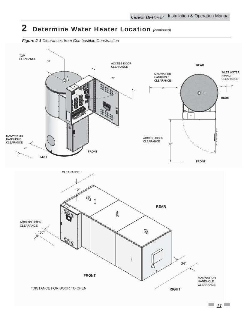
Hot water piping and branch circuit wiring should be as short as possible. Insulate hot and cold water piping where heat loss and condensation may be a problem. Heater construction permits installation, maintenance, and service work to be performed through the element box door and control box door.Suggested clearances from adjacent surfaces are 12 inches on top, 30 inches in front of access doors, 24 inches for cleanout/handhole/manway side, and 6 inches on the inlet water piping side.Th e heater may be installed on or against combustible surfaces. Th e back may be placed fl ush against adjacent surfaces. Be sure to place the cover plates over the rear crating couplings before locating vertical model heaters that were shipped laying down. Th e heater may be installed in a confi ned space if adequate ventilation is provided.Th e temperature of the space in which the water heater is installed must not go below 320F or above 1220F.
2 Determine Water Heater Location (continued)
Installation & Operation Manual
24"
36"
6"
FRONT←
REAR
←
RIGHT
12"
←
LEFT
←
←24"
←
FRONT
30"
MANWAY ORHANDHOLE CLEARANCE
TOPCLEARANCE
ACCESS DOOR CLEARANCE
ACCESS DOOR CLEARANCE
MANWAY ORHANDHOLE CLEARANCE
INLET WATER PIPING CLEARANCE
↓12"
FRONT
REAR
24"
↓
↓
↓
↓
↓
*30"
ACCESS DOOR CLEARANCE
MANWAY ORHANDHOLE CLEARANCE
CLEARANCE
*DISTANCE FOR DOOR TO OPEN RIGHT
Figure 2-1 Clearances from Combustible Construction
11
12
3 InstallationTh e installation must conform to these instructions and local code authority having jurisdiction. Grounding and electrical wiring connected to the water heater must also conform to the National Electrical Code, NFPA 70. Th is publication is available from Th e National Fire Protection Association, 1 Batterymarch Park, Quincy, MA 02269.
� DANGER Water temperature over 1250F (520C) can cause severe burns instantly resulting in severe injury or death. Children, the elderly, and the physically or mentally disabled are at highest risk for scald injury. Feel water before bathing or showering. Temperature limiting devices, such as mixing valves, must be installed when required by code and to ensure safe temperatures at fixtures.
Mixing Valve UsageWater heaters are intended to produce hot water. Water heated to a temperature which will satisfy clothes washing, dish washing, cleaning, and other sanitizing needs can scald and permanently injure you upon contact. Some people are more likely to be permanently injured by hot water than others. Th ese include the elderly, children, the infi rm, or the physically or developmentally disabled. If anyone using hot water in your home fi ts into one of these groups, or if there is a local code or state law requiring a maximum water temperature at the hot water tap, then you must take special precautions. In addition to using the lowest possible temperature setting that satisfi es your hot water needs, a means such as a mixing valve, should be used at the hot water taps or at the water heater.Mixing valves for reducing point-of-use temperature are available. Consult a qualifi ed installer or service agency. Follow all manufacturer’s instructions for installation of mixing valves. Before changing the factory setting on the thermostat, read the Temperature Regulation section in this manual.
� WARNING Toxic chemical hazard: Do not connect to non-potable water system.
Chemical Vapor CorrosionTh is water heater shall not be connected to any heating system(s) or component(s) used with a non-potable water heating appliance. Toxic chemicals, such as those used for boiler treatment, shall not be introduced into this system. Water heater corrosion and component failure can be caused by the heating and breakdown of airborne chemical vapors. Spray can propellants, cleaning solvents, refrigerator and air conditioning refrigerants, swimming pool chemicals, water soft ener chemicals, calcium and sodium chloride, waxes, and process chemicals are typical
Circulating PumpField-installed circulating pumps should be of all bronze constructions. To optimize the total storage capacity of a horizontal vessel, particularly under low draw conditions, it is recommended to utilize a pump and recirculation line sized to turn the entire storage capacity of the tank once each hour (i.e., a 600 gallon tank would require a 10 gpm pump).
Insulation BlanketsInsulation blankets are available to the general public for external use on electric water heaters, but are not necessary with this product. Th e purpose of an insulation blanket is to reduce the standby heat loss encountered with storage tank heaters. Your water heater meets or exceeds the EPACT and ASHRAE/IES 90.1 standards with respect to insulation and standby loss requirements, making an insulation blanket unnecessary.Should you choose to apply an insulation blanket to this heater, you should follow the instructions below. Failure to follow these instructions can result in fi re, serious personal injury, or death.• Do NOT cover the temperature and pressure relief (T & P)
valve with an insulation blanket.• Do NOT cover the instruction manual. Keep it on the side
of the water heater or nearby for future reference.• DO obtain new warning and instruction labels for placement
on the blanket directly over the existing labels.
compounds which are potentially corrosive. Th ese materials are corrosive at very low concentration levels with little or no odor to reveal their presence. Products of this sort should not be stored near the heater. Also, air which is brought in contact with the water heater should not contain any of these chemicals. If necessary, uncontaminated air should be obtained from remote or outside sources.
� WARNING The temperature and pressure relief valve must comply with ANSI Z21.22 and ASME code. A properly sized temperature and pressure relief valve must be installed in the opening provided. Failure to install a relief valve can result in overheating and excessive tank pressure. Failure to follow these instructions can cause serious injury or death.
Temperature - Pressure Relief Valve
Th is water heater is provided with a properly rated/sized and certifi ed combination temperature-pressure relief valve by the manufacturer. Th e valve is certifi ed by a nationally recognized testing laboratory that maintains periodic inspection of production of listed equipment of materials as meeting the requirements for Relief Valves for Hot Water Supply Systems, ANSI Z21.22 • CSA 4.4, and the code requirements of ASME.
Installation & Operation Manual
CAUTION Do NOT test electrical system before heater is fi lled with water. Follow the Start-up procedure in the Operation section of this manual.
Th e principle components of the heater are identifi ed in the Features and Components illustration on pages 6 and 7.
Installation & Operation Manual
13
3 Installation (continued)
CAUTION The temperature-pressure relief valve discharge pipe must terminate at adequate drain.
Th e discharge pipe:• Shall NOT be smaller in size than the outlet pipe size of the
valve or have any reducing couplings or other restrictions.• Shall NOT be plugged or blocked.• Shall NOT be exposed to freezing temperatures.• Shall be of material listed for hot water distribution.• Shall be installed in such a way that allows complete
drainage of both the temperature-pressure relief valve and the discharge pipe.
• Must terminate a maximum of six inches above a fl oor drain or external to the building. In cold climates, it is recommended that the discharge pipe be terminated at an adequate drain inside the building.
• Shall NOT have any valve or other obstruction between the relief valve and the drain.
Th e temperature-pressure relief valve must be manually operated at least once a year. Caution should be taken to ensure that no one is in front of or around the outlet of the temperature-pressure relief valve discharge line, and that the water manually discharged will not cause any bodily injury or property damage because the water may be extremely hot. If aft er manually operating the valve, it fails to completely reset and continues to release water, immediately close the cold water inlet to the water heater, follow the draining instructions in this manual, and replace the temperature-pressure relief valve with a properly rated/sized new one. If you do not understand these instructions or have any questions regarding the temperature-pressure relief valve, call the telephone number listed on the back cover of this manual for technical assistance.
� DANGER Water temperature over 1250F (520C) can cause severe burns instantly resulting in severe injury or death. Children, the elderly, and the physically or mentally disabled are at highest risk for scald injury. Feel water before bathing or showering. Temperature limiting devices, such as mixing valves, must be installed when required by code and to ensure safe temperatures at fixtures. Read instruction manual for safe temperature setting.
Closed Water SystemsWater supply systems may, because of code requirements or such conditions as high line pressure, among others, have installed devices such as pressure reducing valves, check valves, and back fl ow preventers. Devices such as these cause the water system to be a closed system.
Thermal ExpansionAs water is heated, it expands (thermal expansion). In a closed system, the volume of water will grow when it is heated. As the volume of water grows, there will be a corresponding increase in water pressure due to thermal expansion. Th ermal expansion can cause premature tank failure (leakage). Th is type of failure is not covered under the limited warranty. Th ermal expansion can also cause intermittent temperature-pressure relief valve operation, water discharged from the valve due to excessive pressure build-up. Th is condition is not covered under the limited warranty. Th e temperature-pressure relief valve is not intended for the constant relief of thermal expansion.A properly sized thermal expansion tank must be installed on all closed systems to control the harmful eff ects of thermal expansion. Contact a local plumbing service agency to have a thermal expansion tank installed.
If replaced, the new valve must meet the requirements of local codes, but not less than a combination temperature and pressure relief valve rated/sized and certifi ed as indicated in the above paragraph. Th e new valve must be marked with a maximum set pressure not to exceed the marked hydrostatic working pressure of the water heater (150 psi = 1,035 kPa) and a discharge capacity not less than the water heater Btu/hr or KW input rate as shown on the water heater’s model rating plate.For safe operation of the water heater, the temperature and pressure relief valve must not be removed from its designated opening nor plugged. Th e temperature-pressure relief valve must be installed directly into the fi tting of the water heater designed for the relief valve. Install discharge piping so that any discharge will exit only within 6 inches (15.2 cm) above, or external to the structure. Do not pipe the discharge to a crawl space. Be certain that no contact is made with any live electrical part. Th e discharge opening must not be blocked or reduced in size under any circumstances. Excessive length, over 30 feet (9.14 m), or use of more than four elbows can cause restriction and reduce the discharge capacity of the valve.No valve or other obstruction is to be placed between the relief valve and the tank. Do NOT connect discharge piping directly to the drain unless a 6" (15.2 cm) air gap is provided. To prevent bodily injury, hazard to life, or property damage, the relief valve must be allowed to discharge water in adequate quantities, should circumstances demand. If the discharge pipe is not connected to a drain or other suitable means, the water fl ow may cause property damage.
14
4 Electrical
Check the water heater model and rating plate information against the characteristics of the branch circuit electrical supply. Do NOT connect the heater to an improper source of electricity.Voltage applied to the heater should not vary more than +5% to -10% of the model and rating plate marking for satisfactory operation.Th e factory wiring is attached to a terminal block on the unit. Th e branch circuit is connected to the block through an opening provided on the heater. Th e factory terminal block has 500 MCM maximum copper wire size capacity in each opening. If apparent fi eld wire size is over 500 MCM, multiple terminal blocks will be furnished. If other opening sizes are desired, they should be specifi ed when the unit is ordered.Th e installation must conform with these instructions and the local code authority having jurisdiction and the requirements of the power company. In the absence of local codes, the installation must comply with the current editions of the National Electrical Code, NFPA 70, or the Canadian Electrical Code CSA C22.1.
General
Branch CircuitTh e branch circuit wire size should be established through reference to the NEC (National Electrical Code) or other locally approved sources in conjunction with the water heater amperage rating. Wire rated at 75°C should be used. Please see Table 4-1 for additional information. It is suggested that the electrician size the branch circuit at 125% of the heater rating and further increase wire size as necessary to compensate for voltage drop in long runs. Voltage drop should not exceed 3% at the water heater.
Heater CircuitsTh e water heater’s electrical components are pictured and identifi ed by the Features and Components illustrations on pages 6 and 7. Th e model and rating plate illustration identifi es the heater electrical characteristics. Th e heater has two electrical circuits.• Control Circuit: 120V circuit containing all safety and
control devices. Th e control circuit operates the contactors in the power circuit.
• Power Circuit: High voltage, single or three-phase circuit that carries the heating element load.
Th e following section and pages describe the water heater circuits. See pages 38 - 39 for the wiring diagram.
Installation & Operation Manual
Power CircuitPower circuit wiring is type THHN (or equivalent) rated 600 volts, 105°C, sized as necessary.Th e wiring diagrams at the end of this manual are included to show typical arrangements of electrical components in the control and power circuits by voltage and phase characteristics. Th ey are to be used as a reference by the installer or servicer in performing their work. An actual diagram of the water heater wiring is furnished with the heater.
Table 4-1 Amp Chart4 Electrical (continued)
Installation & Operation Manual
Total Ele. Total AMPS
Main Line Fuse
Field Wire Per Leg
KW KW Qnty Volt 10 30 10 30 10 3015 15 1 208
240380400415480600
7363**********
42362322211814
110110**********
60503030302520
34**********
68
1010101012
18 18 1 208240380400415480600
8775**********
50442726252217
110110**********
70603535353025
23**********
46888
1012
24 12 2 208240380400415480600
115100**********
67583635332923
150150**********
90805050504030
00**********
346668
1030 15 2 208
240380400415480600
145125**********
83724643423629
200175**********
1101006060605040
3/02/0**********
2266668
36 18 2 208240380400415480600
174150**********
100875552504335
225200**********
1501107070706045
4/03/0**********
0244468
45 15 3 208240380400415480600
217188**********
1251086865635443
300250**********
1751509090807060
300250**********
3/02/033446
54 18 3 208240380400415480600
260225**********
1501308278756552
350300**********
2001751101001009070
400350**********
4/03/022234
60 15 4 208240380400415480600
289250**********
1671449187837258
400350**********
22520012511011010080
500400**********
4/04/011224
Total Ele. Total AMPS
Main Line Fuse
Field Wire Per Leg
KW KW Qnty Volt 10 30 10 30 10 3072 18 4 208
240380400415480600
**************
2001731091041008769
**************
25022515015012511090
**************
2504/000123
90 15 6 208240380400415480600
**************
25021713713012510887
**************
350300175175175150110
**************
5003503/03/03/02/02
108 18 6 208240380400415480600
**************
300260164156150130104
**************
400350225200200175150
**************
(2) 3/05004/04/03/02/00
120 15 8 208240380400415480600
**************
333289182173167144115
**************
450400250225225200150
**************
(2) 4/0(2) 3/0
2502504/03/00
135 15 9 208240380400415480600
**************
375325205195188162130
**************
500450300250250225175
**************
(2) 250(2) 4/0
3503502504/02/0
144 18 8 208240380400415480600
**************
400346219208200173139
**************
500450300300250225175
**************
(2) 250(2) 4/0
3503002504/02/0
162 18 9 208240380400415480600
**************
450390246234225195156
**************
600500350300300250200
**************
(2) 350(2) 250
5003503502503/0
180 18 10 208240380400415480600
**************
500433273260250217173
**************
700600350350350300225
**************
(2) 500(2) 350
5005005003504/0
15
4 Electrical
Installation & Operation Manual
Total Ele. Total AMPS
Main Line Fuse
Field Wire Per Leg
KW KW Qnty Volt 10 30 10 30 10 30216 18 12 208
240380400415480600
**************
600520328312301260208
**************
800700450400400350300
**************
(3) 300(2) 500(2) 4/0(2) 3/0(2) 3/0
500350
234 18 13 208240380400415480600
**************
650563356338326281225
**************
1000800500450450400300
**************
(2) 400(2) 300(2) 250(2) 4/0(2) 4/0(2) 3/0
350252 18 14 208
240380400415480600
**************
694606383364351303242
**************
1000800500500450400350
**************
(3) 400(3) 300(2) 250(2) 4/0(2) 4/0(2) 3/0
500270 18 15 208
240380400415480600
**************
749650410390376325260
**************
10001000600500500450350
**************
(3) 400(3) 400(2) 350(2) 250(2) 250(2) 4/0
500288 18 16 208
240380400415480600
**************
799693438416401346277
**************
10001000600600600450350
**************
(3) 400(3) 400(2) 350(2) 350(2) 350(2) 4/0
500306 18 17 208
240380400415480600
**************
849736465442426368294
**************
12001000600600600500400
**************
(4) 350(3) 400(2) 350(2) 350(2) 350(2) 250(2) 3/0
324 18 18 208240380400415480600
**************
899779492468451390312
**************
12001000700600600500400
**************
(4) 350(3) 400(2) 500(2) 350(2) 350(2) 250(2) 3/0
342 18 19 208240380400415480600
**************
949823520494476411329
**************
12001200700700600600450
**************
(4) 350(4) 350(2) 500(2) 350(2) 350(2) 350(2) 4/2
Total Ele. Total AMPS
Main Line Fuse
Field Wire Per Leg
KW KW Qnty Volt 10 30 10 30 10 30360 18 20 208
240380400415480600
**************
999866547520501433346
**************
16001200700700700600450
**************
(5) 400(4) 350(2) 500(2) 500(2) 500(2) 350(2) 4/0
378 18 21 208240380400415480600
**************
1049909574546526455364
**************
16001200800700700600500
**************
(5) 400(4) 350(3) 300(2) 500(2) 500(2) 350(2) 250
396 18 22 208240380400415480600
**************
1099953602572551476381
**************
16001200800800700600500
**************
(5) 400(4) 350(3) 300(2) 500(2) 500(2) 350(2) 250
414 18 23 208240380400415480600
**************
1149996629598576498398
**************
16001600800800800700500
**************
(5) 400(5) 400(3) 300(3) 300(3) 300(2) 500(2) 250
432 18 24 208240380400415480600
**************
11991039656624601520416
**************
160016001000800800700600
**************
(5) 400(5) 400(3) 400(3) 300(3) 300(2) 500(2) 350
*CONSULT FACTORY FOR 432 KW AND HIGHER.
Table 4-1 Amp Chart (continued)
16
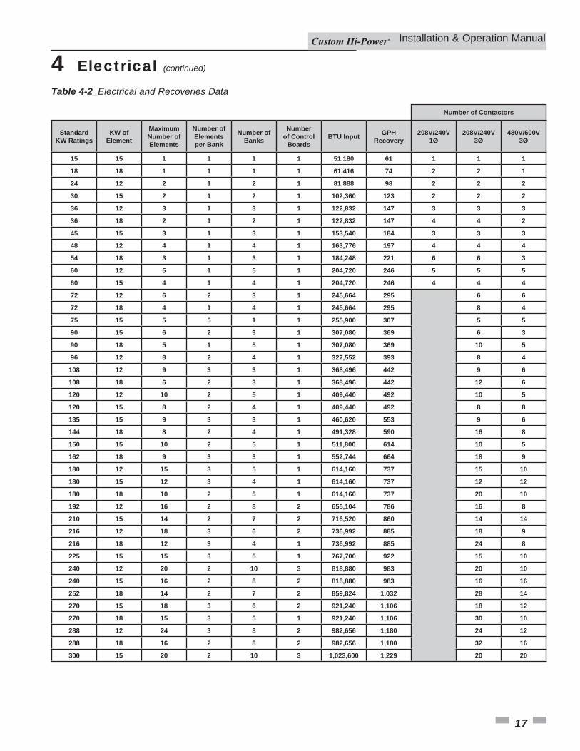
Table 4-2_Electrical and Recoveries Data
StandardKW Ratings
KW of Element
Maximum Number of Elements
Number of Elements per Bank
Number of Banks
Number of Control
BoardsBTU Input GPH
Recovery208V/240V
1Ø208V/240V
3Ø480V/600V
3Ø
15 15 1 1 1 1 51,180 61 1 1 1
18 18 1 1 1 1 61,416 74 2 2 1
24 12 2 1 2 1 81,888 98 2 2 2
30 15 2 1 2 1 102,360 123 2 2 2
36 12 3 1 3 1 122,832 147 3 3 3
36 18 2 1 2 1 122,832 147 4 4 2
45 15 3 1 3 1 153,540 184 3 3 3
48 12 4 1 4 1 163,776 197 4 4 4
54 18 3 1 3 1 184,248 221 6 6 3
60 12 5 1 5 1 204,720 246 5 5 5
60 15 4 1 4 1 204,720 246 4 4 4
72 12 6 2 3 1 245,664 295 6 6
72 18 4 1 4 1 245,664 295 8 4
75 15 5 5 1 1 255,900 307 5 5
90 15 6 2 3 1 307,080 369 6 3
90 18 5 1 5 1 307,080 369 10 5
96 12 8 2 4 1 327,552 393 8 4
108 12 9 3 3 1 368,496 442 9 6
108 18 6 2 3 1 368,496 442 12 6
120 12 10 2 5 1 409,440 492 10 5
120 15 8 2 4 1 409,440 492 8 8
135 15 9 3 3 1 460,620 553 9 6
144 18 8 2 4 1 491,328 590 16 8
150 15 10 2 5 1 511,800 614 10 5
162 18 9 3 3 1 552,744 664 18 9
180 12 15 3 5 1 614,160 737 15 10
180 15 12 3 4 1 614,160 737 12 12
180 18 10 2 5 1 614,160 737 20 10
192 12 16 2 8 2 655,104 786 16 8
210 15 14 2 7 2 716,520 860 14 14
216 12 18 3 6 2 736,992 885 18 9
216 18 12 3 4 1 736,992 885 24 8
225 15 15 3 5 1 767,700 922 15 10
240 12 20 2 10 3 818,880 983 20 10
240 15 16 2 8 2 818,880 983 16 16
252 18 14 2 7 2 859,824 1,032 28 14
270 15 18 3 6 2 921,240 1,106 18 12
270 18 15 3 5 1 921,240 1,106 30 10
288 12 24 3 8 2 982,656 1,180 24 12
288 18 16 2 8 2 982,656 1,180 32 16
300 15 20 2 10 3 1,023,600 1,229 20 20
Number of Contactors
4 Electrical (continued)
Installation & Operation Manual
17
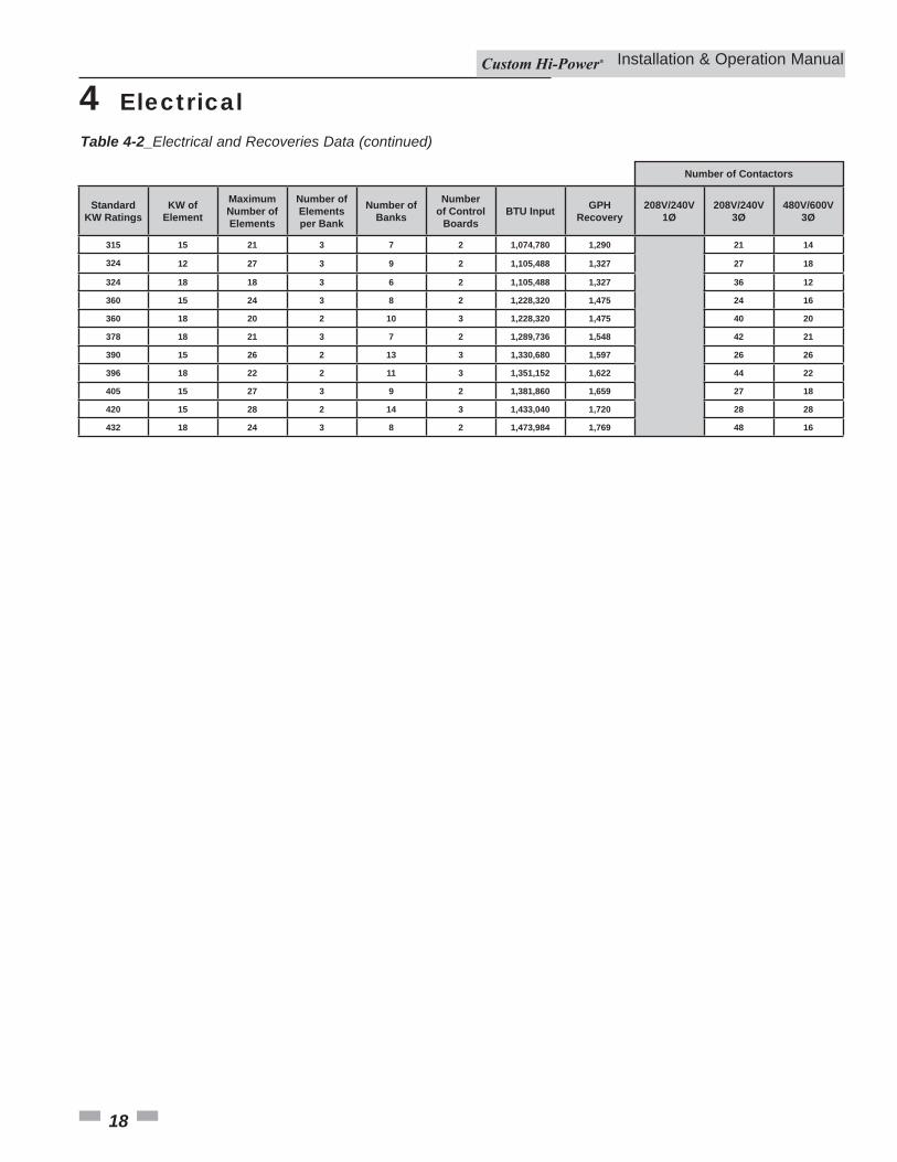
Table 4-2_Electrical and Recoveries Data (continued)
StandardKW Ratings
KW of Element
Maximum Number of Elements
Number of Elements per Bank
Number of Banks
Number of Control
BoardsBTU Input GPH
Recovery208V/240V
1Ø208V/240V
3Ø480V/600V
3Ø
315 15 21 3 7 2 1,074,780 1,290 21 14
324 12 27 3 9 2 1,105,488 1,327 27 18
324 18 18 3 6 2 1,105,488 1,327 36 12
360 15 24 3 8 2 1,228,320 1,475 24 16
360 18 20 2 10 3 1,228,320 1,475 40 20
378 18 21 3 7 2 1,289,736 1,548 42 21
390 15 26 2 13 3 1,330,680 1,597 26 26
396 18 22 2 11 3 1,351,152 1,622 44 22
405 15 27 3 9 2 1,381,860 1,659 27 18
420 15 28 2 14 3 1,433,040 1,720 28 28
432 18 24 3 8 2 1,473,984 1,769 48 16
Number of Contactors
4 Electrical
Installation & Operation Manual
18
19
GeneralRefer to the Features and Components section of this manual for the location of components mentioned in the instructions that follow.NEVER operate the heating elements without being certain the water heater is fi lled with water and a temperature and pressure relief valve is installed in the relief valve opening on top of the heater.A low water cutoff is provided on all heaters as standard equipment. Th e water probe is installed near the top of the tank to monitor the presence of water. Th e control circuit is opened if the water level is below this point.Th e pilot switch (power on/off toggle switch) on the cabinet front permits the heater to be turned on and off without having to operate the electrical disconnect switch.
5 Operation
Full power is present whenever the cabinet door is opened, even with the pilot switch turned off.
� DANGER
Optional manual override switches on the cabinet front allow elements to be manually de-energized if full capacity is not needed.
Filling the Water Heater
CAUTION In order to avoid heating element damage, fill the tank with water before operating.
To fi ll the water heater with water:1. Turn OFF the electrical disconnect switch.2. Turn OFF the ON/OFF switch.3. Close the heater drain valve.4. Open a nearby hot water faucet to allow the air in the system
to escape.5. Fully open the cold water inlet valve, fi lling the heater and
piping.6. Close the hot water faucet when the water starts to fl ow from
the faucet. Leave the cold water inlet valve fully open. Th e heater is now ready for start-up and temperature regulation.
7. Close the cabinet door and perform the start-up checks listed below before turning on the electricity.
Initial Start-upTh e following checks should be made by the installer when the water heater is placed into operation for the fi rst time:1. Check all factory and fi eld-made water and electrical
connections for tightness. Also check connections on top of the heater. Repair water leaks and tighten electrical connections as necessary.
2. Turn on the electrical disconnect switch and pilot toggle switch. Th e pilot toggle switch is located on the cabinet.
3. Observe the operation of the electrical components during the fi rst heating cycle. Exercise care as the electrical circuits are energized.
Temperature control and contactor operation should be checked by allowing the heater to come up to temperature and shut off automatically. Exercise care as the electrical circuits are energized.
Draining the Water HeaterTh e water heater must be drained if it is to be shut down and/or exposed to freezing temperatures. Maintenance and service procedures may also require draining the heater.1. Turn OFF the electrical disconnect switch.2. Turn OFF the ON/OFF switch.3. Close the cold water inlet valve to heater.4. Open a nearby hot water faucet to vent the system.5. Open the drain valve.6. If the the heater is being drained for an extended shutdown,
it is suggested that the drain valve be left open during this period.
Follow Filling the water heater instructions when restoring hot water service. See the list above.
Burn hazard. Keep clear of drain valve discharge outlet.� DANGER
Installation & Operation Manual
20
If a dry bulb style high limit is used in place of a surface mount in the limit, it should not be set above 190°F/88°C.When the high limit switch contacts open, the electronic control system locks out and displays a fault message. Voltage to the contactor coils and heating elements is terminated to prevent further heating operation. Once the water temperature has cooled below this point, press the manual reset button. Th en the power supply to the water heater must be turned off and then back on to reset the control system.
High Temperature Limit Controls (ECO)
Water temperature over 125°F (52°C) can cause severe burns instantly resulting in severe injury or death. Children, the elderly, and the physically or mentally disabled are at highest risk for scald injury. Feel water before bathing or showering. Temperature limiting devices such as mixing valves must be installed when required by codes and to ensure safe temperatures at fixtures. Read the instruction manual for safe temperature setting.
� DANGER
Th e water heaters covered in this instruction manual are equipped with adjustable thermostat controls to control water temperature. Hot water temperatures required for automatic dishwasher and laundry use can cause scald burns resulting in serious personal injury and/or death. Th e temperature at which injury occurs varies with the person’s age and duration of exposure. Th e slower response time of children, the elderly, or disabled persons increases the hazards to them. Never allow small children to use a hot water tap or draw their own bath water. Never leave a child or disabled person unattended in a bathtub or shower. Th e water heater should be located in an area where the general public does not have access to set temperatures.Setting the water heater temperatures at 120°F will reduce the risk of scalds. Some states require settings at specifi c lower temperatures.
Water Temperature °F Time for 1st Degree Burn(Less Severe Burns)
Time for Permanent Burns2nd & 3rd Degree
(Most Severe Burns)110 (normal shower temp.)116 (pain threshold)116 35 minutes 45 minutes122 1 minute 5 minutes131 5 seconds 25 seconds140 2 seconds 5 seconds149 1 second 2 seconds154 Instantaneous 1 second
(U.S. Government Memorandum, C.P.S.C., Peter L. Armstrong, Sept. 15, 1978)
Full power is present whenever the cabinet door is opened, even with the ON/OFF switch turned off.
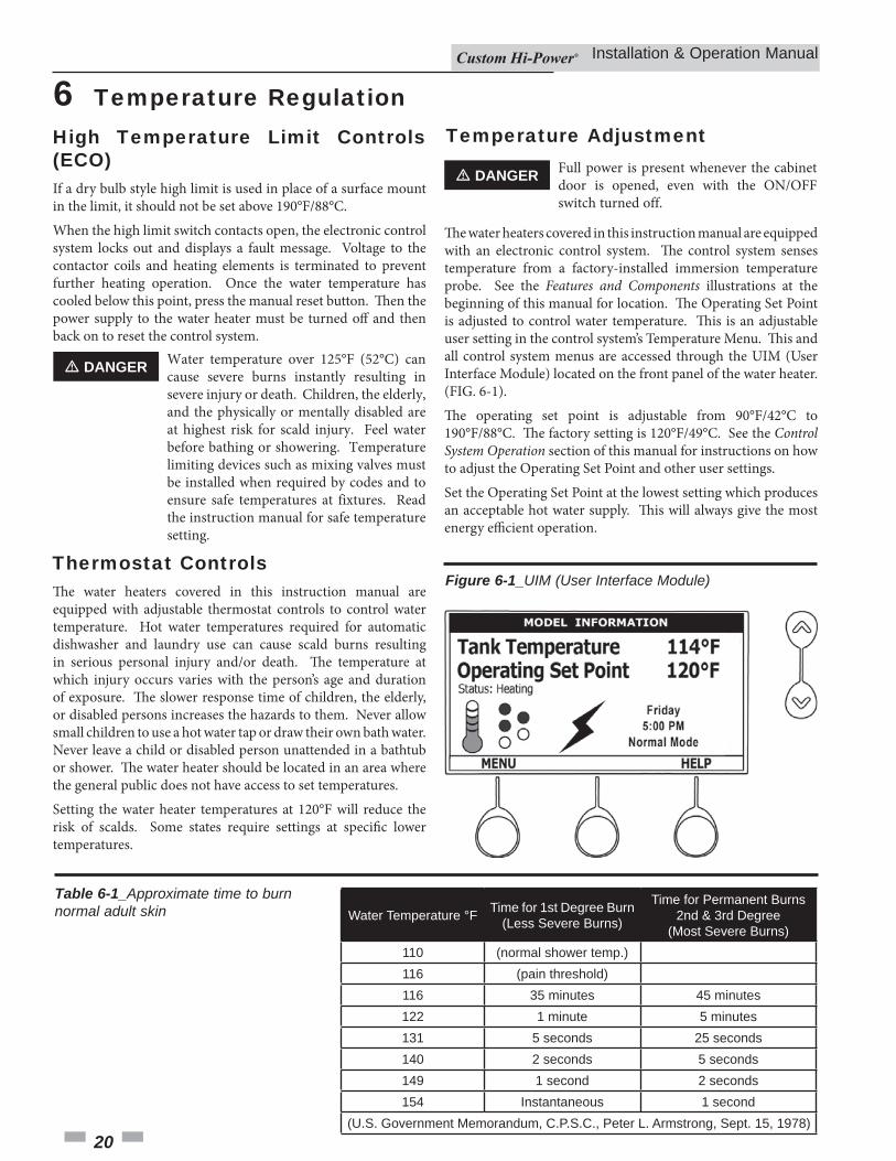
� DANGER
Th e water heaters covered in this instruction manual are equipped with an electronic control system. Th e control system senses temperature from a factory-installed immersion temperature probe. See the Features and Components illustrations at the beginning of this manual for location. Th e Operating Set Point is adjusted to control water temperature. Th is is an adjustable user setting in the control system’s Temperature Menu. Th is and all control system menus are accessed through the UIM (User Interface Module) located on the front panel of the water heater. (FIG. 6-1).Th e operating set point is adjustable from 90°F/42°C to 190°F/88°C. Th e factory setting is 120°F/49°C. See the Control System Operation section of this manual for instructions on how to adjust the Operating Set Point and other user settings.Set the Operating Set Point at the lowest setting which produces an acceptable hot water supply. Th is will always give the most energy effi cient operation.
Figure 6-1_UIM (User Interface Module)
6 Temperature Regulation
Thermostat Controls
Table 6-1_Approximate time to burn normal adult skin
Temperature Adjustment
Installation & Operation Manual
21
Progressive Sequencing: Banks are energized and de-energized according to adjustable (1 to 20°F) diff erential set points for each bank. Th e fi rst bank on is rotated with each successive call for heat (bank rotation). Th e fi rst heating bank energized at the beginning of a heating cycle is the fi rst bank de-energized at the end of the heating cycle (First on/fi rst off ). Successive heating cycles would progress as follows on a model equipped with three (3) heating bank:• First heating cycle: Banks come on [1, 2, 3] and cycle off
[1, 2, 3]• Second heating cycle: Banks come on [2, 3, 1] and cycle off
[2, 3, 1]• Th ird heating cycle: Banks come on [3, 1, 2] and cycle off
[3, 1, 2]• Fourth heating cycle: Pattern repeats - same as fi rst heating
cycle
Heating Banks Operation
7 Control System Operation
Advanced DiagnosticsPlain English text and animated icons display detailed operational and diagnostic information. Th e LCD screen on the front of the water heater displays the sequence of operation in real time. Fault or alert messages are displayed when operational problems occur. Th e Advanced Service Menu displays a list of possible causes for current fault and alert conditions to aid in servicing.Economy Mode OperationTh e control system automatically lowers the Operating Set Point by a programmed value during user defi ned time periods. Th is helps reduce operating costs during unoccupied or peak demand periods.
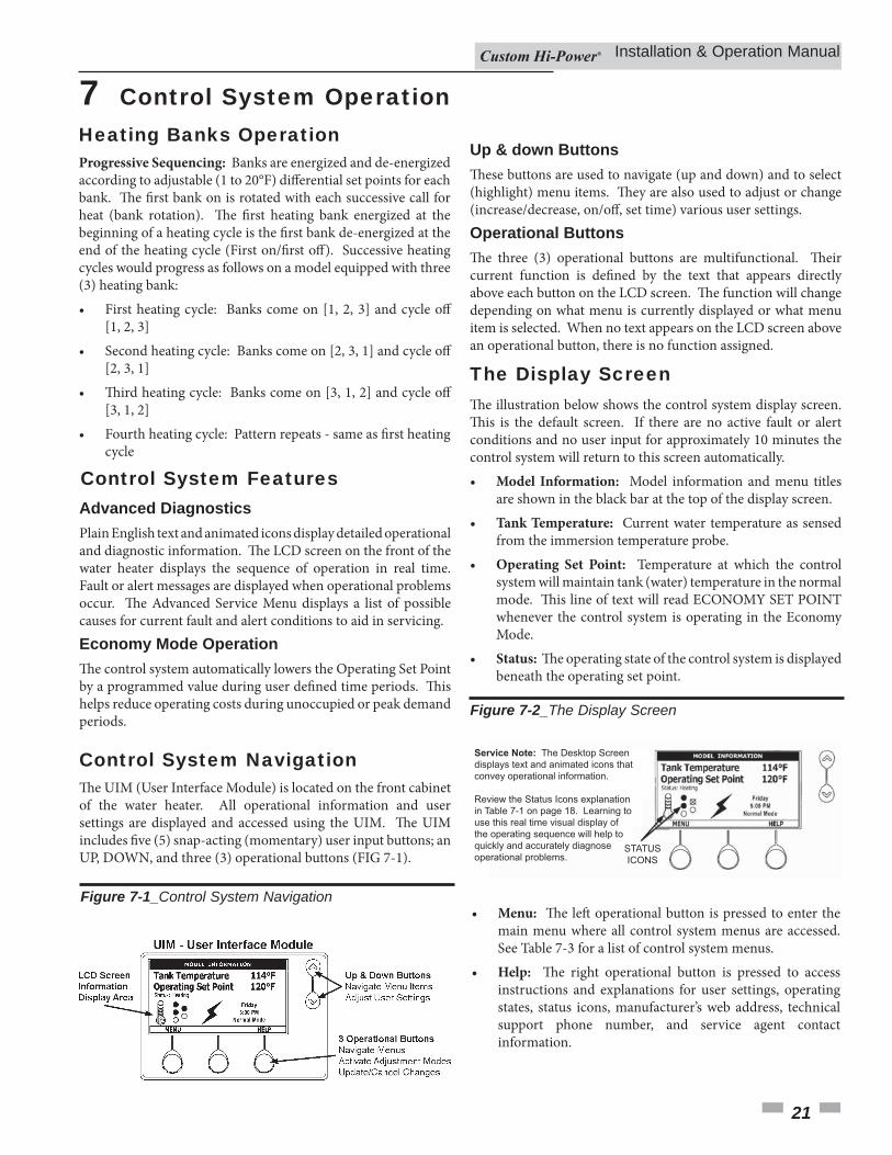
Th e UIM (User Interface Module) is located on the front cabinet of the water heater. All operational information and user settings are displayed and accessed using the UIM. Th e UIM includes fi ve (5) snap-acting (momentary) user input buttons; an UP, DOWN, and three (3) operational buttons (FIG 7-1).
Figure 7-1_Control System Navigation
Up & down ButtonsTh ese buttons are used to navigate (up and down) and to select (highlight) menu items. Th ey are also used to adjust or change (increase/decrease, on/off , set time) various user settings.Operational ButtonsTh e three (3) operational buttons are multifunctional. Th eir current function is defi ned by the text that appears directly above each button on the LCD screen. Th e function will change depending on what menu is currently displayed or what menu item is selected. When no text appears on the LCD screen above an operational button, there is no function assigned.
Th e illustration below shows the control system display screen. Th is is the default screen. If there are no active fault or alert conditions and no user input for approximately 10 minutes the control system will return to this screen automatically.• Model Information: Model information and menu titles
are shown in the black bar at the top of the display screen.• Tank Temperature: Current water temperature as sensed
from the immersion temperature probe.• Operating Set Point: Temperature at which the control
system will maintain tank (water) temperature in the normal mode. Th is line of text will read ECONOMY SET POINT whenever the control system is operating in the Economy Mode.
• Status: Th e operating state of the control system is displayed beneath the operating set point.
Figure 7-2_The Display Screen
Service Note: The Desktop Screen displays text and animated icons that convey operational information.
Review the Status Icons explanation in Table 7-1 on page 18. Learning to use this real time visual display of the operating sequence will help to quickly and accurately diagnose operational problems.
STATUSICONS
• Menu: Th e left operational button is pressed to enter the main menu where all control system menus are accessed. See Table 7-3 for a list of control system menus.
• Help: Th e right operational button is pressed to access instructions and explanations for user settings, operating states, status icons, manufacturer’s web address, technical support phone number, and service agent contact information.
Control System Features
Control System Navigation
The Display Screen
Installation & Operation Manual
22
7 Control System Operation
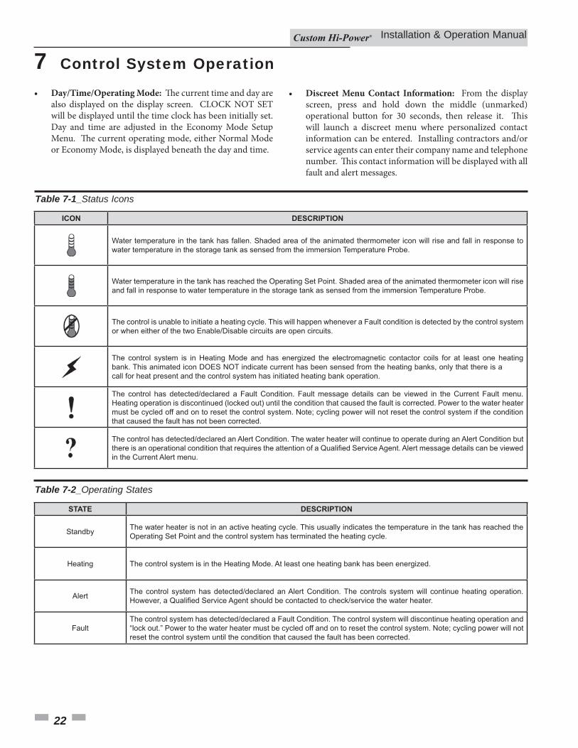
Table 7-1_Status Icons
ICON DESCRIPTION
Water temperature in the tank has fallen. Shaded area of the animated thermometer icon will rise and fall in response to water temperature in the storage tank as sensed from the immersion Temperature Probe.
Water temperature in the tank has reached the Operating Set Point. Shaded area of the animated thermometer icon will rise and fall in response to water temperature in the storage tank as sensed from the immersion Temperature Probe.
The control is unable to initiate a heating cycle. This will happen whenever a Fault condition is detected by the control system or when either of the two Enable/Disable circuits are open circuits.
The control system is in Heating Mode and has energized the electromagnetic contactor coils for at least one heating bank. This animated icon DOES NOT indicate current has been sensed from the heating banks, only that there is a call for heat present and the control system has initiated heating bank operation.
The control has detected/declared a Fault Condition. Fault message details can be viewed in the Current Fault menu. Heating operation is discontinued (locked out) until the condition that caused the fault is corrected. Power to the water heater must be cycled off and on to reset the control system. Note; cycling power will not reset the control system if the condition that caused the fault has not been corrected.
The control has detected/declared an Alert Condition. The water heater will continue to operate during an Alert Condition but
in the Current Alert menu.
Table 7-2_Operating States
DESCRIPTIONSTATE
Standby
Heating The control system is in the Heating Mode. At least one heating bank has been energized.
Alert
The water heater is not in an active heating cycle. This usually indicates the temperature in the tank has reached the Operating Set Point and the control system has terminated the heating cycle.
Fault
The control system has detected/declared an Alert Condition. The controls system will continue heating operation.
The control system has detected/declared a Fault Condition. The control system will discontinue heating operation and “lock out.” Power to the water heater must be cycled off and on to reset the control system. Note; cycling power will not reset the control system until the condition that caused the fault has been corrected.
• Day/Time/Operating Mode: Th e current time and day are also displayed on the display screen. CLOCK NOT SET will be displayed until the time clock has been initially set. Day and time are adjusted in the Economy Mode Setup Menu. Th e current operating mode, either Normal Mode or Economy Mode, is displayed beneath the day and time.
• Discreet Menu Contact Information: From the display screen, press and hold down the middle (unmarked) operational button for 30 seconds, then release it. Th is will launch a discreet menu where personalized contact information can be entered. Installing contractors and/or service agents can enter their company name and telephone number. Th is contact information will be displayed with all fault and alert messages.
Installation & Operation Manual
23
7 Control System Operation (continued)
Table 7-3_Control System Menus
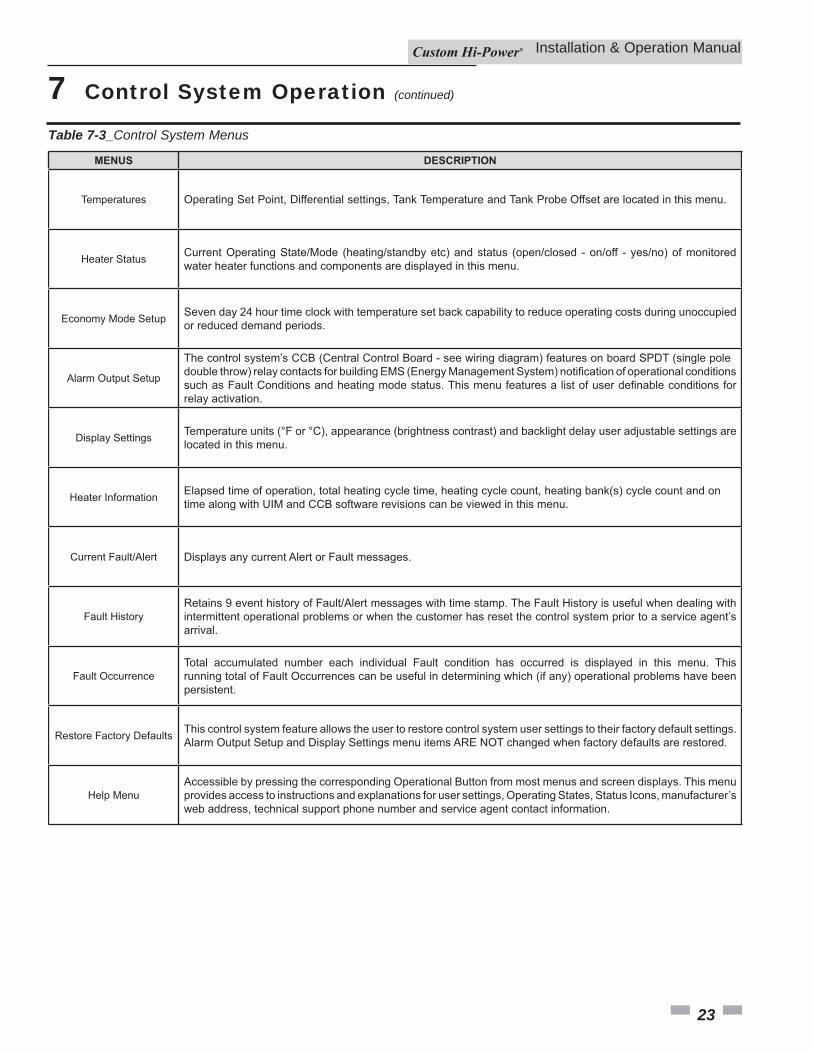
MENUS DESCRIPTION
Temperatures
Heater Status
Economy Mode Setup
Operating Set Point, Differential settings, Tank Temperature and Tank Probe Offset are located in this menu.
Current Operating State/Mode (heating/standby etc) and status (open/closed - on/off - yes/no) of monitored water heater functions and components are displayed in this menu.
Alarm Output Setup
Seven day 24 hour time clock with temperature set back capability to reduce operating costs during unoccupied or reduced demand periods.
Display Settings
Heater Information
Temperature units (°F or °C), appearance (brightness contrast) and backlight delay user adjustable settings are located in this menu.
Current Fault/Alert
Fault History
Displays any current Alert or Fault messages.
The control system’s CCB (Central Control Board - see wiring diagram) features on board SPDT (single pole
relay activation.
Elapsed time of operation, total heating cycle time, heating cycle count, heating bank(s) cycle count and on time along with UIM and CCB software revisions can be viewed in this menu.
Fault Occurrence
Restore Factory Defaults
Retains 9 event history of Fault/Alert messages with time stamp. The Fault History is useful when dealing with intermittent operational problems or when the customer has reset the control system prior to a service agent’s arrival.
Help Menu
Total accumulated number each individual Fault condition has occurred is displayed in this menu. This running total of Fault Occurrences can be useful in determining which (if any) operational problems have been persistent.
This control system feature allows the user to restore control system user settings to their factory default settings. Alarm Output Setup and Display Settings menu items ARE NOT changed when factory defaults are restored.
Accessible by pressing the corresponding Operational Button from most menus and screen displays. This menu provides access to instructions and explanations for user settings, Operating States, Status Icons, manufacturer’s web address, technical support phone number and service agent contact information.
Installation & Operation Manual
24
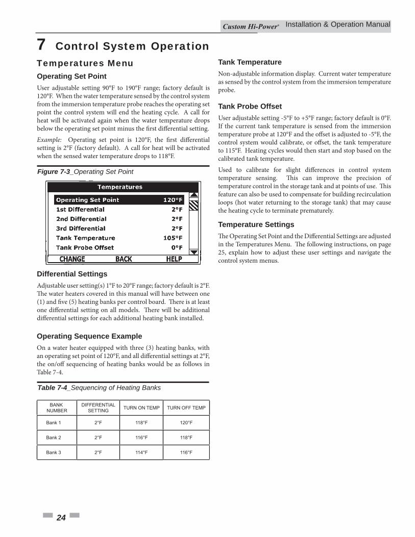
Operating Set PointUser adjustable setting 90°F to 190°F range; factory default is 120°F. When the water temperature sensed by the control system from the immersion temperature probe reaches the operating set point the control system will end the heating cycle. A call for heat will be activated again when the water temperature drops below the operating set point minus the fi rst diff erential setting.Example: Operating set point is 120°F, the fi rst diff erential setting is 2°F (factory default). A call for heat will be activated when the sensed water temperature drops to 118°F.
Differential SettingsAdjustable user setting(s) 1°F to 20°F range; factory default is 2°F. Th e water heaters covered in this manual will have between one (1) and fi ve (5) heating banks per control board. Th ere is at least one diff erential setting on all models. Th ere will be additional diff erential settings for each additional heating bank installed.
Operating Sequence ExampleOn a water heater equipped with three (3) heating banks, with an operating set point of 120°F, and all diff erential settings at 2°F, the on/off sequencing of heating banks would be as follows in Table 7-4.
Tank TemperatureNon-adjustable information display. Current water temperature as sensed by the control system from the immersion temperature probe.
Tank Probe OffsetUser adjustable setting -5°F to +5°F range; factory default is 0°F. If the current tank temperature is sensed from the immersion temperature probe at 120°F and the off set is adjusted to -5°F, the control system would calibrate, or off set, the tank temperature to 115°F. Heating cycles would then start and stop based on the calibrated tank temperature.Used to calibrate for slight diff erences in control system temperature sensing. Th is can improve the precision of temperature control in the storage tank and at points of use. Th is feature can also be used to compensate for building recirculation loops (hot water returning to the storage tank) that may cause the heating cycle to terminate prematurely.
BANKNUMBER
DIFFERENTIAL SETTING TURN ON TEMP TURN OFF TEMP
Bank 1 2°F 118°F 120°F
Bank 2 2°F 116°F 118°F
Bank 3 2°F 114°F 116°F
7 Control System Operation
Temperature SettingsTh e Operating Set Point and the Diff erential Settings are adjusted in the Temperatures Menu. Th e following instructions, on page 25, explain how to adjust these user settings and navigate the control system menus.
Temperatures Menu
Figure 7-3_Operating Set Point
Table 7-4_Sequencing of Heating Banks
Installation & Operation Manual
25
ACTION DISPLAY
From the Desktop Screen, press the Operational Button underneath “MENU” to enter the Main Menu.
Notice how the text above the Operational Buttons on the display changes as you navigate through the various menus and screens.
With the Operating Set Point selected (highlighted in black) in the Temperatures Menu, press the Operational Button underneath “CHANGE” to activate the adjustment mode for this menu item.
With Temperatures selected (highlight in black) in the Main Menu, press the Operational Button underneath “SELECT” to enter the Temperature Menu.
If Temperatures is not selected use the Up and Down buttons to select this menu item.
Press the Up and Down buttons to adjust the Operating Set Point to the desired setting.
setting. Press the Operational Button underneath “CANCEL” to discard the new setting and retain the previous setting.
The new Operating Set Point value should now be displayed as the current value.
NOTE: Use this same procedure to adjust the Differential settings and the Tank Probe Offset in the Temperatures Menu.
This same procedure is used to change user settings in other control system menus.
7 Control System Operation (continued)
Table 7-5_Temperature Screens
Installation & Operation Manual
26
7 Control System Operation
Th is menu displays non-adjustable operational information. Use the up and down buttons to navigate to the bottom of this menu.
Figure 7-4_Status Menu Screens
Bank 1 On
Bank 2 On
Banks OnStatus
ECO Contact
Enable / Disable 1
Enable / Disable 2
Heating
1Closed
Closed
Closed
Yes
No
Alarm Condition
Alarm Relay Output
Bank 1 OnEnable / Disable 2
Bank 2 On
Bank 3 On
Tank Full
Closed
YesNo
No
Yes
No
Open
TOP OF MENU
BOTTOM OF MENU
StatusDisplays the current operating state of the control system, such as heating, standby, and fault.
Banks On #Displays the number of heating elements the control system has energized.
ECO ContactDisplays the current state of the ECO high temperature limit switch contacts.
Enable / Disable 1 & 2Displays the current state, open or closed, of the two enable/disable circuits (J7 socket on the CCB - see wiring diagrams) provided for external supervisory controls such as building EMS (Energy Management System). Both of these enable/disable circuits must be closed to enable heating operation. If either enable/disable circuit is open for any reason, heating operation will be disabled. Th ere is a plug with two jumper wires installed from the factory in the CCB J7 socket to enable heating operation when external controls are not in use.NOTE: If a supervisory control is used to enable or disable heating operation, install fi eld wiring between the J7 socket on the CCB and a set of dry contacts on the external control per all applicable building codes. Th is is a switching circuit only. DO NOT apply any external voltage or connect any load (i.e., relay coil) to either circuit.
Element # OnDisplays the on/off status of each heating bank. Yes = On, No = Off .
Tank FullDisplays the status of the LWCO (Low Water Cut Off ) device. Yes = water level is acceptable, No = water level is low.
Alarm ConditionDisplays the status of the user defi nable alarm output function - see alarm output setup menu. Yes = alarm condition has been met, No = alarm condition has not been met.
Alarm Relay OutputDisplays the state of the normally open contacts of the alarm output relay. Th is relay (J3 contacts on the CCB - see wiring diagrams) is used for building EMS (Energy Management System) notifi cation of operational conditions such as fault conditions.
Water Heater Status Menu
Installation & Operation Manual
27
Th is menu contains settings used to establish an economy set point and economy mode operating periods, or night setback. Th is control system feature can help reduce operating costs during unoccupied, low load, or peak demand periods.
7 Control System Operation (continued)
Figure 7-5_Economy Mode Screens
DISPLAY SCREEN DURING ECONOMY MODE
ECONOMY MODE SETUP MENU
Set Point AdjustmentAdjustable user setting (2°F to 50°F - factory default is 20°F) the control system uses to calculate the Economy Set Point. Th e Economy Set Point is the normal operating set point minus the programmed set point adjustment value.Th e Economy Set Point is the water temperature that the control system maintains during programmed economy mode time periods. ECONOMY SET POINT is displayed instead of OPERATING SET POINT, and ECONOMY MODE appears beneath the current time on the display screen during economy mode time periods.
Current TimeSeven Day 24 hr clock. Use this menu item to set the current time and day of the week. Current day and time are not set from the factory. CLOCK NOT SET will be displayed on the display until the time/day has been initially set. NOTE: Th e time will not self adjust for Daylight Savings Time.
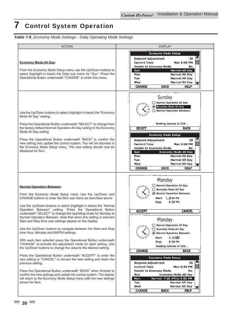
Daily Operating Mode (Sun - Mon - Tue - Wed - Thu - Fri - Sat)Seven daily sub menus are listed at the bottom of the Economy Mode Setup menu. Th ere are 3 Operating Modes in each sub menu. Normal Operation All Day, Economy Mode All Day, and Normal Operation Between. Only one Operating Mode can be active. Th e factory default is Normal Operation All Day.
Normal Operation All Day: When this operating mode is active, the normal Operating Set Point is used for the entire day.Economy Mode All Day: When this operating mode is active the Economy Set Point is used for the entire day.Normal Operation Between: When this operating mode is active, there will also be start and stop times to program. Th e normal Operating Set Point is used between the programmed start and stop times, and the Economy Set Point will be in eff ect during the rest of the day. Th ere is one start time and one stop time event per day.
Economy Mode Setup Menu
Installation & Operation Manual
28
7 Control System OperationTable 7-6_Economy Mode Settings - Setpoint Adjustment Value
ACTION DISPLAY
From the Display Screen, press the Operational Button underneath “MENU” to enter the Main Menu.
Notice how the text above the Operational Buttons on the display changes as you navigate through the various menus and screens.
Use the Up/Down buttons to select (highlight in black) the Economy Mode Setup menu from the Main Menu. Press the Operational Button underneath “SELECT” to enter the Economy Mode Setup menu.
Use the Up/Down buttons to select (highlight in black) Setpoint Adjustment. Press the Operational Button underneath “CHANGE” to activate the adjustment mode for the Setpoint Adjustment value.
The new Setpoint Adjustment value should now be displayed as the current value.
Use the Up/Down buttons to change the Setpoint Adjustment to the desired value. The Setpoint Adjustment value is adjustable from 2°F to 50°F. The factory default is 20°F.
Notice how the text above the Operational Buttons on the display changes to “UPDATE” & “CANCEL” when the adjustment mode is activated and how the current value is outlined rather than highlighted in black.
the new value. Pressing the Operational Button underneath “CANCEL” would discard the new value and retain the previous value.
Installation & Operation Manual
29
7 Control System Operation (continued)
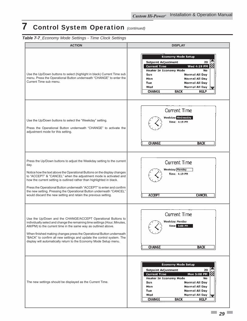
Table 7-7_Economy Mode Settings - Time Clock Settings
ACTION DISPLAY
Use the Up/Down buttons to select the “Weekday” setting.
Press the Operational Button underneath “CHANGE” to activate the adjustment mode for this setting.
Use the Up/Down buttons to select (highlight in black) Current Time sub menu. Press the Operational Button underneath “CHANGE” to enter the Current Time sub menu.
The new settings should be displayed as the Current Time.
Press the Up/Down buttons to adjust the Weekday setting to the current day.
Notice how the text above the Operational Buttons on the display changes to “ACCEPT” & “CANCEL” when the adjustment mode is activated and how the current setting is outlined rather than highlighted in black.
the new setting. Pressing the Operational Button underneath “CANCEL” would discard the new setting and retain the previous setting.
Use the Up/Down and the CHANGE/ACCEPT Operational Buttons to individually select and change the remaining time settings (Hour, Minutes, AM/PM) to the current time in the same way as outlined above.
display will automatically return to the Economy Mode Setup menu.
Installation & Operation Manual
30
7 Control System OperationTable 7-8_Economy Mode Settings - Daily Operating Mode Settings
ACTION DISPLAY
Economy Mode All Day:
From the Economy Mode Setup menu use the Up/Down buttons to select (highlight in black) the Daily sub menu for “Sun.” Press the Operational Button underneath “CHANGE” to enter this menu.
Use the Up/Down buttons to select (highlight in black) the “Economy Mode All Day” setting.
Press the Operational Button underneath “SELECT” to change from the factory default Normal Operation All Day setting to the Economy Mode All Day setting.
new setting and update the control system. You will be returned to the Economy Mode Setup menu. The new setting should now be displayed for Sun.
Normal Operation Between:
From the Economy Mode Setup menu Use the Up/Down and CHANGE buttons to enter the Mon sub menu as described above.
Use the Up/Down buttons to select (highlight in black) the “Normal Operation Between” setting. Press the Operational Button underneath “SELECT” to change the operating mode for Monday to Normal Operation Between. Note that when this setting is selected Start and Stop time user settings appear on the display.
Use the Up/Down buttons to navigate between the Start and Stop time Hour, Minutes and AM/PM settings.
With each item selected press the Operational Button underneath “CHANGE” to activate the adjustment mode for each setting. Use the Up/Down buttons to change the value to the desired setting.
Press the Operational Button underneath “ACCEPT” to enter the new setting or “CANCEL” to discard the new setting and retain the previous setting.
will return to the Economy Mode Setup menu with the new settings shown for Mon.
Installation & Operation Manual
31
7 Control System Operation (continued)
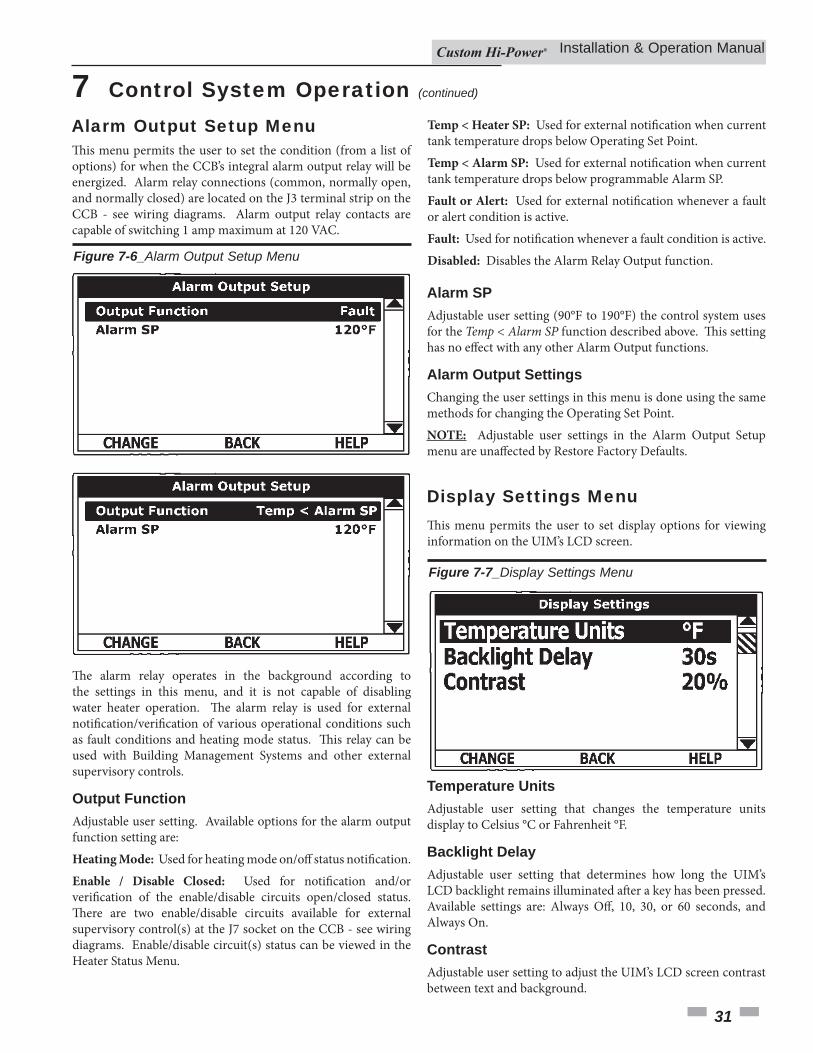
Th is menu permits the user to set the condition (from a list of options) for when the CCB’s integral alarm output relay will be energized. Alarm relay connections (common, normally open, and normally closed) are located on the J3 terminal strip on the CCB - see wiring diagrams. Alarm output relay contacts are capable of switching 1 amp maximum at 120 VAC.
Th e alarm relay operates in the background according to the settings in this menu, and it is not capable of disabling water heater operation. Th e alarm relay is used for external notifi cation/verifi cation of various operational conditions such as fault conditions and heating mode status. Th is relay can be used with Building Management Systems and other external supervisory controls.
Output FunctionAdjustable user setting. Available options for the alarm output function setting are:Heating Mode: Used for heating mode on/off status notifi cation.Enable / Disable Closed: Used for notifi cation and/or verifi cation of the enable/disable circuits open/closed status. Th ere are two enable/disable circuits available for external supervisory control(s) at the J7 socket on the CCB - see wiring diagrams. Enable/disable circuit(s) status can be viewed in the Heater Status Menu.
Temp < Heater SP: Used for external notifi cation when current tank temperature drops below Operating Set Point.Temp < Alarm SP: Used for external notifi cation when current tank temperature drops below programmable Alarm SP.Fault or Alert: Used for external notifi cation whenever a fault or alert condition is active.Fault: Used for notifi cation whenever a fault condition is active.Disabled: Disables the Alarm Relay Output function.
Alarm SPAdjustable user setting (90°F to 190°F) the control system uses for the Temp < Alarm SP function described above. Th is setting has no eff ect with any other Alarm Output functions.
Alarm Output SettingsChanging the user settings in this menu is done using the same methods for changing the Operating Set Point.NOTE: Adjustable user settings in the Alarm Output Setup menu are unaff ected by Restore Factory Defaults.
Figure 7-6_Alarm Output Setup Menu
Th is menu permits the user to set display options for viewing information on the UIM’s LCD screen.
Figure 7-7_Display Settings Menu
Temperature UnitsAdjustable user setting that changes the temperature units display to Celsius °C or Fahrenheit °F.
Backlight DelayAdjustable user setting that determines how long the UIM’s LCD backlight remains illuminated aft er a key has been pressed. Available settings are: Always Off , 10, 30, or 60 seconds, and Always On.
ContrastAdjustable user setting to adjust the UIM’s LCD screen contrast between text and background.
Alarm Output Setup Menu
Display Settings Menu
Installation & Operation Manual
32
Display SettingsChanging the user settings in this menu is done using the same methods for changing the Operating Set Point. NOTE: Adjustable user settings in the Display Settings menu are unaff ected by Restore Factory Defaults.
7 Control System Operation
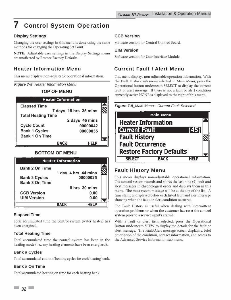
Th is menu displays non-adjustable operational information.
Figure 7-8_Heater Information Menu
Bank 1 On Time
00000035Bank 1 Cycles
00000042
2 days 46 mins
Total Heating Time
Elapsed Time
Cycle Count
7 days 18 hrs 35 mins
UIM Version 0.00
CCB Version 0.00
8 hrs 30 mins
Bank 3 Cycles
Bank 2 On Time
Bank 3 On Time
1 day 4 hrs 44 mins00000025
TOP OF MENU
BOTTOM OF MENU
Elapsed TimeTotal accumulated time the control system (water heater) has been energized.
Total Heating TimeTotal accumulated time the control system has been in the heating mode (i.e., any heating elements have been energized).
Bank # CyclesTotal accumulated count of heating cycles for each heating bank.
Bank # On TimeTotal accumulated heating on time for each heating bank.
CCB VersionSoft ware version for Central Control Board.
UIM VersionSoft ware version for User Interface Module.
Th is menu displays non-adjustable operation information. With the Fault History sub menu selected in Main Menu, press the Operational button underneath SELECT to display the current fault or alert message. If there is not a fault or alert condition currently active NONE is displayed to the right of this menu.
Figure 7-9_Main Menu - Current Fault Selected
Th is menu displays non-adjustable operational information. Th e control system records and stores the last nine (9) fault and alert messages in chronological order and displays them in this menu. Th e most recent message will be at the top of the list. A time stamp is displayed below each listed fault and alert message showing when the fault or alert condition occurred.Th e Fault History is useful when dealing with intermittent operation problems or when the customer has reset the control system prior to a service agent’s arrival.With a fault or alert item selected, press the Operational Button underneath VIEW to display the details for the fault or alert message. Th e Fault/Alert message screen displays a brief description of the condition, contact information, and access to the Advanced Service Information sub menu.
Heater Information Menu Current Fault / Alert Menu
Fault History Menu
Installation & Operation Manual
33
Figure 7-10_Fault History Screens
7 Control System Operation (continued)
FAULT HISTORY MENU
CURRENT / HISTORY FAULT MESSAGE
Th is menu displays the total accumulated number of times each individual fault condition has occurred. Th is running total of fault occurrences can be useful in determining which, if any, operational problems have been persistent.
Figure 7-11_Fault Occurrence Menu
Fault Occurrence Menu
Installation & Operation Manual
34
7 Control System Operation
Th is control system menu allows the user to restore most of the control system’s user settings to their factory default settings. User settings in the Alarm Output Setup and Display Settings menus are unaff ected by executing Restore Factory Defaults.
Table 7-9_Restore Factory Defaults
ACTION DISPLAY
From the Main Menu use the Up/Down buttons to select (highlight in black) the “Restore Factory Defaults” menu.
Press the Operational Button underneath “SELECT.” The Restore Factory Defaults menu will be displayed.
From the Restore Factory Defaults menu press the Operational Button
default settings have been restored.
Press the Operational Button underneath “BACK” to exit the Restore Factory Defaults menu.
Restore Factory Defaults Menu
Installation & Operation Manual
35
8 Maintenance
Burn hazard. Keep clear of drain valve discharge outlet.� DANGER
Periodically, the drain valve should be opened and the water allowed to run until it fl ows clean. Th is will help to prevent sediment buildup in the tank bottom.Periodically check the temperature and pressure relief valve to ensure that it is in operating condition. Lift the lever at the top of the valve several times until the valve seats properly and operates freely.Water heater maintenance includes periodic tank fl ushing and cleaning and removal of lime scale from the heating element.Th e heater tank is equipped with an anode rod to aid in corrosion control and should be inspected periodically (see Anode Rod Inspection).
Each water heater contains at least one (1) anode rod, which will slowly deplete, due to electrolysis, prolonging the life of the water heater by protecting the glass-lined tank from corrosion. Adverse water quality, hotter water temperatures, high hot water usage, hydronic heating devices, and water soft ening methods can increase the rate of anode rod depletion. Once the anode rod is depleted, the tank will start to corrode, eventually developing a leak.Artifi cially soft ened water is exceedingly corrosive because the process substitutes sodium ions for magnesium and calcium ions.Th e use of a water soft ener may decrease the life of the water heater tank.Th e anode rod should be inspected aft er a maximum of three (3) years and annually thereaft er until the condition of the anode rod dictates its replacement.NOTE: Artifi cially soft ened water requires the anode rod to be inspected annually.
All water heaters eventually leak. Do not install without adequate drainage. CAUTION
Th e following are typical, but not all, signs of a depleted anode rod:• Th e majority of the rods diameter is less than 3/8".• Signifi cant sections of the support wire (approximately 1/3
or more of the anode rod’s length) are visible.If the anode rod shows signs of either or both, it should be replaced. NOTE: Whether re-installing or replacing the anode rod, check for any leaks and immediately correct if found.To replace the anode:1. Turn OFF electric supply to the water heater.2. Shut OFF the water supply and open a nearby hot water
faucet to depressurize the water tank.3. Drain the tank. Refer to Draining and Flushing for proper
procedures. Close the drain valve.4. Remove the old anode rod.5. Use Tefl on® tape or approved pipe sealant on threads, and
install a new anode rod.6. Turn ON water supply and open a nearby hot water faucet
to purge air from the water system. Check for any leaks and immediately correct any if found.
7. Restart the water heater as directed in this manual. See the Features and Components illustrations for anode rod location.
1. Turn OFF the electrical supply to the water heater at the breaker or disconnect switch.
2. Ensure the cold water inlet valve is open.3. Open a nearby hot water faucet and let the water run until
the water is no longer hot, then close the hot water faucet.4. Connect a hose to the water heater drain valve and terminate
it to an adequate drain.5. Ensure that the drain hose is secured before and during
the entire fl ushing procedure. Flushing is performed with system water pressure applied to the water heater.
6. Open the water heater drain valve to fl ush the storage tank.7. Flush the water heater storage tank to remove sediment and
allow the water to fl ow until it runs clean.8. Close the water heater drain valve when fl ushing is
completed.9. Remove the drain hose.10. Fill the water heater (see the Filling the Water Heater section
in this manual).11. Turn ON the electrical supply to the water heater.12. Place the water heater back in operation. Allow the water
heater to complete several heating cycles to ensure it is operating properly.
General
Anode Rod Inspection
Flushing the Water Heater
Installation & Operation Manual
8 Maintenance
36
Water borne impurities consist of fi ne particles of soil and sand, which settle out and form a layer of sediment on the bottom of the tank. In time, if not removed, the level of sediment might reach the heating banks and cause their failure.For convenience, sediment removal and bank lime scale removal should be performed at the same time as follows in this chapter.
Lime scale accumulations on the heating banks is a normal condition, common to all immersion-type banks. Factors which aff ect the amounts of this formation are:1. Th e amount of hot water used. As the volume of water
heated increases, more scale results.2. Water temperature. As the temperature of the water is
increased, more scale is deposited on the banks.3. Characteristics of water supply.Regardless of water treatment, it is recommended that the banks be inspected periodically. Th is can be completed by viewing the element through the cleanout, optional 4"x 6" handhole, 12"x 16" manway, ore removing the element. Lime scale accumulations may cause noises to occur during operation.It is recommended that a heating bank be removed periodically for examination. If it is scaled, all of the banks should be removed and cleaned. If the tank bottom has an accumulation of sediment, it should be removed.Lime scale should be removed by dissolving the accumulation in delimer. Do NOT use muriatic or hydrochloric acid based deliming solutions to remove lime scale from the banks.
The process for lime scale removal is as follows:1. Turn OFF electrical disconnect switch.2. Drain the heater following Draining instructions.3. Open front panel.4. Disconnect the bank wiring. Try not to disturb the wiring
unnecessarily and reconnection will be easier.5. Unscrew each bank.6. Remove the banks and gaskets from the openings. Use a
twisting, pulling action to remove banks scaled beyond the size of the tank openings. Brush loose scale from the banks.
7. Remove lime scale by placing the limed ends of the heating banks into delimer and allow scale to dissolve. Do NOT permit delimer or water to contact the heating bank electrical terminals. Silicates, sulfates, and aluminates must be removed by scraping or other mechanical means. Lime scale dissolvents will not remove these types of scale which are occasionally encountered.
Other Scale Removal:1. Flush cleaned ends of banks with water when deliming or
cleaning is completed.2. Remove sediment and scale from the tank bottom through
the access provided by the bank openings or drain valve opening. Th e cold water inlet valve and drain valve may be opened to aid the clean-out process.
3. Clean remaining gasket material from the tank and bank fl anges. Do NOT reuse original bank gaskets.
4. Put new gaskets on each bank and install into tank openings. Uniformly tighten bank bolts. Torque to approximately 32 ft ./lbs.
5. Attach bank wires to the connection points from which they were removed.
6. Follow Filling instructions to restore hot water service. Check for water leaks around the banks, and check for proper operation when the heater is fi lled. Close the front panel.
Sediment Removal
Lime Scale Removal
Installation & Operation Manual
37
9 Troubleshooting
Before calling for service, check the following points to see if the cause of trouble can be identifi ed and corrected. Reviewing this checklist may eliminate the need of a service call and quickly restore hot water service.
1. Be certain the electrical disconnect switch serving the water heater is in the ON position. Th e pilot toggle switch on the cabinet should be ON.In some areas, water heater electrical service may be limited by the power company. If the heater operates on a controlled circuit, heater recovery may be aff ected.Th e optional manual override switches on the cabinet front may be turned off , de-energizing the elements.
2. Check the fuses. Th e electrical disconnect switch usually contains fuses. Th e water heater has fuses located behind the cabinet front door (see the Features and Components section of this manual for their location).
3. If the water was excessively hot, and is now cold, the ECO high limit switch may have activated. See the Temperature Regulation section of this manual for more information on how to reset the ECO high limit controls. Repeated activation of the ECO high limit switch should be investigated by a qualifi ed service agent.
4. Th e storage capacity and/or recovery rate of the water heater may have been exceeded by a large demand for hot water. Large demands require a recovery period to restore water temperature.
5. Cold incoming water temperature will lengthen the time required to heat water to the desired temperature. If the heater was installed when incoming water temperature was warm, colder water creates the eff ect of less hot water.
6. Sediment or lime scale may be aff ecting water heater operation.
� WARNING Before removing any access panels or servicing the water heater, make sure the electrical supply to the water heater is turned OFF. Failure to do this could result in death, serious bodily injury, or property damage.
Refer to the Temperature Regulation section of this manual.
1. Sediment or lime scale accumulations on the elements causes sizzling and hissing noises when the heater is operating. Th e sounds are normal, however, the tank bottom and elements should be cleaned. Refer to the Maintenance section of this manual for details.
2. Some of the electrical components of the water heater make sounds which are normal (i.e., contactors will “click” or snap as the heater starts and stops).
1. Check to see if the drain valve is tightly closed.2. Th e apparent leakage may be condensation which forms on
cool surfaces of the heater and piping.3. If the outlet of the relief valve is leaking it may represent
excessive water pressure, excessive water temperature, or a faulty temperature and pressure relief valve.
Excessive water pressure is the most common cause of relief valve leakage. Water supply systems may, because of code requirements or such conditions as high line pressure, among others, have installed devices such as pressure reducing valves, check valves, and back fl ow preventers. Devices such as these cause the water system to be a closed system.As water is heated, it expands (thermal expansion). In a closed system the volume of water will grow when it is heated. As the volume of water grows, there will be a corresponding increase in water pressure due to thermal expansion. Th ermal expansion can cause intermittent temperature-pressure relief valve operation, or water discharged from the valve due to excessive pressure build-up. Th is condition is not covered under the limited warranty. Th e temperature-pressure relief valve is not intended for the constant relief of thermal expansion.A properly sized thermal expansion tank should be installed on all closed systems to control the harmful eff ects of thermal expansion. Contact a local qualifi ed service agency to have a thermal expansion tank installed.4. Examine the fl ange area of the elements for gasket leakage.
Tighten the bolts or, if necessary, follow the Water and Lime Scale Removal procedure in the Maintenance section of this manual to replace the gaskets.
If You Cannot Identify or Correct the Source of Malfunction:1. Place the water heater electrical disconnect switch in the
OFF position.2. Close the cold water inlet valve to the heater.3. Contact a Qualifi ed Service Agency in your area.
Call the telephone number listed on this manual for assistance in locating replacement parts. When ordering parts, specify complete model number, serial number (see rating plate), quantity, and name of part desired. Standard hardware items should be purchased locally.
Checklist
Water is Too Hot
Not Enough or No Hot Water
Replacement Parts
Leakage Checkpoints
Water Heater Makes Strange Sounds
Installation & Operation Manual
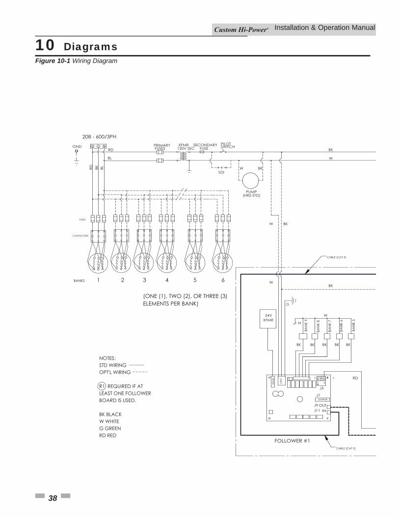
10 Diagrams
Installation & Operation Manual
Figure 10-1 Wiring Diagram
RD BK BL
PILOTSWITCH120V SEC
BL
RD FUSESPRIMARY
FUSESECONDARY
208 - 600/3PH
PUMP
GND
1 2 3 4 5
120V
24V
N
W
J7
J3
W
BK
BKW
OUTIN
W BK
BLK
BLK
RED
RED
BK
RD
J51 4
J9J11
CONTACTORS
BANKS 1 2 3 4 6
(ONE (1), TWO (2), OR THREE (3)ELEMENTS PER BANK) G
BK BK BK
BAN
K 9
NOTES:STD WIRINGOPT'L WIRING
R1 REQUIRED IF AT LEAST ONE FOLLOWERBOARD IS USED.
BK BLACKW WHITEG GREENRD RED
SDI
CABLE (CAT 5)
CABLE (CAT 5)
5
BKW
FUSES
BK
BAN
K 8
BAN
K 7
BAN
K 6
BAN
K 5
JUMPER
38
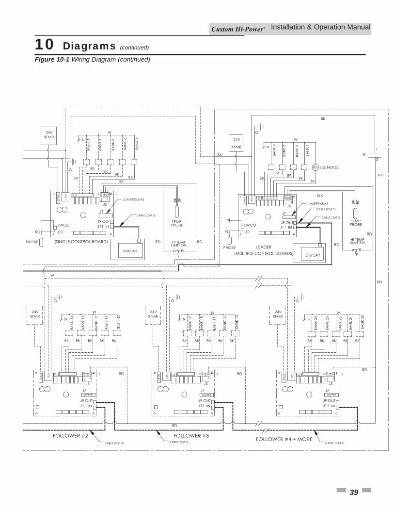
10 Diagrams (continued)
Installation & Operation Manual
Figure 10-1 Wiring Diagram (continued)
39
1 2 3 4 5
120V
24V
N
G
W
BK
RD
BKBK
J7
J3
1 2 3 4 5
24V
N
W
J7
J3 1 2 3 4 5
24V
N
J7
J3 1 2 3 4 5
24V
N
J7
J3
G G G
120V
120V
120V
W
OUTIN
OUTIN
OUTIN
OUTIN
BLK
BLK
RED
RED
BLK
BLK
RED
RED
BLK
BLK
RED
RED
BLK
BLK
RED
RED
HI TEMPLIMIT SW.
RD
RDRDRD
RD
RD
J5
J5 J5 J5
1 4
RD
1 41 41 4
J9J11
J9J11
J9J11
J9J11
TEMPPROBE
BAN
K 10
BAN
K 11
BAN
K 12
BAN
K 13
BAN
K 14
LEADER(MULTIPLE CONTROL BOARDS)DISPLAY
J10
PROBE (SINGLE CONTROL BOARD)
JUMPER
CABLE (CAT 5) CABLE (CAT 5) CABLE (CAT 5)
CABLE (CAT 5)
LWCO
JUMPER/BMS
BKBK BK
BKBK
BK
BKBK
BKBK
TEMPPROBE
SEE NOTES
J11J9
RD
4 1
J5
DISPLAY
LIMIT SW.HI TEMP
RED
RED
BLK
BLK
INOUT
J7
BK BK
R1
BLK
W
N
24V
120V 5 4 3 2 1
G
KB KB KB KB KB
W
BAN
K 19
BAN
K 18
BAN
K 17
BAN
K 16
BAN
K 15
KB KB KB KB KB
BAN
K 24
W
BAN
K 23
BAN
K 22
BAN
K 21
BAN
K 20
KB KB KB KB KB
RD
BAN
K 1
BAN
K 2
BAN
K 3
BAN
K 4
BAN
K 1
BAN
K 2
BAN
K 3
BAN
K 4
BAN
K 5
1R1
3
RD
BK
BK
J3
JUMPER JUMPER
CABLE (CAT 5)
CABLE (CAT 5)
LWCO
PROBE
RD J10
JUMPER/BMS

Revision Notes: Revision A (PCP# 3000005344 / CN# 500005576) initial release.
MM #100278842_DIR #2000537422_Rev A12/16