Embed Size (px)
Citation preview
TAIE TAIWAN INSTRUMENT & CONTROL CO., LTD
COMMUNICATION MANUAL DIGITAL PID CONTROLLER
FY100 FY101 FY400
FY600 FY700 FY800 FY900
February, 2007
FY_COMM_EN_V1

Contents 1 Set up of the controller...........................................................................................1 2 System Configuration ............................................................................................2
2.1 RS485 Communication System .................................................................2 2.2 RS232 Communication System .................................................................2
3 Wiring Connection.................................................................................................3 3.1 RS485 Communication Wiring..................................................................3 3.2 RS232 Communication Wiring..................................................................3
4 MODBUS RTU Protocol .......................................................................................4 4.1 Message Configuration ..............................................................................4 4.2 ID Number (Slave Address).......................................................................4 4.3 Function Code............................................................................................4 4.4 Data ............................................................................................................4 4.5 Error Check CRC.......................................................................................4 4.6 Abnormal Code..........................................................................................5 4.7 Message example of RTU mode ................................................................5
4.7.1 Reading ( Read PV from slave controller 1)..................................5 4.7.2 Setting (Set SV = 10.0 to slave controller 1) .................................5 4.7.3 Setting (Set SV = 10.0 and OUTL=100.0 to slave controller 1)....6
5 MODBUS ASCII Protocol.....................................................................................7 5.1 Message Configuration ..............................................................................7 5.2 ID Number(Slave Address)........................................................................7 5.3 Function Code............................................................................................7 5.4 Data ............................................................................................................7 5.5 Error Check LRC .......................................................................................7 5.6 Abnormal Code..........................................................................................8 5.7 Message example of ASCII mode..............................................................8
5.7.1 Setting (Set SV = 10.0 to slave controller 1) .................................8 5.7.2 Setting (Set SV = 10.0 and OUTL=100.0 to slave controller 1)....9
6 TAIE Protocol ......................................................................................................10 6.1 Message Configuration ............................................................................10 6.2 Command.................................................................................................10 6.3 ID Number ...............................................................................................10 6.4 Register Address ......................................................................................10 6.5 Data ..........................................................................................................10 6.6 Check Sum............................................................................................... 11 6.7 Message example of TAIE Protocol ........................................................ 11
6.7.1 Read ( Read PV from slave controller 1)..................................... 11 6.7.2 Modify ( Modify SV = 10.0 to slave controller 1)....................... 11 6.7.3 Write ( Write SV = 100.0 to slave controller 1) .......................... 11
7 Register Map........................................................................................................12

1 Set up of the controller
FY400/600/700/800/900 COMMUNICATION MANUAL 1
1 Set up of the controller
Press SET + key 3 seconds to configure parameters in Level 3
Character Name , Functions and Setting range Default
Protocol Selection
: MODBUS RTU Protocol
: MODBUS ASCII Protocol
: TAIE Protocol
Communication Bits
: Odd parity , Data bits = 8 , Stop Bit = 1
:Odd parity , Data bits = 8 , Stop Bit = 2
: Even parity , Data bits = 8 , Stop Bit = 1
: Even parity , Data bits = 8 , Stop Bit = 2
ID Number
Range : 0 ~ 255
Communication Baud rate
: 2400 bps
: 4800 bps
: 9600 bps
: 19200 bps
: 38400 bps
When parameter or was changed, always turn on the power
again. Otherwise, no communication is performed by using the changed value.
2 System Configuration
2 FY400/600/700/800/900 COMMUNICATION MANUAL
2 System Configuration 2.1 RS485 Communication System
HMI
(RS-485)
PLCContoller
IDNO : 2
Controller
IDNO : 3
Controller
IDNO : 4
Controller
IDNO : 32…………
Figure: 2.1-1
PLC
(RS-485)Controller
IDNO : 1
Controller
IDNO : 2
Controller
IDNO : 3
Controller
IDNO : 32…………
Figure: 2.1-2
Controller
IDNO : 1
HOST COMPUTER
(RS-485)Controller
IDNO : 2
Controller
IDNO : 3
Controller
IDNO : 32…………
Figure: 2.1-3
Controller
IDNO : 1
PC
Controller
IDNO : 2
Controller
IDNO : 3
Controller
IDNO : 32…………
Communication Converter
RS232 RS485
(RS-232)
Figure: 2.1-4
2.2 RS232 Communication System
Controller
IDNO : 1
PC
(RS-232)
Figure: 2.2-1
3 Wiring Connection
FY400/600/700/800/900 COMMUNICATION MANUAL 3
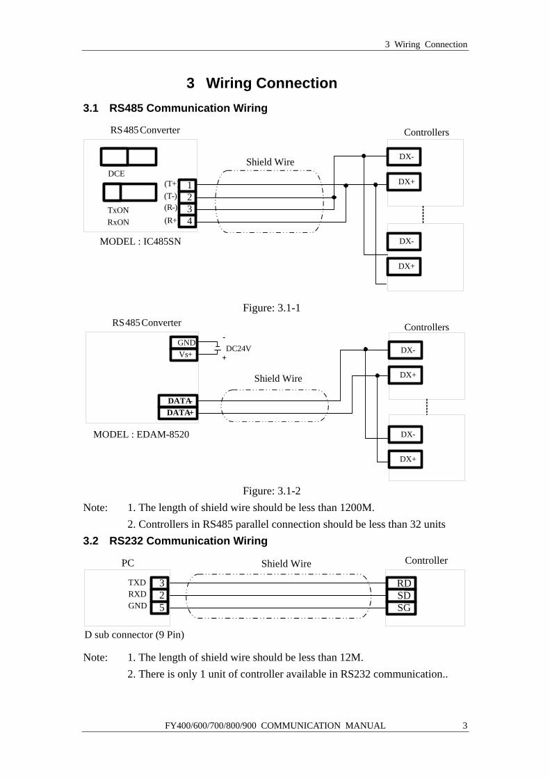
3 Wiring Connection 3.1 RS485 Communication Wiring
RS485 Converter
DCE
TxONRxON
Controllers
1234
DX +
DX -
(R-)(T-)(T+)
(R+)
Shield Wire
MODEL : IC485SN
DX +
DX -
Figure: 3.1-1 RS485 Converter
GNDVs+
DATA-DATA+
DC24V+
-
Shield Wire
Controllers
DX +
DX -
DX +
DX -MODEL : EDAM-8520
Figure: 3.1-2
Note: 1. The length of shield wire should be less than 1200M. 2. Controllers in RS485 parallel connection should be less than 32 units 3.2 RS232 Communication Wiring
Controller
325GND
RXDTXD
Shield WirePC
RDSDSG
D sub connector (9 Pin) Note: 1. The length of shield wire should be less than 12M. 2. There is only 1 unit of controller available in RS232 communication..
4 MODBUS RTU Protocol
4 FY400/600/700/800/900 COMMUNICATION MANUAL
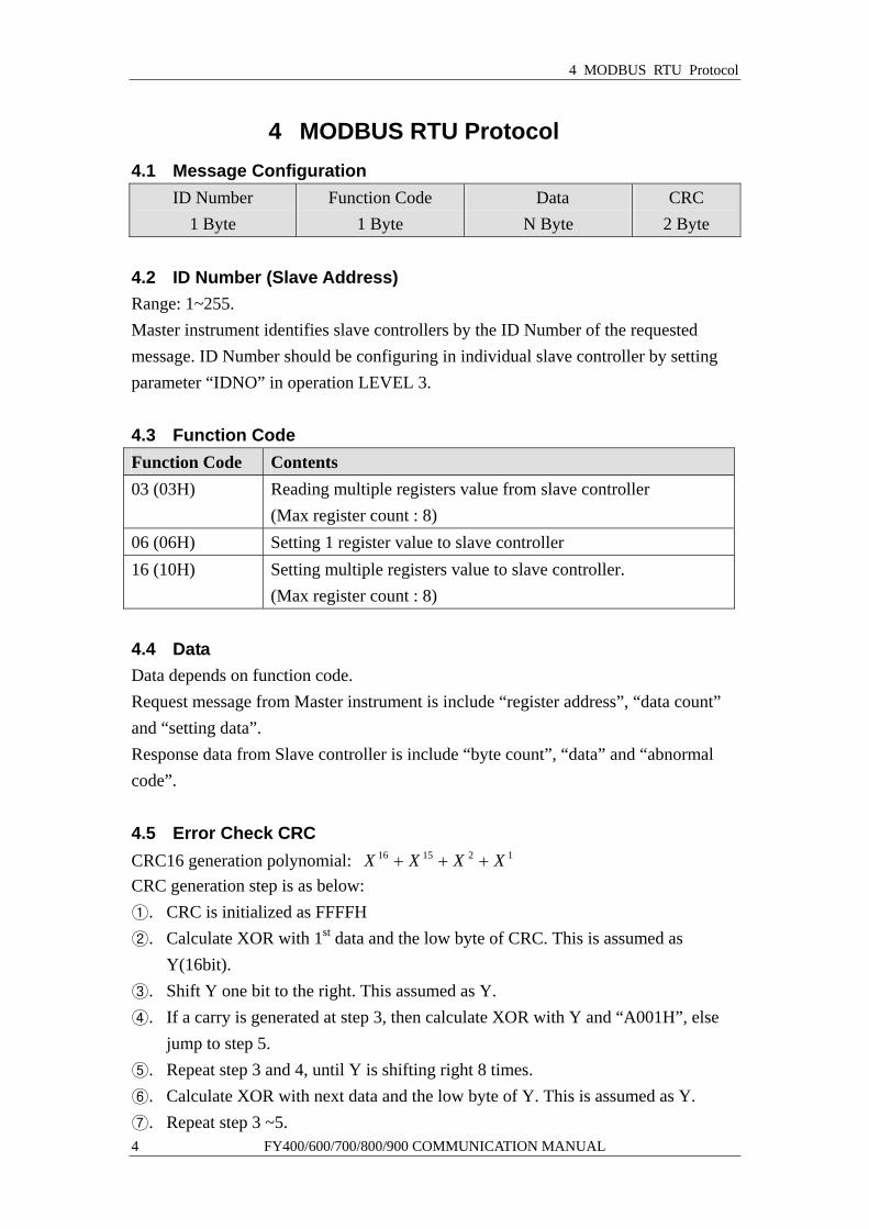
4 MODBUS RTU Protocol 4.1 Message Configuration
ID Number 1 Byte
Function Code 1 Byte
Data N Byte
CRC 2 Byte
4.2 ID Number (Slave Address) Range: 1~255. Master instrument identifies slave controllers by the ID Number of the requested message. ID Number should be configuring in individual slave controller by setting parameter “IDNO” in operation LEVEL 3. 4.3 Function Code Function Code Contents 03 (03H) Reading multiple registers value from slave controller
(Max register count : 8) 06 (06H) Setting 1 register value to slave controller 16 (10H) Setting multiple registers value to slave controller.
(Max register count : 8) 4.4 Data Data depends on function code. Request message from Master instrument is include “register address”, “data count” and “setting data”. Response data from Slave controller is include “byte count”, “data” and “abnormal code”. 4.5 Error Check CRC CRC16 generation polynomial: 121516 XXXX +++ CRC generation step is as below: ①. CRC is initialized as FFFFH ②. Calculate XOR with 1st data and the low byte of CRC. This is assumed as
Y(16bit). ③. Shift Y one bit to the right. This assumed as Y. ④. If a carry is generated at step 3, then calculate XOR with Y and “A001H”, else
jump to step 5. ⑤. Repeat step 3 and 4, until Y is shifting right 8 times. ⑥. Calculate XOR with next data and the low byte of Y. This is assumed as Y. ⑦. Repeat step 3 ~5.
4 MODBUS RTU Protocol
FY400/600/700/800/900 COMMUNICATION MANUAL 5
⑧. Repeat step 3~5, until last data is processed. ⑨. Swap the low byte and high byte of Y. ⑩. CRC=Y 4.6 Abnormal Code Abnormal Code Contents 01 (01H) Illegal function code (Non-existent function code) 02 (02H) Illegal register address (Register address is out of range) 03 (03H) Illegal data value (Data value is out of setting range) 4.7 Message example of RTU mode 4.7.1 Reading ( Read PV from slave controller 1)
Request message from master instrument: ID Number
(01H)
Function Code
(03H)
Register Address (008AH)
Data Count
(0001H)
CRC
(A5E0H) Response data from slave controller in normal status (Assumed PV=100.0)
ID Number (01H)
Function Code(03H)
Byte Count (02H)
Data (03E8H)
CRC (B8FAH)
Response from slave controller in abnormal status (Assumed as illegal data value)
ID Number (01H)
Function Code(83H)
Error Code (03H)
CRC (0131H)
1 is set to the MSB of function code in abnormal status (83H). The abnormal code (03H) is returned as contents of error. 4.7.2 Setting (Set SV = 10.0 to slave controller 1)
Request message from master instrument: ID Number
(01H)
Function Code
(06H)
Register Address (0000H)
Setting Data
(0064H)
CRC
(8821H) Response message from slave controller in normal status (When SV = 10.0)
ID Number
(01H)
Function Code
(06H)
Register Address (0000H)
Setting Data
(0064H)
CRC
(8821H)
4 MODBUS RTU Protocol
6 FY400/600/700/800/900 COMMUNICATION MANUAL
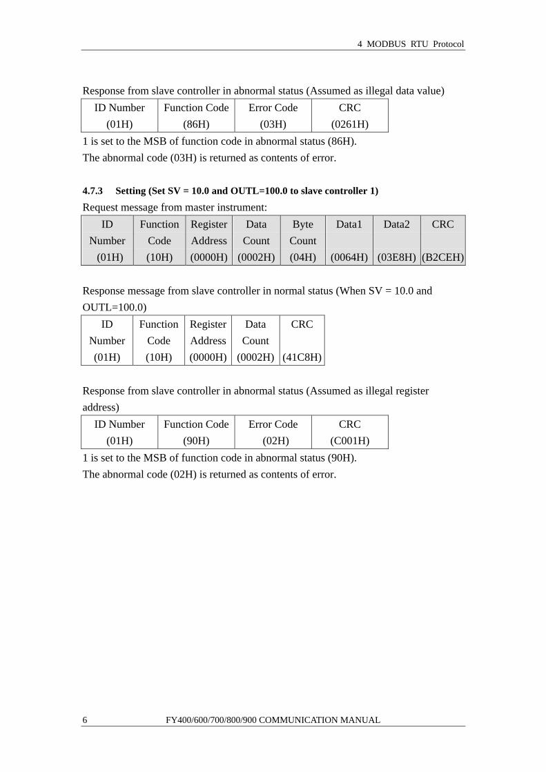
Response from slave controller in abnormal status (Assumed as illegal data value)
ID Number (01H)
Function Code(86H)
Error Code (03H)
CRC (0261H)
1 is set to the MSB of function code in abnormal status (86H). The abnormal code (03H) is returned as contents of error. 4.7.3 Setting (Set SV = 10.0 and OUTL=100.0 to slave controller 1)
Request message from master instrument: ID
Number (01H)
Function Code (10H)
Register Address(0000H)
Data Count
(0002H)
Byte Count (04H)
Data1
(0064H)
Data2
(03E8H)
CRC
(B2CEH) Response message from slave controller in normal status (When SV = 10.0 and OUTL=100.0)
ID Number (01H)
Function Code (10H)
Register Address(0000H)
Data Count
(0002H)
CRC
(41C8H) Response from slave controller in abnormal status (Assumed as illegal register address)
ID Number (01H)
Function Code(90H)
Error Code (02H)
CRC (C001H)
1 is set to the MSB of function code in abnormal status (90H). The abnormal code (02H) is returned as contents of error.
5 MODBUS ASCII Protocol
FY400/600/700/800/900 COMMUNICATION MANUAL 7
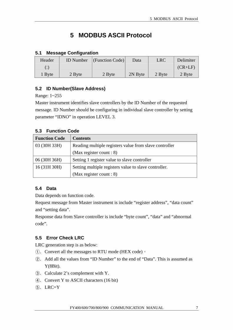
5 MODBUS ASCII Protocol 5.1 Message Configuration
Header (:)
1 Byte
ID Number
2 Byte
(Function Code)
2 Byte
Data
2N Byte
LRC
2 Byte
Delimiter(CR+LF)
2 Byte 5.2 ID Number(Slave Address) Range: 1~255 Master instrument identifies slave controllers by the ID Number of the requested message. ID Number should be configuring in individual slave controller by setting parameter “IDNO” in operation LEVEL 3. 5.3 Function Code Function Code Contents 03 (30H 33H) Reading multiple registers value from slave controller
(Max register count : 8) 06 (30H 36H) Setting 1 register value to slave controller 16 (31H 30H) Setting multiple registers value to slave controller.
(Max register count : 8) 5.4 Data Data depends on function code. Request message from Master instrument is include “register address”, “data count” and “setting data”. Response data from Slave controller is include “byte count”, “data” and “abnormal code”. 5.5 Error Check LRC LRC generation step is as below: ①. Convert all the messages to RTU mode (HEX code)。 ②. Add all the values from “ID Number” to the end of “Data”. This is assumed as
Y(8Bit). ③. Calculate 2’s complement with Y. ④. Convert Y to ASCII characters (16 bit) ⑤. LRC=Y
5 MODBUS ASCII Protocol
8 FY400/600/700/800/900 COMMUNICATION MANUAL
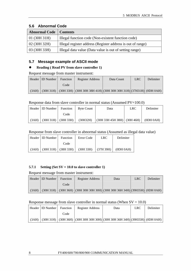
5.6 Abnormal Code Abnormal Code Contents 01 (30H 31H) Illegal function code (Non-existent function code) 02 (30H 32H) Illegal register address (Register address is out of range) 03 (30H 33H) Illegal data value (Data value is out of setting range) 5.7 Message example of ASCII mode
Reading ( Read PV from slave controller 1)
Request message from master instrument: Header
(3AH)
ID Number
(30H 31H)
Function
Code
(30H 33H)
Register Address
(30H 30H 38H 41H)
Data Count
(30H 30H 30H 31H)
LRC
(37H31H)
Delimiter
(0DH 0AH)
Response data from slave controller in normal status (Assumed PV=100.0) Header
(3AH)
ID Number
(30H 31H)
Function
Code
(30H 33H)
Byte Count
(30H32H)
Data
(30H 33H 45H 38H)
LRC
(30H 46H)
Delimiter
(0DH 0AH)
Response from slave controller in abnormal status (Assumed as illegal data value) Header
(3AH)
ID Number
(30H 31H)
Function
Code
(38H 33H)
Error Code
(30H 33H)
LRC
(37H 39H)
Delimiter
(0DH 0AH)
5.7.1 Setting (Set SV = 10.0 to slave controller 1)
Request message from master instrument: Header
(3AH)
ID Number
(30H 31H)
Function
Code
(30H 36H)
Register Address
(30H 30H 30H 30H)
Data
(30H 30H 36H 34H)
LRC
(39H35H)
Delimiter
(0DH 0AH)
Response message from slave controller in normal status (When SV = 10.0) Header
(3AH)
ID Number
(30H 31H)
Function
Code
(30H 36H)
Register Address
(30H 30H 30H 30H)
Data
(30H 30H 36H 34H)
LRC
(39H35H)
Delimiter
(0DH 0AH)
5 MODBUS ASCII Protocol
FY400/600/700/800/900 COMMUNICATION MANUAL 9
Response from slave controller in abnormal status (Assumed as illegal data value) Header
(3AH)
ID Number
(30H 31H)
Function
Code
(38H 36H)
Error Code
(30H 33H)
LRC
(37H 36H)
Delimiter
(0DH 0AH)
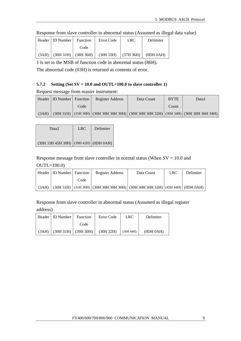
1 is set to the MSB of function code in abnormal status (86H). The abnormal code (03H) is returned as contents of error. 5.7.2 Setting (Set SV = 10.0 and OUTL=100.0 to slave controller 1)
Request message from master instrument: Header
(3AH)
ID Number
(30H 31H)
Function
Code
(31H 30H)
Register Address
(30H 30H 30H 30H)
Data Count
(30H 30H 30H 32H)
BYTE
Count
(30H 34H)
Data1
(30H 30H 36H 34H)
Data2
(30H 33H 45H 38H)
LRC
(39H 41H)
Delimiter
(0DH 0AH)
Response message from slave controller in normal status (When SV = 10.0 and OUTL=100.0) Header
(3AH)
ID Number
(30H 31H)
Function
Code
(31H 30H)
Register Address
(30H 30H 30H 30H)
Data Count
(30H 30H 30H 32H)
LRC
(45H 44H)
Delimiter
(0DH 0AH)
Response from slave controller in abnormal status (Assumed as illegal register address) Header
(3AH)
ID Number
(30H 31H)
Function
Code
(39H 30H)
Error Code
(30H 32H)
LRC
(36H 44H)
Delimiter
(0DH 0AH)
6 TAIE Protocol
10 FY400/600/700/800/900 COMMUNICATION MANUAL
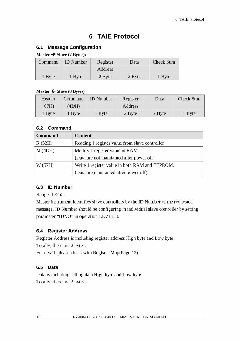
6 TAIE Protocol 6.1 Message Configuration Master Slave (7 Bytes):
Command
1 Byte
ID Number
1 Byte
Register Address 2 Byte
Data
2 Byte
Check Sum
1 Byte Master Slave (8 Bytes)
Header (07H) 1 Byte
Command (4DH) 1 Byte
ID Number
1 Byte
Register Address 2 Byte
Data
2 Byte
Check Sum
1 Byte 6.2 Command Command Contents R (52H) Reading 1 register value from slave controller M (4DH) Modify 1 register value in RAM.
(Data are not maintained after power off) W (57H) Write 1 register value in both RAM and EEPROM.
(Data are maintained after power off) 6.3 ID Number Range: 1~255. Master instrument identifies slave controllers by the ID Number of the requested message. ID Number should be configuring in individual slave controller by setting parameter “IDNO” in operation LEVEL 3.
6.4 Register Address Register Address is including register address High byte and Low byte. Totally, there are 2 bytes. For detail, please check with Register Map(Page:12)
6.5 Data Data is including setting data High byte and Low byte. Totally, there are 2 bytes.
6 TAIE Protocol
FY400/600/700/800/900 COMMUNICATION MANUAL 11
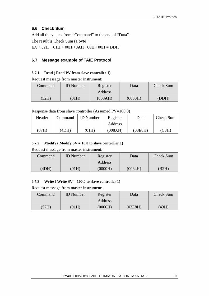
6.6 Check Sum Add all the values from “Command” to the end of “Data”. The result is Check Sum (1 byte). EX:52H + 01H + 00H +8AH +00H +00H = DDH
6.7 Message example of TAIE Protocol 6.7.1 Read ( Read PV from slave controller 1)
Request message from master instrument: Command
(52H)
ID Number
(01H)
Register Address (008AH)
Data
(0000H)
Check Sum
(DDH) Response data from slave controller (Assumed PV=100.0)
Header
(07H)
Command
(4DH)
ID Number
(01H)
Register Address (008AH)
Data
(03E8H)
Check Sum
(C3H)
6.7.2 Modify ( Modify SV = 10.0 to slave controller 1)
Request message from master instrument: Command
(4DH)
ID Number
(01H)
Register Address (0000H)
Data
(0064H)
Check Sum
(B2H)
6.7.3 Write ( Write SV = 100.0 to slave controller 1)
Request message from master instrument: Command
(57H)
ID Number
(01H)
Register Address (0000H)
Data
(03E8H)
Check Sum
(43H)
7 Register Map
12 FY400/600/700/800/900 COMMUNICATION MANUAL
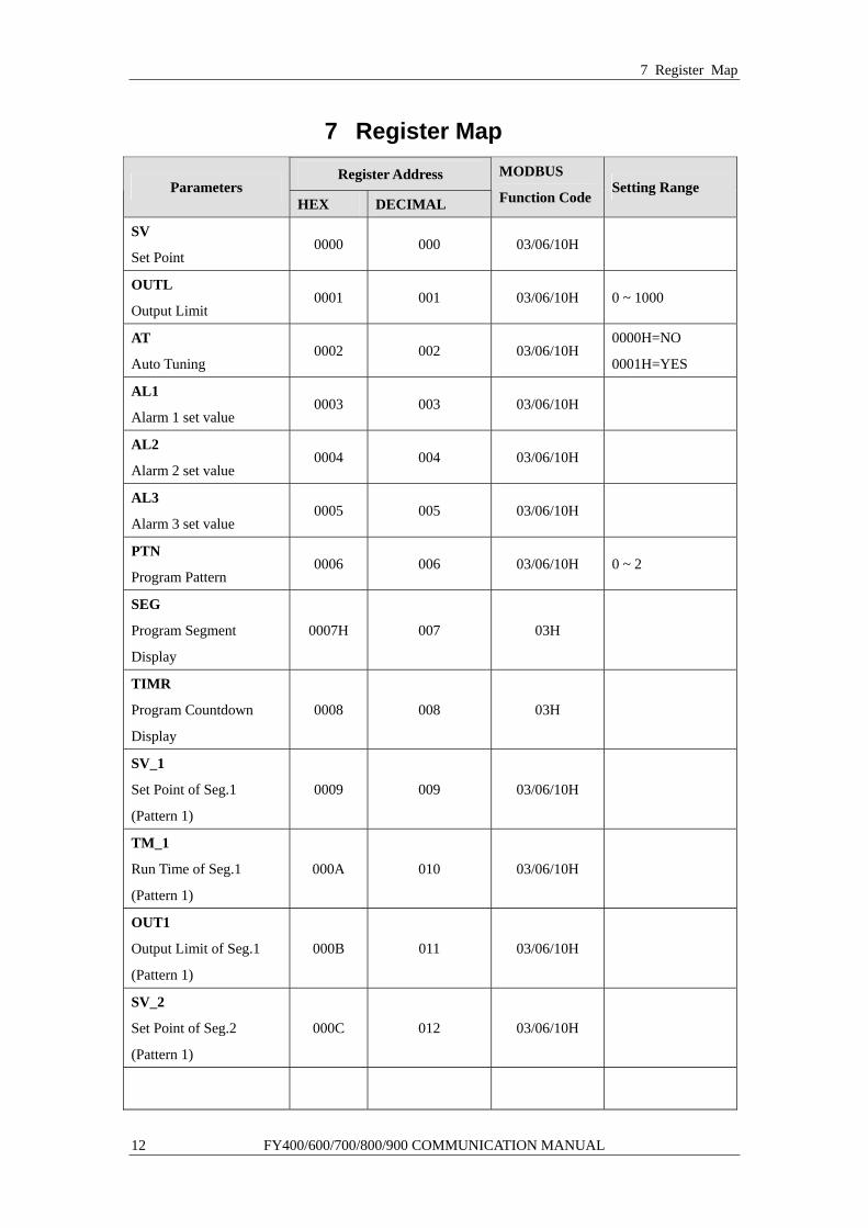
7 Register Map Register Address
Parameters HEX DECIMAL
MODBUS
Function CodeSetting Range
SV
Set Point 0000 000 03/06/10H
OUTL
Output Limit 0001 001 03/06/10H 0 ~ 1000
AT
Auto Tuning 0002 002 03/06/10H
0000H=NO
0001H=YES
AL1
Alarm 1 set value 0003 003 03/06/10H
AL2
Alarm 2 set value 0004 004 03/06/10H
AL3
Alarm 3 set value 0005 005 03/06/10H
PTN
Program Pattern 0006 006 03/06/10H 0 ~ 2
SEG
Program Segment
Display
0007H 007 03H
TIMR
Program Countdown
Display
0008 008 03H
SV_1
Set Point of Seg.1
(Pattern 1)
0009 009 03/06/10H
TM_1
Run Time of Seg.1
(Pattern 1)
000A 010 03/06/10H
OUT1
Output Limit of Seg.1
(Pattern 1)
000B 011 03/06/10H
SV_2
Set Point of Seg.2
(Pattern 1)
000C 012 03/06/10H

7 Register Map
FY400/600/700/800/900 COMMUNICATION MANUAL 13
Register Address Parameters
HEX DECIMAL
MODBUS
Function CodeSetting Range
TM_2
Run Time of Seg.2
(Pattern 1)
000D 013 03/06/10H
OUT2
Output Limit of Seg.2
(Pattern 1)
000E 014 03/06/10H
SV_3
Set Point of Seg.3
(Pattern 1)
000F 015 03/06/10H
TM_3
Run Time of Seg.3
(Pattern 1)
0010 016 03/06/10H
OUT3
Output Limit of Seg.3
(Pattern 1)
0011 017 03/06/10H
SV_4
Set Point of Seg.4
(Pattern 1)
0012 018 03/06/10H
TM_4
Run Time of Seg.4
(Pattern 1)
0013 019 03/06/10H
OUT4
Output Limit of Seg.4
(Pattern 1)
0014 020 03/06/10H
SV_5
Set Point of Seg.5
(Pattern 1)
0015 021 03/06/10H
TM_5
Run Time of Seg.5
(Pattern 1)
0016 022 03/06/10H
OUT5
Output Limit of Seg.5
(Pattern 1)
0017 023 03/06/10H
SV_6
Set Point of Seg.6
(Pattern 1)
0018 024 03/06/10H

7 Register Map
14 FY400/600/700/800/900 COMMUNICATION MANUAL
Register Address Parameters
HEX DECIMAL
MODBUS
Function CodeSetting Range
TM_6
Run Time of Seg.6
(Pattern 1)
0019 025 03/06/10H
OUT6
Output Limit of Seg.6
(Pattern 1)
001A 026 03/06/10H
SV_7
Set Point of Seg.7
(Pattern 1)
001B 027 03/06/10H
TM_7
Run Time of Seg.7
(Pattern 1)
001C 028 03/06/10H
OUT7
Output Limit of Seg.7
(Pattern 1)
001D 029 03/06/10H
SV_8
Set Point of Seg.8
(Pattern 1)
001E 030 03/06/10H
TM_8
Run Time of Seg.8
(Pattern 1)
001F 031 03/06/10H
OUT8
Output Limit of Seg.8
(Pattern 1)
0020 032 03/06/10H
SV_12
Set Point of Seg.1
(Pattern 2)
0021 033 03/06/10H
TM_12
Run Time of Seg.1
(Pattern 2)
0022 034 03/06/10H
OUT12
Output Limit of Seg.1
(Pattern 2)
0023 035 03/06/10H
SV_22
Set Point of Seg.2
(Pattern 2)
0024 036 03/06/10H
7 Register Map
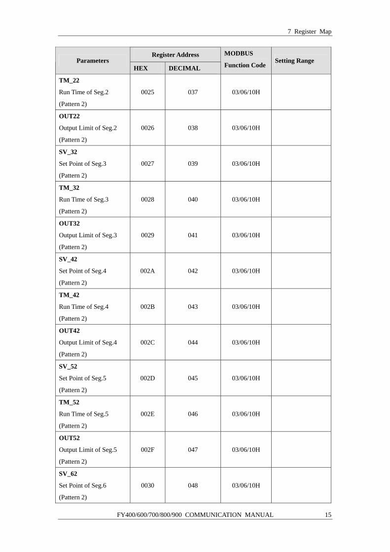
FY400/600/700/800/900 COMMUNICATION MANUAL 15
Register Address Parameters
HEX DECIMAL
MODBUS
Function CodeSetting Range
TM_22
Run Time of Seg.2
(Pattern 2)
0025 037 03/06/10H
OUT22
Output Limit of Seg.2
(Pattern 2)
0026 038 03/06/10H
SV_32
Set Point of Seg.3
(Pattern 2)
0027 039 03/06/10H
TM_32
Run Time of Seg.3
(Pattern 2)
0028 040 03/06/10H
OUT32
Output Limit of Seg.3
(Pattern 2)
0029 041 03/06/10H
SV_42
Set Point of Seg.4
(Pattern 2)
002A 042 03/06/10H
TM_42
Run Time of Seg.4
(Pattern 2)
002B 043 03/06/10H
OUT42
Output Limit of Seg.4
(Pattern 2)
002C 044 03/06/10H
SV_52
Set Point of Seg.5
(Pattern 2)
002D 045 03/06/10H
TM_52
Run Time of Seg.5
(Pattern 2)
002E 046 03/06/10H
OUT52
Output Limit of Seg.5
(Pattern 2)
002F 047 03/06/10H
SV_62
Set Point of Seg.6
(Pattern 2)
0030 048 03/06/10H
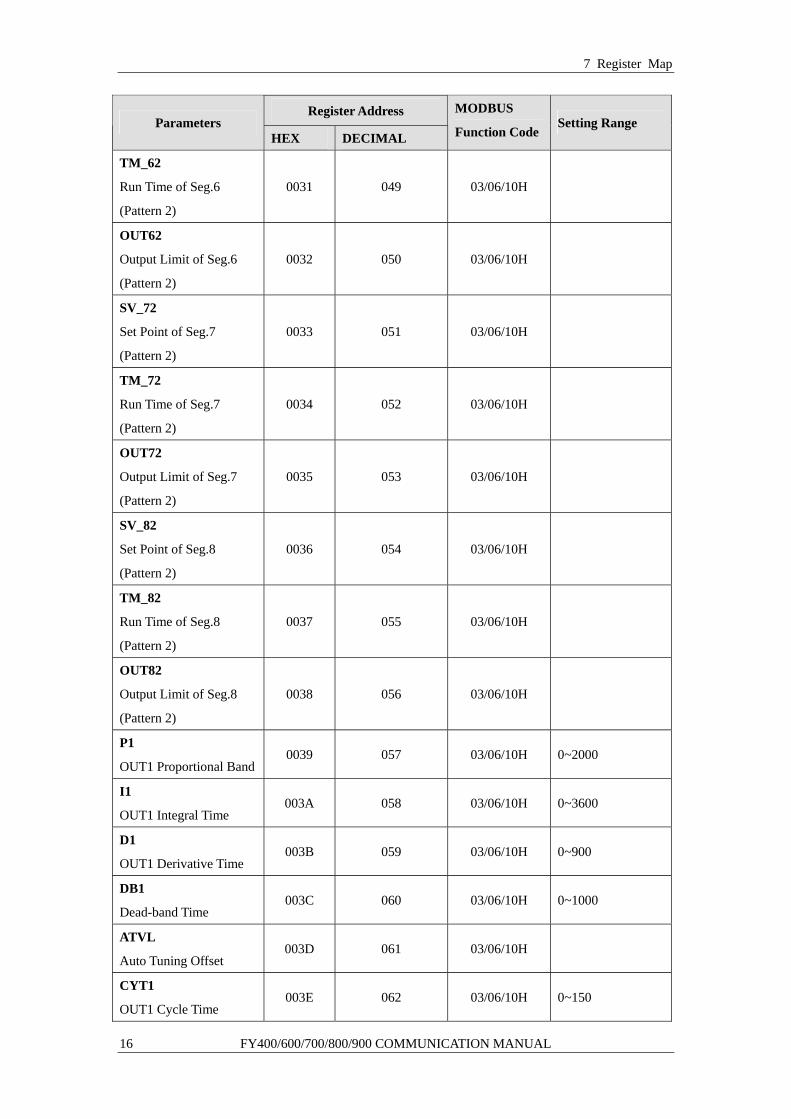
7 Register Map
16 FY400/600/700/800/900 COMMUNICATION MANUAL
Register Address Parameters
HEX DECIMAL
MODBUS
Function CodeSetting Range
TM_62
Run Time of Seg.6
(Pattern 2)
0031 049 03/06/10H
OUT62
Output Limit of Seg.6
(Pattern 2)
0032 050 03/06/10H
SV_72
Set Point of Seg.7
(Pattern 2)
0033 051 03/06/10H
TM_72
Run Time of Seg.7
(Pattern 2)
0034 052 03/06/10H
OUT72
Output Limit of Seg.7
(Pattern 2)
0035 053 03/06/10H
SV_82
Set Point of Seg.8
(Pattern 2)
0036 054 03/06/10H
TM_82
Run Time of Seg.8
(Pattern 2)
0037 055 03/06/10H
OUT82
Output Limit of Seg.8
(Pattern 2)
0038 056 03/06/10H
P1
OUT1 Proportional Band 0039 057 03/06/10H 0~2000
I1
OUT1 Integral Time 003A 058 03/06/10H 0~3600
D1
OUT1 Derivative Time 003B 059 03/06/10H 0~900
DB1
Dead-band Time 003C 060 03/06/10H 0~1000
ATVL
Auto Tuning Offset 003D 061 03/06/10H
CYT1
OUT1 Cycle Time 003E 062 03/06/10H 0~150
7 Register Map
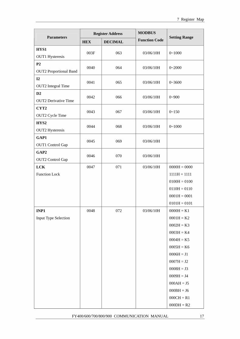
FY400/600/700/800/900 COMMUNICATION MANUAL 17
Register Address Parameters
HEX DECIMAL
MODBUS
Function CodeSetting Range
HYS1
OUT1 Hysteresis 003F 063 03/06/10H 0~1000
P2
OUT2 Proportional Band 0040 064 03/06/10H 0~2000
I2
OUT2 Integral Time 0041 065 03/06/10H 0~3600
D2
OUT2 Derivative Time 0042 066 03/06/10H 0~900
CYT2
OUT2 Cycle Time 0043 067 03/06/10H 0~150
HYS2
OUT2 Hysteresis 0044 068 03/06/10H 0~1000
GAP1
OUT1 Control Gap 0045 069 03/06/10H
GAP2
OUT2 Control Gap 0046 070 03/06/10H
LCK
Function Lock
0047 071 03/06/10H 0000H = 0000
1111H = 1111
0100H = 0100
0110H = 0110
0001H = 0001
0101H = 0101
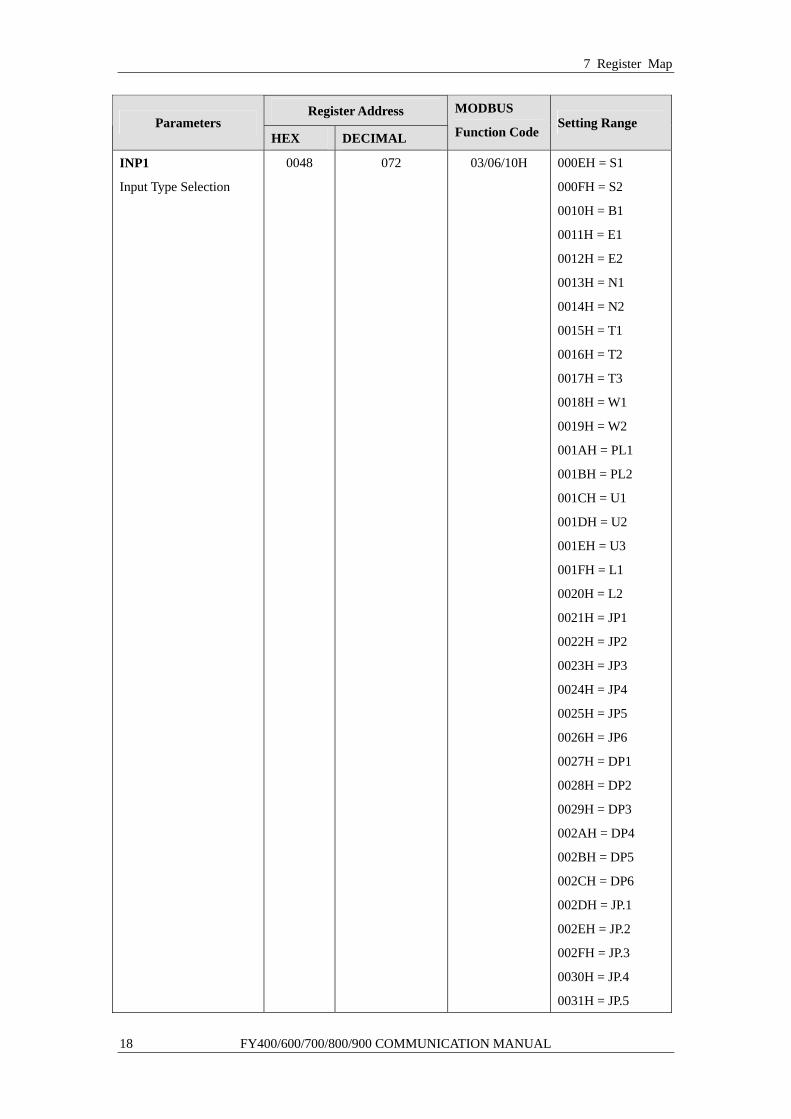
INP1
Input Type Selection
0048
072
03/06/10H
0000H = K1
0001H = K2
0002H = K3
0003H = K4
0004H = K5
0005H = K6
0006H = J1
0007H = J2
0008H = J3
0009H = J4
000AH = J5
000BH = J6
000CH = R1
000DH = R2
7 Register Map
18 FY400/600/700/800/900 COMMUNICATION MANUAL
Register Address Parameters
HEX DECIMAL
MODBUS
Function CodeSetting Range
INP1
Input Type Selection
0048 072 03/06/10H 000EH = S1
000FH = S2
0010H = B1
0011H = E1
0012H = E2
0013H = N1
0014H = N2
0015H = T1
0016H = T2
0017H = T3
0018H = W1
0019H = W2
001AH = PL1
001BH = PL2
001CH = U1
001DH = U2
001EH = U3
001FH = L1
0020H = L2
0021H = JP1
0022H = JP2
0023H = JP3
0024H = JP4
0025H = JP5
0026H = JP6
0027H = DP1
0028H = DP2
0029H = DP3
002AH = DP4
002BH = DP5
002CH = DP6
002DH = JP.1
002EH = JP.2
002FH = JP.3
0030H = JP.4
0031H = JP.5
7 Register Map
FY400/600/700/800/900 COMMUNICATION MANUAL 19
Register Address Parameters
HEX DECIMAL
MODBUS
Function CodeSetting Range
INP1
Input Type Selection
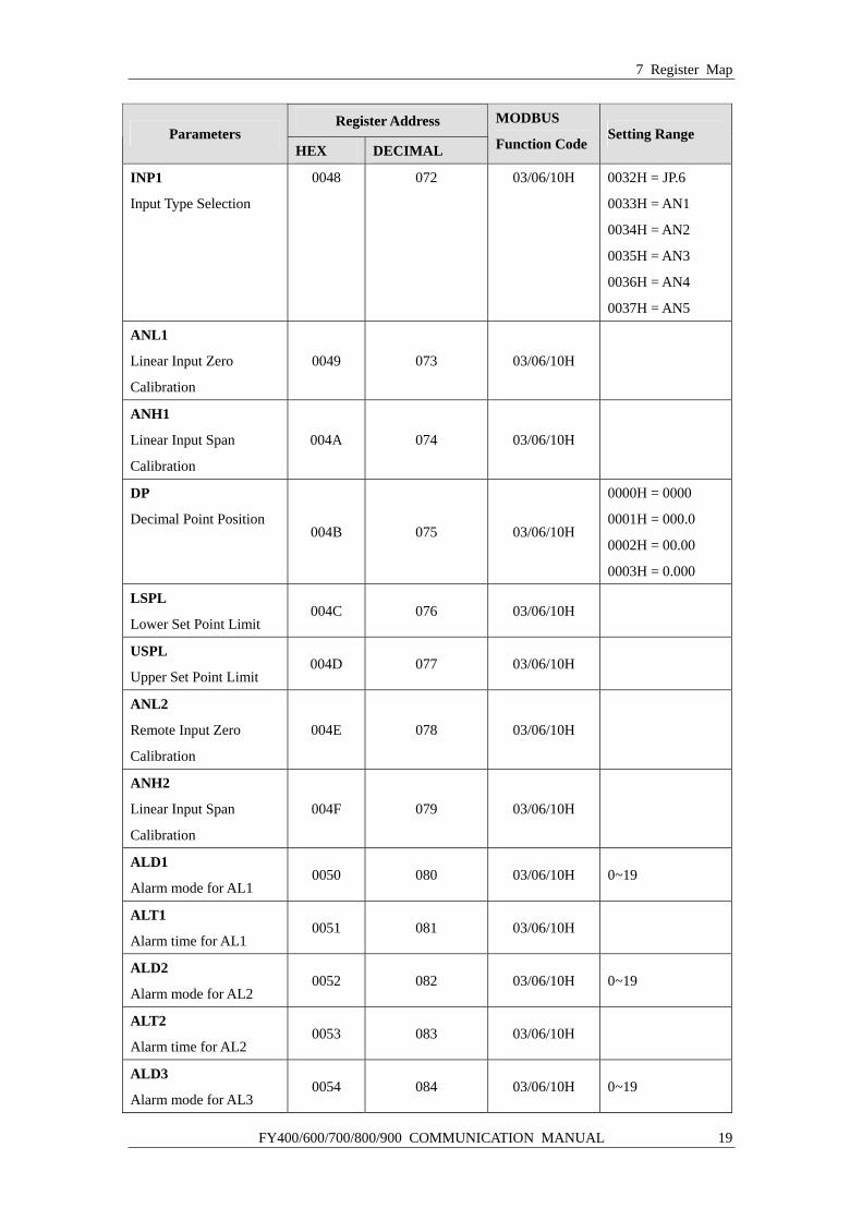
0048 072 03/06/10H 0032H = JP.6
0033H = AN1
0034H = AN2
0035H = AN3
0036H = AN4
0037H = AN5
ANL1
Linear Input Zero
Calibration
0049 073 03/06/10H
ANH1
Linear Input Span
Calibration
004A 074 03/06/10H
DP
Decimal Point Position 004B 075 03/06/10H
0000H = 0000
0001H = 000.0
0002H = 00.00
0003H = 0.000
LSPL
Lower Set Point Limit 004C 076 03/06/10H
USPL
Upper Set Point Limit 004D 077 03/06/10H
ANL2
Remote Input Zero
Calibration
004E 078 03/06/10H
ANH2
Linear Input Span
Calibration
004F 079 03/06/10H
ALD1
Alarm mode for AL1 0050 080 03/06/10H 0~19
ALT1
Alarm time for AL1 0051 081 03/06/10H
ALD2
Alarm mode for AL2 0052 082 03/06/10H 0~19
ALT2
Alarm time for AL2 0053 083 03/06/10H
ALD3
Alarm mode for AL3 0054 084 03/06/10H 0~19
7 Register Map
20 FY400/600/700/800/900 COMMUNICATION MANUAL
Register Address Parameters
HEX DECIMAL
MODBUS
Function CodeSetting Range
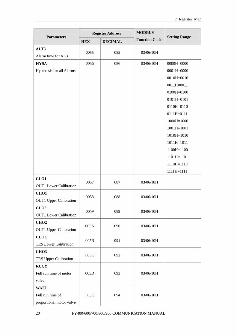
ALT3
Alarm time for AL3 0055 085 03/06/10H
HYSA
Hysteresis for all Alarms
0056 086 03/06/10H 0000H=0000
0001H=0000
0010H=0010
0011H=0011
0100H=0100
0101H=0101
0110H=0110
0111H=0111
1000H=1000
1001H=1001
1010H=1010
1011H=1011
1100H=1100
1101H=1101
1110H=1110
1111H=1111
CLO1
OUT1 Lower Calibration 0057 087 03/06/10H
CHO1
OUT1 Upper Calibration 0058 088 03/06/10H
CLO2
OUT1 Lower Calibration 0059 089 03/06/10H
CHO2
OUT1 Upper Calibration 005A 090 03/06/10H
CLO3
TRS Lower Calibration 005B 091 03/06/10H
CHO3
TRS Upper Calibration 005C 092 03/06/10H
RUCY
Full run time of motor
valve
005D 093 03/06/10H
WAIT
Full run time of
proportional motor valve
005E 094 03/06/10H
7 Register Map
FY400/600/700/800/900 COMMUNICATION MANUAL 21
Register Address Parameters
HEX DECIMAL
MODBUS
Function CodeSetting Range
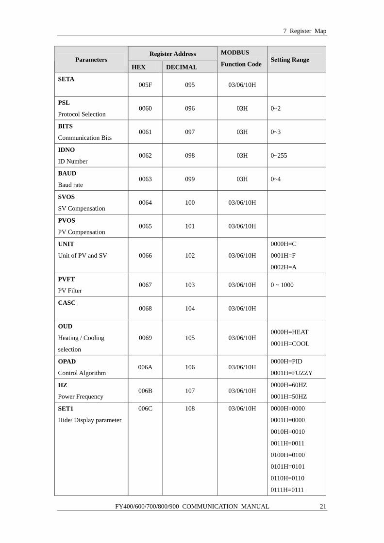
SETA
005F 095 03/06/10H
PSL
Protocol Selection 0060 096 03H 0~2
BITS
Communication Bits 0061 097 03H 0~3
IDNO
ID Number 0062 098 03H 0~255
BAUD
Baud rate 0063 099 03H 0~4
SVOS
SV Compensation 0064 100 03/06/10H
PVOS
PV Compensation 0065 101 03/06/10H
UNIT
Unit of PV and SV 0066 102 03/06/10H
0000H=C
0001H=F
0002H=A
PVFT
PV Filter 0067 103 03/06/10H 0 ~ 1000
CASC
0068 104 03/06/10H
OUD
Heating / Cooling
selection
0069 105 03/06/10H 0000H=HEAT
0001H=COOL
OPAD
Control Algorithm 006A 106 03/06/10H
0000H=PID
0001H=FUZZY
HZ
Power Frequency 006B 107 03/06/10H
0000H=60HZ
0001H=50HZ
SET1
Hide/ Display parameter
006C 108 03/06/10H 0000H=0000
0001H=0000
0010H=0010
0011H=0011
0100H=0100
0101H=0101
0110H=0110
0111H=0111

7 Register Map
22 FY400/600/700/800/900 COMMUNICATION MANUAL
Register Address Parameters
HEX DECIMAL
MODBUS
Function CodeSetting Range
SET1
Hide/ Display parameter
006C 108 03/06/10H 1000H=1000
1001H=1001
1010H=1010
1011H=1011
1100H=1100
1101H=1101
1110H=1110
1111H=1111
SET2
Hide/ Display parameter 006D 109 03/06/10H Same with SET1
SET3 Hide/ Display parameter 006E 110 03/06/10H Same with SET1
SET4 Hide/ Display parameter 006F 111 03/06/10H Same with SET1
SET5 Hide/ Display parameter 0070 112 03/06/10H Same with SET1
SET6 Hide/ Display parameter 0071 113 03/06/10H Same with SET1
SET7 Hide/ Display parameter 0072 114 03/06/10H Same with SET1
SET8 Hide/ Display parameter 0073 115 03/06/10H Same with SET1
SET9 Hide/ Display parameter 0074 116 03/06/10H Same with SET1
SET0 Hide/ Display parameter 0075 117 03/06/10H Same with SET1
INP2 Hide/ Display parameter 0076 118 03/06/10H 0 ~ 2
OUTY Output mode selection 0077 119 03/06/10H 0 ~ 5
7 Register Map
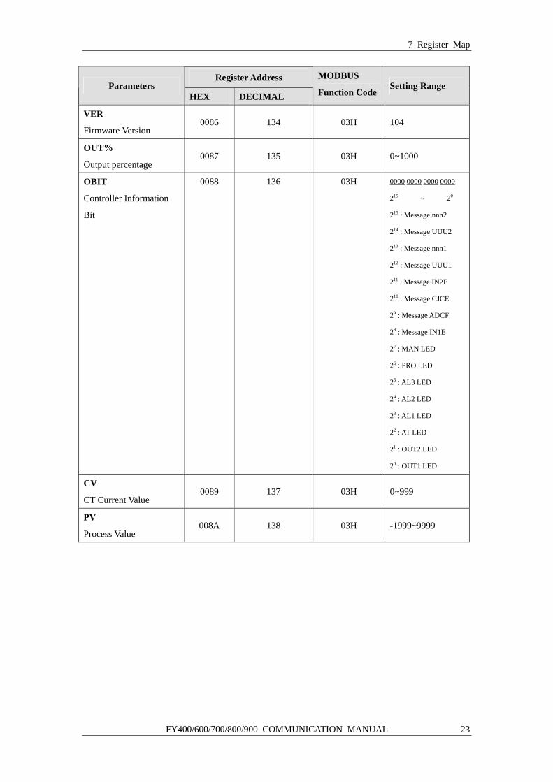
FY400/600/700/800/900 COMMUNICATION MANUAL 23
Register Address Parameters
HEX DECIMAL
MODBUS
Function CodeSetting Range
VER
Firmware Version 0086 134 03H 104
OUT%
Output percentage 0087 135 03H 0~1000
OBIT
Controller Information
Bit
0088 136
03H
0000 0000 0000 0000
215 ~ 20
215 : Message nnn2
214 : Message UUU2
213 : Message nnn1
212 : Message UUU1
211 : Message IN2E
210 : Message CJCE
29 : Message ADCF
28 : Message IN1E
27 : MAN LED
26 : PRO LED
25 : AL3 LED
24 : AL2 LED
23 : AL1 LED
22 : AT LED
21 : OUT2 LED
20 : OUT1 LED
CV
CT Current Value 0089 137 03H 0~999
PV
Process Value 008A 138 03H -1999~9999

TAIE TAIWAN INSTRUMENT & CONTROL CO., LTD FY400/600/700/800/900 COMMUNICATION MANUAL