Embed Size (px)
Citation preview

09-l3_e.fm 1 3.Dezember.02
IBR
(Ins
titut
für B
etrie
bssy
stem
e un
d R
echn
erve
rbun
d) –
TU
Bra
unsc
hwei
g
Kom
mun
ikat
ions
syst
eme:
Net
wor
k La
yer
Communication SystemsNetwork Layer
Prof. Dr.-Ing. Lars Wolf
TU BraunschweigInstitut für Betriebssysteme und Rechnerverbund
Mühlenpfordtstraße 23, 38106 Braunschweig, GermanyEmail: [email protected]
09-l3_e.fm 2 3.Dezember.02
IBR
(Ins
titut
für B
etrie
bssy
stem
e un
d R
echn
erve
rbun
d) –
TU
Bra
unsc
hwei
g
Kom
mun
ikat
ions
syst
eme:
Net
wor
k La
yer
Scope
Complementary Courses: Multimedia Systems, Distributed Systems,Mobile Communications, Security, Web, Mobile+UbiComp, QoS
L5Applications
P2P
Emai
l
File
s
Teln
et
Web
IP-Tel: Signal.
H.323 SIP
MediaData Flow
RT(C)P
Secu
rity
Application Layer(Anwendung)
& A
ddre
ssin
g
L4 Transport Layer(Transport)
Internet:TCP, UDP
Mob
lie IP
Mob
ile C
omm
unic
atio
ns
MM
CO
M -
QoS
spe
cific Transport
L3 Network Layer(Vermittlung)
Tran
sitio
ns Internet:IP Network
L2 Data Link Layer(Sicherung)
LAN, MAN High-Speed LAN,
WAN
L1 Physical Layer(Bitübertragung) Other Lectures of “ET/IT” & Computer Science
Introduction
09-l3_e.fm 3 3.Dezember.02
IBR
(Ins
titut
für B
etrie
bssy
stem
e un
d R
echn
erve
rbun
d) –
TU
Bra
unsc
hwei
g
Kom
mun
ikat
ions
syst
eme:
Net
wor
k La
yer
Overview1. Functions of the Network Layer
2. Switching Approaches
3. Services
4. RoutingNon-adaptive ProceduresAdaptive ProceduresExtensions
5. Broadcast Routing
6. Multicast Routing
7. Congestion Control
8. Addressing
09-l3_e.fm 4 3.Dezember.02
IBR
(Ins
titut
für B
etrie
bssy
stem
e un
d R
echn
erve
rbun
d) –
TU
Bra
unsc
hwei
g
Kom
mun
ikat
ions
syst
eme:
Net
wor
k La
yer
1. Functions of the Network LayerData transfer from end system to end system• several hops• (heterogeneous) subnetworks• compensate for differences between end systems during transmission
Relevance of the interface: switching vs. transport service• L1 up to + incl. L3: organization: carrier• from L4 onward: user/customer/company/institute
ES
ES ES
ES
ESES
ES
IS
End systems
IntermediateSystems/ nodes

09-l3_e.fm 5 3.Dezember.02
IBR
(Ins
titut
für B
etrie
bssy
stem
e un
d R
echn
erve
rbun
d) –
TU
Bra
unsc
hwei
g
Kom
mun
ikat
ions
syst
eme:
Net
wor
k La
yer
Functions of the Network Layer (2)
The provided services are• standardized for end systems• independent from network technology• independent from number, type and topology of the subnetworksSubnetworks (IS 7498):
A multiple of one or several intermediary sytems that provide switching functionalities and through which open end systems can establish network connections
ES
ES ES
ES
ESES
ES
09-l3_e.fm 6 3.Dezember.02
IBR
(Ins
titut
für B
etrie
bssy
stem
e un
d R
echn
erve
rbun
d) –
TU
Bra
unsc
hwei
g
Kom
mun
ikat
ions
syst
eme:
Net
wor
k La
yer
Functions of the Network Layer (3)Primary tasks• virtual circuits or datagram transmissions• routing• congestion control• Internetworking: provide transitions between networks• addressing• Quality of Service (QoS)
Secondary tasks, based on type service and request:• multiplexing of network connections• fragmentation and reassembling• error detection and correction• flow control as a means to handle congestion• maintaining the transmission sequence
09-l3_e.fm 7 3.Dezember.02
IBR
(Ins
titut
für B
etrie
bssy
stem
e un
d R
echn
erve
rbun
d) –
TU
Bra
unsc
hwei
g
Kom
mun
ikat
ions
syst
eme:
Net
wor
k La
yer
Functions of the Network Layer (4)Required knowledge• subnetwork topology• address / localization of the end system• network status (utilization,...)• packet / data stream communication requirements (Quality of Service)Examples• X.25 (ISDN, ...)• Internet protocol IP (TCP/IP,..)
Nomenclature:
Layer Data EntityTransport ...Network PacketData Link FramePhysical Bit/Byte (bit stream)
09-l3_e.fm 8 3.Dezember.02
IBR
(Ins
titut
für B
etrie
bssy
stem
e un
d R
echn
erve
rbun
d) –
TU
Bra
unsc
hwei
g
Kom
mun
ikat
ions
syst
eme:
Net
wor
k La
yer
2. Switching Approaches
Circuit switching• switching a physical connectionMessage switching• message is stored and passed on by one hopPacket switching• store-and-forward, but transmission packets limited in sizeSwitching by virtual circuit• packets (or cells) over a pre-defined path
Switching Office
Physical copperconnection set upwhen call is made
circuit switching
Packet queued upfor subsequenttransmission
packet switching

09-l3_e.fm 9 3.Dezember.02
IBR
(Ins
titut
für B
etrie
bssy
stem
e un
d R
echn
erve
rbun
d) –
TU
Bra
unsc
hwei
g
Kom
mun
ikat
ions
syst
eme:
Net
wor
k La
yer
Circuit SwitchingPrinciple:• dedicated path from source to destination for entire duration of a call
• connections between switching centers (frequency spectrum, dedicated ports)Implementation examples:• historically: on switching boards• mechanical positioning of the dialers• setting coupling points in circuits• early alternative of B-ISDN: STM (Synchronous Transfer Mode)
Properties:• connection has to be setup before transmission
• establishing a connection takes time• fixed allocation of bandwidth ⇒ no congestion during transfer• constant delay
• No processing of data at intermediate nodes ⇒ short delay• information delivery is sequenced (by nature)• resource allocation too rigid (possibly wastage)
• No support for transmission of bursty data ⇒ potential resource underutilization• once connection is established it cannot be blocked anymore
09-l3_e.fm 10 3.Dezember.02
IBR
(Ins
titut
für B
etrie
bssy
stem
e un
d R
echn
erve
rbun
d) –
TU
Bra
unsc
hwei
g
Kom
mun
ikat
ions
syst
eme:
Net
wor
k La
yer
Message SwitchingPrinciple:• all data to be sent is treated as a "message"• "store and forward" network:
in each node the message is1. accepted,2. checked for errors,3. stored and4. forwarded (as a whole to the next node)
Example:• first telegram service
Properties:• high memory requirements at each node (switching centers)
• because message may be of any size• usually stored on secondary repository (harddisk)
• node may be used completely (whole capacity) over a long period of time by one message
• i.e., better if packets are of limited size (packet switching)
09-l3_e.fm 11 3.Dezember.02
IBR
(Ins
titut
für B
etrie
bssy
stem
e un
d R
echn
erve
rbun
d) –
TU
Bra
unsc
hwei
g
Kom
mun
ikat
ions
syst
eme:
Net
wor
k La
yer
Packet SwitchingPrinciple:• packets of limited size• dynamic determination of route for every packet• no dedicated path from source to destinationProperties:• no connect phase• dynamic allocation of bandwidth
• suitable for bursty traffic• flexible, provides for resource sharing and good utilization
• congestion possible• bandwidth reservation difficult, QoS provisioning limited• variable end-to-end delay
• due to queuing at intermediate nodes (and varying routes)• information delivery may not be sequenced or reliableExample:• Internet
09-l3_e.fm 12 3.Dezember.02
IBR
(Ins
titut
für B
etrie
bssy
stem
e un
d R
echn
erve
rbun
d) –
TU
Bra
unsc
hwei
g
Kom
mun
ikat
ions
syst
eme:
Net
wor
k La
yer
Virtual Circuit SwitchingPrinciple:• setup path from source to destination for entire duration of call• using state information in nodes but no physical connection• connection setup: defines data path• messages: as in packet switching
• follow all ONE path• but (may) have only the address of the network entry point
• not the destination address, e.g., ATM: VPI/VCIExamples:• ATM PVC (permanent virtual circuit)
• established "manually" (similar to dedicated lines)• ATM SVC (switched virtual circuit)
• signaling: connect and disconnect corresponding to the telephone network• Internet Integrated Services
• state established via signaling protocol (RSVP)• full addresses are used
Properties• all messages of a connection are routed over the same pre-defined data path,
i.e., sequence is maintained• it is easier to ensure Quality of Service (see also ATM)

09-l3_e.fm 13 3.Dezember.02
IBR
(Ins
titut
für B
etrie
bssy
stem
e un
d R
echn
erve
rbun
d) –
TU
Bra
unsc
hwei
g
Kom
mun
ikat
ions
syst
eme:
Net
wor
k La
yer
Comparison: Temporal PerformanceTiming of events:
A B C D A B C D A B C D
Msg
Data
Msg
Msg
Pkt 1Pkt 2Pkt 3 Pkt 1
Pkt 2Pkt 3Pkt 1
Pkt 2Pkt 3Ti
me
Call request signal
Time spenthunting foran outgoingtrunk
Call acceptsignal
ABtrunk
BCtrunk
CDtrunk
Propagationdelay
Queuingdelay
ISs ISscircuit switching message switching packet switching
09-l3_e.fm 14 3.Dezember.02
IBR
(Ins
titut
für B
etrie
bssy
stem
e un
d R
echn
erve
rbun
d) –
TU
Bra
unsc
hwei
g
Kom
mun
ikat
ions
syst
eme:
Net
wor
k La
yer
Comparison: Circuit and Packet SwitchingCircuit switching:• connection establishment can take a long time• bandwidth is reserved
• no danger of congestion• possibly poor bandwidth utilization (bursty traffic)
• continuous transmission time,because all data is transmitted over the same path
• price calculation:• duration of connection
Packet switching:• connect phase not (absolutely) necessary• dynamic allocation of bandwidth
• danger of congestion• optimized bandwidth utilization
• varying transmission time:• because packets of a connection may use different paths• not suitable for isochronous data streams
• price calculation:• transfer volume
09-l3_e.fm 15 3.Dezember.02
IBR
(Ins
titut
für B
etrie
bssy
stem
e un
d R
echn
erve
rbun
d) –
TU
Bra
unsc
hwei
g
Kom
mun
ikat
ions
syst
eme:
Net
wor
k La
yer
Switching Approaches: ApplicabilityCircuit switching:• telephone system• until now minor usage for computer networks,
but various multimedia applications require isochronous data streams
Packet switching:• used frequently for computer networks• difficult for voice transmissions
but with dominance of Internet (and VoIP) getting importance also here
Message switching:• seldomly used for computer systems
• complex storage management (secondary storage)• blockage because of large messages
Virtual circuit switching:• important for QoS provisioning (perhaps in modified manner)• integrated services• voice transmission
09-l3_e.fm 16 3.Dezember.02
IBR
(Ins
titut
für B
etrie
bssy
stem
e un
d R
echn
erve
rbun
d) –
TU
Bra
unsc
hwei
g
Kom
mun
ikat
ions
syst
eme:
Net
wor
k La
yer
3. ServicesConcepts• Connection-oriented vs. connectionless communication
Connection-oriented• goal: error free communication channel• usually error control: L3 (or network)
• flow control, ...• duplex communication• has advantages for realtime communications• typical approach from telephone and telecommunication companies:
• X.25, ATM
Connectionless• unreliable communication• hardly any error control: left to L4 or higher layers
• sequence not ensured, ...• simplex communication• more favourable for simple data communication:
• SEND-PACKET, RECEIVE-PACKET• Internet community: IP

09-l3_e.fm 17 3.Dezember.02
IBR
(Ins
titut
für B
etrie
bssy
stem
e un
d R
echn
erve
rbun
d) –
TU
Bra
unsc
hwei
g
Kom
mun
ikat
ions
syst
eme:
Net
wor
k La
yer
Connection-Oriented Communication
Properties:• 3-phase interaction
• connect• data transfer• disconnect
• (allows for) QUALITY OF SERVICE NEGOTIATION(e.g., throughput, error probability, delay)
• (typically) RELIABLE COMMUNICATION in both directions• no loss, no duplicates, no modification• ensures maintainance of the correct sequence of transmitted data
• FLOW CONTROL• relatively complex protocolsExample:• telephone service
A B
09-l3_e.fm 18 3.Dezember.02
IBR
(Ins
titut
für B
etrie
bssy
stem
e un
d R
echn
erve
rbun
d) –
TU
Bra
unsc
hwei
g
Kom
mun
ikat
ions
syst
eme:
Net
wor
k La
yer
Connectionless Communication
Properties:• network transmits packets as ISOLATED UNITS (datagram)• UNRELIABLE COMMUNICATION:
• loss, duplication, modification, sequence errors possible• no flow control• comparatively SIMPLE PROTOCOLS
Example:• mail delivery service
BA
09-l3_e.fm 19 3.Dezember.02
IBR
(Ins
titut
für B
etrie
bssy
stem
e un
d R
echn
erve
rbun
d) –
TU
Bra
unsc
hwei
g
Kom
mun
ikat
ions
syst
eme:
Net
wor
k La
yer
Comparison of ConceptsArguments pro connection-oriented service:• simple, powerful paradigm• allows for simplification of the upper layers (L4 - L7)• simplifies task of end systems• for some applications efficiency in time is more important than error-free
transmission• (e.g. realtime applications, digital voice transmission)
• suitable for a wide range of applications
Arguments pro connectionless service:• high flexibility and low complexity• avoids high costs for connects and disconnects
for transaction-oriented applications• easier to optimize the network load• compatibility and costs: IP common• "END-TO-END ARGUMENTS" (Saltzer et al.):
• reliable communication requires error control within the application• and: error control in one layer can replace the error control in the layer
underneath it
09-l3_e.fm 20 3.Dezember.02
IBR
(Ins
titut
für B
etrie
bssy
stem
e un
d R
echn
erve
rbun
d) –
TU
Bra
unsc
hwei
g
Kom
mun
ikat
ions
syst
eme:
Net
wor
k La
yer
3.1 Layer 3 Services and their ImplementationsISO IS 8348 Network Service Definition2 Service classes:• Connection-Oriented Network Service (CONS)• Connection-Less Network Service (CLNS)Implementations:• virtual circuit• datagramComment: service not equal to implementation!Examples for communication architectures:
Service (upper layer/s)
connectionless connection-oriented
L3 Implementation
Datagram typically: UDPvia IP
TCP via IP
virtual circuit UDP/IPvia ATM
typically: ATM AAL1 via ATM

09-l3_e.fm 21 3.Dezember.02
IBR
(Ins
titut
für B
etrie
bssy
stem
e un
d R
echn
erve
rbun
d) –
TU
Bra
unsc
hwei
g
Kom
mun
ikat
ions
syst
eme:
Net
wor
k La
yer
Service ISO CONS: Model
User A User B
NSAPNSAP
Queue from A to B
Queue from B to A
Network Services Provider
NSAP: Network Service Access Point
09-l3_e.fm 22 3.Dezember.02
IBR
(Ins
titut
für B
etrie
bssy
stem
e un
d R
echn
erve
rbun
d) –
TU
Bra
unsc
hwei
g
Kom
mun
ikat
ions
syst
eme:
Net
wor
k La
yer
Service ISO CLNS: Model
Service provider can• delete objects in a queue• duplicate objects in a queue and• change the object sequence within a queue
User AUser A User B
Queue from A to B
SERVICE PROVIDER
09-l3_e.fm 23 3.Dezember.02
IBR
(Ins
titut
für B
etrie
bssy
stem
e un
d R
echn
erve
rbun
d) –
TU
Bra
unsc
hwei
g
Kom
mun
ikat
ions
syst
eme:
Net
wor
k La
yer
Virtual CircuitConnect phase:• select a path• Intermediate systems (IS) store path information• network reserves all resources required for the connection
Data transfer phase: all packets follow the selected path• packet contains VC_number
(identification of connection, no complete address information)• IS uses the stored path information to determine the successor
Disconnect phase:• network forgets the path• releases reserved resources
09-l3_e.fm 24 3.Dezember.02
IBR
(Ins
titut
für B
etrie
bssy
stem
e un
d R
echn
erve
rbun
d) –
TU
Bra
unsc
hwei
g
Kom
mun
ikat
ions
syst
eme:
Net
wor
k La
yer
Virtual Circuit (2)End systems ES allocate VC-identifiers (VC-numbers) independentlyProblem: the same VC-identifiers may be allocated to different paths
Solution: allocate VC-numbers for virtual circuit segments• IS differentiates between incoming and outgoing VC-number
1. IS receives incoming VC-number in CONNECT.ind2. IS creates outgoing VC-number
(unique between IS and successor(IS))3. IS sends outgoing VC-number in CONNECT.req
?
11
1 1
1
A
B
C
D
ISIS
1
2

09-l3_e.fm 25 3.Dezember.02
IBR
(Ins
titut
für B
etrie
bssy
stem
e un
d R
echn
erve
rbun
d) –
TU
Bra
unsc
hwei
g
Kom
mun
ikat
ions
syst
eme:
Net
wor
k La
yer
Virtual Circuit (3)Example:
A
H C
H
B
H
E
H
F
H
D
H
IS
Host
8 simplex virtual circuits
Originating at A
Originating at B
0 - ABCD 0 - BCD
1 - AEFD 1 - BAE
2 - ABFD 2 - BF
3 - AEC
4 - AECDFB
EA 0 F 0
A 1 H 0
A 2 C 0
A 3 C 1Incom-ing IS or host
Incom-ing vir-tual circuit
AIN Out
H 0 B 0
H 1 E 0
B 0 E 1
H 2 B 1
H 3 E 2
H 4 E 3
BA 0 C 0
H 0 C 1
H 1 A 0
A 1 F 0
H 2 F 1
F 0 H 0
FE 0 D 0
B 0 D 1
B 1 H 0
D 0 B 0
CB 0 D 0
B 1 D 1
E 0 H 0
E 1 D 2DC 0 H 0
C 1 H 1
F 0 H 2
F 1 H 3
C 2 F 0
H to A4
A to E3
E to C1
C to D2
D to F0
F to B0
B to H0
Line
Packet
09-l3_e.fm 26 3.Dezember.02
IBR
(Ins
titut
für B
etrie
bssy
stem
e un
d R
echn
erve
rbun
d) –
TU
Bra
unsc
hwei
g
Kom
mun
ikat
ions
syst
eme:
Net
wor
k La
yer
Datagram
Every datagram passes through the network as an isolated unit• has complete source and destination addresses• individual route selection for each datagram• generally no resource reservation• correct sequence not guaranteed
09-l3_e.fm 27 3.Dezember.02
IBR
(Ins
titut
für B
etrie
bssy
stem
e un
d R
echn
erve
rbun
d) –
TU
Bra
unsc
hwei
g
Kom
mun
ikat
ions
syst
eme:
Net
wor
k La
yer
Datagram vs. Virtual Circuit: Some Comparisonvirtual circuit: destination address defined by connection
+ packets contain short VC-number only+ low overhead during transfer phase+ "perfect" channel throughout the net+ resource reservation: "Quality of Service" guarantees possible
• but:- overhead for connection setup- memory for VC tables and state information needed in every IS- sensible to IS and link failures- resource reservation: potentially poor utilization
Datagram: IS routing table specifies possible path(s)+ no connection setup delay+ less sensible to IS and link failures+ route selection for each datagram: quick reaction to failures
but:- each packet contains the full destination and source address- route selection for each datagram: overhead- QoS guarantees hardly possible
09-l3_e.fm 28 3.Dezember.02
IBR
(Ins
titut
für B
etrie
bssy
stem
e un
d R
echn
erve
rbun
d) –
TU
Bra
unsc
hwei
g
Kom
mun
ikat
ions
syst
eme:
Net
wor
k La
yer
4. RoutingTask: • define the route of packets through the network
from the source to the destination system
ROUTING ALGORITHM:• define on which outgoing line an incoming packet will be transmitted on
Route determination:• datagram:
• individual decision for each packet• virtual circuit:
• routing only during connect (session routing)

09-l3_e.fm 29 3.Dezember.02
IBR
(Ins
titut
für B
etrie
bssy
stem
e un
d R
echn
erve
rbun
d) –
TU
Bra
unsc
hwei
g
Kom
mun
ikat
ions
syst
eme:
Net
wor
k La
yer
Routing & ForwardingDistinction can be made• Routing: make decision which route to use• Forwarding: what happens when a packet arrives
Destination Link
A 0
B 3
C 1
D 4
Data PacketsForwarding
Process
Topology, link utilization, etc.
RoutingProcess
information
Fills & Updates
Uses / Lookup
incominglines
outgoinglines
09-l3_e.fm 30 3.Dezember.02
IBR
(Ins
titut
für B
etrie
bssy
stem
e un
d R
echn
erve
rbun
d) –
TU
Bra
unsc
hwei
g
Kom
mun
ikat
ions
syst
eme:
Net
wor
k La
yer
Desirable Properties of a Routing Algorithmcorrectness
simplicity
robustness• compensation for IS and link failures• handling of topology and traffic changes
stability• consistent results• no volatile adaptations to new conditions
fairness• among different sources compared to each other
optimality
09-l3_e.fm 31 3.Dezember.02
IBR
(Ins
titut
für B
etrie
bssy
stem
e un
d R
echn
erve
rbun
d) –
TU
Bra
unsc
hwei
g
Kom
mun
ikat
ions
syst
eme:
Net
wor
k La
yer
Routing Algorithms: Conflicting PropertiesOften conflicting: fairness and optimization
Example:• Communication among A → A’,
B → B’, C → C’ uses full capacity of horizontal line
• optimized throughput, but• no fairness for X and X’⇒ tradeoff between fairness and optimization
some different optimization criteria• average packet delay• total throughput• individual delay⇒ conflicttherefore often• hop minimization per packet
• it tends to reduce delays and decreases required bandwidth• also tends to increase throughput
A B C
A’ B’ C’
X X’
09-l3_e.fm 32 3.Dezember.02
IBR
(Ins
titut
für B
etrie
bssy
stem
e un
d R
echn
erve
rbun
d) –
TU
Bra
unsc
hwei
g
Kom
mun
ikat
ions
syst
eme:
Net
wor
k La
yer
Classes of Routing AlgorithmsNON-ADAPTIVE ALGORITHMS• current network state not taken into consideration
• assume average values• all routes are defined off-line before the network is put into operation• no change during operation (static routing)
• WITH knowledge of the overall topology• spanning tree• flow-based routing
• WITHOUT knowledge of the overall topology• flooding
ADAPTIVE ALGORITHMS• decisions are based on current network state
• measurements / estimates of the topology and the traffic volume• further sub-classification into
• centralized algorithms• isolated algorithms• distributed algorithms
Enhancements (adaptive and non-adaptive algorithms)• multiple routing and hierarchical routing definition

09-l3_e.fm 33 3.Dezember.02
IBR
(Ins
titut
für B
etrie
bssy
stem
e un
d R
echn
erve
rbun
d) –
TU
Bra
unsc
hwei
g
Kom
mun
ikat
ions
syst
eme:
Net
wor
k La
yer
Optimality Principle and Sink TreeGeneral statement about optimal routes:
if router J is on optimal path from router I to router Kthen the optimal path from router J to router K uses the same route
Example:• r1: route from I to J• r2: route from J to K• if better route r2’ from J to K would exist
then concatenation of r1 and r2’ would improve route from I to K (contradiction)
⇒ set of optimal routes from all sources to a given destination form a tree rooted at the destination: SINK TREE
I J Kr1
r2
r2’
09-l3_e.fm 34 3.Dezember.02
IBR
(Ins
titut
für B
etrie
bssy
stem
e un
d R
echn
erve
rbun
d) –
TU
Bra
unsc
hwei
g
Kom
mun
ikat
ions
syst
eme:
Net
wor
k La
yer
Sink TreeExample:
Comments:• tree: no loops
• each packet reaches its destination within finite and bounded number of hops• not necessarily unique
• other trees with same path lengths may existGoal of all routing algorithms• discover and use the sink trees for all routersFurther comments:• information about network topology necessary for sink tree computation
• yet, sink tree provides benchmark for comparison of routing algorithms
BA
FD E C
JN
O
IHG
L
MK
Subnet
BA
FD E
C
JN
O
IHG
L
MK
Sink Tree for Destination Node BSubnet
09-l3_e.fm 35 3.Dezember.02
IBR
(Ins
titut
für B
etrie
bssy
stem
e un
d R
echn
erve
rbun
d) –
TU
Bra
unsc
hwei
g
Kom
mun
ikat
ions
syst
eme:
Net
wor
k La
yer
Methodology & MetricsNetworks represented as graphs:• node represents a router• arc represents a communication line (link)
Compute the SHORTEST PATH between a given pair of routers
Different metrics for path lengths can be used• can lead to different results• sometimes even combined (but this leads to computational problems)
Metrics for the "ideal" route, e.g., a "short" route• number of hops• geographical distance• bandwidth• average data volume• cost of communication• delay in queues• ...
09-l3_e.fm 36 3.Dezember.02
IBR
(Ins
titut
für B
etrie
bssy
stem
e un
d R
echn
erve
rbun
d) –
TU
Bra
unsc
hwei
g
Kom
mun
ikat
ions
syst
eme:
Net
wor
k La
yer
4.1 Shortest Path RoutingExample:• link is labeled with distance / weight• node is labeled with distance from source node along best known path (in
parentheses)
A 12
6G
4
(a)
F(•,-)
A
B 7 C
2H
3 3
22 FE
122
6G
4
A
(c)
A
B (2, A) C (9, B)
E (4, B)
G (6, A)
F(6,E)A
(e)
A
B (2, A) C (9, B)
H (9, G)
E (4, B)
G (5, E)
F(6,E)A
(f)
A
B (2, A) C (9, B)
H (8, F)
E (4, B)
G (5, E)
F(6,E)A
(d)
A
B (2, A) C (9, B)
H (•,-)
E (4, B)
G (5, E)
F(•,-) D(•,-)A E
G(b)
B (2, A) C(•,-)
E(•,-)
G (6, A)
D(•,-)
D(•,-)
D(•,-)
H (•,-)
H (•,-)
D(•,-)
D(•,-)

09-l3_e.fm 37 3.Dezember.02
IBR
(Ins
titut
für B
etrie
bssy
stem
e un
d R
echn
erve
rbun
d) –
TU
Bra
unsc
hwei
g
Kom
mun
ikat
ions
syst
eme:
Net
wor
k La
yer
Shortest Path Routing (2)Procedure: e.g., according to Dijkstra
find the shortest path from A to D:• labels may be permanent or tentative• initially, no paths are known → all nodes are labeled with infinity (tentative)• discovery that a label represents shortest possible path from source to node:
→ label is made permanent
1. Node A labeled as permanent (filled-in circle)2. relabel all directly adjacent nodes with the distance to A
(path length, nodes adjacent to source):• e.g. B(2,A) and G(6,A)
3. examine all tentatively labeled nodes;make the node with the smallest label permanent
• e.g. B(2,A)4. this node will be the new working node for the iterative procedure
(i.e., continue with step 2.)
09-l3_e.fm 38 3.Dezember.02
IBR
(Ins
titut
für B
etrie
bssy
stem
e un
d R
echn
erve
rbun
d) –
TU
Bra
unsc
hwei
g
Kom
mun
ikat
ions
syst
eme:
Net
wor
k La
yer
Shortest Path Routing (worksheet 1) (3)Example:• link is labeled with distance• node is labeled with distance from source along best known path
Procedure: e.g., according to Dijkstrafind the shortest path from A to D:
1. Node A labeled as permanent (filled-in circle)2. relabel all directly adjacent nodes with the distance to A
(path length, nodes adjacent to source): • e.g. B(2,A) and G(6,A)
A 12
6G
4
(a)
A
B 7 C
2H
3 3
22 FE
122
6G
4F(•,-) D(•,-)A E
G(b)
B (2, A) C(•,-)
E(•,-)
G (6, A)
D(•,-)
H (•,-)
09-l3_e.fm 39 3.Dezember.02
IBR
(Ins
titut
für B
etrie
bssy
stem
e un
d R
echn
erve
rbun
d) –
TU
Bra
unsc
hwei
g
Kom
mun
ikat
ions
syst
eme:
Net
wor
k La
yer
Shortest Path Routing (worksheet 2) (4)Example:• link is labeled with distance• node is labeled with distance from source along best known path
Procedure: e.g., according to Dijkstrafind the shortest path from A to D:...
3. examine all tentatively labeled nodes;make the node with the smallest label permanent
• e.g. B(2,A)4. this node will be the new working node for the iterative procedure
(i.e., continue with step 2.)
A 12
6G
4
(a)
A
B 7 C
2H
3 3
22 FE
122
6G
4F(•,-) D(•,-)A E
G(b)
B (2, A) C(•,-)
E(•,-)
G (6, A)
D(•,-)
H (•,-)
09-l3_e.fm 40 3.Dezember.02
IBR
(Ins
titut
für B
etrie
bssy
stem
e un
d R
echn
erve
rbun
d) –
TU
Bra
unsc
hwei
g
Kom
mun
ikat
ions
syst
eme:
Net
wor
k La
yer
Shortest Path Routing (worksheet 3) (5)Example:• link is labeled with distance• node is labeled with distance from source along best known path
Procedure: e.g., according to Dijkstrafind the shortest path from A to D:
1. Node B has been labeled as permanent (filled-in circle)2. relabel all directly adjacent nodes with the distance to B
(path length, nodes adjacent to source): • A (does not apply, because it is the origin),• i.e. E (4,B), C (9,B)
A 12
6G
4
(a)
F (•,-)
A
B 7 C
2H
3 3
22 FE
122
6G
4
A
(c)
A
B (2, A) C (9, B)
E (4, B)
G (6, A)
F(•,-) D(•,-)A E
G(b)
B (2, A) C(•,-)
E(•,-)
G (6, A)
D(•,-)
D(•,-)
H (•,-)
H (•,-)

09-l3_e.fm 41 3.Dezember.02
IBR
(Ins
titut
für B
etrie
bssy
stem
e un
d R
echn
erve
rbun
d) –
TU
Bra
unsc
hwei
g
Kom
mun
ikat
ions
syst
eme:
Net
wor
k La
yer
Shortest Path Routing (worksheet 4) (6)Example:• link is labeled with distance• node is labeled with distance from source along best known path
Procedure: e.g., according to Dijkstrafind the shortest path from A to D:
1. ....2. ....3. examine all tentatively labeled nodes;
make the node with the smallest label permanent: e.g. E(4,B)4. this node will be the new working node for the iterative procedure ...
A 12
6G
4
(a)
F (•,-)
A
B 7 C
2H
3 3
22 FE
122
6G
4
A
(c)
A
B (2, A) C (9, B)
E (4, B)
G (6, A)
F(•,-) D(•,-)A E
G(b)
B (2, A) C(•,-)
E(•,-)
G (6, A)
D(•,-)
D(•,-)
H (•,-)
H (•,-)
09-l3_e.fm 42 3.Dezember.02
IBR
(Ins
titut
für B
etrie
bssy
stem
e un
d R
echn
erve
rbun
d) –
TU
Bra
unsc
hwei
g
Kom
mun
ikat
ions
syst
eme:
Net
wor
k La
yer
4.2 Flow-Based RoutingUsage• topology• average utilization and available capacity per edge/sub-path
• sometimes useful to choose a route that is longer but availableProcedure• Given: assumption for a path’s average load over a pre-selected path
1. computation of the AVERAGE DELAY PER EDGE by means of queuing theory• average delay at an edge
includes• serving time (occurs also during no load, λi=0)• actual waiting time
2. computation of the TOTAL AVERAGE DELAY OF A SUBNETWORK by weighted sum of the delays at single edges
3. different overall delays result from selecting different paths;• subnetwork with MINIMAL OVERALL DELAY used for routing
Ti1
edge capacity average edge utilization–------------------------------------------------------------------------------------------------------------ 1
µ C i λi–---------------------= =
09-l3_e.fm 43 3.Dezember.02
IBR
(Ins
titut
für B
etrie
bssy
stem
e un
d R
echn
erve
rbun
d) –
TU
Bra
unsc
hwei
g
Kom
mun
ikat
ions
syst
eme:
Net
wor
k La
yer
Flow-Based Routing (2)Example: requirements• network with fully duplex channels,• stating TOPOLOGIES and CAPACITIES
• stating the paths to be selected including the number of packets/sec• example from B to D: path BFD with 3 packets/sec• MATRIX pre-defined by a different algorithm• overall solution varies depending on the matrix
B C
E F
A D2020
20
50
20 10
1020
9BA4CBA1DFBA7EA4FEA
9AB
8CB3DFB2EFB4FB
4ABC8BC
3DC3EC2FEC
1ABFD3BFD3CD
3ECD4FD
7AE2BFE3CE3DCE
5FE
4AEF4BF2CEF4DF5EF
A B C D E F
A
B
C
D
E
F
Sour
ce
Destination
09-l3_e.fm 44 3.Dezember.02
IBR
(Ins
titut
für B
etrie
bssy
stem
e un
d R
echn
erve
rbun
d) –
TU
Bra
unsc
hwei
g
Kom
mun
ikat
ions
syst
eme:
Net
wor
k La
yer
Flow-Based Routing (3)Example: initial computation information
Example: computation results
i Line λi(pkts/sec) Ci(kbps)µCi(pks/sec) Ti(msec) Weight1 AB 202 BC 203 CD 104 AE 205 EF 506 FD 107 BF 208 EC 20
i Line λi(pkts/sec) Ci(kbps)µCi(pks/sec) Ti(msec) Weight1 AB 14 20 25 91 0.1712 BC 12 20 25 77 0.1463 CD 6 10 12.5 154 0.0734 AE 11 20 25 71 0.1345 EF 13 50 62.5 20 0.1596 FD 8 10 12.5 222 0.0987 BF 10 20 25 67 0.1228 EC 8 20 25 59 0.098

09-l3_e.fm 45 3.Dezember.02
IBR
(Ins
titut
für B
etrie
bssy
stem
e un
d R
echn
erve
rbun
d) –
TU
Bra
unsc
hwei
g
Kom
mun
ikat
ions
syst
eme:
Net
wor
k La
yer
Flow-Based Routing (4)λi Average load:
the sum of all median packets/sec at the respective edge• example: AB = AB (AB=9) + AC (ABC=4) + AD (ABFD=1) = 14
C i Capacity of each edge in kbps (known from the graph)
µCi Capacity of each edge at given median packet size
• example: AB, 20 kbit/sec and packets in median 800 bit/packet
Ti Average delay on each path
• example
µC i20 kbit/sec
800 bit/packet------------------------------------- 25 packets/sec= =
Ti1
µ C i λi–---------------------=
T11
25 packets/sec 14 packets/sec–-------------------------------------------------------------------------------------- 90,909 ... msec/packet= =
09-l3_e.fm 46 3.Dezember.02
IBR
(Ins
titut
für B
etrie
bssy
stem
e un
d R
echn
erve
rbun
d) –
TU
Bra
unsc
hwei
g
Kom
mun
ikat
ions
syst
eme:
Net
wor
k La
yer
Flow-Based Routing (5)Weight: the relative traffic of data using this path
• (in relation to the overall traffic)• example
⇒ Average overall delay for the subnetwork:• example
Weight (AB) (average load AB) average load xy
all paths xy∑
-------------------------------------------------------------------------- 1482------ 0 1707,= = =
Weight(ij) average delay (ij)×all path ij
∑ 86 msec=
09-l3_e.fm 47 3.Dezember.02
IBR
(Ins
titut
für B
etrie
bssy
stem
e un
d R
echn
erve
rbun
d) –
TU
Bra
unsc
hwei
g
Kom
mun
ikat
ions
syst
eme:
Net
wor
k La
yer
4.3 FloodingPrinciple: IS transmits the received packet to all adjacent IS(except over the path it came in)
• but generates "an infinite amount" of packetsMethods to limit packets• hop counter in the packet header
• each IS decrements this hop counter• when the hop counter = 0, the packet is discarded• initialization for maximum path length (if known); worst case: subnet diameter
• each station remembers the packets that have already been transferedand deletes them upon recurrence
• source router inserts sequence number into packets received from hosts• each router needs a ’already seen sequence number’ list per source router• packets with sequence number on list is dropped• sequence number list must be prevented from growing without bounds
• store only upper-counter / highest sequence number(s)
09-l3_e.fm 48 3.Dezember.02
IBR
(Ins
titut
für B
etrie
bssy
stem
e un
d R
echn
erve
rbun
d) –
TU
Bra
unsc
hwei
g
Kom
mun
ikat
ions
syst
eme:
Net
wor
k La
yer
Variation: Selective FloodingApproach:• do not send out on every line• IS transmits received packet to adjacent stations,
LOCATED IN THE DIRECTION OF THE DESTINATION• with ’regular’ topologies this makes sense and is an optimization• but some topologies do not fit well to this approachComment:• geographically-oriented routing got recent interest for mobile scenarios
Flooding: Evalution and use• overhead: not practical in most applications• extremely robust: military use• reaches all IS: e.g., the exchange of control data between nodes• initialization phase: does not need information about the topology• always finds shortest path: use as benchmark

09-l3_e.fm 49 3.Dezember.02
IBR
(Ins
titut
für B
etrie
bssy
stem
e un
d R
echn
erve
rbun
d) –
TU
Bra
unsc
hwei
g
Kom
mun
ikat
ions
syst
eme:
Net
wor
k La
yer
Summary: Static Routing ProceduresStatic Procedure• network operator generates tables• tables
• are loaded when IS operation is initiated and• will not be changed any more
Characteristics+ simple+ good results with relatively consistent topology and traffic
• but:- poor performance if traffic volume or topologies change over time
09-l3_e.fm 50 3.Dezember.02
IBR
(Ins
titut
für B
etrie
bssy
stem
e un
d R
echn
erve
rbun
d) –
TU
Bra
unsc
hwei
g
Kom
mun
ikat
ions
syst
eme:
Net
wor
k La
yer
4.4 Centralized Adaptive RoutingPrinciple:• in the network: RCC (Routing Control Center)• each IS sends periodically information on the current status to the RCC
• list of all available neighbours• actual queue lengths• line utilization, etc.
• RCC• collects information• calculates the optimum path for each IS pair• generates routing tables and distributes these to the ISs
Example: TYMNET• packet exchanging network• 1000 nodes/IS• virtual circuits
09-l3_e.fm 51 3.Dezember.02
IBR
(Ins
titut
für B
etrie
bssy
stem
e un
d R
echn
erve
rbun
d) –
TU
Bra
unsc
hwei
g
Kom
mun
ikat
ions
syst
eme:
Net
wor
k La
yer
Centralized Adaptive Routing (2)Characteristics:• RCC has complete information⇒ perfect decisions• and IS is free of routing calculationsbut• re-calculations quite often necessary (approx. once/min or more often)• low robustness• no correct decisions if network is partitioned• ISs receive tables at different times• traffic concentration in RCC proximity
RCC
09-l3_e.fm 52 3.Dezember.02
IBR
(Ins
titut
für B
etrie
bssy
stem
e un
d R
echn
erve
rbun
d) –
TU
Bra
unsc
hwei
g
Kom
mun
ikat
ions
syst
eme:
Net
wor
k La
yer
4.5 Isolated Procedures: Backward-Learning AlgorithmIsolated routing• every IS makes decision based on locally gathered information only
• no exchange of routing information among nodes• only limited adaptation possibility to changed traffic / topology
IS "learns" from received packets ( ..., S, C, ... )• S ... source - IS• C ... hop counter
Packet of source S is received on line L after C hops⇒ S is reachable on L within C hops
Routing table in IS• L - table (destination - IS, outgoing line, Cmin)• update of the routing tableIS receives packet ( ..., S, C, ... ) on L
if not (S in L-Table)then Add(S,L,C)else if C < Cminthen Update(S,L,C)

09-l3_e.fm 53 3.Dezember.02
IBR
(Ins
titut
für B
etrie
bssy
stem
e un
d R
echn
erve
rbun
d) –
TU
Bra
unsc
hwei
g
Kom
mun
ikat
ions
syst
eme:
Net
wor
k La
yer
Isolated Procedures: Backward-Learning Algorithm (2)Example:• packet ( ..., source - IS, hop counter, ...)
• P1 ( ..., A, 4, ... )→ Add ( A, l1, 4 )• P2 ( ..., A, 3, ... )→ Update ( A, l2, 3 )
Problem:• packets use a different route, e.g. because of failures, high load• algorithm retains only the old value (because it was "better"),
• i.e., algorithm does not react to deteriorations
Solution:• periodic deletion of routing tables
(new learning period)• table deletion
• too often: mainly during the learning phase• not often enough: reaction to deteriorations too slow
A D
I1I2
P1
P2
09-l3_e.fm 54 3.Dezember.02
IBR
(Ins
titut
für B
etrie
bssy
stem
e un
d R
echn
erve
rbun
d) –
TU
Bra
unsc
hwei
g
Kom
mun
ikat
ions
syst
eme:
Net
wor
k La
yer
4.6 Distributed Routing: Distance Vector RoutingDISTANCE VECTOR ROUTING ALGORITHM• also known as distributed Bellman-Ford algorithm, Ford-Fulkerson algorithm• was the original ARPANET routing algorithm• has been used in the Internet as RIP Routing Information Protocol
Principle:• IS maintains table (i.e., vector) stating
• best known distance to destinations• and line to be used
• ISs update tables by exchanging routing information with their neighbours
09-l3_e.fm 55 3.Dezember.02
IBR
(Ins
titut
für B
etrie
bssy
stem
e un
d R
echn
erve
rbun
d) –
TU
Bra
unsc
hwei
g
Kom
mun
ikat
ions
syst
eme:
Net
wor
k La
yer
Distance Vector Routing: ProcedureEach IS maintains routing table with one entry per router in the subnet• estimate of the distance (hops, delay, packets queued, ...) to destination• outgoing line to be used for that destination
Each IS is assumed to know the "distance(s)" to each neighbour• number of hops (= 1)• delay (echo packets)• queue length (e.g., used in the ARPANET),...
IS sends lists with estimated distances to each destinationperiodically to its neighbours Y• e.g., Internet RIP every 30 sec, maximum distance 15 hops
X receives list E(Z) from neighbour Y• distance X to Y: e• distance Y to Z: E(Z)• i.e. distance X to Z (via Y): E(Z) + e
IS calculates a new routing table from the received lists, containing• destination IS, prefered outgoing path, "distance"
09-l3_e.fm 56 3.Dezember.02
IBR
(Ins
titut
für B
etrie
bssy
stem
e un
d R
echn
erve
rbun
d) –
TU
Bra
unsc
hwei
g
Kom
mun
ikat
ions
syst
eme:
Net
wor
k La
yer
Distance Vector Routing: Exampe
Previous routing table will not be taken into consideration⇒ Reaction to deteriorations
delays at and of nodes A/I/H/K/. (row). to nodes A;B;C;D.. (column)
new
es
timat
ed d
elay
from
J
line
To A I H K
A 0 24 20 21 8 AB 12 36 31 28 20 AC 25 18 19 36 28 ID 40 27 8 24 20 HE 14 7 30 22 17 IF 23 20 19 40 30 IG 18 31 6 31 18 HH 17 20 0 19 12 HI 21 0 14 22 10 IJ 9 11 7 10 0 -K 24 22 22 0 6 KL 29 33 9 9 15 K
JADelay=
8
JI Delay=
10
JH Delay=
12
JK Delay=
6new routing table for J
A B C
HGFE
I J K L
DSubnet

09-l3_e.fm 57 3.Dezember.02
IBR
(Ins
titut
für B
etrie
bssy
stem
e un
d R
echn
erve
rbun
d) –
TU
Bra
unsc
hwei
g
Kom
mun
ikat
ions
syst
eme:
Net
wor
k La
yer
Distributed Routing: Distance Vector Routing (3)Example: defining a section
.B.sends information to node J
new
ly e
stim
ated
del
ayst
artin
g at
J
line
A I H KB 12 36 31 28 20 A
JA delay = 8
JI delay = 10
JH delay = 12
JK delay = 6
from B via A: costs (JA) + costs path (AB) = 8 + 12 = 20from B via I: costs (JI) + costs path (IB) = 10 + 36 = 46
from B via H: costs (JH) + costs path (HB) = 12 +31 = 43from B via K: costs (JK) + costs path (KB) = 6 + 28 = 34
Suche Minimum: Min (JAB JIB JHB JKB) JAB 20
A B C D
HGFE
I J K L
8
10
12
6
09-l3_e.fm 58 3.Dezember.02
IBR
(Ins
titut
für B
etrie
bssy
stem
e un
d R
echn
erve
rbun
d) –
TU
Bra
unsc
hwei
g
Kom
mun
ikat
ions
syst
eme:
Net
wor
k La
yer
Distance Vector Routing: Feature "Count to Infinity"Information distribution over new• short paths (with few hops): fast• long paths with many hops: SLOW
Example: route improvement• previously: A unknown• later: A connected with distance 1 to B, this
will be announced• Note: Synchronous update used here for simplification• distribution proportional to topological spreadExample: deterioration, (here: connection destroyed)• A previously known, but now detached• the values are derived from (incorrect)
connections of distant ISComment• limit "infinite" to a finite value, depending on
the metrics• example:
"infinite = maximum path length + 1"
A B C D E
∞ ∞ ∞ ∞∞ ∞ ∞
∞ ∞∞4
1111
222
33
InitiallyAfter 1 exchangeAfter 2 exchangesAfter 3 exchangesAfter 4 exchanges
A B C D E1 2 3 4
∞ ∞ ∞ ∞
2 3 43 4
46
3355
446
55
67 6 787 8 7
Initially
After 1 exchangeAfter 2 exchangesAfter 3 exchangesAfter 4 exchangesAfter 5 exchangesAfter 6 exchanges
...
B: no connection directly to A,but C reports distance CA=2i. e. BA = BC+ CA = 1 + 2 = 3actually wrong!
1 1 1 1
09-l3_e.fm 59 3.Dezember.02
IBR
(Ins
titut
für B
etrie
bssy
stem
e un
d R
echn
erve
rbun
d) –
TU
Bra
unsc
hwei
g
Kom
mun
ikat
ions
syst
eme:
Net
wor
k La
yer
Distance Vector Routing: Variant "Split Horizon Algorithm"Objective - based on the Distance Vector principle• but improve the "count to infinity" propertyPrinciple• in general, to announce the "distance" to each neighbour• special case: if neighbour Y exists on the reported route, X reports the
response "false" to Y⇒ distance X (via Y) according to arbitrary i: ∞Example: deterioration, e.g., connection destroyed• B to C: A = ∞ (real),
C to B: A = ∞ (because A is on path), ...
Note: still poor, depending on topology, example:• connection CD is removed• A receives "false information" via B• B receives "false information" via A⇒ slow distribution (just as before)
A B C D E
1 2 3 42 3 4
3 44∞
∞∞∞∞
∞∞∞
∞∞
InitiallyAfter 1 exchangeAfter 2 exchangesAfter 3 exchangesAfter 4 exchanges
Router
A B
C
D
09-l3_e.fm 60 3.Dezember.02
IBR
(Ins
titut
für B
etrie
bssy
stem
e un
d R
echn
erve
rbun
d) –
TU
Bra
unsc
hwei
g
Kom
mun
ikat
ions
syst
eme:
Net
wor
k La
yer
4.7 Link State Routingalso "distributed routing"Basic principle• IS measures the "distance" to the directly adjacent IS,
distributes information, calculates the ideal routeProcedure
1. determine the address of adjacent IS2. measure the "distance" (delay, ...) to neighbouring IS3. organize the local link state information in a packet4. distribute the information to all IS5. calculate the route based on the information of all IS
Use• introduced into the ARPANET in 1979, nowadays most prevalent• IS-IS (Intermediate System-Intermediate System)
• developed by DECNET• also used as ISO CLNP in NSFNET• Novell Netware developed its own variation from this (NLSP)
• OSPF (Open Shortest Path First)• since 1990 Internet RFC 1247
09-l3_e.fm 61 3.Dezember.02
IBR
(Ins
titut
für B
etrie
bssy
stem
e un
d R
echn
erve
rbun
d) –
TU
Bra
unsc
hwei
g
Kom
mun
ikat
ions
syst
eme:
Net
wor
k La
yer
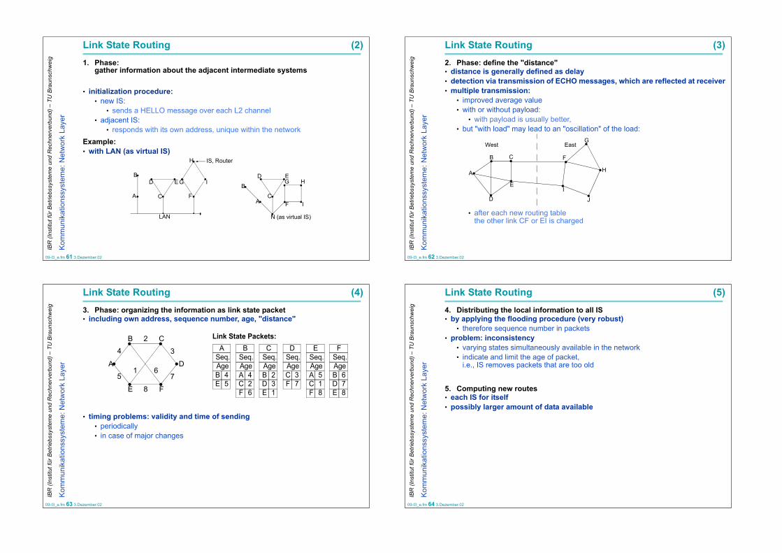
Link State Routing (2)1. Phase:
gather information about the adjacent intermediate systems
• initialization procedure:• new IS:
• sends a HELLO message over each L2 channel• adjacent IS:
• responds with its own address, unique within the networkExample:• with LAN (as virtual IS)
IS, Router
A
B
C
D E
C
D E
H
I
F
G G H
IF
N (as virtual IS)
A
B
LAN
09-l3_e.fm 62 3.Dezember.02
IBR
(Ins
titut
für B
etrie
bssy
stem
e un
d R
echn
erve
rbun
d) –
TU
Bra
unsc
hwei
g
Kom
mun
ikat
ions
syst
eme:
Net
wor
k La
yer
Link State Routing (3)2. Phase: define the "distance"• distance is generally defined as delay• detection via transmission of ECHO messages, which are reflected at receiver• multiple transmission:
• improved average value• with or without payload:
• with payload is usually better,• but "with load" may lead to an "oscillation" of the load:
• after each new routing tablethe other link CF or EI is charged
West East
B
A
D
E
C F
G
H
J
I
09-l3_e.fm 63 3.Dezember.02
IBR
(Ins
titut
für B
etrie
bssy
stem
e un
d R
echn
erve
rbun
d) –
TU
Bra
unsc
hwei
g
Kom
mun
ikat
ions
syst
eme:
Net
wor
k La
yer
Link State Routing (4)3. Phase: organizing the information as link state packet• including own address, sequence number, age, "distance"
• timing problems: validity and time of sending• periodically• in case of major changes
B C
E F
A D61
2
8
5 7
4 3 ASeq.Age
B C D E F
B 4E 5
Seq.AgeA 4C 2
Seq.AgeB 2D 3
Seq.AgeC 3F 7
Seq.AgeA 5C 1
Seq.AgeB 6D 7
F 6 E 1 F 8 E 8
Link State Packets:
09-l3_e.fm 64 3.Dezember.02
IBR
(Ins
titut
für B
etrie
bssy
stem
e un
d R
echn
erve
rbun
d) –
TU
Bra
unsc
hwei
g
Kom
mun
ikat
ions
syst
eme:
Net
wor
k La
yer
Link State Routing (5)4. Distributing the local information to all IS• by applying the flooding procedure (very robust)
• therefore sequence number in packets• problem: inconsistency
• varying states simultaneously available in the network• indicate and limit the age of packet,
i.e., IS removes packets that are too old
5. Computing new routes• each IS for itself• possibly larger amount of data available

09-l3_e.fm 65 3.Dezember.02
IBR
(Ins
titut
für B
etrie
bssy
stem
e un
d R
echn
erve
rbun
d) –
TU
Bra
unsc
hwei
g
Kom
mun
ikat
ions
syst
eme:
Net
wor
k La
yer
4.8 Multipath RoutingPrinciple:• using alternative routes between the IS pairs• usage frequency depends on the quality of the alternative• higher throughput due to the data traffic being distributed to various paths• increased reliabilityImplementation:• each IS contains a rating table including
• one row for each possible destination IS
Z ... destinationAi ... i-best outgoing line Gi ... weight for Ai
Gi determines the probability with which Ai will be used:
Z A1 G1 A2 G2 ... An Gn
Gii 1=
n
∑ 1=
09-l3_e.fm 66 3.Dezember.02
IBR
(Ins
titut
für B
etrie
bssy
stem
e un
d R
echn
erve
rbun
d) –
TU
Bra
unsc
hwei
g
Kom
mun
ikat
ions
syst
eme:
Net
wor
k La
yer
Multipath Routing (2)Example:
Selecting the alternatives: i.e., generating a random number z (0 ≤ z < 1)A1:0 ≤ z < G1A2:G1 ≤ z < G1 + G2....An:G1 + G2 + ... + Gn-1≤ z < 1
Example: destination B
dest. 1st choice
2nd choice
3rd choice
A A 0.63 I 0.21 H 0.16B A 0.46 H 0.31 I 0.23C A 0.34 I 0.33 H 0.33D H 0.50 A 0.25 I 0.25E A 0.40 I 0.40 H 0.20F A 0.34 H 0.33 I 0.33G H 0.46 A 0.31 K 0.23H H 0.63 K 0.21 A 0.16I I 0.65 A 0.22 H 0.13
K K 0.67 H 0.22 A 0.11
A B C D
HGFE
I J K L
Table from J →
0 0.46 0.77 1
A H I
09-l3_e.fm 67 3.Dezember.02
IBR
(Ins
titut
für B
etrie
bssy
stem
e un
d R
echn
erve
rbun
d) –
TU
Bra
unsc
hwei
g
Kom
mun
ikat
ions
syst
eme:
Net
wor
k La
yer
4.9 Hierarchical RoutingMotivation• a large number of IS means
• time-consuming dynamic routing calculation• storage of very large routing tables
⇒ hierarchical structure• reduces individually treated IS
Example (of 2 tables)
Comparison• but
• the best path is not always calculated• design:
• number of layers
Region 1 Region 2
Region 3 Region 5Region 4
1B1A
1C
2A2B
2C
5B 5C5A5E
5D
2D
4A4B 4C
3A3B
1B 11C 11B 21B 31B 31B 41C 31C 21C 31C 41C 41C 41C 51B 51C 61C 5
– –1A
1C2A2B2C2D3A3B4A4B4C5A5B5C5D5E
1B
Line HopsDest.
Full table for 1A
1A
1C2345
1B
Line HopsDest.Hierarchical table for 1A
1B 11C 11B 21C 21C 31C 4
– –
09-l3_e.fm 68 3.Dezember.02
IBR
(Ins
titut
für B
etrie
bssy
stem
e un
d R
echn
erve
rbun
d) –
TU
Bra
unsc
hwei
g
Kom
mun
ikat
ions
syst
eme:
Net
wor
k La
yer
4.10 Routing with MobilityPrinciple
• end system identified by its local home address• no modifications in existing IS• i.e.,
• Home-Agent: stationary address• Foreign Agent: knows mobile end system
Foreign agent
Foreign LANWAN MAN
Home LAN
Home agent
Mobile host
Wireless cell

09-l3_e.fm 69 3.Dezember.02
IBR
(Ins
titut
für B
etrie
bssy
stem
e un
d R
echn
erve
rbun
d) –
TU
Bra
unsc
hwei
g
Kom
mun
ikat
ions
syst
eme:
Net
wor
k La
yer
Routing with Mobility (2)Tunneling and Rerouting Procedures
1. Packet is sent to the mobile host’s home address
2. Packet is tunneled to the foreign agent
3. Sender is given foreign agent’s address
4. Subsequent packets are tunneled to the foreign agent
Source
ForeignAgent
HomeAgent
09-l3_e.fm 70 3.Dezember.02
IBR
(Ins
titut
für B
etrie
bssy
stem
e un
d R
echn
erve
rbun
d) –
TU
Bra
unsc
hwei
g
Kom
mun
ikat
ions
syst
eme:
Net
wor
k La
yer
5. Broadcast RoutingTerminology• Unicast: 1 : 1 communication
• Multicast: 1 : n communication• Broadcast: 1 : all communication
rec-
sender
eiver
rec-eiver
rec-eiver
Subnetwork
rec-
sender
eiver
rec-eiver
rec-eiver
rec-eiver
rec-eiver
........
.........
09-l3_e.fm 71 3.Dezember.02
IBR
(Ins
titut
für B
etrie
bssy
stem
e un
d R
echn
erve
rbun
d) –
TU
Bra
unsc
hwei
g
Kom
mun
ikat
ions
syst
eme:
Net
wor
k La
yer
5.1 Broadcast Routing: MethodsSeveral methods have been proposed for broadcasting
Simple approaches:1. Individual sending to every destination (distinct packets)• requires no special feature from the network• waste of bandwidth• sender has to know all destinations
2. Flooding• too many duplicates
09-l3_e.fm 72 3.Dezember.02
IBR
(Ins
titut
für B
etrie
bssy
stem
e un
d R
echn
erve
rbun
d) –
TU
Bra
unsc
hwei
g
Kom
mun
ikat
ions
syst
eme:
Net
wor
k La
yer
5.2 Broadcast Routing: Multidestination RoutingEach Packet CONTAINS A LIST OF DESTINATIONS
Steps performed at each IS• examine which outgoing links are required• generates a packet copy for each REQUIRED outgoing link
• packet copy contains ONLY destinations which can be reached via this line
Example:• network with I0 as the considered IS
AB
CD
H
I0I1
I2
I3
I4
I5
I1
I2
I4
I3
A
~
~
A
A
B ~
~
I0,I1,I2,I3,I4 I1,I3,I4
I2
A
B
C
Host
D
I0 routing table
in line
out linesnetwork

09-l3_e.fm 73 3.Dezember.02
IBR
(Ins
titut
für B
etrie
bssy
stem
e un
d R
echn
erve
rbun
d) –
TU
Bra
unsc
hwei
g
Kom
mun
ikat
ions
syst
eme:
Net
wor
k La
yer
5.3 Broadcast Routing: Spanning TreeIdea:• use sink tree for router initiating broadcast or other spanning tree
• subset of subnet including all routers with no loopsSpanning tree: subset of subnet including all routers with no loops
Example network, IS "I" as the sender
Prerequisite:• Spanning Tree is known to the IS
• IS generates minimum number of packet copies
• IS generates a packet copy for each required outgoing line• all spanning tree lines except incoming one
Main issue:• how to determine a Spanning Tree?
• sometimes available, e.g., from link state routing• sometimes not, e.g., with distance vector
A
EH
B C DF
JG
OM
KL N
I
Net
A B C D
GJ
O
FI
E
H
K
L
M
N
a Spanning Tree
09-l3_e.fm 74 3.Dezember.02
IBR
(Ins
titut
für B
etrie
bssy
stem
e un
d R
echn
erve
rbun
d) –
TU
Bra
unsc
hwei
g
Kom
mun
ikat
ions
syst
eme:
Net
wor
k La
yer
5.4 Broadcast Routing: Reverse Path Forwarding (RPF)Also called "Reverse Path Flooding" (RPF)• Variation of the Spanning TreePrinciple• each sender has his own Spanning Tree• but IS do not need to know the Spanning TreesConsiderations • each router has information which path it would use for (unicast)-packets
• because of the unicast routing algorithmsAlgorithm (for a packet arriving at an IS)• has this packet arrived at THE IS entry over which the packets
for this station/source are usually also sent?Yes:• packet used the BEST route until now, • action: resend over all edges (not including the incoming one)No:• action: discard packet (most likely duplicate)
09-l3_e.fm 75 3.Dezember.02
IBR
(Ins
titut
für B
etrie
bssy
stem
e un
d R
echn
erve
rbun
d) –
TU
Bra
unsc
hwei
g
Kom
mun
ikat
ions
syst
eme:
Net
wor
k La
yer
Broadcast Routing: Reverse Path Forwarding (RPF) (2)Example
Characteristics• based on the assumption of SYMMETRIC DUPLEX CHANNELS• simple implementation (no global conditions, ...)• metrics
• consist only of distanceApplication:
MBone Multicast Backbone• between MBone islands
I
F H J N
A D GKE O M O
GC D N
BH L
L B
KE
A B C D
GJ
O
FI
E
K
L
M
N
a Spanning Tree
A
EH
B C DF
JG
OM
KL N
I
Net
H
09-l3_e.fm 76 3.Dezember.02
IBR
(Ins
titut
für B
etrie
bssy
stem
e un
d R
echn
erve
rbun
d) –
TU
Bra
unsc
hwei
g
Kom
mun
ikat
ions
syst
eme:
Net
wor
k La
yer
Broadcast Routing: Reverse Path Forwarding (RPF) (3)Example:
• in the example • B will send its unicast packets to S via A (shortest route).
Broadcast Sender S
EF
X
B
A
C
D
8
2 1
2
1
3
3
23
UnicastPath

09-l3_e.fm 77 3.Dezember.02
IBR
(Ins
titut
für B
etrie
bssy
stem
e un
d R
echn
erve
rbun
d) –
TU
Bra
unsc
hwei
g
Kom
mun
ikat
ions
syst
eme:
Net
wor
k La
yer
Broadcast Routing: Reverse Path Forwarding (RPF) (4)Example:
• within the RPF algorithm of the above example• router B uses the unicast routing information to ignore all broadcast packets
received from S, WHICH DID NOT ARRIVE VIA NODE A
Broadcast Sender S
EF
X
B
A
C
D
8
2 1
2
1
3
3
23
X XX
X
X received packet may be ignored, because it did not arrive by the shortestroute
yes
no
09-l3_e.fm 78 3.Dezember.02
IBR
(Ins
titut
für B
etrie
bssy
stem
e un
d R
echn
erve
rbun
d) –
TU
Bra
unsc
hwei
g
Kom
mun
ikat
ions
syst
eme:
Net
wor
k La
yer
5.5 Broadcast Routing:Reverse Path Broadcast (RPB)Motivation: disadvantages of Reverse Path Forwarding:• when packets are forwarded,
they are forwarded over ALL edges (not including the incoming one)• better if over only one SUITABLE edge
Algorithm: packet from S(ource) to D(estination)• like REVERSE PATH FORWARDING
• with specific selection of the outgoing links• has this packet arrived via an IS entry over which packets may also be sent to
station/source S?Yes:
• packet used the BEST route until now, • THEN: select the edge at which the packets arrived and from which they are
then rerouted to source S (in reversed direction) • THEN DO NOT i.e. not as in Reverse Path Forwarding (RPF)
send over all edges (without the incoming one)No:
• discard packet (is most likely a duplicate)
09-l3_e.fm 79 3.Dezember.02
IBR
(Ins
titut
für B
etrie
bssy
stem
e un
d R
echn
erve
rbun
d) –
TU
Bra
unsc
hwei
g
Kom
mun
ikat
ions
syst
eme:
Net
wor
k La
yer
Broadcast Routing:Reverse Path Broadcast (RPB) (2)Example:
In the example• A can learn by inspecting the unicast packets
• that it is located on the unicast path from B to S• X can learn by packets failing to appear
• that it is not located on the unicast path from B to S⇒ This information is used by the RPB algorithm
Broadcast Sender S
E X
B
A
C
D
8
2 1
2
1
3
3
23
UnicastPath
09-l3_e.fm 80 3.Dezember.02
IBR
(Ins
titut
für B
etrie
bssy
stem
e un
d R
echn
erve
rbun
d) –
TU
Bra
unsc
hwei
g
Kom
mun
ikat
ions
syst
eme:
Net
wor
k La
yer
Broadcast Routing:Reverse Path Broadcast (RPB) (3)Example:
In the example with the RPB algorithm• X does not forward a broadcast packet from S to B, because X knows
• that B does not receive unicast packets via X• but sends them over a different node instead with• this other node then receiving the broadcast packet
⇒ Connection X-B relieved in comparison to the RPF algorithm
Broadcast Sender S
E X
B
A
C
D
8
2 1
2
1
3
3
23
XX
X
XX no transmission of broadcast
packets into this direction, becausethe opposing party does not sendpackets to S over this channel.

09-l3_e.fm 81 3.Dezember.02
IBR
(Ins
titut
für B
etrie
bssy
stem
e un
d R
echn
erve
rbun
d) –
TU
Bra
unsc
hwei
g
Kom
mun
ikat
ions
syst
eme:
Net
wor
k La
yer
Broadcast Routing:Reverse Path Broadcast (RPB) (4)Comment:• when distance is the same:
• IS with the shortest address is selected• IS utilize the routing information,
• to exploit this parent-child relationship(BELOW ANOTHER EXPLANATION)Principle• as in REVERSE PATH FORWARDING
i.e., only packets which arrived over the "best" path are forwarded, but... • collision avoidance
(additional discarding of packets)by defining a PARENT-CHILD RELATIONSHIP
• provided that knowledge of the Spanning Tree exists• or parent-child relationship:
• IS B is the parent of the adjacent IS X, IF its distance to source Zis shorter than the distances of all other neighbours of X
• (in the example: B is parent of X)
Z (resp. Source)
A B C
X
6 3 5
09-l3_e.fm 82 3.Dezember.02
IBR
(Ins
titut
für B
etrie
bssy
stem
e un
d R
echn
erve
rbun
d) –
TU
Bra
unsc
hwei
g
Kom
mun
ikat
ions
syst
eme:
Net
wor
k La
yer
Broadcast Routing:Reverse Path Broadcast (RPB) (5)Algorithm for selecting the outgoing links• X is the PARENT of a link,
• IF its distance to the source is shorter than Y’s distance (or than all other ones)• if distance is the same:
• decision is based on the shorter address• router exchange routing informationen with each other to determine parent-
child relationship
Example• link a is the child of X,
not of Y• PACKETS FORWARDED ONLY OVER CHILD LINKS
(this results in the Spanning Tree)
S
X Y
Z
5 6
Link a
09-l3_e.fm 83 3.Dezember.02
IBR
(Ins
titut
für B
etrie
bssy
stem
e un
d R
echn
erve
rbun
d) –
TU
Bra
unsc
hwei
g
Kom
mun
ikat
ions
syst
eme:
Net
wor
k La
yer
6. Multicast RoutingMulticast Definition• Unicast: 1:1 communication• Multicast: 1:n communicationTasks• to send data to a group of end systems
• one-time sending instead of• multiple sending
• to maintain the overall load at a low levelResults• lower network load• lower load on the senderCondition: group addressing• group membership may change, managed for example by:
• Internet Group Management Protocol (IGMP)• group management (create, destroy, join, leave)
• somehow related protocols for session maintenance• Session Description Protocol (SDP)• Session Announcement Protocol (SAP)• Session Initiation Protocol (SIP)
Receiver
Sender
Sender
Receiver
Not a Rec.
Receiver
Receiver
Receiver
09-l3_e.fm 84 3.Dezember.02
IBR
(Ins
titut
für B
etrie
bssy
stem
e un
d R
echn
erve
rbun
d) –
TU
Bra
unsc
hwei
g
Kom
mun
ikat
ions
syst
eme:
Net
wor
k La
yer
6.1 Multicast Routing: Spanning Tree
Principle• global knowledge of the multicast group’s spannig tree (Multicast Tree), • initially only local knowledgeDistribution of Information• first IS adapts spanning tree to the specific group
i.e. aligning (propagating) the spanning tree by• distance vector routing or link state routing
1, 2
1
1, 22 1
2
1
21, 2
2
1, 2
2 21
1
1 1
1 1
1
22
2
2 2
who
le s
ubne
t
span
ning
tree
mul
ticas
t tre
e
1multicast source IS
for g
roup
1
mul
ticas
t tre
efo
r gro
up 2
for l
eftm
ost I
S

09-l3_e.fm 85 3.Dezember.02
IBR
(Ins
titut
für B
etrie
bssy
stem
e un
d R
echn
erve
rbun
d) –
TU
Bra
unsc
hwei
g
Kom
mun
ikat
ions
syst
eme:
Net
wor
k La
yer
Multicast Routing: Spanning Tree with Link State RoutingPrinciple: all IS must know the multicast tree• i.e. each IS
• KNOWS TO WHICH GROUP IT BELONGS• but DOES NOT know (initially) which other IS belong to the group as well
• distribution of this information• depends on the underlying routing protocol• here: Link State Routing
Link State Routing• all IS send link state packets periodically
• containing information• distance to neighbours• EXPANDED by information on multicast groups
• by broadcast to all the others• each IS calculates a multicast tree
• from the now locally available and complete state information• based on the information about the multicast tree
• IS determines the outgoing lines• on which packets have to be transmitted
09-l3_e.fm 86 3.Dezember.02
IBR
(Ins
titut
für B
etrie
bssy
stem
e un
d R
echn
erve
rbun
d) –
TU
Bra
unsc
hwei
g
Kom
mun
ikat
ions
syst
eme:
Net
wor
k La
yer
Multicast Routing: Spanning Tree with Distance Vector R.Principle: all IS have to know the multicast tree• i.e. each IS
• KNOWS WHICH GROUP IT BELONGS TO• but DOES NOT know (inititally) which other IS also belong to the group
• distribution of this information • depends on the underlying routing protocol• here: Distance Vector Multicast Routing Protocol DVMRP
Method: REVERSE PATH FORWARDING WITH PRUNING• (Pruning: feedback in order to stop data transfer)
09-l3_e.fm 87 3.Dezember.02
IBR
(Ins
titut
für B
etrie
bssy
stem
e un
d R
echn
erve
rbun
d) –
TU
Bra
unsc
hwei
g
Kom
mun
ikat
ions
syst
eme:
Net
wor
k La
yer
Multicast Routing: Spanning Tree with Distance Vector R.(2)Principle• sender sends first multicast packet to everybody,
using the broadcast method Reverse Path Forwarding RPF• then apply adaptation (PRUNING)
• because broadcasting too resource consuming• from broadcast communication to the multicast structure• originating from the leaves of the spanning tree:
• if multicast packet arrives from IS leaf NOT belonging to multicast group:• send a NON-MEMBERSHIP-REPORT (NMR) to the immediate predecessor• propagate a Non-Membership-Report NMR, if
1. IS receives Non-Membership-Reports NMRs from all descendents2. but does not belong to the group itself
• if multicast packet arrives from IS leaf which DOES BELONG TO multicast group:• nothing happens on the IS side
(i.e., the following multicast packets are also send there again)Benefit:• pruning only on trees that are actually used
• unused trees are cut coarsely• optimized for many receivers
09-l3_e.fm 88 3.Dezember.02
IBR
(Ins
titut
für B
etrie
bssy
stem
e un
d R
echn
erve
rbun
d) –
TU
Bra
unsc
hwei
g
Kom
mun
ikat
ions
syst
eme:
Net
wor
k La
yer
6.2 Multicast Routing: Core-Based Tree
• also know as "Trees with Rendezvous Points"
Principle• the CORE is selected (an IS which is central to the group)• the group’s spanning tree from this node/IS is determined• the sender transmits a packet to this central IS• the core transmits this packet via the spanning treeProperties
+ simple central calculation+ one tree common to all n senders (instead of n trees)- route to the central IS may not be optimized
Core IS (Router)
Non-Core-IS (Router)1.
2.

09-l3_e.fm 89 3.Dezember.02
IBR
(Ins
titut
für B
etrie
bssy
stem
e un
d R
echn
erve
rbun
d) –
TU
Bra
unsc
hwei
g
Kom
mun
ikat
ions
syst
eme:
Net
wor
k La
yer
6.3 Multicast Routing: Additional Procedures & TopicsVariants (some additional ones)• Truncated Reverse Path Forwarding (TRPB)
• enhancement of broadcast procedure "Reverse-Path-Broadcast"• Steiner Trees (optimizing network resources)• Reverse Path Multicast (RPM)• Distance Vector Multicast Routing Protocol (DVMRP)
first version of DVMRP (RFC 1075) based on RPM• hierarchical DVMRP
• two-tiered, non-overlapping domains/subnetworks• Multicast Open Shortest Path First (MOSPF)
• based on link state routing OSPF• Protocol Independent Multicast (PIM)
• for groups with small spatial density
09-l3_e.fm 90 3.Dezember.02
IBR
(Ins
titut
für B
etrie
bssy
stem
e un
d R
echn
erve
rbun
d) –
TU
Bra
unsc
hwei
g
Kom
mun
ikat
ions
syst
eme:
Net
wor
k La
yer
Multicast Routing: Additional Procedures & Topics (2)
Objectives: optimizations / constraints • edge optimization: e.g., path with largest bandwidth• edge limited: e.g., find a path that adheres to the constraints at
every edge• path optimization: e.g., path with the lowest overall costs• path limited: e.g., path which does not exceed certain overall delay
Reserving resources• Resource Reservation Protocol (RSVP)• Stream Protocol Version 2 (ST-2)
Quality of Service• negotiation• with heterogenous receivers (filtering)• adaptation (scaling)
09-l3_e.fm 91 3.Dezember.02
IBR
(Ins
titut
für B
etrie
bssy
stem
e un
d R
echn
erve
rbun
d) –
TU
Bra
unsc
hwei
g
Kom
mun
ikat
ions
syst
eme:
Net
wor
k La
yer
7. Congestion ControlWhen too much traffic is offered:• congestion sets in• performance degrades sharplyReasons for congestion, among others• IS too slow for routing algorithms• incoming traffic overloads outgoing lines
Congestions tend to amplify themselvesExample: IS drops packet due to congestion• packet has to be retransmitted
• additional bandwidth used• sender cannot release the buffer
• thereby additionally tying up resources
congestion control vs. flow controlmanaged by subnet (L3) concatenated point-to-point (L2)
global issue more an end-to-end issueif possible, avoid from the beginning reduce effects
may use flow control
congested
desirable
perfectmaximum transmissioncapacity of the subnet
packets sent
pac
kets
del
iver
ed
09-l3_e.fm 92 3.Dezember.02
IBR
(Ins
titut
für B
etrie
bssy
stem
e un
d R
echn
erve
rbun
d) –
TU
Bra
unsc
hwei
g
Kom
mun
ikat
ions
syst
eme:
Net
wor
k La
yer
Congestion Control (2)General methods of resolution• increase capacity• decrease traffic
Taxonomy according to Yang/Reedy 1995• open loop: avoid (before congestion happens)
• initiate countermeasures at the sender• initiate countermeasures at the receiver
• closed loop: repair• explicit feedback (packets are sent from the point of congestion)• implicit feedback (source assumes that congestion occured due to other effects)
Strategies1. avoidance
• traffic shaping, leaky bucket, token bucket, reservation (multicast), isarithmic congestion control
• flow control (not discussed herein) 2. repair
• drop packets, choke packets, hop-by-hop choke packets, fair queuing,...

09-l3_e.fm 93 3.Dezember.02
IBR
(Ins
titut
für B
etrie
bssy
stem
e un
d R
echn
erve
rbun
d) –
TU
Bra
unsc
hwei
g
Kom
mun
ikat
ions
syst
eme:
Net
wor
k La
yer
7.1 Congestion AvoidancePrinciple• appropriate communication system behavior and designPolicies at various layers can affect congestion
Data link layer• flow control• acknowledgements• error treatment / retransmission / FEC
Network layer• datagram (more complex) vs. virtual circuit (more procedures available)• packet queueing and scheduling in IS• packet dropping in IS (including packet lifetime)• selected route
Transport layer• basically the same as for the data link layer• but some issues are harder (determining timeout interval)
09-l3_e.fm 94 3.Dezember.02
IBR
(Ins
titut
für B
etrie
bssy
stem
e un
d R
echn
erve
rbun
d) –
TU
Bra
unsc
hwei
g
Kom
mun
ikat
ions
syst
eme:
Net
wor
k La
yer
Avoidance by Traffic Shaping
Motivation• congestion is often caused by bursts• bursts are relieved by smoothening the traffic (at the cost of a delay)Procedure• negotiate the traffic contract beforehand (e.g., flow specification)• the traffic is shaped by the end device
• average rate and• burstiness
Application: virtual circuits in ATM• ”traffic shaper” smoothens extremely fluctuating traffic• trade-off: loss of cells vs. delay
r(t)
tAverage Rate
Peak Cell RatePeak Input
original source
smoothened stream
09-l3_e.fm 95 3.Dezember.02
IBR
(Ins
titut
für B
etrie
bssy
stem
e un
d R
echn
erve
rbun
d) –
TU
Bra
unsc
hwei
g
Kom
mun
ikat
ions
syst
eme:
Net
wor
k La
yer
Traffic Shaping with Leaky BucketPrinciple• continuous outflow• congestion corresponds to
data loss• 1986: Turner
Implementation• easy if packet length stays constant (like ATM cells) • example
Buffer(Permit)
Pool
R
arrivals output
Rate
B
inflow
continuousoutflow
LeakyBucket
Time (msec)0 500
0 500Time (msec)
25 MB/sec for 40 msec
2 MB/sec for 500 msec
09-l3_e.fm 96 3.Dezember.02
IBR
(Ins
titut
für B
etrie
bssy
stem
e un
d R
echn
erve
rbun
d) –
TU
Bra
unsc
hwei
g
Kom
mun
ikat
ions
syst
eme:
Net
wor
k La
yer
Traffic Shaping with Token BucketPrinciple• permit a certain amount of data to flow off for a certain amount of time• controlled by "tokens"• number of tokens limited
Implementation• add tokens periodically
(until maximum has been reached)• remove token: depending on the length of
the packet (byte counter)
Comparison• Leaky Bucket
• max. constant rate (at any point in time)• Token Bucket:
• permits a limited burst Network
Host computer
The bucket holds tokens
Network
One token is added
to the bucket every ∆T
before after
Host computer

09-l3_e.fm 97 3.Dezember.02
IBR
(Ins
titut
für B
etrie
bssy
stem
e un
d R
echn
erve
rbun
d) –
TU
Bra
unsc
hwei
g
Kom
mun
ikat
ions
syst
eme:
Net
wor
k La
yer
Avoidance by Reservation: Admission ControlPrinciple:• prerequisite: virtual circuits• reserving the necessary resources (incl. buffers) during connect• if buffer or other resources not available
• alternative path• desired connection refused
Example:• network layer may adjust routing based on congestion• when the actual connect occurs
A
CongestionVirtual circuit
Congestion
B
A
B
09-l3_e.fm 98 3.Dezember.02
IBR
(Ins
titut
für B
etrie
bssy
stem
e un
d R
echn
erve
rbun
d) –
TU
Bra
unsc
hwei
g
Kom
mun
ikat
ions
syst
eme:
Net
wor
k La
yer
Avoidance by Buffer Reservation
Principle:• buffer reservationImplementation variant: Stop-and-Wait protocol• one buffer per IS and connection (simplex, VC=virtual circuit)Implementation variant: Sliding Window protocol• m buffer per IS and (simplex-) connection (m corresp. to the window size)Properties:• congestion not possible• buffers remain reserved,
even if there is no data transmission for some periods• therefore, usually only for applications that require low delay and high
bandwidth (e.g., digital voice transmission)
VC1
VC2
ISIS IS
09-l3_e.fm 99 3.Dezember.02
IBR
(Ins
titut
für B
etrie
bssy
stem
e un
d R
echn
erve
rbun
d) –
TU
Bra
unsc
hwei
g
Kom
mun
ikat
ions
syst
eme:
Net
wor
k La
yer
Avoidance by Reservation: Multicast and Time GuaranteesReservation protocols• Resource Reservation Protocol (RSVP)• Stream Type Protocol Version 2 (ST-2)Searching for the most ideal IS to connect to an MC groupExample
A
D
G
J
C
FBandwidth reserved for source 1
Bandwidth reserved for source 2
I
L
B
K
H
E
1 2
3 4 5
A
D
G
J
C
F
I
L
B
K
H
E
1 2 2
3 4 5
A
D
G
J
C
F
I
L
B
K
H
E
new destination
3 4 5
1
09-l3_e.fm 100 3.Dezember.02
IBR
(Ins
titut
für B
etrie
bssy
stem
e un
d R
echn
erve
rbun
d) –
TU
Bra
unsc
hwei
g
Kom
mun
ikat
ions
syst
eme:
Net
wor
k La
yer
Avoidance by Isarithmic Congestion Control
Principle• limiting the number of packets in the network by assigning "permits"
• amount of "permits" in the network• a "permit" is required for sending
• when sending: "permit" is destroyed• when receiving: "permit" is generated
Problems• parts of the network may be overloaded• equal distribution of the "permits" is difficult• additional bandwidth for the transfer of "permits" necessary• bad for transmitting large data amounts (e.g. file transfer)• loss of "permits" hard to detect

09-l3_e.fm 101 3.Dezember.02
IBR
(Ins
titut
für B
etrie
bssy
stem
e un
d R
echn
erve
rbun
d) –
TU
Bra
unsc
hwei
g
Kom
mun
ikat
ions
syst
eme:
Net
wor
k La
yer
7.2 Congestion Correction
Principle• no resource reservation• necessary steps
• detect congestion• introduce appropriate procedures for reduction
09-l3_e.fm 102 3.Dezember.02
IBR
(Ins
titut
für B
etrie
bssy
stem
e un
d R
echn
erve
rbun
d) –
TU
Bra
unsc
hwei
g
Kom
mun
ikat
ions
syst
eme:
Net
wor
k La
yer
Packet droppingPrinciple:• incoming packet is dropped, if it cannot be buffered
Preconditions for• datagram:
• no preparations necessary• connection-oriented service:
• packet will be buffered until receipt has been acknowledged
Buffer assignment methods1. Permanent buffers per incoming line• ACK
• would have to be discarded• during overwrite, ACK would release buffer• (comment: in the above picture the ACK refers to the 5 buffer slots on the right)
IS
X XXXXACK
09-l3_e.fm 103 3.Dezember.02
IBR
(Ins
titut
für B
etrie
bssy
stem
e un
d R
echn
erve
rbun
d) –
TU
Bra
unsc
hwei
g
Kom
mun
ikat
ions
syst
eme:
Net
wor
k La
yer
Packet dropping (2)2. Maximum number of buffers per output line• example:
• packet dropped despite there are free lines• heuristic rule [Irland]
m ... max. number of buffers per output linek ... total number of bufferss ... number of output lines
3. Minimal number of buffers per output line• line cannot be starved
Example ARPANET• a combination of 2) and 3)
inputlines
output lines avail. buffers
m ks-------=
09-l3_e.fm 104 3.Dezember.02
IBR
(Ins
titut
für B
etrie
bssy
stem
e un
d R
echn
erve
rbun
d) –
TU
Bra
unsc
hwei
g
Kom
mun
ikat
ions
syst
eme:
Net
wor
k La
yer
Packet dropping (3)4. Content-related dropping: relevance• reference
• data connection as a whole(or all single data packets from one end system to another end system)
• single packets,examples
• WWW documentimages vs. text and structural information
• file transfer:old packets more important than new ones(algorithm to initiate correction process should start as late as possible)
• implementation of priorities• in virtual circuits or datagrams• example: ATM

09-l3_e.fm 105 3.Dezember.02
IBR
(Ins
titut
für B
etrie
bssy
stem
e un
d R
echn
erve
rbun
d) –
TU
Bra
unsc
hwei
g
Kom
mun
ikat
ions
syst
eme:
Net
wor
k La
yer
Packet dropping (4)Properties:• very simplebut• retransmitted packets waste bandwidth:• packet has to be sent 1 / (1 - p) times before it is accepted
• (p ... probability that packet will be dropped)
Optimization necessary to reduce the wastage of bandwidth• dropping packets that have not gotten that far yet
09-l3_e.fm 106 3.Dezember.02
IBR
(Ins
titut
für B
etrie
bssy
stem
e un
d R
echn
erve
rbun
d) –
TU
Bra
unsc
hwei
g
Kom
mun
ikat
ions
syst
eme:
Net
wor
k La
yer
Choke PacketsPrinciple: • reduce traffic during congestion by telling source to slow downProcedure for IS: each outgoing line (OL) has one variable = utilization• calculating u ( 0 ≤ u ≤ 1 ) (u: UTILIZATION)
• IS checks the line usage f periodically ( = 0 or 1)• u = a * u + ( 1 - a ) * f• 0 ≤ a ≤ 1 determines to what extent "history" is taken into account
• u > threshold: OL changes to condition "warning"• send CHOKE PACKET to source (indicating destination)• tag packet (to avoid further choke packets from down stream IS) and forward it
Procedure for source• source receives the choke packet
• reduces the data traffic to the destination in question by X1%• source recognizes 2 phases:
(gate time so that the algorithm can take effect)• Ignore: ES ignores further Choke packets• Listen: ES listens if more Choke packets are arriving
• yes: further reduction by X2%;go to Ignore phase
• no: increase the data traffic
Ignore Listen
09-l3_e.fm 107 3.Dezember.02
IBR
(Ins
titut
für B
etrie
bssy
stem
e un
d R
echn
erve
rbun
d) –
TU
Bra
unsc
hwei
g
Kom
mun
ikat
ions
syst
eme:
Net
wor
k La
yer
Choke Packets (2)Enhancements• varying choke packets depending on state of congestion
• warning• acute warning
• for u instead of utilization• queue length• ....
Properties• effective procedure• but
• possibly many choke packets in the network• even if Choke bits may be included in the data at the senders
to minimize reflux• end systems can (but do not have to) adjust the traffic• superimposed by mechanisms
• L2 flow control, ...• L4 TCP, ..
09-l3_e.fm 108 3.Dezember.02
IBR
(Ins
titut
für B
etrie
bssy
stem
e un
d R
echn
erve
rbun
d) –
TU
Bra
unsc
hwei
g
Kom
mun
ikat
ions
syst
eme:
Net
wor
k La
yer
Choke Packets: Hop-by-Hop Choke Packets (3)Principle• reaction to Choke packets already at IS (not only at ES)Example
(pla
in) C
hoke
-Pac
kets
B C
A D
E F
Reduced flow
Flow is still at maximum rate
Flow is reduced
B C
A D
E F Heavy flow
Hop
-By-
Hop
Cho
ke P
acke
ts
ChokeChoke Reduced
flow

09-l3_e.fm 109 3.Dezember.02
IBR
(Ins
titut
für B
etrie
bssy
stem
e un
d R
echn
erve
rbun
d) –
TU
Bra
unsc
hwei
g
Kom
mun
ikat
ions
syst
eme:
Net
wor
k La
yer
Random Early Detection (RED)
Idea:• Congestion should be attacked as early as possible• some transport protocols (e.g., TCP) react to lost packets by rate reductionIS drops some packet before congestion significant (i.e., early)• gives time to reactDropping starts when moving avg. of queue length exceeds threshold• small bursts pass through unharmed• only affects sustained overloads• Packet drop probability is a function of mean queue length
• prevents severe reaction to mild overloadCan mark packets instead of dropping them• allows sources to detect network state without losses
RED improves performance of a network of cooperating TCP sources
No bias against bursty sources
Controls queue length regardless of endpoint cooperation
09-l3_e.fm 110 3.Dezember.02
IBR
(Ins
titut
für B
etrie
bssy
stem
e un
d R
echn
erve
rbun
d) –
TU
Bra
unsc
hwei
g
Kom
mun
ikat
ions
syst
eme:
Net
wor
k La
yer
8. Addressing3 types of identifiers: names, addresses and routes [Shoch 78]
"The NAME of a resource indicates WHAT we seek,an ADDRESS indicates WHERE it is, anda ROUTE says HOW TO GET THERE."
Objectives:• global addressing concept for ES• simplified address allocation• addresses independent from
• type and topology of the subnetworks• number and type of the subnetworks to which the ES have been connected• location of a source ES
09-l3_e.fm 111 3.Dezember.02
IBR
(Ins
titut
für B
etrie
bssy
stem
e un
d R
echn
erve
rbun
d) –
TU
Bra
unsc
hwei
g
Kom
mun
ikat
ions
syst
eme:
Net
wor
k La
yer
8.1 X.121 AddressingCCITT/ITU "numbering scheme"• addressing concept for public data networks• a.o., used by X.25X.121 address:
• a maximum of 14 digits• consisting of
• Data Network Identification Code (4 digits)• Data Country Code (digits 1 - 3)• Network Identification (digit 4)
• Network Terminal Number (max. 10 digits)Example:
DCC for USA: 310 - 329, i. e. max. 200 networksDCC for Tonga: 539, i. e. max. 10 networks
DCC Network IDNTN
1 2 3 4 14
09-l3_e.fm 112 3.Dezember.02
IBR
(Ins
titut
für B
etrie
bssy
stem
e un
d R
echn
erve
rbun
d) –
TU
Bra
unsc
hwei
g
Kom
mun
ikat
ions
syst
eme:
Net
wor
k La
yer
8.2 OSI AddressingObjective:• global addressing concept for both existing and new subnetworksSituation: different concepts exist for• public networks:
• X.121: data networks• F.69: telex• E.163: telephone network • E.164: ISDN, ...
• private networks⇒ i.e., a flexible and expandable concept is necessary
OSI method: unique NSAP identificationOSI method: hierarchic addresses• OSI defines the ADDRESSING DOMAINS• the domain contains the ADDRESSING AUTHORITY• Addressing Authority
• allocates addresses• creates new domains and delegates authority

09-l3_e.fm 113 3.Dezember.02
IBR
(Ins
titut
für B
etrie
bssy
stem
e un
d R
echn
erve
rbun
d) –
TU
Bra
unsc
hwei
g
Kom
mun
ikat
ions
syst
eme:
Net
wor
k La
yer
OSI Addressing (2)graphic representation of the domain hierarchy:
A domain may be• networks of one type• networks of a geographical region• networks of an organisation• ...
W X
Y
ZF G
A
BC DE
Domainor
Domain
W X Y Z
A
B C D
E F G
09-l3_e.fm 114 3.Dezember.02
IBR
(Ins
titut
für B
etrie
bssy
stem
e un
d R
echn
erve
rbun
d) –
TU
Bra
unsc
hwei
g
Kom
mun
ikat
ions
syst
eme:
Net
wor
k La
yer
OSI Addressing: Structure (3)Address length: 20 bytes (binary) or 40 digitsAddress structure:• Initial Domain Part (IDP) with
• AUTHORITY AND FORMAT IDENTIFIER (AFI)• specifies how to interpret the IDI
(syntax and semantics)• e.g. the format of the DSP (binary or digits)
• INITIAL DOMAIN PART (IDI)• identifies the Addressing Authority (AA),
responsible for ALLOCATING THE NSAP ADDRESSES• identifies the domain
• Domain Specific Part (DSP)• contains the address clearly identifying the ES within the domain
IDP DSP
IDI FormatDSP SYNTAX
Decimal Binary
Character NationalCharacter
50 51
X.121ISO DCCF.69
363840
373941
09-l3_e.fm 115 3.Dezember.02
IBR
(Ins
titut
für B
etrie
bssy
stem
e un
d R
echn
erve
rbun
d) –
TU
Bra
unsc
hwei
g
Kom
mun
ikat
ions
syst
eme:
Net
wor
k La
yer
8.3 Internet Addresses (IP)Global addressing concept for ES (and IS) in the Internet• 32 bit address (amount is limited!)• each address is unique worldwide• structure: Net-ID (Subnet-ID), ES-ID
1
1 111 1 11 1
0
0
0
0
1 1 1 11 1 1
7 24Network Host
14 16Network Host
21 8HostNetwork
28Multicast address
overall 4 byte (32 bit)
11 1 1 11 1 1
28reserved for future use0
1
09-l3_e.fm 116 3.Dezember.02
IBR
(Ins
titut
für B
etrie
bssy
stem
e un
d R
echn
erve
rbun
d) –
TU
Bra
unsc
hwei
g
Kom
mun
ikat
ions
syst
eme:
Net
wor
k La
yer
Internet Addresses (IP) (2)Notation• decimal value for each byte (0...255)• subdivided by dots• value range: 0.0.0.0 ... 255.255.255.255
Formats: 5 classesA: 1.0.0.0 up to 127.255.255.255B: 128.0.0.0 up to 191.255.255.255C: 192.0.0.0 up to 223.255.255.255D: 224.0.0.0 up to 239.255.255.255 (Multicast)E: 240.0.0.0 up to 247.255.255.255Broadcast addresses: (convention: 11...1 for Host-ID)

09-l3_e.fm 117 3.Dezember.02
IBR
(Ins
titut
für B
etrie
bssy
stem
e un
d R
echn
erve
rbun
d) –
TU
Bra
unsc
hwei
g
Kom
mun
ikat
ions
syst
eme:
Net
wor
k La
yer
Internet Addresses (IP) (3)Address allocation• class allocation and network range:
• by a central authority• Network Information Center NIC
• end system• local• possibly forming a subnetwork
Example• network
F2F1 F3
E1
1 2 3 4
E2 E3 E4 E5 E6
192.31.65.7192.31.65.5
To W
AN
Router has 2 IP addresses
192.31.60.4192.31.65.1
Router has 2 IP addresses192.31.60.7192.31.63.3
192.31.63.8
Ethernet addresses
Campus network
192.31.60.0CS Ethernet 192.31.65.0
EE Ethernet 192.31.63.0
09-l3_e.fm 118 3.Dezember.02
IBR
(Ins
titut
für B
etrie
bssy
stem
e un
d R
echn
erve
rbun
d) –
TU
Bra
unsc
hwei
g
Kom
mun
ikat
ions
syst
eme:
Net
wor
k La
yer
Internet Addresses (IP): A Critical Review (4)
Addresses IDENTIFIY "NETWORK CONNECTIONS", not the ES• "multi-homed" ES have more than one address• a change of the connection forces the modification of the address• the address has an impact on the chosen route
(constitutes a problem in the mobile area)Example: A cannot reach B via address I5 if G fails• comment: is also valid for X.121
Amount of addresses• limited
G A B
I1
I2
I3 I4
I5
Network 1
Network 2
09-l3_e.fm 119 3.Dezember.02
IBR
(Ins
titut
für B
etrie
bssy
stem
e un
d R
echn
erve
rbun
d) –
TU
Bra
unsc
hwei
g
Kom
mun
ikat
ions
syst
eme:
Net
wor
k La
yer
Internet Addresses (IP): The Future (5)IP Version 6 (IPv6)• 16 byte length (instead of 4 byte length, i.e. approx. 3 x 1038)
Distribution• provider-based: approx. 16 mio. companies distribute addresses• geographic-based: distribution as it is today• link, site-used: address relevant only locally (security, Firewall concept)
e.g. new: Anycast• sending data to an individual of a group• e.g. the one who is geograhically the closest
09-l3_e.fm 120 3.Dezember.02
IBR
(Ins
titut
für B
etrie
bssy
stem
e un
d R
echn
erve
rbun
d) –
TU
Bra
unsc
hwei
g
Kom
mun
ikat
ions
syst
eme:
Net
wor
k La
yer
Internet Addresses (IP): The Future (6)
Prefix (binary) Usage Fraction0000 0000 Reserved (including IPv4) 1/2560000 0001 Unassigned 1/2560000 001 OSI NSAP addresses 1/1280000 010 Novell Netware IPX addresses 1/1280000 011 Unassigned 1/1280000 1 Unassigned 1/320001 Unassigned 1/16001 Unassigned 1/8010 Provider-based addresses 1/8011 Unassigned 1/8100 Geographic-based addresses 1/8101 Unassigned 1/8110 Unassigned 1/81110 Unassigned 1/16
1111 0 Unassigned 1/321111 10 Unassigned 1/641111 110 Unassigned 1/128
1111 11100 Unassigned 1/5121111 111010 Link local use addresses 1/10241111 111011 Site local use addresses 1/10241111 1111 Multicast 1/256