Embed Size (px)
Citation preview

Copyright © 2017 Pahlén AB, Box 728, SE-194 27 Upplands Väsby, SwedenTel. +46 8 594 110 50, Fax +46 8 590 868 80, e-mail: [email protected], www.pahlen.com
CompactManualUser manualGebrauchsanleitungИнструкцияManualManualeManual
MA
45-1
9 re
v.1
Swedish design and manufacture
since 1967
سخان كهربائي صغير الحجم
MA
45-1
9A
العربية
الدليل
سخان كهربائي صغير الحجم
MA
45-1
9A
العربية
الدليل

سخان كهربائي صغير الحجم
MA
45-1
9A
العربية
الدليل
SVENSKA 3
ENGLISH 5
DEUTSCH 7
РУССКИЙ 9
ESPAÑOL 11
ITALIANO 13
POLSKI 15
17

3
Elvärmare Aqua KompaktM
A45
-19S
SVENSKA
Art.no.
Rev.no.
Scale
Designed by: Approved by:
Revised by: Date
Drawn by: Date
Drawing number
Assembly drawing no.
Surface treatment
part of ISO 2768-1 The tolerance class in accordance with this
E
Box 728, SE-194 27 Upplands Väsby, SwedenPhone +46 8 59411050, Fax +46 8 59086880
TS
TS 2007-12-12
Medium
Elvärmare kompakt 3-18kW
M10930 0
This
doc
umen
t and
its
cont
ents
are
the
excl
usiv
e pr
oper
ty o
f Pah
léns
and
may
not
be
copi
ed,
repr
oduc
e d, t
rans
mitt
ed o
r com
mun
icat
ed to
a th
ird
party
, or u
sed
for a
ny p
urpo
se w
ithou
t writ
ten
perm
issi
on.
148
97,4
206
173
1½”
1½”
Art.no.
Rev.no.
Scale
Designed by: Approved by:
Revised by: Date
Drawn by: Date
Drawing number
Assembly drawing no.
Surface treatment
part of ISO 2768-1 The tolerance class in accordance with this
E
Box 728, SE-194 27 Upplands Väsby, SwedenPhone +46 8 59411050, Fax +46 8 59086880
1399000OA 2008-09-02
ASA 2009-03-26
Elvärmare kompaktFästkit inre
jordning M10932 1
M10718139900XPlasticTerminal box1ADIN 7980 - 419941016A2Bricka FBB18M1086419940304SteelFyrkantsbricka17M1081814564220SteelJordbleck16ISO 4032 - M419930015A4Mutter M6M M4 25plast jord19950100PlasticDistansrör, vit plast14DIN 7985 (H) - M4x12-H19909221A2Skruv MRX M4x1213M10952147020PlasticFästring12O-ring 62x219970622NBR70O-ring 62x2 NBR7011
Drawing.no:Art.noMaterialTitle/ NameQty.Item.
This
doc
umen
t and
its
cont
ents
are
the
excl
usiv
e pr
oper
ty o
f Pah
léns
and
may
not
be
copi
ed,
repr
oduc
e d, t
rans
mitt
ed o
r com
mun
icat
ed to
a th
ird
party
, or u
sed
for a
ny p
urpo
se w
ithou
t writ
ten
perm
issi
on.
1
23
45
67
8
Jordkabel
5
A
>4
00
>5
00
80
0
1
4
2
3
55
7
6
8
9
10
1/8” - Pressostat monteras här
Bild 1
½” - Flödesvakt monteras här
1. Bräddavlopp 2. Bottenavlopp 3. Inlopp 4. JetSwim 5. Belysning 6. Pump 7. Filter 8. Elvärmare 9. Backventil 10. Avlopp
A. Kopplingsbox
1399000 Fästkit inre:1. O-ring2. Fästring3. Skruv4. Distansrör5. Mutter6. Jordbleck7. Fyrkantsbricka8. Bricka
Bild 2
Jordkabel
ProduktbeskrivningElvärmare Kompakt finns från 3kW till 18kW, se typskylt på produkten. Av säkerhetsskäl skall elvärmaren förses med flödesvakt eller pressostat. I boxen kan termostat och/eller överhettningsskydd monteras. Elvärmare Kompakt är i standardutförande ej avsedd att användas i aggressivt vatten, saltvatten eller i pooler med klormaskin/saltgenerator. I sådana sammanhang krävs Elvärmare Kompakt Titan.
Produkten är avsedd för följande vattenvärden: (Utanför dessa värden gäller ej produktgarantin.) Elv Kompakt Standard Elv Kompakt Titan Klorhalt: max 3 mg/l (ppm) max 3 mg/l (ppm) Klorid(salt)halt: max 250 mg/l — pH-värde: 7.2–7.6 7.2–7.6 Alkalinitet: 60–120 mg/l (ppm) 60–120 mg/l (ppm) Kalciumhårdhet: 100–300 mg/l (ppm) 100–300 mg/l (ppm)
Tekniska data Elv Kompakt med flödesvakt Elv Kompakt med pressostat Elv Kompakt utan flödesvakt/pressostat
Max temperatur: 60°C 60°C 60°CMax tryck: 2,5 bar 4 bar 10 barMin flöde 3–9kW: 85 l/min 20 l/min 20 l/min Min flöde 12–18kW: 85 l/min 40 l/min 40 l/min
SäkerhetOm värmaren placeras mot brännbart material, skall en brand- säker skiva eller liknande placeras mellan värmare och vägg.Skivan skall täcka 10 cm utanför värmarens yttre mått. Värmaren får ej övertäckas.
Montera ihop elvärmarenKopplingsboxen monteras på manteln/patronen, se bild 2.Tillbehör som överhettningsskydd och/eller termostat monteras i boxen enligt separat instruktion som medföljer dessa. Se även denna instruktions elschema på nästa sida.Flödesvakt monteras så att pilen på flödesvakthuset överensstämmer med vattnets flödesriktning, se bild 1.Pressostat ansluts via bleck 1 och 3.
Installation rörRörinstallation utförs före elinstallation.Montera värmaren liggande på returledningen till poolen efter filtret, så att den alltid är helt vattenfylld, se bild 3.Värmaren kan placeras stående, under förutsättning att den monteras så att vattnet i rören står minst 50 cm över värmaren.Installera EJ avstängningsventil mellan värmaren och poolen. Om ventil erfordras, installera en backventil.Dosering av klor, syra eller liknande måste göras EFTER värmaren i flödesriktningen för att undvika korrosion.Installationen ska vara så utförd att värmaren kan tappas på allt vatten.
Installationsschema
Bild 3

4
Elvärmare Aqua KompaktM
A45
-19S
SVENSKA
E10024-3130903
BrytareBrytare
MotorskyddMotorskydd
Termostat
Termostat
Pressostatellerflödesvakt
Pressostatellerflödesvakt
3~400VL1 L10L1NL2 L3
3~230VL1 L2 L3
Röd
Blå
Röd
Blå
Vit
Vit
3-poligöverhettnings-skydd
Överhett-ningsskydd
3~400VL1 L2 L3
2
12
11
1
A ( 1 : 1 )
Art.no.
Rev.no.
Scale
Designed by: Approved by:
Revised by: Date
Drawn by: Date
Drawing number
Assembly drawing no.
Surface treatment
part of ISO 2768-1 The tolerance class in accordance with this
E
Box 728, SE-194 27 Upplands Väsby, SwedenPhone +46 8 59411050, Fax +46 8 59086880
TS 2012-06-21
överhettningsskyddDemontering lock
M11668 0
A
This
doc
umen
t and
its
cont
ents
are
the
excl
usiv
e pr
oper
ty o
f Pah
léns
and
may
not
be
copi
ed,
repr
oduc
e d, t
rans
mitt
ed o
r com
mun
icat
ed to
a th
ird
party
, or u
sed
for a
ny p
urpo
se w
ithou
t writ
ten
perm
issi
on.
Cap
A ( 1 : 1 )
This
doc
umen
t and
its
cont
ents
are
the
excl
usiv
e pr
oper
ty o
f Pah
léns
and
may
not
be
copi
ed,
repr
oduc
e d, t
rans
mitt
ed o
r com
mun
icat
ed to
a th
ird
party
, or u
sed
for a
ny p
urpo
se w
ithou
t writ
ten
perm
issi
on.
Art.no.
Rev.no.
Scale
Designed by: Approved by:
Revised by: Date
Drawn by: Date
Drawing number
Assembly drawing no.
Surface treatment
part of ISO 2768-1 The tolerance class in accordance with this
E
Box 728, SE-194 27 Upplands Väsby, SwedenPhone +46 8 59411050, Fax +46 8 59086880
TS 2012-06-21
överhettningsskyddDemontering lock
M11668 0
A
Cap
Reset button
Elschema
Brytare
Motorskydd cirkulationspump
1p Överhettnings-skydd
Pressostatstift 1 och 3eller flödesvakt
Termostat
3~400V / 3~690V 3~400V / 3~690V
3~230V Brytare
Motorskydd cirkulationspump
3p Överhettnings-skydd, max 16A
Pressostatstift 1 och 3eller flödesvakt
Termostat
BU = blåRD = rödWH = vit
WHRD
RDBU
WHBU
SkyddshuvSkyddshuv
Återställnings-a. knapp
Bild 4
Om värmaren inte startara. Kontrollera säkringarna.b. Överhettningsskyddet kan ha löst ut:c. Tag bort skyddshuven, se bild 4.
Tryck in återställningsknappen på kopplingsboxen. Sätt på skyddet igen.
d. Eventuell pressostat är ej sluten: Pressostaten är förinställd på 0,25 bar. Om inte rätt tryck uppnås, skall returledningen till poolen strypas något för att öka mottrycket i returledningen.
e. Kontrollera att eventuell flödesvakt är monterad så att pilen på flödesvakthuset överens stämmer med vattnets flödesriktning.
f. Ställ om termostaten till en högre temperatur.
SkötselVid backspolning och rengöring av filtret skall strömmen till värmaren slås av.Vid avstängning längre perioder och/eller vid frysrisk skall elvärmaren dräneras på allt vatten.
Installation elDen elektriska installationen får endast utföras av behörig elinstallatör.Värmaren skall anslutas över en eller två kontaktorer, beroende på värmarens utförande. Se elschema nedan.Elpatronen skall jordas, bild 2 visar hur.Installationen skall utföras så att manöverströmmen till värmarens kontaktor styrs över pumpens kontaktor (värmaren skall ej kunna aktiveras utan att anläggningens cirkulationspump är i funktion).
Start1. Starta pumpen till poolvattencirkulationen.2. Kontrollera att vattnet cirkulerar normalt i anläggningen innan strömmen till värmaren slås till.3. Funktionsprova värmaren genom att vrida termostatratten fram och tillbaka och kontrollera att termostatens kontaktor slår
till och från. Eventuell flödesvakt eller pressostat kontrolleras genom att stänga av flödet genom värmaren (med en avstäng-ningsventil). Kontaktorn skall då slå ifrån.
4. Ställ in önskad pooltemperatur med termostatvredet.5. Värmaren skall nu värma poolvattnet till önskad temperatur.

5
Aqua Compact electric heaterM
A45
-19E
ENGLISH
Art.no.
Rev.no.
Scale
Designed by: Approved by:
Revised by: Date
Drawn by: Date
Drawing number
Assembly drawing no.
Surface treatment
part of ISO 2768-1 The tolerance class in accordance with this
E
Box 728, SE-194 27 Upplands Väsby, SwedenPhone +46 8 59411050, Fax +46 8 59086880
TS
TS 2007-12-12
Medium
Elvärmare kompakt 3-18kW
M10930 0
This
doc
umen
t and
its
cont
ents
are
the
excl
usiv
e pr
oper
ty o
f Pah
léns
and
may
not
be
copi
ed,
repr
oduc
e d, t
rans
mitt
ed o
r com
mun
icat
ed to
a th
ird
party
, or u
sed
for a
ny p
urpo
se w
ithou
t writ
ten
perm
issi
on.
148
97,4
206
173
1½”
1½”
Art.no.
Rev.no.
Scale
Designed by: Approved by:
Revised by: Date
Drawn by: Date
Drawing number
Assembly drawing no.
Surface treatment
part of ISO 2768-1 The tolerance class in accordance with this
E
Box 728, SE-194 27 Upplands Väsby, SwedenPhone +46 8 59411050, Fax +46 8 59086880
1399000OA 2008-09-02
ASA 2009-03-26
Elvärmare kompaktFästkit inre
jordning M10932 1
M10718139900XPlasticTerminal box1ADIN 7980 - 419941016A2Bricka FBB18M1086419940304SteelFyrkantsbricka17M1081814564220SteelJordbleck16ISO 4032 - M419930015A4Mutter M6M M4 25plast jord19950100PlasticDistansrör, vit plast14DIN 7985 (H) - M4x12-H19909221A2Skruv MRX M4x1213M10952147020PlasticFästring12O-ring 62x219970622NBR70O-ring 62x2 NBR7011
Drawing.no:Art.noMaterialTitle/ NameQty.Item.
This
doc
umen
t and
its
cont
ents
are
the
excl
usiv
e pr
oper
ty o
f Pah
léns
and
may
not
be
copi
ed,
repr
oduc
e d, t
rans
mitt
ed o
r com
mun
icat
ed to
a th
ird
party
, or u
sed
for a
ny p
urpo
se w
ithou
t writ
ten
perm
issi
on.
1
23
45
67
8
Jordkabel
5
A
>4
00
>5
00
80
0
1
4
2
3
55
7
6
8
9
10
A. Connection box
1399000Assembly kit inner:1. O-ring2. Bracket ring3. Screw4. Spacer5. Nut6. Earth connection7. Square washer8. Washer
1. Skimmer 2. Main drain 3. Inlet 4. JetSwim 5. Light 6. Pump 7. Filter 8. Electric heater 9. Check valve 10. Drain
1/8” - Pressure switch here
Picture 1
½” - Flow switch here
Product descriptionThe Compact electric heater is available with outputs from 3kW to 18kW, see identity plate placed on the body. It shall by safety reasons be equipped with a flow switch or a pressure switch. In the connection box a thermostat and/or an overheating limit control can be mounted. The standard heater must not be used in aggressive water, salt water or in pools where a salt/chlorinator is used. In such circumstances a Compact electric heater Titanium is required.
The product is intended for the following water values: (Outside these values, the product warranty is void.) Standard Compact Heater Titanium Compact Heater Chlorine content: max 3 mg/l (ppm) max 3 mg/l (ppm) Chloride (salt) content: max 250 mg/l — pH-value: 7.2–7.6 7.2–7.6 Alkalinity: 60–120 mg/l (ppm) 60–120 mg/l (ppm) Calcium hardness: 100–300 mg/l (ppm) 100–300 mg/l (ppm)
Technical data Compact Heater with flowswitch
Compact Heater with pressure switch
Compact Heater without flowswitch/pressure switch
Max temperature: 60°C 60°C 60°C
Max pressure: 2,5 bar 4 bar 10 bar
Min flow 3–9kW: 85 l/min 20 l/min 20 l/min
Min flow 12–18kW: 85 l/min 40 l/min 40 l/min
SafetyIf the heater is mounted against inflammable material the installer must place a gypsam wallboard between the heater and the inflam-mable wall. The board must protrude a minimum of 10 cm outside the body of the heater. The heater must not be covered, enclosed in or placed near inflammable material.
Assembly the heaterThe connection box shall be mounted on the body/heating element as shown in picture 2. Accessories like overheating limit control and/or thermostat shall be mounted in the box according to the separate instruction included in the kits. Se also the diagram on next page.The flow switch shall be mounted so the direction of the arrow on the flow switch housing comply with the direction of the water flow, see picture 1.The pressure switch shall be connected to terminal block 1 and 3.
Pipe installation The pipe installation must be done before the electric installation. The electric heater must be installed in a horizontal position on the return pipe to the pool, after the filter, so that it is flooded at all times, see picture 3 installation illustration. The heater may be installed in a vertical position only if there is a positive pressure of water in the tubes of at least 50 cm.DO NOT install a gate valve between heater and pool. If a valve is required, install a check valve.Dosage of chlorine, acid or similar, must be done AFTER the heater in the flow direction to avoid corrosion.The heater must be installed so that it can be emptied.
Installation
Picture 2
Earth cable
Picture 3

6
Aqua Compact electric heaterM
A45
-19E
ENGLISH
E10024-3130903
BrytareBrytare
MotorskyddMotorskydd
Termostat
Termostat
Pressostatellerflödesvakt
Pressostatellerflödesvakt
3~400VL1 L10L1NL2 L3
3~230VL1 L2 L3
Röd
Blå
Röd
Blå
Vit
Vit
3-poligöverhettnings-skydd
Överhett-ningsskydd
3~400VL1 L2 L3
2
12
11
1
A ( 1 : 1 )
Art.no.
Rev.no.
Scale
Designed by: Approved by:
Revised by: Date
Drawn by: Date
Drawing number
Assembly drawing no.
Surface treatment
part of ISO 2768-1 The tolerance class in accordance with this
E
Box 728, SE-194 27 Upplands Väsby, SwedenPhone +46 8 59411050, Fax +46 8 59086880
TS 2012-06-21
överhettningsskyddDemontering lock
M11668 0
A
This
doc
umen
t and
its
cont
ents
are
the
excl
usiv
e pr
oper
ty o
f Pah
léns
and
may
not
be
copi
ed,
repr
oduc
e d, t
rans
mitt
ed o
r com
mun
icat
ed to
a th
ird
party
, or u
sed
for a
ny p
urpo
se w
ithou
t writ
ten
perm
issi
on.
Cap
A ( 1 : 1 )
This
doc
umen
t and
its
cont
ents
are
the
excl
usiv
e pr
oper
ty o
f Pah
léns
and
may
not
be
copi
ed,
repr
oduc
e d, t
rans
mitt
ed o
r com
mun
icat
ed to
a th
ird
party
, or u
sed
for a
ny p
urpo
se w
ithou
t writ
ten
perm
issi
on.
Art.no.
Rev.no.
Scale
Designed by: Approved by:
Revised by: Date
Drawn by: Date
Drawing number
Assembly drawing no.
Surface treatment
part of ISO 2768-1 The tolerance class in accordance with this
E
Box 728, SE-194 27 Upplands Väsby, SwedenPhone +46 8 59411050, Fax +46 8 59086880
TS 2012-06-21
överhettningsskyddDemontering lock
M11668 0
A
Cap
Reset button
Diagram
On/Off
Motor protection circulation pump
1-p Overheatinglimit control
Pressure switch pin1 and 3or Flow switch
Thermostat
3~400V / 3~690V 3~400V / 3~690V
3~230V On/Off
Motor protection circulation pump
3-pole Overheatinglimit control, max 16A
Pressure switchpin 1 and 3or Flow switch
Thermostat
BU = blueRD = redWH = white
WHRD
RDBU
WHBU
Protective capProtective cap
Reset button
Picture 4If the heater does not starta. Check the fuses.b. The overheating limit control can be released:
- Losen the protective cap, see picture 4. - Press the reset button on the connection box. - Put the cap back.
c. Any pressure switch is not closed: The pressure switch is pre-set to 0,25 bar. If a correct pressure is not attainable, the return pipe to the pool shall be some what throttled in order to increase the back pressure in the return pipe.
d. Check that the direction of the arrow on the flow switch housing agree to the direction of the water flow.e. Reset the thermostat to a higher temperature.
MaintenanceWhen back-washing and cleaning the filter, the power to the heater must be turned off.The heater must be drained before it is exposed to sub-zero temperatures or if the pool system is closed for a longer time.
Electric installationThe electric installation must be done by a licenced electrician.The heater shall be connected over one or two contactors, depending on type of heater, see picture wiring diagram below.Connect earth to heating element according to picture 2.The heater shall be installed in such way that it cannot be activated if the circulation pump is not working (sufficient flow), i.e. the power supply to the heater contactor must be guided over the pump contactor.
Start1. Start the pump of the pool water circulation.2. Check that the water circulation is normal before the heater is turned on.3. Test the heater by turning the thermostat knob back and forth and check that the contactor of the thermostat turns on and off.
Check any flow switch or pressure switch by turning off the flow through the heater with a gate valve and control that the contactor is beeing deenergized.
4. Set desired pool water temperature by turning the thermostat knob.5. The heater will now heat the pool water to desired temperature.
7
Elektro-Heizer Aqua KompaktM
A45
-19T
DEUTSCH
Art.no.
Rev.no.
Scale
Designed by: Approved by:
Revised by: Date
Drawn by: Date
Drawing number
Assembly drawing no.
Surface treatment
part of ISO 2768-1 The tolerance class in accordance with this
E
Box 728, SE-194 27 Upplands Väsby, SwedenPhone +46 8 59411050, Fax +46 8 59086880
TS
TS 2007-12-12
Medium
Elvärmare kompakt 3-18kW
M10930 0
This
doc
umen
t and
its
cont
ents
are
the
excl
usiv
e pr
oper
ty o
f Pah
léns
and
may
not
be
copi
ed,
repr
oduc
e d, t
rans
mitt
ed o
r com
mun
icat
ed to
a th
ird
party
, or u
sed
for a
ny p
urpo
se w
ithou
t writ
ten
perm
issi
on.
148
97,4
206
173
1½”
1½”
Art.no.
Rev.no.
Scale
Designed by: Approved by:
Revised by: Date
Drawn by: Date
Drawing number
Assembly drawing no.
Surface treatment
part of ISO 2768-1 The tolerance class in accordance with this
E
Box 728, SE-194 27 Upplands Väsby, SwedenPhone +46 8 59411050, Fax +46 8 59086880
1399000OA 2008-09-02
ASA 2009-03-26
Elvärmare kompaktFästkit inre
jordning M10932 1
M10718139900XPlasticTerminal box1ADIN 7980 - 419941016A2Bricka FBB18M1086419940304SteelFyrkantsbricka17M1081814564220SteelJordbleck16ISO 4032 - M419930015A4Mutter M6M M4 25plast jord19950100PlasticDistansrör, vit plast14DIN 7985 (H) - M4x12-H19909221A2Skruv MRX M4x1213M10952147020PlasticFästring12O-ring 62x219970622NBR70O-ring 62x2 NBR7011
Drawing.no:Art.noMaterialTitle/ NameQty.Item.
This
doc
umen
t and
its
cont
ents
are
the
excl
usiv
e pr
oper
ty o
f Pah
léns
and
may
not
be
copi
ed,
repr
oduc
e d, t
rans
mitt
ed o
r com
mun
icat
ed to
a th
ird
party
, or u
sed
for a
ny p
urpo
se w
ithou
t writ
ten
perm
issi
on.
1
23
45
67
8
Jordkabel
5
A
>4
00
>5
00
80
0
1
4
2
3
55
7
6
8
9
10
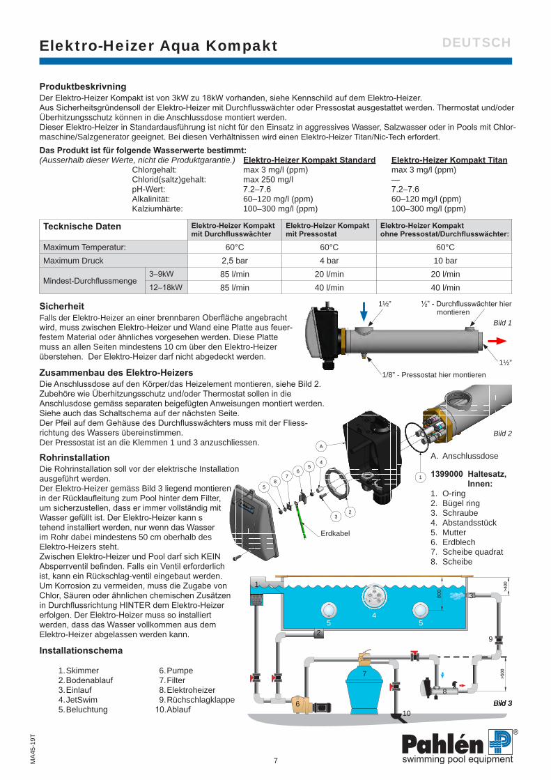
A. Anschlussdose
1399000 Haltesatz, Innen:1. O-ring2. Bügel ring3. Schraube4. Abstandsstück5. Mutter6. Erdblech7. Scheibe quadrat8. Scheibe
1. Skimmer 2. Bodenablauf 3. Einlauf 4. JetSwim 5. Beluchtung
6. Pumpe 7. Filter 8. Elektroheizer 9. Rüchschlagklappe 10. Ablauf
Bild 2
Erdkabel
1/8” - Pressostat hier montieren
Bild 1
½” - Durchflusswächter hier montieren
RohrinstallationDie Rohrinstallation soll vor der elektrische Installation ausgeführt werden.Der Elektro-Heizer gemäss Bild 3 liegend montieren in der Rücklaufleitung zum Pool hinter dem Filter, um sicherzustellen, dass er immer vollständig mit Wasser gefüllt ist. Der Elektro-Heizer kann s tehend installiert werden, nur wenn das Wasser im Rohr dabei mindestens 50 cm oberhalb des Elektro-Heizers steht.Zwischen Elektro-Heizer und Pool darf sich KEIN Absperrventil befinden. Falls ein Ventil erforderlich ist, kann ein Rückschlag-ventil eingebaut werden.Um Korrosion zu vermeiden, muss die Zugabe von Chlor, Säuren oder ähnlichen chemischen Zusätzen in Durchflussrichtung HINTER dem Elektro-Heizer erfolgen. Der Elektro-Heizer muss so installiert werden, dass das Wasser vollkommen aus dem Elektro-Heizer abgelassen werden kann.
Installationschema
SicherheitFalls der Elektro-Heizer an einer brennbaren Oberfläche angebracht wird, muss zwischen Elektro-Heizer und Wand eine Platte aus feuer- festem Material oder ähnliches vorgesehen werden. Diese Platte muss an allen Seiten mindestens 10 cm über den Elektro-Heizer überstehen. Der Elektro-Heizer darf nicht abgedeckt werden.
Zusammenbau des Elektro-HeizersDie Anschlussdose auf den Körper/das Heizelement montieren, siehe Bild 2. Zubehöre wie Überhitzungsschutz und/oder Thermostat sollen in die Anschlusdose gemäss separaten beigefügten Anweisungen montiert werden. Siehe auch das Schaltschema auf der nächsten Seite. Der Pfeil auf dem Gehäuse des Durchflusswächters muss mit der Fliess-richtung des Wassers übereinstimmen. Der Pressostat ist an die Klemmen 1 und 3 anzuschliessen.
ProduktbeskrivningDer Elektro-Heizer Kompakt ist von 3kW zu 18kW vorhanden, siehe Kennschild auf dem Elektro-Heizer. Aus Sicherheitsgründensoll der Elektro-Heizer mit Durchflusswächter oder Pressostat ausgestattet werden. Thermostat und/oder Überhitzungsschutz können in die Anschlussdose montiert werden. Dieser Elektro-Heizer in Standardausführung ist nicht für den Einsatz in aggressives Wasser, Salzwasser oder in Pools mit Chlor- maschine/Salzgenerator geeignet. Bei diesen Verhältnissen wird einen Elektro-Heizer Titan/Nic-Tech erfordert.
Das Produkt ist für folgende Wasserwerte bestimmt: (Ausserhalb dieser Werte, nicht die Produktgarantie.) Elektro-Heizer Kompakt Standard Elektro-Heizer Kompakt Titan Chlorgehalt: max 3 mg/l (ppm) max 3 mg/l (ppm) Chlorid(saltz)gehalt: max 250 mg/l — pH-Wert: 7.2–7.6 7.2–7.6 Alkalinität: 60–120 mg/l (ppm) 60–120 mg/l (ppm) Kalziumhärte: 100–300 mg/l (ppm) 100–300 mg/l (ppm)
Tecknische Daten Elektro-Heizer Kompakt mit Durchflusswächter
Elektro-Heizer Kompaktmit Pressostat
Elektro-Heizer Kompakt ohne Pressostat/Durchflusswächter:
Maximum Temperatur: 60°C 60°C 60°CMaximum Druck 2,5 bar 4 bar 10 bar
Mindest-Durchflussmenge3–9kW 85 l/min 20 l/min 20 l/min 12–18kW 85 l/min 40 l/min 40 l/min
Bild 3Bild 3Bild 3Bild 3

8
Elektro-Heizer Aqua KompaktM
A45
-19T
DEUTSCH
E10024-3130903
BrytareBrytare
MotorskyddMotorskydd
Termostat
Termostat
Pressostatellerflödesvakt
Pressostatellerflödesvakt
3~400VL1 L10L1NL2 L3
3~230VL1 L2 L3
Röd
Blå
Röd
Blå
Vit
Vit
3-poligöverhettnings-skydd
Överhett-ningsskydd
3~400VL1 L2 L3
2
12
11
1
A ( 1 : 1 )
Art.no.
Rev.no.
Scale
Designed by: Approved by:
Revised by: Date
Drawn by: Date
Drawing number
Assembly drawing no.
Surface treatment
part of ISO 2768-1 The tolerance class in accordance with this
E
Box 728, SE-194 27 Upplands Väsby, SwedenPhone +46 8 59411050, Fax +46 8 59086880
TS 2012-06-21
överhettningsskyddDemontering lock
M11668 0
A
This
doc
umen
t and
its
cont
ents
are
the
excl
usiv
e pr
oper
ty o
f Pah
léns
and
may
not
be
copi
ed,
repr
oduc
e d, t
rans
mitt
ed o
r com
mun
icat
ed to
a th
ird
party
, or u
sed
for a
ny p
urpo
se w
ithou
t writ
ten
perm
issi
on.
Cap
A ( 1 : 1 )
This
doc
umen
t and
its
cont
ents
are
the
excl
usiv
e pr
oper
ty o
f Pah
léns
and
may
not
be
copi
ed,
repr
oduc
e d, t
rans
mitt
ed o
r com
mun
icat
ed to
a th
ird
party
, or u
sed
for a
ny p
urpo
se w
ithou
t writ
ten
perm
issi
on.
Art.no.
Rev.no.
Scale
Designed by: Approved by:
Revised by: Date
Drawn by: Date
Drawing number
Assembly drawing no.
Surface treatment
part of ISO 2768-1 The tolerance class in accordance with this
E
Box 728, SE-194 27 Upplands Väsby, SwedenPhone +46 8 59411050, Fax +46 8 59086880
TS 2012-06-21
överhettningsskyddDemontering lock
M11668 0
A
Cap
Reset button
Schaltschema
Ein/Aus
Motorschütz Umwälzpumpe
1p Sicherheits-thermostat
PressostatStift 1 und 3oderDurchfluss-wächter
Thermostat
3~400V / 3~690V 3~400V / 3~690V
3~230V Ein/Aus
Motorschütz Umwälzpumpe
3p Sicherheits-thermostat, max 16A
Pressostat Stift 1 und 3oderDurchfluss-wächter
Thermostat
BU = blauRD = rotWH = weiss
WHRD
RDBU
WHBU
SchutzSchutz
Rückstelltaste
Bild 4
ElektroinstallationSämtliche Elektroinstallationsarbeiten dürfen ausschliesslich von Elektriker ausgeführt werden.Der elektrische Anschluss des Elektro-Heizers erfolgt je nach Ausführung über einen oder zwei Schütze. Siehe das Schalt- schema unten.Das Heizelement wird gemäss Bild 2 geerdet. Der elektrische Anschluss muss so ausgeführt sein, dass der Elektro-Heizer nicht ein-geschaltet werden kann, solange die Filter-Umwälzpumpe der Anlage nicht in Betrieb ist. Dazu ist der Schaltstrom für den Schütz bzw. die Schütze des Elektro-Heizers über den Schütz der Umwälzpumpe zu leiten.
Falls sich der Elektro-Heizer nicht einschalteta. Ist eine Sicherung durchgeschmolzen bzw. ausgelöst?b. Der Überhitzungsschutz kann ausgelöst haben.
- Den Schutz wegnehmen, siehe Bild 4. - Die Rückstelltaste an der Anschlussdose eindrücken. - Den Schutz wieder aufsetzen.
c. Hat der Pressostat (sofern vorhanden) nicht geschlossen? Der Pressostat ist auf einen Druck von 0,25 bar voreingestellt. Falls dieser Druck unter normalen Betriebsbedingungen nicht erreicht wird, muss die Rücklaufleitung zum Pool etwas verengt werden, um den Gegendruck in der Rücklaufleitung zu erhöhen.
d. Sicherstellen, dass die durch einen Pfeil auf dem Gehäuse gekennzeichnete Durchflussrichtung des Durchflusswächters mit der Fliessrichtung des Wassers übereinstimmt.
e. Der Thermostat auf eine höhere Temperatur einstellen.
BedienungBeim Gegenspülen oder bei der Reinigung des Filters ist der Elektro-Heizer abzuschalten.Beim Abstellen über längere Zeit und/oder Gefahr für Einfrieren muss der Heizer völlig von Wasser abgelassen werden.
Start 1. Die Umwälzpumpe für den Pool einschalten.2. Vor dem Einschalten des Elektro-Heizers überprüfen, dass das Wasser richtig durch die gesamte Anlage gepumpt wird.3. Um die Funktion des Elektro-Heizers zu überprüfen, das Einstellrad des Thermostat vor- und zurückdrehen und prüfen, ob
der Schütz des Thermostats ein- und ausschaltet. Um gegebenenfalls die Funktion des Durchfluss wächters oder des Presso-staten zu überprüfen, den Wasserdurchfluss durch den Elektro-Heizer mit einem Absperrventil blockieren und über prüfen, ob der Schütz abschaltet.
4. Dann die gewünschte Pooltemperatur einstellen.5. Jetzt heizt der Elektro-Heizer das Wasser im Pool auf die gewünschte Temperatur.

9
Aqua Компактный электронагревательM
A45
-19R
РУССКИЙ
Art.no.
Rev.no.
Scale
Designed by: Approved by:
Revised by: Date
Drawn by: Date
Drawing number
Assembly drawing no.
Surface treatment
part of ISO 2768-1 The tolerance class in accordance with this
E
Box 728, SE-194 27 Upplands Väsby, SwedenPhone +46 8 59411050, Fax +46 8 59086880
TS
TS 2007-12-12
Medium
Elvärmare kompakt 3-18kW
M10930 0
This
doc
umen
t and
its
cont
ents
are
the
excl
usiv
e pr
oper
ty o
f Pah
léns
and
may
not
be
copi
ed,
repr
oduc
e d, t
rans
mitt
ed o
r com
mun
icat
ed to
a th
ird
party
, or u
sed
for a
ny p
urpo
se w
ithou
t writ
ten
perm
issi
on.
148
97,4
206
173
1½”
1½”
Art.no.
Rev.no.
Scale
Designed by: Approved by:
Revised by: Date
Drawn by: Date
Drawing number
Assembly drawing no.
Surface treatment
part of ISO 2768-1 The tolerance class in accordance with this
E
Box 728, SE-194 27 Upplands Väsby, SwedenPhone +46 8 59411050, Fax +46 8 59086880
1399000OA 2008-09-02
ASA 2009-03-26
Elvärmare kompaktFästkit inre
jordning M10932 1
M10718139900XPlasticTerminal box1ADIN 7980 - 419941016A2Bricka FBB18M1086419940304SteelFyrkantsbricka17M1081814564220SteelJordbleck16ISO 4032 - M419930015A4Mutter M6M M4 25plast jord19950100PlasticDistansrör, vit plast14DIN 7985 (H) - M4x12-H19909221A2Skruv MRX M4x1213M10952147020PlasticFästring12O-ring 62x219970622NBR70O-ring 62x2 NBR7011
Drawing.no:Art.noMaterialTitle/ NameQty.Item.
This
doc
umen
t and
its
cont
ents
are
the
excl
usiv
e pr
oper
ty o
f Pah
léns
and
may
not
be
copi
ed,
repr
oduc
e d, t
rans
mitt
ed o
r com
mun
icat
ed to
a th
ird
party
, or u
sed
for a
ny p
urpo
se w
ithou
t writ
ten
perm
issi
on.
1
23
45
67
8
Jordkabel
5
A
>4
00
>5
00
80
0
1
4
2
3
55
7
6
8
9
10
РУССКИЙ
1/8” - Прессостат
Рис 1
½” - Датчик потока
6. Hacoc 7. Фильтр 8. Электронагреватель 9. Обратный клапан10. Водосток
Описание изделияКомпактный электронагреватель выпускается в виде моделей мощностью от 3 кВт до 18 кВт. Мощность электронагревателя указана на заводской этикетке на корпусе.Для обеспечения безопасности электронагреватель оборудован датчиком потока или датчиком давления. В соединительной коробке могут быть установлены термостат/или защита от перегрева.Стандартный нагреватель не предназначен для использования в агрессивной воде, соленой воде или в бассейнах, где применяется солевой хлоратор. В этих случаях следует использовать компактный электронагреватель в корпусе из титана, оборудованный ТЭНом, имеющим покрытие Nic-Tech. Такие электронагреватели имеют индекс “Т” в конце номера артикула.
Продукт предназначен для использования при следующих характеристиках воды:(Гарантия не распространяется на электронагреватели, эксплуатировавшиеся в воде с характеристиками за пределами нижеуказанных значений). Standard Стандартный Титан Содержание активного хлора: макс. 3 мг/л (ppm) макс. 3 мг/л (ppm) Содержание хлоридов: макс. 250 mg/l — Значение рН: 7.2–7.6 7.2–7.6 Щелочность: 60–120 мг/л (ppm) 60–120 мг/л (ppm) Кальциевая жесткость: 100–300 мг/л (ppm) 100–300 мг/л (ppm)
технические данные Компактный электронагревательс датчиком потока
Компактный электронагревательс прессостатом
Компактный электронагревательбез датчика потока/прессостата
Макс. температура: 60°C 60°C 60°CМакс. давление: 2,5 бар 4 бар 10 бар
Минимальный поток:
3–9 кВт 85 л/мин. 20 л/мин. 20 л/мин. 12–18 кВт 85 л/мин. 40 л/мин 40 л/мин.
1399000 Набор для внутреннего монтажа1. Уплотнительное кольцо2. Прижимное кольцо3. Винт4. Шайба толстая5. Гайка6. Скоба заземления7. Шайба четырехг- ранная8. Шайба
Рис 2
Кабель заземления
A. Соединительная коробка
БезопасностьЕсли нагреватель устанавливается возле стены из огнеопасного материала, то между нагревателем и стеной следует установить плиту из огнеупорного материала, например, асбеста. Эта плита должна отстоять не менее чем на 100 мм от корпуса самого нагревателя. Нагреватель нельзя накрывать, помещать внутри или около огнеопасного материала.
Сборка нагревателяКоробка соединения устанавливается на ТЭНе, как показано на рис. 2. Вспомогательное оборудование, такое как защита от перегрева и/или термостат устанавливаются в коробке согласно отдельным инструкциям, которые прилагаются к соответствующим наборам. См. также схему электрического подключения далее в данной инструкции. Датчик потока устанавливается таким образом, чтобы направление стрелки на корпусе совпадало с направлением потока воды, см. рис. 1.Прессостат подключается разъемами 1 и 3.
Подключение к контуру циркуляции водыВ первую очередь необходимо провести подключение к трубам контура циркуляции воды в бассейне, а уже потом электрическое подключение.Электрический нагреватель следует устанавливать на трубе, ведущей к впускной форсунке, после фильтра. Устанавливайте нагреватели в горизонта-льном положении, так чтобы они всегда были заполнены водой, см. рис. 3.Нагреватель может быть установлен и в вертика- льном положении, при условии, что уровень жидкости в трубах превышает уровень жидкости в нагревателе более, чем на 500 мм.Нельзя устанавливать запорный клапан между нагревателем и бассейном. При необходимости следует использовать обратный клапан. Дозировка хлора, кислоты или других химикатов должна осуществляться после нагревателя, чтобы избежать коррозии.При работе в климатических условиях с минусовыми температурами, нагреватель должен устанавливаться таким образом, чтобы из него можно было слить воду.
Схема подключения к контуру циркуляции воды
Рис 3
1. Скиммер2. Донный слив3. Форсунка4. Противоток JetSwim5. Прожектор

10
Aqua Компактный электронагревательM
A45
-19R
РУССКИЙ
E10024-3130903
BrytareBrytare
MotorskyddMotorskydd
Termostat
Termostat
Pressostatellerflödesvakt
Pressostatellerflödesvakt
3~400VL1 L10L1NL2 L3
3~230VL1 L2 L3
Röd
Blå
Röd
Blå
Vit
Vit
3-poligöverhettnings-skydd
Överhett-ningsskydd
3~400VL1 L2 L3
2
12
11
1
A ( 1 : 1 )
Art.no.
Rev.no.
Scale
Designed by: Approved by:
Revised by: Date
Drawn by: Date
Drawing number
Assembly drawing no.
Surface treatment
part of ISO 2768-1 The tolerance class in accordance with this
E
Box 728, SE-194 27 Upplands Väsby, SwedenPhone +46 8 59411050, Fax +46 8 59086880
TS 2012-06-21
överhettningsskyddDemontering lock
M11668 0
A
This
doc
umen
t and
its
cont
ents
are
the
excl
usiv
e pr
oper
ty o
f Pah
léns
and
may
not
be
copi
ed,
repr
oduc
e d, t
rans
mitt
ed o
r com
mun
icat
ed to
a th
ird
party
, or u
sed
for a
ny p
urpo
se w
ithou
t writ
ten
perm
issi
on.
Cap
A ( 1 : 1 )
This
doc
umen
t and
its
cont
ents
are
the
excl
usiv
e pr
oper
ty o
f Pah
léns
and
may
not
be
copi
ed,
repr
oduc
e d, t
rans
mitt
ed o
r com
mun
icat
ed to
a th
ird
party
, or u
sed
for a
ny p
urpo
se w
ithou
t writ
ten
perm
issi
on.
Art.no.
Rev.no.
Scale
Designed by: Approved by:
Revised by: Date
Drawn by: Date
Drawing number
Assembly drawing no.
Surface treatment
part of ISO 2768-1 The tolerance class in accordance with this
E
Box 728, SE-194 27 Upplands Väsby, SwedenPhone +46 8 59411050, Fax +46 8 59086880
TS 2012-06-21
överhettningsskyddDemontering lock
M11668 0
A
Cap
Reset button
РУССКИЙ
Электрическая схема
Вкл/выкл
Защитное реле мотора циркуляционный насос
Защита от перегрева
Прессостат (контакты 1 и 3) или датчик потока
Термостат
3~400B / 3~690B 3~400B / 3~690B
3~230B Вкл/выкл
Защитное реле мотора циркуляционный насос
Трёхполюсная защита от перегрева (макс. 16A)
Прессостат (контакты 1 и 3) или датчик потока
Термостат
BU = СинийRD = КрасныйWH = Белый
WHRD
RDBU
WHBU
Защитная крышка Защитная крышка
Кнопкаперезагрузки
Рис 4Если нагреватель не работает:a) Проверьте предохранители.б) Сработало реле защиты от перегрева: -Подденьте защитную крышку инструментом -Нажмите на кнопку перезагрузки в соединительной коробке -Установите обратно защитную крышкув) Не закрыто реле давления: Данное реле давления предварительно настроено на давление 0,25 бара. Если не удается достичь требуемого давления, возвратная труба в бассейн должна быть каким-нибудь образом укорочена, чтобы повысить обратное давление в обратной трубе. Нагреватель не будет работать, если обратное давление в системе циркуляции жидкости неправильно.г) Для реле потока предварительно задано минимальное значение потока 45 л/мин. Проверьте, чтобы стрелка направления потока жидкости в реле потока совпадала с реальным направление
УходПри обратной промывке и очистке фильтра подаваемое на нагреватель напряжение должно быть выключено.При отключении циркуляции и/или при минусовой температуре вся вода из электронагревателя должна быть удалена.
Электрическое подключениеПодключение к электросети должно осуществляться квалифицированным специалистом.Подключать нагреватель необходимо с помощью одного или двух контакторов, в зависимости от типа нагревателя, см. рисунок со схемой подключения. Подключите заземление к ТЭНу согласно рис. 2.Нагреватель необходимо подключать таким образом, чтобы напряжение на ТЭН не могло быть подано при выключенном циркуляционном насосе, т.е. контактор нагревателя должен быть подключен через контактор мотора насоса.
Включение электронагревателя1. Запустите насос, чтобы вода в бассейне циркулировала.2. Проверьте циркуляцию воды, прежде чем включать нагреватель.3. Проверьте нагреватель, повернув ручку термостата вперед и назад, и убедитесь, что его контактор включается
и выключается. Проверьте датчик потока/прессостат, перекрыв поток жидкости через нагреватель с помощью запорного клапана и убедитесь, что контактор обесточен.
4. Установите требуемую температуру.5. Теперь нагреватель будет нагревать воду в бассейне до желаемой температуры.

11
Art.no.
Rev.no.
Scale
Designed by: Approved by:
Revised by: Date
Drawn by: Date
Drawing number
Assembly drawing no.
Surface treatment
part of ISO 2768-1 The tolerance class in accordance with this
E
Box 728, SE-194 27 Upplands Väsby, SwedenPhone +46 8 59411050, Fax +46 8 59086880
TS
TS 2007-12-12
Medium
Elvärmare kompakt 3-18kW
M10930 0
This
doc
umen
t and
its
cont
ents
are
the
excl
usiv
e pr
oper
ty o
f Pah
léns
and
may
not
be
copi
ed,
repr
oduc
e d, t
rans
mitt
ed o
r com
mun
icat
ed to
a th
ird
party
, or u
sed
for a
ny p
urpo
se w
ithou
t writ
ten
perm
issi
on.
148
97,4
206
173
1½”
1½”
Art.no.
Rev.no.
Scale
Designed by: Approved by:
Revised by: Date
Drawn by: Date
Drawing number
Assembly drawing no.
Surface treatment
part of ISO 2768-1 The tolerance class in accordance with this
E
Box 728, SE-194 27 Upplands Väsby, SwedenPhone +46 8 59411050, Fax +46 8 59086880
1399000OA 2008-09-02
ASA 2009-03-26
Elvärmare kompaktFästkit inre
jordning M10932 1
M10718139900XPlasticTerminal box1ADIN 7980 - 419941016A2Bricka FBB18M1086419940304SteelFyrkantsbricka17M1081814564220SteelJordbleck16ISO 4032 - M419930015A4Mutter M6M M4 25plast jord19950100PlasticDistansrör, vit plast14DIN 7985 (H) - M4x12-H19909221A2Skruv MRX M4x1213M10952147020PlasticFästring12O-ring 62x219970622NBR70O-ring 62x2 NBR7011
Drawing.no:Art.noMaterialTitle/ NameQty.Item.
This
doc
umen
t and
its
cont
ents
are
the
excl
usiv
e pr
oper
ty o
f Pah
léns
and
may
not
be
copi
ed,
repr
oduc
e d, t
rans
mitt
ed o
r com
mun
icat
ed to
a th
ird
party
, or u
sed
for a
ny p
urpo
se w
ithou
t writ
ten
perm
issi
on.
1
23
45
67
8
Jordkabel
5
A
>4
00
>5
00
80
0
1
4
2
3
55
7
6
8
9
10
Calentador Aqua CompactM
A45
-19S
p
ESPAÑOL
1/8” - Coloque el presostato aquí
Dibujo 1
½” - Coloque el indicador de flujo aquí
1. Rebosaderos 2. Sumidero 3. Entrada 4. JetSwim 5. Iluminación 6. Bomba 7. Filtro 8. Calentador eléctrico 9. Válvula anti retorno10. Desagüe
A. Caja de conexiónKit de sujeción interior:(1399000)1. Junta tórica2. Anillo de retención3. Tornillo4. Tubo separador5. Tuerca6. Placa de tierra7. Arandela cuadrada8. Arandela
Dibujo 2
Cable de tierra
Descripción del productoEl calentador eléctrico Aqua Kompakt está disponible desde 3kW hasta 18kW, vea la placa descriptiva del producto. Por razones de seguridad el calentador eléctrico tiene que ir equipado con un indicador de flujo o un presostato.En la caja también se puede montar un termostato y/o una protección de sobrecalentamiento.El calentador de Aqua Kompakt tiene un diseño estándar que no es apto para aguas agresivas, agua salada o piscinas con clorador/colardor salino. Para estos casos se necesita un calentador eléctrico Aqua Kompakt Titan.
El producto está destinada para los siguientes valores de agua;(La garantía no cubre valores que están fuera de estos límites.) Clt. Estándard Clt. Titan Contenido de cloruros: max 3 mg/l (ppm) max 3 mg/l (ppm) Contenido de cloruro (sal): max 250 mg/l — Valor pH: 7.2–7.6 7.2–7.6 Alcalinidad: 60–120 mg/l (ppm) 60–120 mg/l (ppm) Dureza de calcio: 100–300 mg/l (ppm) 100–300 mg/l (ppm)
Datos técnicos con indicador de flujo con presostato sin indicador de flujo/presostato
Temperatura máxima: 60°C 60°C 60°CPresión máxima. 2,5 bar 4 bar 10 barFlujo mín. 3–9kW: 85 l/min 20 l/min 20 l/min Flujo mín. 12–18kW: 85 l/min 40 l/min 40 l/min
SeguridadSi el calentador va a ser instalado contra material inflamable, coloque una tabla resistente al fuego o parecido ente el calentador y la pared.La tabla debe salir 10 cm de las dimensiones exteriores del calentador. No cubrir el calentador.
Instalación del calentador eléctricoColoque la caja de conexión en la cubierta/cartucho, vea el dibujo 2.Monte la protección de sobrecalentamiento y/o el termostato en la caja según las instrucciones que los acompañan. Vean también el esquema eléctrico en la página siguiente.Monte el indicador de flujo de forma que la flecha en la carcasa del indicador coincida con la dirección del flujo de agua, vea el dibujo 1.Conecte el presostato a través de la placa 1 y 3.
Instalación de tuberíaInstale la tubería antes de proceder con la instalación eléctrica.Monte el calentador horizontalmente en el conducto de retorno de la piscina después del filtro, para que siempre quede lleno de agua, vea el dibujo 3.
También se puede colocar el calentador verticalmente, siempre que el agua en las tuberías quede 50 cm por encima del calentador NO instale una válvula de cierre entre el calenta- dor y la piscina. Si se requiere una válvula, instale una válvula anti retorno.Dosifica el cloro, ácido o parecido en el flujo del agua QUE SALE del calentador para evitar corrosión.Haga la instalación de forma que permita el vaciado completo del calentador.
Esquema de instalación
Dibujo 3

12
E10024-3130903
BrytareBrytare
MotorskyddMotorskydd
Termostat
Termostat
Pressostatellerflödesvakt
Pressostatellerflödesvakt
3~400VL1 L10L1NL2 L3
3~230VL1 L2 L3
Röd
Blå
Röd
Blå
Vit
Vit
3-poligöverhettnings-skydd
Överhett-ningsskydd
3~400VL1 L2 L3
2
12
11
1
A ( 1 : 1 )
Art.no.
Rev.no.
Scale
Designed by: Approved by:
Revised by: Date
Drawn by: Date
Drawing number
Assembly drawing no.
Surface treatment
part of ISO 2768-1 The tolerance class in accordance with this
E
Box 728, SE-194 27 Upplands Väsby, SwedenPhone +46 8 59411050, Fax +46 8 59086880
TS 2012-06-21
överhettningsskyddDemontering lock
M11668 0
A
This
doc
umen
t and
its
cont
ents
are
the
excl
usiv
e pr
oper
ty o
f Pah
léns
and
may
not
be
copi
ed,
repr
oduc
e d, t
rans
mitt
ed o
r com
mun
icat
ed to
a th
ird
party
, or u
sed
for a
ny p
urpo
se w
ithou
t writ
ten
perm
issi
on.
Cap
A ( 1 : 1 )
This
doc
umen
t and
its
cont
ents
are
the
excl
usiv
e pr
oper
ty o
f Pah
léns
and
may
not
be
copi
ed,
repr
oduc
e d, t
rans
mitt
ed o
r com
mun
icat
ed to
a th
ird
party
, or u
sed
for a
ny p
urpo
se w
ithou
t writ
ten
perm
issi
on.
Art.no.
Rev.no.
Scale
Designed by: Approved by:
Revised by: Date
Drawn by: Date
Drawing number
Assembly drawing no.
Surface treatment
part of ISO 2768-1 The tolerance class in accordance with this
E
Box 728, SE-194 27 Upplands Väsby, SwedenPhone +46 8 59411050, Fax +46 8 59086880
TS 2012-06-21
överhettningsskyddDemontering lock
M11668 0
A
Cap
Reset button
Calentador Aqua CompactM
A45
-19S
p
ESPAÑOL
Esquema eléctrico
Interruptor
Protector del motor para bomba de circulación
1p Protección contra sobre-calentamiento
Presostato pin 1 y 3 o indicador de flujo
Termostato
3~400V / 3~690V 3~400V / 3~690V
3~230V Interruptor
Protector del motor para bomba de circulación
3p Protección contra sobre-calentamientomáx. 16A
Presostato pin 1 y 3 o indicador de flujo
Termostato
BU = azulRD = rojoWH = blanco
WHRD
RDBU
WHBU
Capucha de protección Capucha de protección
Botón de reajuste
Dibujo 4
Si el calentador no arrancaa. Compruebe los fusiles.b. La protección contra sobrecalentamiento puede haber sido
activado:c. Quite la capucha de protección, vea dibujo 4.
Presione el botón de reajuste en la caja de conexión. Coloque la protección de nuevo.d. El presostato (en caso de que hubiera) no está cerrado. El presostato está prefijado en 0,25 bar. Si no se obtiene la presión
deseada, presione ligeramente el conducto de retorno para aumentar la contrapresión.e. Si hay un indicador de flujo montado, compruebe que la flecha concuerda con la dirección del flujo del agua.f. Ajuste el termostato a una temperatura superior.
MantenimientoApague el calentador durante el retrolavado y enjuague del filtro.Drenar completamente el agua del calentador si va a estar inactivo durante un largo periodo.
Instalación eléctricaLa instalación eléctrica debe ser realizada por un electricista profesional.Conecte el calentador sobre uno o dos contactores según el diseño del calentador. Vea el esquema eléctrico abajo.El cartucho eléctrico debe estar conectado a tierra, vea el dibujo 2.Realice la instalación de manera que el activador hacia el contactor del calentador este controlado por el contactor de la bomba (no se debe poder encender el calentador si la bomba de circulación está operativa.).
Aranque1. Arranque la bomba para circular el agua de la piscina.2. Compruebe que el agua circule con normalidad en la instalación antes de encender el calentador.3. Compruebe la función del calentador girando la rueda del termostato hacia atrás y adelante verificando que el contactor se
enciende y apaga. Compruebe posibles indicadores de flujo o presostatos cortando el flujo a través del calentador (con una válvula de cierre). El contactor debe apagarse.
4. Ajuste la temperatura de la piscina con el mando del termostato.5. El calentador ahora debe calentar el agua de la piscina a la
temperatura deseada.

13
Riscaldatore elettrico Aqua CompactM
A45
-19I
t
ITALIANO
Art.no.
Rev.no.
Scale
Designed by: Approved by:
Revised by: Date
Drawn by: Date
Drawing number
Assembly drawing no.
Surface treatment
part of ISO 2768-1 The tolerance class in accordance with this
E
Box 728, SE-194 27 Upplands Väsby, SwedenPhone +46 8 59411050, Fax +46 8 59086880
TS
TS 2007-12-12
Medium
Elvärmare kompakt 3-18kW
M10930 0
This
doc
umen
t and
its
cont
ents
are
the
excl
usiv
e pr
oper
ty o
f Pah
léns
and
may
not
be
copi
ed,
repr
oduc
e d, t
rans
mitt
ed o
r com
mun
icat
ed to
a th
ird
party
, or u
sed
for a
ny p
urpo
se w
ithou
t writ
ten
perm
issi
on.
148
97,4
206
173
1½”
1½”
Art.no.
Rev.no.
Scale
Designed by: Approved by:
Revised by: Date
Drawn by: Date
Drawing number
Assembly drawing no.
Surface treatment
part of ISO 2768-1 The tolerance class in accordance with this
E
Box 728, SE-194 27 Upplands Väsby, SwedenPhone +46 8 59411050, Fax +46 8 59086880
1399000OA 2008-09-02
ASA 2009-03-26
Elvärmare kompaktFästkit inre
jordning M10932 1
M10718139900XPlasticTerminal box1ADIN 7980 - 419941016A2Bricka FBB18M1086419940304SteelFyrkantsbricka17M1081814564220SteelJordbleck16ISO 4032 - M419930015A4Mutter M6M M4 25plast jord19950100PlasticDistansrör, vit plast14DIN 7985 (H) - M4x12-H19909221A2Skruv MRX M4x1213M10952147020PlasticFästring12O-ring 62x219970622NBR70O-ring 62x2 NBR7011
Drawing.no:Art.noMaterialTitle/ NameQty.Item.
This
doc
umen
t and
its
cont
ents
are
the
excl
usiv
e pr
oper
ty o
f Pah
léns
and
may
not
be
copi
ed,
repr
oduc
e d, t
rans
mitt
ed o
r com
mun
icat
ed to
a th
ird
party
, or u
sed
for a
ny p
urpo
se w
ithou
t writ
ten
perm
issi
on.
1
23
45
67
8
Jordkabel
5
A
>4
00
>5
00
80
0
1
4
2
3
55
7
6
8
9
10
1/8” - Montare qui il pressostato
Figura 1
½” - Montare qui il flussostato
1. Scarico del troppo pieno 2. Scarico inferiore 3. Immissione 4. JetSwim 5. Illuminazione 6. Pompa 7. Filtro 8. Riscaldatore elettrico 9. Valvola di ritegno10. Scarico
A. Scatola di derivazioneKit fissaggio interno:(1399000)1. O-ring2. Anello di fissaggio3. Vite4. Tubo distanziale5. Dado6. Piastra di terra7. Rondella quadrata8. Rondella
Figura 2
Cavo di terra
Descrizione del prodottoIl Riscaldatore Compact è disponibile a partire da 3kW e fino a 18kW, vedere l’etichetta del tipo sul prodotto. Per questioni di sicurezza, dotare il riscaldatore elettrico di un pressostato o un flussostato.Nella scatola può essere montato il termostato o/e la protezione antisurriscaldamento.Il Riscaldatore elettrico Compact nella sua versione di serie non è previsto per l’utilizzo in acqua chimicamente aggressiva, acqua salata o in piscine con generatore salinico/macchina per il cloro. Per tali installazioni è consigliabile il Riscaldatore elettrico Compact Titan.
Il prodotto è previsto per i seguenti valori dell’acqua:Se i valori non rientrano in questi parametri, la garanzia del prodotto decade. Risc Compact Standard Risc Compact Titan Concentrazione di cloro: max 3 mg/l (ppm) max 3 mg/l (ppm) Concentrazione di cloruro (sale): max 250 mg/l — pH: 7.2–7.6 7.2–7.6 Alcalinità: 60–120 mg/l (ppm) 60–120 mg/l (ppm) Durezza dell’acqua: 100–300 mg/l (ppm) 100–300 mg/l (ppm)
Caratteristiche tecniche con flussostato con pressostato senza flussostato/ pressostato
Temperatura max: 60°C 60°C 60°CPressione max: 2,5 bar 4 bar 10 barFlusso min 3–9kW: 85 l/min 20 l/min 20 l/min Flusso min 12–18kW: 85 l/min 40 l/min 40 l/min
SicurezzaSe il riscaldatore viene appoggiato a materiale infiammabile, montare una piastra ignifuga o simile tra il riscaldatore e la parete.La piastra deve coprire una superficie di 10 cm oltre le dimensioni esterne del riscaldatore. Non coprire il riscaldatore.
Montaggio del riscaldatoreLa scatola di derivazione si monta sul mantello/cartuccia, vedere la figura 2.Gli accessori, come la protezione antisurriscaldamento e/o il termostato, si montano nella scatola secondo le istruzioni specifiche allegate. Vedere anche lo schema elettrico alla prossima pagina delle presenti istruzioni.Montare il flussostato in modo che la freccia sul corpo del flussostato corrisponda alla direzione del flusso dell’acqua, vedere la fig. 1.Collegare il pressostato tramite le pareti 1 e 3
Installazione dei tubiInstallare i tubi prima di montare i componenti elettrici.Montare il riscaldatore appoggiato al tubo di ritorno alla piscina a valle del filtro, in modo che sia sempre interamente riempito di acqua, vedere la fig. 3.Il riscaldatore può essere posizionato in piedi, a condizione che sia montato in modo che l’acqua nel tubo rimanga almeno 50 cm sopra il riscaldatore.NON montare valvole di intercettazione tra il riscaldatore e la piscina. Se è necessaria una valvola, installare una valvola di ritegno.Il dosaggio di cloro, ossigeno e simile va fatto A VALLE del riscaldatore, nella direzione del flusso, per evitare corrosione.Effettuare l’installazione in modo che il riscaldatore possa prelevare tutta l’acqua.
Schema di montaggio
Figura 3

14
Riscaldatore elettrico Aqua CompactM
A45
-19I
t
ITALIANO
E10024-3130903
BrytareBrytare
MotorskyddMotorskydd
Termostat
Termostat
Pressostatellerflödesvakt
Pressostatellerflödesvakt
3~400VL1 L10L1NL2 L3
3~230VL1 L2 L3
Röd
Blå
Röd
Blå
Vit
Vit
3-poligöverhettnings-skydd
Överhett-ningsskydd
3~400VL1 L2 L3
2
12
11
1
A ( 1 : 1 )
Art.no.
Rev.no.
Scale
Designed by: Approved by:
Revised by: Date
Drawn by: Date
Drawing number
Assembly drawing no.
Surface treatment
part of ISO 2768-1 The tolerance class in accordance with this
E
Box 728, SE-194 27 Upplands Väsby, SwedenPhone +46 8 59411050, Fax +46 8 59086880
TS 2012-06-21
överhettningsskyddDemontering lock
M11668 0
A
This
doc
umen
t and
its
cont
ents
are
the
excl
usiv
e pr
oper
ty o
f Pah
léns
and
may
not
be
copi
ed,
repr
oduc
e d, t
rans
mitt
ed o
r com
mun
icat
ed to
a th
ird
party
, or u
sed
for a
ny p
urpo
se w
ithou
t writ
ten
perm
issi
on.
Cap
A ( 1 : 1 )
This
doc
umen
t and
its
cont
ents
are
the
excl
usiv
e pr
oper
ty o
f Pah
léns
and
may
not
be
copi
ed,
repr
oduc
e d, t
rans
mitt
ed o
r com
mun
icat
ed to
a th
ird
party
, or u
sed
for a
ny p
urpo
se w
ithou
t writ
ten
perm
issi
on.
Art.no.
Rev.no.
Scale
Designed by: Approved by:
Revised by: Date
Drawn by: Date
Drawing number
Assembly drawing no.
Surface treatment
part of ISO 2768-1 The tolerance class in accordance with this
E
Box 728, SE-194 27 Upplands Väsby, SwedenPhone +46 8 59411050, Fax +46 8 59086880
TS 2012-06-21
överhettningsskyddDemontering lock
M11668 0
A
Cap
Reset button
Schema elettrico
Interruttore
Salvamotore pompa di ricircolo
1p Protezionesurriscalda-mento
Pressostato pin 1 e 3
oppure flussostato
Termostato
3~400V / 3~690V 3~400V / 3~690V
3~230V Interruttore
Salvamotore pompa di ricircolo
3p Protezione surriscalda-mento,max 16A
Pressostato pin 1 e 3 oppure flussostato
Termostato
BU = bluRD = rossoWH = bianco
WHRD
RDBU
WHBU
Coperchio della protezione Coperchio della protezione
Ripristino
Figura 4Se il riscaldatore non si avviaa. Controllare i fusibili.b. La protezione da surriscaldamento potrebbe essere scattata:
rimuovere il coperchio della protezione, vedere la fig. 4.c. Premere il pulsante di ripristino sulla scatola di derivazione.
Rimontare il coperchio.d. Il pressostato, se montato, non è sigillato: il pressostato è pre-impostato su 0,25 bar. Se non raggiunge la pressione
corretta, il tubo di ritorno alla piscina va ristretto leggermente per aumentarne la pressione.e. Controllare che l’eventuale flussostato sia montato con la freccia in direzione del flusso dell’acqua.f. Impostare il termostato a una temperatura superiore.
CuraPer la pulizia e il lavaggio del filtro, chiudere l’apporto di acqua al riscaldatore.Per lunghi periodi di inattività e/o in caso di rischio di gelate, drenare completamente il riscaldatore elettrico dall’acqua.
Installazione elettricaL’installazione elettrica va effettuata da un elettricista autorizzato.Collegare il riscaldatore su uno o due contattori, a seconda della configurazione del riscaldatore. Vedere lo schema elettrico sotto.Collegare a massa le cartucce elettriche secondo quanto indicato alla fig. 2.L’installazione va fatta in modo che la corrente di comando al connettore del riscaldatore abbia la precedenza rispetto al connet-tore della pompa (il riscaldatore non deve poter essere attivato se la pompa di ricircolo dell’impianto non è in funzione).
Avvio1. Avviare la pompa di ricircolo dell’acqua della piscina.2. Controllare che l’acqua circoli normalmente nell’impianto prima di inserire il riscaldatore.3. Effettuare una prova di funzionamento del riscaldatore girando la manopola del termostato avanti e indietro e controllando
che i connettori del termostato si attivino e si disattivino. Controllare il flussostato o il pressostato chiudendo il flusso che attraversa il riscaldatore (con una valvola di blocco). Il connettore deve staccarsi.
4. Impostare la temperatura desiderata della piscina agendo sulla manopola.5. Ora il riscaldatore porterà l’acqua della piscina alla temperatura desiderata

15
Art.no.
Rev.no.
Scale
Designed by: Approved by:
Revised by: Date
Drawn by: Date
Drawing number
Assembly drawing no.
Surface treatment
part of ISO 2768-1 The tolerance class in accordance with this
E
Box 728, SE-194 27 Upplands Väsby, SwedenPhone +46 8 59411050, Fax +46 8 59086880
TS
TS 2007-12-12
Medium
Elvärmare kompakt 3-18kW
M10930 0
This
doc
umen
t and
its
cont
ents
are
the
excl
usiv
e pr
oper
ty o
f Pah
léns
and
may
not
be
copi
ed,
repr
oduc
e d, t
rans
mitt
ed o
r com
mun
icat
ed to
a th
ird
party
, or u
sed
for a
ny p
urpo
se w
ithou
t writ
ten
perm
issi
on.
148
97,4
206
173
1½”
1½”
Art.no.
Rev.no.
Scale
Designed by: Approved by:
Revised by: Date
Drawn by: Date
Drawing number
Assembly drawing no.
Surface treatment
part of ISO 2768-1 The tolerance class in accordance with this
E
Box 728, SE-194 27 Upplands Väsby, SwedenPhone +46 8 59411050, Fax +46 8 59086880
1399000OA 2008-09-02
ASA 2009-03-26
Elvärmare kompaktFästkit inre
jordning M10932 1
M10718139900XPlasticTerminal box1ADIN 7980 - 419941016A2Bricka FBB18M1086419940304SteelFyrkantsbricka17M1081814564220SteelJordbleck16ISO 4032 - M419930015A4Mutter M6M M4 25plast jord19950100PlasticDistansrör, vit plast14DIN 7985 (H) - M4x12-H19909221A2Skruv MRX M4x1213M10952147020PlasticFästring12O-ring 62x219970622NBR70O-ring 62x2 NBR7011
Drawing.no:Art.noMaterialTitle/ NameQty.Item.
This
doc
umen
t and
its
cont
ents
are
the
excl
usiv
e pr
oper
ty o
f Pah
léns
and
may
not
be
copi
ed,
repr
oduc
e d, t
rans
mitt
ed o
r com
mun
icat
ed to
a th
ird
party
, or u
sed
for a
ny p
urpo
se w
ithou
t writ
ten
perm
issi
on.
1
23
45
67
8
Jordkabel
5
A
>4
00
>5
00
80
0
1
4
2
3
55
7
6
8
9
10
Aqua Kompakt elektryczne podgrzewacze wodyM
A45
-19P
POLSKI
1/8” - Miejsce montażu presostatu
Rys 1
½”- Miejsce montażu czujnika przepływu
1. Rura przelewowa 2. Odpływ denny 3. Wlot 4. JetSwim 5. Oświetlenie
1. O-ring2. Pierścień mocujący3. Śruba4. Rura dystansowa5. Nakrętka6. Blaszka montażowa7. Podkładka kwadratowa8. Podkładka
Rys 2
Uziemienie
Opis produktuAqua Kompakt elektryczne podgrzewacze wody są dostępne w zakresie mocy od 3kW do 18Kw. Zobacz tabliczka znamionowa wyrobu. Ze względów bezpieczeństwa podgrzewacz należy zaopatrzyć w czujnik przepływu lub presostat.W puszce można zamontować termostat i/lub zabezpieczenie przed przegrzaniem.Kompaktowy elektryczny podgrzewacz wody w wersji standardowej nie jest przeznaczony do stosowania w wodzie agresywnej (kwaśnej), słonej ani w basenach wyposażonych w urządzenie do chlorowania wody/ generator soli. W takich sytuacjach należy zastosować Kompaktowy elektryczny podgrzewacz wody Titan.
Wyrób jest przeznaczony do stosowania w wodzie o następujących parametrach:(W przypadku wartości wykraczających poza podane zakresy gwarancja nie obowiązuje.) Kompakt Standard Kompakt Titan Zawartość chloru: maks. 3 mg/l (ppm) maks. 3 mg/l (ppm) Zawartość chlorku(soli): maks. 250 mg/l — pH: 7.2–7.6 7.2–7.6 Zasadowość: 60–120 mg/l (ppm) 60–120 mg/l (ppm) Twardość wapniowa: 100–300 mg/l (ppm) 100–300 mg/l (ppm)
Dane techniczne Podgrzewacz kompaktowyz czujnikiem przepływu
Podgrzewacz kompaktowyz presostatem
Podgrzewacz kompaktowy bez czujnika przepływu/presostatu
Maks.temperatura: 60°C 60°C 60°CMaks. ciśnienie: 2,5 bar 4 bar 10 barMin. przepływ 3–9kW: 85 l/min 20 l/min 20 l/min Min. przepływ 12–18kW: 85 l/min 40 l/min 40 l/min
UziemienieW przypadku umieszczenia podgrzewacza przy materiale łatwopalnym należy zastosować płytę ognioodporną lub podobną pomiędzy podgrzewaczem a ścianą.Płyta powinna wystawać 10 cm poza zewnętrzne wymiary pogdrzewacza. Podgrzewacza nie wolno przykrywać.
Składanie podgrzewaczaZamontować puszkę łączeniową na płaszczu/grzałce, zobacz rys.2.Akcesoria, takie jak zabezpieczenie przed przegrzaniem i/lub termostat, należy zamontować w puszce łączeniowej zgodnie z oddzielnymi instrukcjami dostarczonymi wraz z tymi urządzeniami. Zobacz także schemat podłączeń elektrycznych na następnej stronie niniejszej instrukcji.Czujnik przepływu należy zamontować w taki sposób, aby strzałka na jego obudowie była zgodna z kierunkiem przepływu wody, zobacz rys. 1.Presostat należy podłączyć do zacisków 1 i 3.
Montaż rurMontaż rur należy wykonać przed instalacją elektryczną.Podgrzewacz należy zamontować poziomo na przewodzie powrotnym do basenu za filtrem w taki sposób, aby był on zawsze całkowicie wypełniony wodą, zobacz rys. 3. Podgrzewacz można umieścić w pozycji pionowej, pod warunkiem, że zostanie zamontowany w taki sposób, aby poziom wody w rurach znajdował się na wysokości co najmniej 50 cm nad podgrzewaczem. NIE instalować zaworu odcinającego między podgrzewaczem a basenem. Jeśli wymagany jest zawór, należy zastosować zawór zwrotny.Chlor, kwas itp. należy dozować ZA podgrzewaczem w kierunku przepływu wody w celu uniknięcia korozji. Instalacja musi zostać tak wykonana, aby możliwe było spuszczenie z podgrzewacza całej wody.
Schemat instalacyjny
Rys 3
A. Puszka łączeniowaZestaw montażowy wewnątrz: (1399000)
6. Pompa 7. Filtr 8. Podgrzewacz elektryczny 9. Zawór zwrotny10.Kanalizacja

16
E10024-3130903
BrytareBrytare
MotorskyddMotorskydd
Termostat
Termostat
Pressostatellerflödesvakt
Pressostatellerflödesvakt
3~400VL1 L10L1NL2 L3
3~230VL1 L2 L3
Röd
Blå
Röd
Blå
Vit
Vit
3-poligöverhettnings-skydd
Överhett-ningsskydd
3~400VL1 L2 L3
2
12
11
1
A ( 1 : 1 )
Art.no.
Rev.no.
Scale
Designed by: Approved by:
Revised by: Date
Drawn by: Date
Drawing number
Assembly drawing no.
Surface treatment
part of ISO 2768-1 The tolerance class in accordance with this
E
Box 728, SE-194 27 Upplands Väsby, SwedenPhone +46 8 59411050, Fax +46 8 59086880
TS 2012-06-21
överhettningsskyddDemontering lock
M11668 0
A
This
doc
umen
t and
its
cont
ents
are
the
excl
usiv
e pr
oper
ty o
f Pah
léns
and
may
not
be
copi
ed,
repr
oduc
e d, t
rans
mitt
ed o
r com
mun
icat
ed to
a th
ird
party
, or u
sed
for a
ny p
urpo
se w
ithou
t writ
ten
perm
issi
on.
Cap
A ( 1 : 1 )
This
doc
umen
t and
its
cont
ents
are
the
excl
usiv
e pr
oper
ty o
f Pah
léns
and
may
not
be
copi
ed,
repr
oduc
e d, t
rans
mitt
ed o
r com
mun
icat
ed to
a th
ird
party
, or u
sed
for a
ny p
urpo
se w
ithou
t writ
ten
perm
issi
on.
Art.no.
Rev.no.
Scale
Designed by: Approved by:
Revised by: Date
Drawn by: Date
Drawing number
Assembly drawing no.
Surface treatment
part of ISO 2768-1 The tolerance class in accordance with this
E
Box 728, SE-194 27 Upplands Väsby, SwedenPhone +46 8 59411050, Fax +46 8 59086880
TS 2012-06-21
överhettningsskyddDemontering lock
M11668 0
A
Cap
Reset button
Aqua Kompakt elektryczne podgrzewacze wodyM
A45
-19P
POLSKI
Schemat podłączeń elektrycznych
Wyłącznik
Zabezpieczenie silnika pompy obiegowej
1p Zabezpiec-zenie przed przegrzaniem
Presostat pin 1 i 3 lub czujnik przepływu
Termostat
3~400V / 3~690V 3~400V / 3~690V
3~230V Wyłącznik
Zabezpieczenie silnika pompy obiegowej
3p Zabezpiec-zenie przed przegrzaniem, maks. 16A
Presostat pin 1 i 3 lub czujnik przepływu
Termostat
BU = niebieskiRD = czerwonyWH = biały
WHRD
RDBU
WHBU
Kapturek ochronnyKapturek ochronny
Przycisk resetowania
Rys 4Jeśli podgrzewacz nie uruchamia sięa. Sprawdzić bezpieczniki.b. Możliwe, że uaktywniła się ochrona przed przegrzaniem:c. Zdjąć kapturek ochronny, zobacz rys. 4.
Nacisnąć przycisk resetowania znajdujący się na puszce łączeniowej. Ponownie założyć kapturek.
d. Presostat, jeśli został zainstalowany, nie jest zamknięty: Presostat jest fabrycznie ustawiony na 0,25 bara. Jeśli nie zostanie osiągnięte właściwe ciśnienie, przewód powrotny do basenu zostanie nieznacznie zdławiony w celu zwiększenia przeciwciśnienia w przewodzie powrotnym.
e. Sprawdzić, czy czujnik przepływu został zamontowany w taki sposób, aby strzałka na obudowie czujnika była zgodna z kierunkiem przepływu wody.
f. Przestawić termostat na wyższą temperaturę.
KonserwacjaPodczas płukania zwrotnego i czyszczenia filtra należy wyłączyć prąd zasilający podgrzewacz.W przypadku wyłączenia na dłuższy okres i/lub ryzyka zamarznięcia należy całą wodę odprowadzić z podgrzewacza.
Instalacja elektrycznaInstalacja elektryczna może zostać wykonana wyłącznie przez uprawnionego elektryka.Podgrzewacz elektryczny należy podłączyć poprzez jeden lub dwa styczniki, w zależności od wersji podgrzewacza. Zobacz schemat podłączeń elektrycznych poniżej. Grzałkę należy uziemić w sposób przedstawiony na rys. 2.Instalację należy wykonać w taki sposób, aby prąd sterujący stycznikiem podgrzewacza został poprowadzony przez stycznik pompy (nie może być możliwości włączenia podgrzewacza bez jednoczesnej pracy pompy obiegowej w instalacji).
Uruchomienie1. Uruchomić pompę do obiegu wody basenowej.2. Sprawdzić, czy cyrkulacja wody w instalacji jest normalna przed włączeniem prądu zasilającego podgrzewacz. 3. Sprawdzić działanie podgrzewacza przekręcając pokrętło termostatu w jedną i w drugą stronę oraz sprawdzić, czy stycznik
termostatu włącza się i wyłącza. Czujnik przepływu lub presostat, jeśli zostały zamontowane, należy sprawdzić zamykając przepływ wody przez podgrzewacz (za pomocą zaworu odcinającego). Stycznik powinien wówczas się wyłączyć.
4. Ustawić żądaną temperaturę wody w basenie za pomocą pokrętła termostatu.5. Podgrzewacz podgrzeje teraz wodę w basenie do żądanej temperatury.

سخان كهربائي صغير الحجم
MA
45-1
9A
العربية
Art.no.
Rev.no.
Scale
:ybdevorppA:ybdengiseD
Revised by: Date
Drawn by: Date
Drawing number
Assembly drawing no.
Surface treatment
part of ISO ۱-۲۷٦۸ The tolerance class in accordance with this
E
Box ۷۲۸, SE۲۷ ۱۹٤- Upplands Väsby, SwedenPhone ٥۹٤۱۱۰٥۰ ۸ ٤٦+, Fax ٥۹۰۸٦۸۸۰ ۸ ٤٦+
۱۳۹۹۰۰۰OA ۰۲-۰۹-۲۰۰۸
ASA ۲٦-۰۳-۲۰۰۹
Elvärmare kompaktFästkit inre
jordning M۱۰۹۳۲ ۱
M۱۰۷۱۸۱۳۹۹۰۰XPlasticTerminal box۱ADIN ٤ - ۷۹۸۰۱۹۹٤۱۰۱٦A۲Bricka FBB۱۸M۱۰۸٦٤۱۹۹٤۰۳۰٤SteelFyrkantsbricka۱۷M۱۰۸۱۸۱٤٥٦٤۲۲۰SteelJordbleck۱٦ISO ٤۰۳۲ - M٤۱۹۹۳۰۰۱٥A٤Mutter M٦M M٤ ۲٥plast jord۱۹۹٥۰۱۰۰PlasticDistansrör, vit plast۱٤DIN ۷۹۸٥ (H) - M٤x-۱۲H۱۹۹۰۹۲۲۱A۲Skruv MRX M٤x۱۲۱۳M۱۰۹٥۲۱٤۷۰۲۰PlasticFästring۱۲O-ring ٦۲x۲۱۹۹۷۰٦۲۲NBR۷۰O-ring ٦۲x۲ NBR۷۰۱۱
Drawing.no:Art.noMaterialTitle/ NameQty.Item.
This
docu
men
t and
itsco
nten
tsar
eth
eex
clus
ive
prop
erty
ofP
ahlé
nsan
dm
ayno
t be
copi
ed,
repr
oduc
e d, t
rans
mitt
edor
com
mun
icat
edto
ath
irdpa
rty,o
ruse
dfo
rany
purp
ose
with
outw
ritte
npe
rmis
sion
.
۱
۲۳
٤٥
٦۷
۸
كبل أرضي
٥
أ
>
٤ ۰۰
>
٥۰۰
۸۰۰
1
4
2
3
55
7
6
8
9
10الصورة 3
17
1- مكشطة2- الصرف الرئيسي
3- مدخلJetSwim -4
5- لمبة6- مضخة
7- فلتر8- سخان كهربائي
9- صمام عدم رجوع10- صرف
وصف المنتجيتوفر السخان الكهربائي صغير الحجم بمخرجات من 3 كيلووات إلى 18 كيلووات، راجع لوحة التعريف الموجودة على جسم الجهاز.
ألسباب تتعلق بالسالمة، يأتي السخان مزوًدا بمفتاح تدفق أو مفتاح ضغط. في صندوق التوصيل، يمكن تركيب ترموستات و/أو أداة التحكم في الحد من زيادة درجة الحرارة. يجب عدم استخدام السخان العادي في المياه العدوانية أو المياه المالحة أو في حمامات السباحة حيث ُيستخدم الملح/جهاز الكلورة. هذه الظروف
تتطلب استخدام سخان كهربائي صغير الحجم مصنوع من التيتانيوم.
المنتج مصمم لقيم الماء التالية: سخان تيتانيوم صغير الحجم سخان قياسي صغير الحجم )خارج نطاق هذه القيم، يعتبر ضمان المنتج الغًيا.(
الحد األقصى 3 ملغ/لتر )جزء في المليون( الحد األقصى 3 ملغ/لتر )جزء في المليون( محتوى الكلور: — الحد األقصى 250 ملغ/لتر محتوى الكلور )ملح(:
7.6-7.2 7.6–7.2 قيمة مستوى الحموضة: 60–120 ملغ/لتر )جزء في المليون( 60–120 ملغ/لتر )جزء في المليون( القلوية:
100–300 ملغ/لتر )جزء في المليون( 100–300 ملغ/لتر )جزء في المليون( صالبة الكالسيوم:
سخان صغير الحجم البيانات الفنيةبمفتاح تدفق
سخان صغير الحجمبمفتاح ضغط
سخان صغير الحجمبال مفتاح تدفق/مفتاح ضغط
60 درجة مئوية60 درجة مئوية60 درجة مئويةأقصى درجة حرارة:
10 بار4 بار2.5 بار أقصى ضغط:
20 لتًرا/دقيقة 20 لتًرا/دقيقة85 لتًرا/دقيقةالحد األدنى لتدفق 3-9 كيلووات:
40 لتًرا/دقيقة40 لتًرا/دقيقة85 لتًرا/دقيقةالحد األدنى لتدفق 12-18 كيلووات:
السالمةفي حالة تركيب السخان على مادة قابلة لالشتعال، يتعين على القائم بالتركيب وضع لوح جداري من الجبس
بين السخان والجدار القابل لالشتعال. يجب أن يبرز اللوح خارج جسم السخان بمقدار 10 سم على األقل. يجب عدم تغطية السخان، أو إحاطته بمواد قابلة لالشتعال أو وضعه بالقرب منها.
تركيب السخانيجب تركيب صندوق التوصيل على الجسم/عنصر التسخين على النحو
الموضح في الصورة 2. يجب تركيب الملحقات كأداة التحكم في الحد من زيادة درجة الحرارة و/أو الترموستات على الصندوق وفًقا
للتعليمات المنفصلة المتضمنة في أطقم األدوات. انظر أيًضا الرسم البياني في الصفحة التالية. يجب تركيب مفتاح التدفق بحيث يتوافق اتجاه السهم
الموجود على مبيت مفتاح التدفق مع اتجاه تدفق الماء، انظر الصورة 1.يجب توصيل مفتاح الضغط بالطرفين الصندوقي 1 و3.
تركيب األنابيب يجب تركيب األنابيب قبل التركيب الكهربائي. يجب تركيب السخان
الكهربائي في وضعية أفقية على أنبوب المرجع إلى حمام السباحة بعد الفلتر بحيث يتدفق طوال الوقت، انظر صورة إيضاح التركيب 3.
ال يمكن تركيب السخان في وضع عمودي إال في حالة وجود ضغط موجب للماء في األنابيب بمسافة 50 سم على األقل.
ال تقم بتركيب صمام بوابة بين السخان وحمام السباحة. إذا تطلب األمر تركيب صمام، فقم بتركيب صمام عدم رجوع.
يجب دائًما وضع جرعة الكلور أو الحمض أو ما شابه بعد وضع السخان في اتجاه التدفق لتفادي حدوث التآكل.
يجب تركيب السخان بحيث يمكن إفراغه بسهولة.
التركيب
أ- صندوق التوصيل
1399000أدوات التركيب الداخلية:
حلقة دائرية -1حلقة كتيفة -2
قالووظ -3فاصل -4
صامولة -5اتصال أرضي -6
فلكة مربعة -7فلكة -8
الصورة 2
كبل أرضي
Art.no.
Rev.no.
Scale
Designed by: Approved by:
Revised by: Date
Drawn by: Date
Drawing number
Assembly drawing no.
Surface treatment
part of ISO 2768-1The tolerance class in accordance with this
E
Box 728, SE-194 27 Upplands Väsby, SwedenPhone +46 8 59411050, Fax +46 8 59086880
TS TS 2007-12-12
Medium
Elvärmare kompakt 3-18kW
M10930 0
This
docu
men
tand
itsco
nten
tsar
eth
eex
clus
ive
prop
erty
ofPa
hlén
san
dm
ayno
tbe
copi
ed,
repr
oduc
e d,t
rans
mitt
edor
com
mun
icat
edto
ath
irdpa
rty,o
ruse
dfo
rany
purp
ose
with
outw
ritte
npe
rmis
sion
.
148
97,4
206
173
11/2 بوصة
11/2 بوصة
1/8 بوصة - مفتاح الضغط هنا
الصورة 1
1/2 بوصة - مفتاح التدفق هنا

سخان كهربائي صغير الحجم
MA
45-1
9A
العربية
E10024-3130903
3~400VL1 0 1LL1NL2 L3
3~230VL1 L2 L3
3~400VL1 L2 L3
۲
۱۲
۱۱
۱
A ( 1 : 1 )
Art.no.
Rev.no.
Scale
Designed by: Approved by:
Revised by: Date
Drawn by: Date
Drawing number
Assembly drawing no.
Surface treatment
part of ISO 2768-1The tolerance class in accordance with this
E
Box 728, SE-194 27 Upplands Väsby, SwedenPhone +46 8 59411050, Fax +46 8 59086880
TS 2012-06-21
överhettningsskyddDemontering lock
M11668 0
A
This
docu
men
tand
itsco
nten
tsar
eth
eex
clus
ive
prop
erty
ofPa
hlén
san
dm
ayno
tbe
copi
ed,
repr
oduc
e d,t
rans
mitt
edor
com
mun
icat
edto
ath
irdpa
rty,o
ruse
dfo
rany
purp
ose
with
outw
ritte
npe
rmis
sion
.
Cap
A ( 1 : 1 )
This
docu
men
tand
itsco
nten
tsar
eth
eex
clus
ive
prop
erty
ofPa
hlén
san
dm
ayno
tbe
copi
ed,
repr
oduc
e d,t
rans
mitt
edor
com
mun
icat
edto
ath
irdpa
rty,o
ruse
dfo
rany
purp
ose
with
outw
ritte
npe
rmis
sion
.
Art.no.
Rev.no.
Scale
Designed by: Approved by:
Revised by: Date
Drawn by: Date
Drawing number
Assembly drawing no.
Surface treatment
part of ISO 2768-1The tolerance class in accordance with this
E
Box 728, SE-194 27 Upplands Väsby, SwedenPhone +46 8 59411050, Fax +46 8 59086880
TS 2012-06-21
överhettningsskyddDemontering lock
M11668 0
A
Cap
Reset button
18
إذا لم يبدأ تشغيل السخانافحص الفيوزات.أ- يمكن تحرير أداة التحكم في الحد من زيادة درجة الحرارة أكثر من الالزم:ب-
- قم بإرخاء الغطاء الواقي، انظر الصورة 4. - اضغط على زر إعادة الضبط الموجود على صندوق التوصيل.
- أعد الغطاء إلى موضعه. لم يتم غلق أحد مفاتيح الضغط: ج-
لقد تم ضبط مفتاح الضغط مسبًقا إلى 0.25 بار. في حالة صعوبة الوصول إلى الضغط الصحيح،يجب خنق أنبوب المرجع إلى حد ما لزيادة الضغط المعاكس في أنبوب المرجع.
تحقق من توافق اتجاه السهم الموجود على مبيت مفتاح التدفق مع اتجاه تدفق المياه.د- أعد ضبط الترموستات إلى درجة حرارة أعلى. هـ-
الصيانةعند إعادة غسل الفلتر وتنظيفه، يجب فصل الطاقة عن السخان.
يجب إتمام تصريف السخان قبل تعرضه لدرجات حرارة دون الصفر أو إذا تم إغالق نظام حمام السباحة لفترة أطول.
التركيب الكهربائييجب أن يتم التركيب الكهربائي بواسطة فني كهرباء مرخص.
اعتماًدا على نوع السخان، يتم توصيل السخان بمفتاح توصيل أو مفتاحين، انظر صورة مخطط التوصيالت أدناه.قم بتوصيل األرضي بعنصر التسخين على النحو الموضح في الصورة 2.
يتم تركيب السخان بحيث يتعذر تنشيطه في حالة عدم عمل مضخة الدوران )تدفق كاف(، أي يجب توجيه مصدر الطاقة لمفتاح توصيل السخان عبر مفتاح توصيل المضخة.
بدء التشغيلابدأ تشغيل مضخة دوران ماء حمام السباحة.- 1تحقق من دوران الماء بشكل طبيعي قبل تشغيل السخان.- 2 اختبر السخان عن طريق تحريك مفتاح الترموستات ذهاًبا وإياًبا والتحقق من تشغيل مفتاح توصيل الترموستات وإيقاف تشغيله.- 3
تحقق من أي مفتاح تدفق أو مفتاح ضغط عن طريق إيقاف التدفق عبر السخان بصمام بوابة وتحكم في فصل مفتاح التوصيل عن الطاقة.اضبط درجة الحرارة المرغوب بها لمياه حمام السباحة عن طريق تحريك مفتاح الترموستات.- 4يقوم السخان اآلن بتسخين مياه حمام السباحة إلى درجة الحرارة المرغوب بها.- 5
الرسم البياني
تشغيل/إيقاف تشغيل
مفتاح توصيلالمضخة
أداة التحكم في الحد من زيادة درجة الحرارة
أكثر من الالزم
مسمار مفتاحالضغط 1 و3
أومفتاح التدفق
ترموستات
3~400 فولت / 3~690 فولت 3~400 فولت / 3~690 فولت
3~230 فولت تشغيل/إيقاف
تشغيل
مفتاح توصيلالمضخة
أداة التحكم ثالثية األقطاب
في الحد من زيادة درجة الحرارة أكثر
من الالزم، بحد أقصى 16 أمبير
مسمار مفتاح الضغط1 و3
أو مفتاح التدفق
ترموستات
= أزرق BU= أحمر RD= أبيض WH
WHRD
RDBU
WHBU
الغطاء الواقيالغطاء الواقي
زر إعادة الضبط
الصورة 4
1-p


![Analys av jordning för kraftproducerande anläggningarumu.diva-portal.org/smash/get/diva2:550795/FULLTEXT01.pdf · Funktionsjordning ... Där är resistiviteten i ohm per meter [Ω/m],](https://img.pdfslide.tips/doc/110x75/5a9332967f8b9adb5c8ba715/analys-av-jordning-fr-kraftproducerande-550795fulltext01pdffunktionsjordning-.jpg)