Embed Size (px)
Citation preview
8/21/2019 Composit Beam
http://slidepdf.com/reader/full/composit-beam 1/161
General and Notation Page 1 of 23
©COMPUTERS AND STRUCTURES, INC., BERKELEY, C ALIFORNIA JUNE 2009
COMPOSITEBEAMDESIGN AISC-LRFD360-05
Technical Note
General and Notation
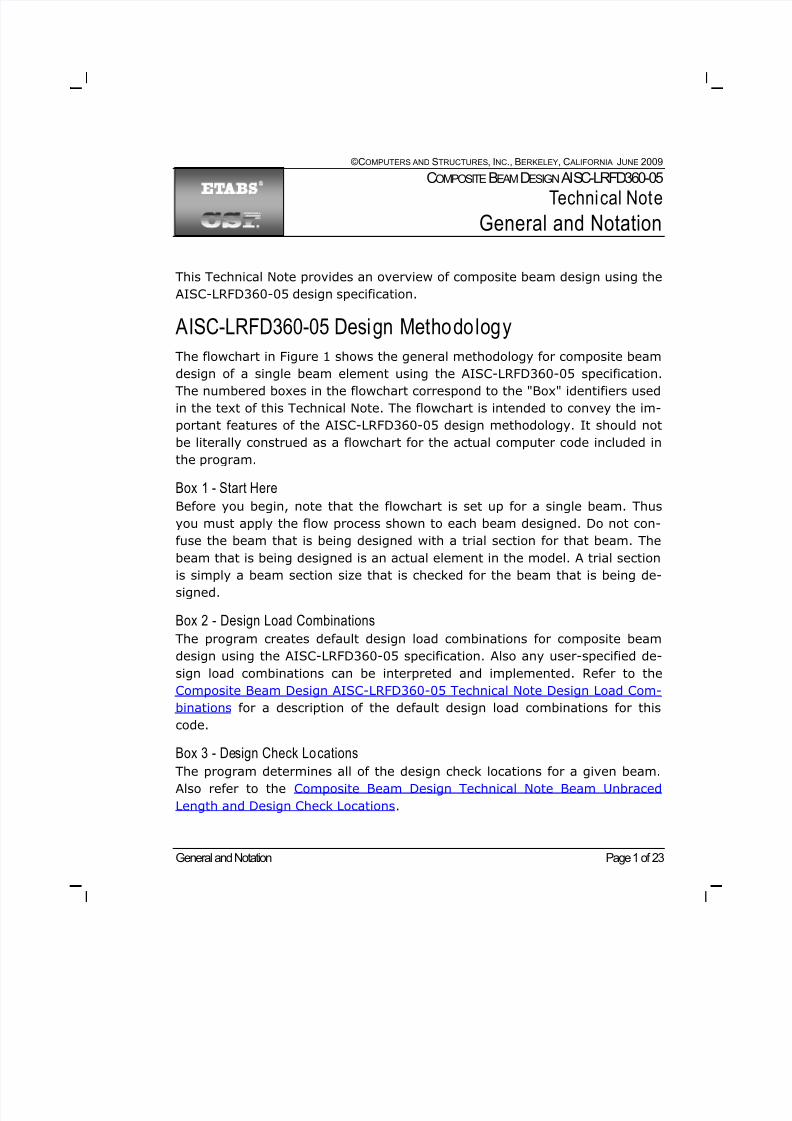
This Technical Note provides an overview of composite beam design using the
AISC-LRFD360-05 design specification.
AISC-LRFD360-05 Design Methodology
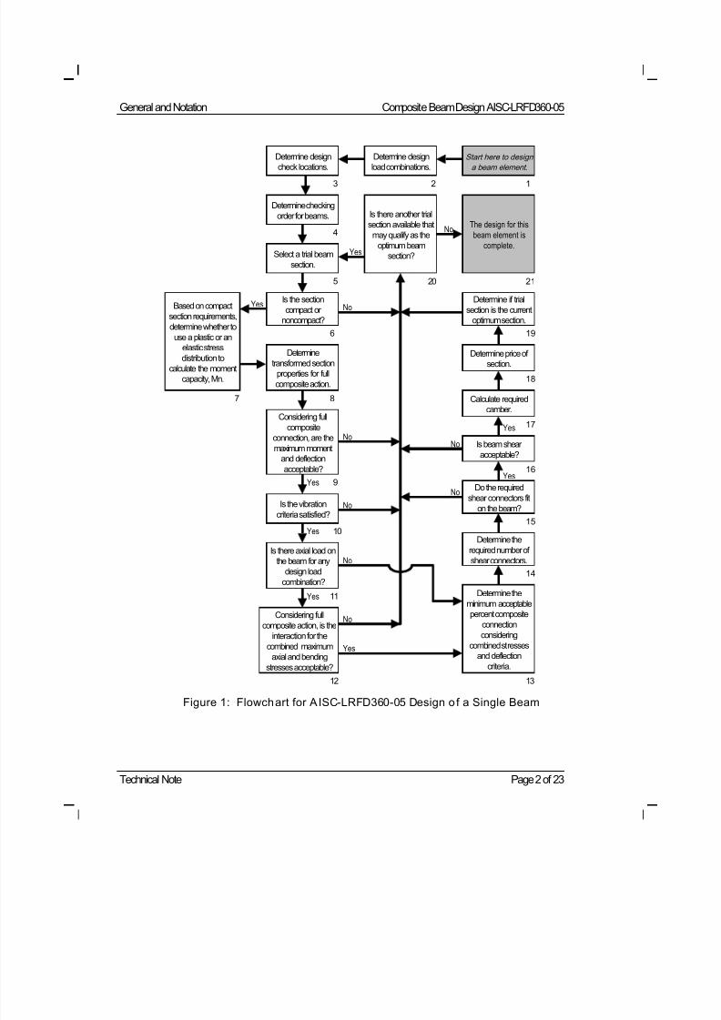
The flowchart in Figure 1 shows the general methodology for composite beam
design of a single beam element using the AISC-LRFD360-05 specification.The numbered boxes in the flowchart correspond to the "Box" identifiers used
in the text of this Technical Note. The flowchart is intended to convey the im-
portant features of the AISC-LRFD360-05 design methodology. It should not
be literally construed as a flowchart for the actual computer code included in
the program.
Box 1 - Start Here
Before you begin, note that the flowchart is set up for a single beam. Thus
you must apply the flow process shown to each beam designed. Do not con-
fuse the beam that is being designed with a trial section for that beam. The
beam that is being designed is an actual element in the model. A trial sectionis simply a beam section size that is checked for the beam that is being de-
signed.
Box 2 - Design Load Combinations
The program creates default design load combinations for composite beam
design using the AISC-LRFD360-05 specification. Also any user-specified de-
sign load combinations can be interpreted and implemented. Refer to the
Composite Beam Design AISC-LRFD360-05 Technical Note Design Load Com-
binations for a description of the default design load combinations for this
code.
Box 3 - Design Check LocationsThe program determines all of the design check locations for a given beam.
Also refer to the Composite Beam Design Technical Note Beam Unbraced
Length and Design Check Locations.
8/21/2019 Composit Beam
http://slidepdf.com/reader/full/composit-beam 2/161
General and Notation Composite Beam Design AISC-LRFD360-05
Technical Note Page 2 of 23
Figure 1: Flowchart for AISC-LRFD360-05 Design o f a Single Beam
No
Start here to design
a beam element.
Determine design
load combinations.
Determine design
check locations.
Determine checking
order for beams.
Select a trial beam
section.
Is the section
compact or
noncompact?
Is there another trial
section available that
may qualify as the
optimum beam
section?Yes
NoThe design for this
beam element is
complete.
Determine
transformed section
properties for full
composite action.
Considering full
composite
connection, are the
maximum moment
and deflection
acceptable?
No
Is the vibration
criteria satisfied?
No
Yes
Yes
Is there axial load on
the beam for any
design load
combination?
Yes
Considering full
composite action, is the
interaction for the
combined maximum
axial and bending
stresses acceptable?
Determine price of
section.
Calculate required
camber.
Is beam shear
acceptable?
Yes
No
Determine if trial
section is the current
optimum section.
Yes
Do the required
shear connectors fit
on the beam?
Determine the
required number of
shear connectors.
Determine the
minimum acceptable
percent composite
connection
considering
combined stresses
and deflection
criteria.
No
No
Yes
123
4
5
6
8
9
10
11
12 13
14
15
16
17
18
19
2120
No
Based on compact
section requirements,
determine whether to
use a plastic or anelastic stress
distribution to
calculate the moment
capacity, Mn.
Yes
7
8/21/2019 Composit Beam
http://slidepdf.com/reader/full/composit-beam 3/161
Composite Beam Design AISC-LRFD360-05 General and Notation
General and Notation Page 3 of 23
Box 4 - Checking Order for Beams
The checking order must be determined for a beam if the beam is assigned anauto select property. The program considers the beams in the auto select list
in the order described in the section entitled “How ETABS Optimizes Design
Groups” in Composite Beam Design Technical Note General Design Informa-
tion.
Box 5 - Trial Beam Section
The program allows the user to select the next trial beam section to be
checked for conformance with the AISC-LRFD360-05 specification and any
additional user-defined criteria. Refer to the section entitled “How ETABS Op-
timizes Design Groups” in Composite Beam Design Technical Note General
Design Information for a description of this selection process.
Box 6 - Compact and Noncompact Requirements
For AISC-LRFD360-05 design of composite beams, the program requires that
the beam section be either compact or noncompact. Slender sections are not
designed. The program checks to make sure the beam is not slender. Refer to
Composite Beam Design AISC-LRFD360-05 Technical Note Compact and Non-
compact Requirements for a description of how the program checks compact
and noncompact requirements.
Box 7 - Stress Distribution Used to Calculate Moment Capacity
The program determines whether to use plastic or elastic stress distribution
when calculating the moment capacity for AISC-LRFD360-05 design. SeeComposite Beam Design AISC-LRFD360-05 Technical Note Compact and Non-
compact Requirements for more information.
Box 8 - Transformed Section Properties
The program computes the transformed section properties of the trial beam
section. If there is only positive bending in the beam, only the transformed
section properties for positive bending are calculated. Similarly, if there is
only negative bending in the beam, only the transformed section properties
for negative bending are calculated. If there is both positive and negative
bending in the beam, transformed section properties for both positive and
negative bending are calculated.
Refer to Composite Beam Design Technical Note Effective Width of the Con-
crete Slab for a description of how the program calculates the effective width
of the concrete slab for the composite beam. Refer to Composite Beam De-
8/21/2019 Composit Beam
http://slidepdf.com/reader/full/composit-beam 4/161
General and Notation Composite Beam Design AISC-LRFD360-05
Technical Note Page 4 of 23
sign AISC-ASD89 Technical Note Transformed Section Moment of Inertia for
description of how the program calculates the transformed section properties.
In AISC-LRFD360-05 design, the transformed section properties are used for
calculating deflection, and they are used when the moment capacity is deter-
mined based on an elastic stress distribution, that is, when the web is non-
compact.
Box 9 - Initial Moment Capacity and Deflection Check
The program checks that the moment capacity of the beam using full compos-
ite connection is greater than or equal to the applied factored moment. It also
checks if the deflection using full composite connection is acceptable. The
main purpose of this check is to quickly eliminate inadequate beam sections.
Refer to Composite Beam Design AISC-LRFD360-05 Technical Note Bending
and Deflection Checks for more information.
Box 10 - Vibration Criteria Check
The program calculates the vibration parameters. If vibration is specified to
be used as one of the tools for selecting the optimum beam size, the program
checks if the vibration parameters satisfy the specified limits. If the vibration
check is satisfied, the design using the current trial section continues; other-
wise, the design for this section is terminated. For more detailed information
on the vibration checks, refer to Composite Beam Design Technical Note
Beam Vibration.
Box 11 - Axial Load
The program checks if axial load exists on the beam for any design load com-
bination. If so, the axial load capacity is determined and the interaction is
subsequently checked, as indicated in box 14. If there is no axial load on the
beam, the axial capacity is not determined and the interaction check (box 14)
is skipped. Refer to Composite Beam Design AISC-LRFD360-05 Technical Note
Compact and Noncompact Requirements for a description of how the program
calculates axial load capacity.
Box 12 - P-M Interaction Check
If there is axial load on the beam, the program checks the P-M interaction
equations. If the interaction check is satisfied, the design using the current
trial section continues; otherwise, the design for this section is terminated.
Refer to Composite Beam Design AISC-LRFD360-05 Technical Note Moment
Capacity for Steel Section Alone for more information.
8/21/2019 Composit Beam
http://slidepdf.com/reader/full/composit-beam 5/161
Composite Beam Design AISC-LRFD360-05 General and Notation
General and Notation Page 5 of 23
Box 13 - Partial Composite Action
A significant amount of design is performed at this point in the process. Theprogram determines the smallest amount of composite connection for which
the beam is adequate. Both flexural checks and deflection checks are made at
this point. In addition, the program considers axial load on the beam if it ex-
ists and is specified to be considered. Flexural checks also are made for the
construction loads.
For more information refer to Composite Beam Design AISC-LRFD360-05
Technical Note Partial Composite Connection with a Plastic Stress Distribution
and Composite Beam Design AISC-LRFD360-05 Technical Note Bending and
Deflection Checks. Also refer to Composite Beam Design AISC-ASD89 Techni-
cal Note Elastic Stresses with Partial Composite Connection.
Box 14 - Required Number of Shear Connectors
The program calculates the required number of shear connectors on the beam
and the distribution of those shear connectors. For more information refer to
Composite Beam Design AISC-LRFD360-05 Technical Note Shear Connectors.
Also refer to Composite Beam Design Technical Note Distribution of Shear
Studs on a Composite Beam and Composite Beam Design Technical Note The
Number of Shear Studs that Fit in a Composite Beam Segment. Finally refer
to Composite Beam Design Technical Note Effective Width of the Concrete
Slab for limitations associated with composite beams and formed metal deck.
Box 15 - Checking i f Shear Connectors Fit on the BeamThe program checks if the number of shear connectors calculated (box 14)
actually fit on the beam. For more information refer to Composite Beam De-
sign Technical Note Number of Shear Studs that Fit in a Composite Beam
Segment. If the connectors fit on the beam, the design using the current trial
section continues; otherwise, the design for this section is terminated.
Box 16 - Beam Shear
The program checks the beam shear for the reactions at each end of the
beam. See Composite Beam Design AISC-LRFD360-05 Technical Note Beam
Shear Capacity for more information. If the beam shear check is satisfied, the
design using the current trial section continues; otherwise, the design for thissection is terminated.
8/21/2019 Composit Beam
http://slidepdf.com/reader/full/composit-beam 6/161
General and Notation Composite Beam Design AISC-LRFD360-05
Technical Note Page 6 of 23
Box 17 - Camber
The program determines the camber for the beam, if it is specified to havecamber. Refer to Composite Beam Design Technical Note Beam Deflection and
Camber for more information.
Box 18 - Section Price
Determination of price of section applies only when price has been specified
by the user as the method of selecting the optimum section. In such cases,
the program determines the price of the current beam. Refer to “Using Price
to Select Optimum Beam Sections” in Composite Beam Design Technical Note
General Design Information for more information.
Box 19 - Check if a Section is the Current Optimum Section
This check applies only if price has been specified as the method of selectingthe optimum section. The program checks if the price of the current trial
beam is less than that of any other beam that satisfied the design criteria. If
so, the current beam section becomes the current optimum beam section.
Refer to “Using Price to Select Optimum Beam Sections” in Composite Beam
Design Technical Note General Design Information for more information
If the optimum beam size is to be selected by weight, this check becomes ir-
relevant because the beams are checked in order from the lightest to the
heaviest beams and thus the first beam found to work is the optimum beam.
Box 20 - Check for Possible Addit ional Optimum SectionsThis check applies only if the beam has been assigned an auto selection prop-
erty. The program checks if another section in the auto selection list might
qualify as the optimum beam section. Refer to “How ETABS Optimizes Design
Groups” in Composite Beam Design Technical Note General Design Informa-
tion for more information.
Box 21 - Design Complete
At this point, the design for this particular beam element is complete. If the
beam has been assigned an auto selection property, the current optimum
section, assuming one has been found, is the optimum section for the beam.
The program will indicate if no beam with an optimum section is included in
the auto selection list.
8/21/2019 Composit Beam
http://slidepdf.com/reader/full/composit-beam 7/161
Composite Beam Design AISC-LRFD360-05 General and Notation
General and Notation Page 7 of 23
If the beam is assigned a regular, non-auto selection property, the design for
that beam property will be provided or the beam will be indicated to be in-adequate.
There are some additional aspects included in the composite beam design
module that are not directly addressed in the flowchart shown in Figure 1.
Those include designing beams in groups and designing beams with partial
length cover plates.
For more information on the design by group feature, refer to the section
"How the Program Optimizes Design Groups" in Composite Beam Design
Technical Note General Design Information. The extension of the methodology
described in Part 3 to designing by groups is relatively simple and is assumed
to be apparent to the reader.
When a beam has a partial length cover plate, the program checks not only
the design at the point of the maximum moment (box 8 of Figure 1), but also
the design at the point of the largest moment where the cover plate does not
exist.
Notation
Abare Area of the steel beam (plus coverplate) alone, in2.
Ac Area of concrete within slab effective width that is above the
elastic neutral axis (ENA) for full composite action, in2. For
beams with metal deck ribs running perpendicular to the beam
span, only the concrete above the metal deck and above the
ENA is included. For beams with metal deck ribs running paral-
lel to the beam span, the concrete above the metal deck and
the concrete in the deck ribs are included if it is above the
ENA. This value may be different on the left and right sides of
the beam.
Af Area of compression flange, in2.
Ag Gross area of steel member, in2
.
8/21/2019 Composit Beam
http://slidepdf.com/reader/full/composit-beam 8/161
General and Notation Composite Beam Design AISC-LRFD360-05
Technical Note Page 8 of 23
As Area of rolled steel section, or the total area (excluding cover
plate) of a user-defined steel section, in
2
. Note that the totalarea of a user-defined steel section is found by summing the
area of the top flange, web, and bottom flange.
ASb Initial displacement amplitude of a single beam resulting from
a heel drop impact, in.
Asc Cross-sectional area of a shear stud connector, in2.
Atr Area of an element of the composite steel beam section, in2.
Aw Area of the web equal to the overall depth d times the web
thickness t w , in
2
.
B1 Moment magnifier, unitless.
C b Bending coefficient dependent on moment gradient, unitless.
C bot Cope depth at bottom of beam, in.
C C 1 Compressive force in the concrete slab above the metal deck,
kips. If no metal deck exists, this is the compressive force in
the slab.
C C 2 Compressive force in concrete that is in the metal deck ribs,
kips. This force occurs only when the metal deck ribs are ori-
ented parallel to the steel beam, and the plastic neutral axis is
below the top of the metal deck.
C FT Compressive force in the top flange of the steel beam, kips.
This force occurs only when the plastic neutral axis is below
the top of the beam.
C KT Compressive force in the top fillets of a rolled steel beam,
kips. This force occurs only when the plastic neutral axis is be-
low the bottom of the top flange of the beam.
C R Compressive force in the slab rebar, kips. This force occurs
only when the plastic neutral axis is below the rebar, and the
user has specified that the rebar is to be considered.
8/21/2019 Composit Beam
http://slidepdf.com/reader/full/composit-beam 9/161
Composite Beam Design AISC-LRFD360-05 General and Notation
General and Notation Page 9 of 23
C top Cope depth at top of beam, in.
C w Warping constant for a section, in6.
C Web Compressive force in the steel beam web, kips. This force oc-
curs only when the plastic neutral axis is within the beam web.
D Damping ratio, percent critical damping inherent in the floor
system, unitless.
E c Modulus of elasticity of concrete slab, ksi. Note that this could
be different on the left and right sides of the beam. Also note
that this is different for stress calculations and deflection cal-
culations.
E s Modulus of elasticity of steel, ksi.
F cr Critical stress for columns in compression, ksi.
F L Smaller of (F yf - F r ) or F yw , ksi.
F r Compressive residual stress in flange, ksi. Taken as 10 kips
per square inch for rolled shapes and 16.5 kips per square
inch for welded shapes.
F u Minimum specified tensile strength of structural steel or shear
stud, ksi.
F y Minimum specified yield stress of structural steel, ksi.
F ycp Minimum specified yield stress of cover plate, ksi.
F yf-bot Minimum specified yield stress of steel in beam bottom flange,
ksi.
F yf -top Minimum specified yield stress of steel in beam top flange, ksi.
F yw Minimum specified yield stress of steel in beam web, ksi.
G Shear modulus of elasticity of steel, ksi.
H s Length of shear stud connector after welding, in.
8/21/2019 Composit Beam
http://slidepdf.com/reader/full/composit-beam 10/161
General and Notation Composite Beam Design AISC-LRFD360-05
Technical Note Page 10 of 23
I eff Effective moment of inertia of a partially composite beam, in4.
I O Moment of inertia of an element of the composite steel beam
section taken about its own center of gravity, in4.
I s Moment of inertia of the steel beam alone plus cover plate if
applicable, in4.
I tr Transformed section moment of inertia about elastic neutral
axis of the composite beam, in4.
I x , I y Moment of inertia about the x and y axes of the beam, respec-
tively, in4.
I yc Moment of inertia of compression flange about the y axis, or if
there is both positive and negative bending in the beam, the
smaller moment of the two flanges, in4.
J Torsional constant for a section, in4.
K Effective length factor for prismatic member, unitless.
K f A unitless coefficient typically equal to 1.57 unless the beam is
the overhanging portion of a cantilever with a backspan, in
which case K f is as defined in Figure 1 of Composite Beam De-
sign Technical Note Beam Vibration, or the beam is a cantile-
ver that is fully fixed at one end and free at the other end, in
which case K f is 0.56.
L Center-of-support to center-of-support length of the beam, in.
Lb Laterally unbraced length of beam; length between points that
are braced against lateral displacement of the compression
flange or braced against twist of the cross section, in.
Lc Limiting unbraced length for determining allowable bending
stress, in.
8/21/2019 Composit Beam
http://slidepdf.com/reader/full/composit-beam 11/161
Composite Beam Design AISC-LRFD360-05 General and Notation
General and Notation Page 11 of 23
LCBS Length of a composite beam segment, in. A composite beam
segment spans between any of the following: (1) physical endof the beam top flange; (2) another beam framing into the
beam being considered; (3) physical end of concrete slab. Fig-
ure 1 Composite Beam Design Technical Note Distribution of
Shear Studs on a Composite Beam illustrates some typical
cases for LCBS.
Lcsc Length of channel shear connector, in.
L p Limiting laterally unbraced length of beam for full plastic bend-
ing capacity, uniform moment case (C b = 1.0), in.
Lr Limiting laterally unbraced length of beam for inelastic lateral-torsional buckling, in.
Ls Distance between two points used when the program is calcu-
lating the maximum number of shear studs that can fit be-
tween those points, in. If the deck span is oriented parallel to
the beam span and at least one of the points is at the end of
the beam, then Ls is taken as the distance between the two
points minus 3 inches.
L1 Distance from point of maximum moment to the closest point
of zero moment or physical end of beam top flange, or physi-
cal end of concrete slab, in.
L2 Distance from point of maximum moment to the nearest point
of zero moment or physical end of beam top flange, or physi-
cal end of concrete slab measured on the other side of the
point of maximum moment from the distance L1, in.
8/21/2019 Composit Beam
http://slidepdf.com/reader/full/composit-beam 12/161
General and Notation Composite Beam Design AISC-LRFD360-05
Technical Note Page 12 of 23
L3 Distance from point load to the point of zero moment, physical
end of beam top flange, or physical end of concrete slabmeasured on the appropriate side of the point load, in. If the
point load is located on the left side of the point of maximum
moment, the distance is measured from the point load toward
the left end of the beam. If the point load is located on the
right side of the point of maximum moment, the distance is
measured toward the right end of the beam.
M Moment, kip-in.
M A Absolute value of moment at the quarter point of the unbraced
beam segment, kip-in.
M B Absolute value of moment at the centerline of the unbraced
beam segment, kip-in.
M C Absolute value of moment at the three-quarter point of the
unbraced beam segment, kip-in.
M cr Elastic buckling moment, kip-in.
M max Maximum positive moment for a beam, kip-in.
M n Nominal flexural strength, kip-in.
M p Plastic bending moment, kip-in.
M pt load Moment at the location of a point load, kip-in.
M r Limiting buckling moment, M cr , when = r and C b = 1.0, kip-
in.
M u Required flexural strength, kip-in.
MPF conc Maximum possible force that can be developed in the concrete
slab, and rebar in slab, if applicable, kips.
MPF steel Maximum possible force that can be developed in the steel
section, and cover plate, if applicable, kips.
8/21/2019 Composit Beam
http://slidepdf.com/reader/full/composit-beam 13/161
Composite Beam Design AISC-LRFD360-05 General and Notation
General and Notation Page 13 of 23
N CBS The number of uniformly distributed shear connectors the pro-
gram specifies for a composite beam segment, unitless.
N eff The effective number of beams resisting the heel drop impact,
unitless.
N r Number of shear stud connectors in one rib at a beam inter-
section; not to exceed three in computations, although more
than three studs may be installed, unitless.
N 1 Required number of shear connectors between the point of
maximum moment and an adjacent point of zero moment (or
end of slab), unitless.
N 2 Required number of shear connectors between a point load
and a point of zero moment (or end of slab), unitless.
NR Available number of metal deck ribs between two points,
unitless.
NSmax Maximum number of shear stud connectors between two
points a distance of Ls apart, unitless.
P Axial load, kips.
P e Euler buckling load, kips.
P n Nominal axial strength (tension or compression), kips.
P nc Nominal compressive axial strength, kips.
P nt Nominal tensile axial strength, kips.
P O Heel drop force, kips. This force is taken as 0.6 kips.
P u Required axial strength (tension or compression), kips.
P y Axial compressive yield strength , kips.
PCC Percent composite connection, unitless. The exact formula for
this term is code dependent.
8/21/2019 Composit Beam
http://slidepdf.com/reader/full/composit-beam 14/161
General and Notation Composite Beam Design AISC-LRFD360-05
Technical Note Page 14 of 23
Qn Nominal strength of one shear connector (shear stud or chan-
nel), kips.
R Wiss-Parmelee rating factor, unitless.
RF Reduction factor for horizontal shear capacity of shear connec-
tors, unitless.
RSmax Maximum number of rows of shear stud connectors that can fit
between two points a distance of Ls apart, unitless.
Sed Minimum edge distance from midheight of a metal deck rib to
the center of a shear stud, in. For an example see paragraph
1b of the section Solid Slab or Deck Ribs Oriented Parallel toBeam Span in Composite Beam Design Technical Note Number
of Shear Studs that Fit in a Composite Beam Segment. The
default value is 1 inch. You can change this in the preferences
and the overwrites.
Seff Effective section modulus of a partially composite beam with
respect to the extreme tension fiber of the steel beam section
(including cover plate), in3.
Sr Center-to-center spacing of metal deck ribs, in.
Ss Section modulus of the steel beam alone, plus cover plate ifapplicable, with respect to the tension flange, in3.
St -eff The section modulus for the partial composite section with re-
spect to the top of the equivalent transformed section, in3.
Stop Section modulus for the fully composite uncracked trans-
formed section with respect to the extreme compression fiber,
in3.
Str Section modulus for the fully composite uncracked trans-
formed section with respect to the extreme tension fiber of the
steel beam section (including cover plate), in3.
S x , Sy Section modulus about the x and y axes of the beam, respec-
tively, in3.
8/21/2019 Composit Beam
http://slidepdf.com/reader/full/composit-beam 15/161
Composite Beam Design AISC-LRFD360-05 General and Notation
General and Notation Page 15 of 23
S xc Section modulus about the x axis of the outside fiber of the
compression flange, in
3
.
S xt Section modulus about the x axis of the outside fiber of the
tension flange, in3.
SRmax Maximum number of shear stud connectors that can fit in one
row across the top flange of a composite beam, unitless.
T B Tensile force in a composite rolled steel beam when the plastic
neutral axis is above the top of the beam, kips.
T CP Tensile force in the cover plate, kips.
T FB Tensile force in the bottom flange of a steel beam, kips.
T FT Tensile force in the top flange of a steel beam, kips.
T KB Tensile force in the bottom fillets of a rolled steel beam, kips.
T KT Tensile force in the top fillets of a rolled steel beam, kips.
T Web Tensile force in the web of a steel beam, kips.
V Shear force, kips.
V n Nominal shear strength, kips.
V u Required shear strength, kips.
W Total load supported by the beam, kips. The user specifies a
load combination that the program uses to determine this
weight.
X 1 Beam buckling factor defined by AISC-LRFD360-05 equation
F1-8.
X 2 Beam buckling factor defined by AISC-LRFD360-05 equation
F1-9.
Z Plastic section modulus of the steel beam alone plus cover
plate if applicable, in3.
8/21/2019 Composit Beam
http://slidepdf.com/reader/full/composit-beam 16/161
General and Notation Composite Beam Design AISC-LRFD360-05
Technical Note Page 16 of 23
Z x , Z y Plastic section modulus about the x and y axes of the beam
respectively, in
3
.
a Clear distance between transverse stiffeners, in.
ar For a user-defined section, ratio of web area to flange area,
but not more than 10, unitless.
a1 Distance from top of concrete to bottom of effective concrete
for partial composite connection when bottom of effective con-
crete is within the slab above the metal deck (or there is a
solid slab with no metal deck), in.
a2 Distance from top of metal deck to bottom of effective con-crete for partial composite connection when bottom of effec-
tive concrete is within the height of the metal deck, in.
a3 Distance from top of metal deck to elastic neutral axis when
elastic neutral axis is located in slab above metal deck, in.
a4 Distance from top of concrete slab to elastic neutral axis when
elastic neutral axis is located in slab above metal deck, in.
a5 Distance from bottom of metal deck to elastic neutral axis
when elastic neutral axis is located within height of metal
deck, in.
a6 Distance from top of metal deck to elastic neutral axis when
elastic neutral axis is located within height of metal deck, in.
b Width, in.
bcp Width of steel cover plate, in.
beff Effective width of concrete flange of composite beam, in.
bf Width of flange of a rolled steel beam, in.
bf -bot Width of bottom flange of a user-defined steel beam, in.
bf -top Width of top flange of a user-defined steel beam, in.
8/21/2019 Composit Beam
http://slidepdf.com/reader/full/composit-beam 17/161
Composite Beam Design AISC-LRFD360-05 General and Notation
General and Notation Page 17 of 23
d Depth of steel beam from outside face of top flange to outside
face of bottom flange, in.
d avg Average depth of concrete slab, including the concrete in the
metal deck ribs, in.
d sc Diameter of a shear stud connector, in.
f First natural frequency of the beam in cycles per second.
f 'c Specified compressive strength of concrete, ksi.
g Acceleration of gravity, in/seconds2.
h Clear distance between flanges less the fillet or corner radiusat each flange for rolled shapes and clear distance between
flanges for other shapes, in.
hc For rolled shapes, twice the distance from the beam centroid
to the inside face of the compression flange less the fillet or
corner radius. In a user-defined section, twice the distance
from the centroid of the steel beam alone, not including the
cover plate even if it exists, to the inside face of the compres-
sion flange, in.
hr Height of metal deck rib, in.
k Distance from outer face of a rolled beam flange to the web
toe of a fillet, in.
k c Unitless factor used in AISC-LRFD360-05 Table B5.1, 0.35 kc
0.76.
k depth Distance from inner face of a rolled beam flange to the web
toe of a fillet, in.
k width Width of idealized fillet of rolled beam section, in.
l Controlling laterally unbraced length of a member, in.
8/21/2019 Composit Beam
http://slidepdf.com/reader/full/composit-beam 18/161
General and Notation Composite Beam Design AISC-LRFD360-05
Technical Note Page 18 of 23
l 22, l 33 Laterally unbraced length of a member for buckling about the
local 2 and 3 axes of the beam respectively, in.
l x , l y Laterally unbraced length of a member for buckling about the
x and y axes of the beam respectively, in.
m For a user-defined section, ratio of web yield stress to flange
yield stress, unitless.
r Governing radius of gyration, in.
r d Distance from top of beam flange to bottom of metal deck, in.
r 22, r 33 Radius of gyration about the local 2 and 3 axes of the beam
respectively, in.
r T Radius of gyration of a section comprising the compression
flange plus one-third of the compression web area taken about
an axis in the plane of the web, in.
r x , r y Radius of gyration about the x and y axes of the beam respec-
tively, in.
r yc Radius of gyration of the compression flange about the y-axis,
in.
sb Beam spacing, in.
t Thickness, in.
t c Thickness of concrete slab, in. If there is metal deck,this is the
thickness of the concrete slab above the metal deck.
t cp Thickness of cover plate, in.
t f Thickness of steel beam flange, in.
t f -bot Thickness of bottom flange of a user-defined steel beam, in.
t f -top Thickness of top flange of a user-defined steel beam, in.
8/21/2019 Composit Beam
http://slidepdf.com/reader/full/composit-beam 19/161
Composite Beam Design AISC-LRFD360-05 General and Notation
General and Notation Page 19 of 23
t O Time to the maximum initial displacement of a single beam
resulting from a heel drop impact, seconds.
t w Thickness of web of user-defined steel beam, in.
w a Additional metal deck rib width, in. This term is used to specify
metal deck ribs that are split over the beam. The width w a is
added to the width w r when determining the width of deck rib
available for shear studs.
w c Unit weight per volume of concrete, pounds/feet3.
w d Unit weight per area of metal deck, ksi.
wr Average width of metal deck rib, in.
x 1 The assumed gap distance from the supporting beam or col-
umn flange to the end of the beam flange, in. The default
value for this length is 0.5 inch.
y Distance from the bottom of the bottom flange of the steel
beam section to the elastic neutral axis of the fully composite
beam, in.
y bare The distance from the bottom of the bottom flange of the steel
beam to the neutral axis of the noncomposite steel beam plus
cover plate if applicable, in.
y e The distance from the elastic neutral axis of the bare steel
beam alone (plus cover plate, if applicable) to the elastic neu-
tral axis of the fully composite beam, in.
y eff The distance from the bottom of the bottom flange of the steel
beam to the neutral axis of the partially composite beam, in.
y 1 Distance from the bottom of the bottom flange of the steel
beam section to the centroid of an element of the composite
beam section, in.
8/21/2019 Composit Beam
http://slidepdf.com/reader/full/composit-beam 20/161
General and Notation Composite Beam Design AISC-LRFD360-05
Technical Note Page 20 of 23
y 2 Distance from the top of the top flange of the steel beam sec-
tion to the plastic neutral axis when the plastic neutral axis iswithin the beam top flange, in.
y 3 Distance from the bottom of the top flange of a rolled steel
beam section to the plastic neutral axis when the plastic neu-
tral axis is within the fillets, in.
y 4 For a rolled steel beam, the distance from the bottom of the
top fillet to the plastic neutral axis when the plastic neutral
axis is within the beam web, in. For a user-defined steel beam,
the distance from the bottom of the top flange to the plastic
neutral axis when the plastic neutral axis is within the beam
web, in.
y p Distance from the plastic neutral axis of composite section to
the bottom of the beam bottom flange (not cover plate), in.
z Distance from the elastic neutral axis of the steel beam (plus
cover plate, if it exists) alone to the top of the concrete slab,
in. Note that this distance may be different on the left and
right sides of the beam.
z p Distance from the plastic neutral axis of composite section to
the top of the concrete slab, in. Note that this distance may be
different on the left and right sides of the beam.
A Sum of the areas of all of the elements of the steel beam sec-
tion, in2.
Atr Sum of the areas of all of the elements of the composite steel
beam section, in2.
( Atr y 1) Sum of the product Atr times y 1 for all of the elements of the
composite steel beam section, in3.
( Ay 1) Sum of the product A times y 1 for all of the elements of the
steel beam section, in3.
8/21/2019 Composit Beam
http://slidepdf.com/reader/full/composit-beam 21/161
Composite Beam Design AISC-LRFD360-05 General and Notation
General and Notation Page 21 of 23
( Ay 12) Sum of the product A times y 1
2 for all of the elements of the
steel beam section, in
4
.
( Atr y 12)= Sum of the product Atr times y 1
2 for all of the elements of the
composite steel beam section, in4.
I O Sum of the moments of inertia of each element of the compos-
ite steel beam section taken about the center of gravity of the
element, in4.
Qn Sum of nominal strength of shear connectors (shear stud or
channel) between point considered and point of zero moment,
kips.
Qn-pcc Required nominal strength of shear connectors (shear stud or
channel) between point considered and point of zero moment
for partial composite connection percentage, PCC , kips.
Qn-100 Required nominal strength of shear connectors (shear stud or
channel) between point considered and point of zero moment
for full (100%) composite action, kips.
Unitless factor used in calculating number of shear studs be-
tween a point load and a point of zero moment equal to Str /Ss
for full composite connection and Seff /Ss for partial composite
connection.
Resistance factor, unitless.
b Resistance factor for bending in a noncomposite beam,
unitless. The default value is 0.9.
bcc Resistance factor applied to concrete for bending in a compos-
ite section, unitless. Note that this is a resistance factor that is
not defined by AISC. It is included by CSI to give the user
more control over the strength of the composite section. The
default value is 1.0.
8/21/2019 Composit Beam
http://slidepdf.com/reader/full/composit-beam 22/161
General and Notation Composite Beam Design AISC-LRFD360-05
Technical Note Page 22 of 23
bcne Resistance factor for negative bending in a composite beam
when M n is determined from an elastic stress distribution,unitless. The default value is 0.9.
bcnp Resistance factor for negative bending in a composite beam
when M n is determined from a plastic stress distribution,
unitless. The default value is 0.9.
bcpe Resistance factor for positive bending in a composite beam
when M n is determined from an elastic stress distribution,
unitless. The default value is 0.9.
bcpp Resistance factor for positive bending in a composite beam
when M n is determined from a plastic stress distribution,unitless. The default value is 0.90.
bcs Resistance factor applied to steel for bending in a composite
section, unitless. Note that this is a resistance factor that is
not defined by AISC. It is included by CSI to give the user
more control over the strength of the composite section. The
default value is 1.0.
bs Resistance factor for strength of shear studs, unitless. Note
that this is a resistance factor that is not defined by AISC. It is
included by CSI to give the user more control over the
strength of the composite section. The default value is 1.0.
c Resistance factor for axial compression, unitless. The default
value is 0.9.
t Resistance factor for axial tension, unitless. The default value
is 0.9.
v Resistance factor for beam shear, unitless. The default value is
0.9.
8/21/2019 Composit Beam
http://slidepdf.com/reader/full/composit-beam 23/161
Composite Beam Design AISC-LRFD360-05 General and Notation
General and Notation Page 23 of 23
Controlling slenderness parameter, unitless. It is the minor
axis slenderness ratio Lb /ry for lateral-torsional buckling. It isthe flange width-thickness ratio b/t as defined in AISC LRFD
Manual Specification section B5.1 for flange local buckling. It is
the web depth-thickness ratio h/tw as defined in AISC LRFD
Manual Specification section B5.1 for web local buckling.
c Column slenderness parameter, unitless.
p Limiting slenderness parameter for a compact element, largest
value of for which Mn = Mp, unitless.
r Limiting slenderness parameter for a noncompact element,
largest value of for which buckling is inelastic, unitless.
8/21/2019 Composit Beam
http://slidepdf.com/reader/full/composit-beam 24/161
Preferences Page 1 of 9
©COMPUTERS AND STRUCTURES, INC., BERKELEY, C ALIFORNIA JUNE 2009
COMPOSITEBEAMDESIGN AISC-LRFD360-05
Technical Note
Preferences
General
The composite beam design preferences are basic assignments that apply to
all composite beams. Use the Options menu > Preferences > Composite
Beam Design command to access the Preferences form; the form can be
used to view and revise the composite beam design preferences. The Com-
posite Beam Design Preferences form has five separate tabs: Factors, Beam,Deflection, Vibration, and Price.
Default values are provided for all composite beam design preferences. Thus,
it is not necessary to specify or change any of the preferences. However, the
preference items should be reviewed to make sure they are acceptable.
Using the Preferences Form
To view preferences, select the Options menu > Preferences > Composite
Beam Design. The Preferences form will display. When the Preferences form
displays, review and, if necessary, change the specified design code in the
drop-down box near the bottom of the form.
Click on the desired tab: Factors, Beam, Deflection, Vibration or Price. The
preference options included under each of the tabs are displayed in a two-
column spreadsheet. The left column of the spreadsheet displays the prefer-
ence item name. The right column of the spreadsheet displays the preference
item value.
To change a preference item, left click the desired preference item in either
the left or right column of the spreadsheet. This activates a drop-down box or
highlights the current preference value. If the drop-down box appears, select
a new value. If the cell is highlighted, type in the desired value. The prefer-ence value will update accordingly.
8/21/2019 Composit Beam
http://slidepdf.com/reader/full/composit-beam 25/161
Preferences Composite Beam Design AISC-LRFD360-05
Technical Note Page 2 of 9
When the preference item is clicked in either column, a short description of
that item displays in the large text box just below the list of items. This de-scription explains the purpose of each preference item without referring to the
documentation.
To set all of the composite beam preference items on a particular tab to their
default values, click on that tab to view it and then click the Reset Tab but-
ton. This button resets the preference values on the currently selected tab.
To set all of the composite beam preference items on all tabs to their default
values, click the Reset All button. This button immediately resets all of the
composite beam preference items.
I m p o r t a n t n o t e a b o u t r e s e t t i n g p r e f er e n c es : The defaults for the prefer-ence items are built into the program. The composite beam preference values
that were in a .edb file used to initialize a model may be different from the
built-in default values. Clicking a reset button resets the preference values to
built-in values, not to the values that were in the .edb file used to initialize
the model.
Preferences
For purposes of explanation in this Technical Note, the preference items are
presented in tables. The column headings in these tables are described as fol-
lows:
Item: The name of the preference item as it appears in the cells at the
left side of the Preferences form.
Possible Values: The possible values that the associated preference
item can have.
Default Value: The built-in default value that the program assumes for
the associated preference item.
Description: A description of the associated preference item.
8/21/2019 Composit Beam
http://slidepdf.com/reader/full/composit-beam 26/161
Composite Beam Design AISC-LRFD360-05 Preferences
Preferences Page 3 of 9
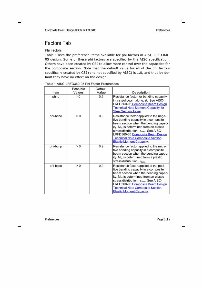
Factors TabPhi Factors
Table 1 lists the preference items available for phi factors in AISC-LRFD360-
05 design. Some of these phi factors are specified by the AISC specification.
Others have been created by CSI to allow more control over the capacities for
the composite section. Note that the default value for all of the phi factors
specifically created by CSI (and not specified by AISC) is 1.0, and thus by de-
fault they have no effect on the design.
Table 1 AISC-LRFD360-05 Phi Factor Preferences
ItemPossibleValues
DefaultValue Description
phi-b >0 0.9 Resistance factor for bending capacityin a steel beam alone, b. See AISC-LRFD360-05 Composite Beam DesignTechnical Note Moment Capacity forSteel Section Alone.
phi-bcne > 0 0.9 Resistance factor applied to the nega-tive bending capacity in a compositebeam section when the bending capac-ity, Mn, is determined from an elastic stress distribution, bcne. See AISC-LRFD360-05 Composite Beam DesignTechnical Note Composite SectionElastic Moment Capacity.
phi-bcnp > 0 0.9 Resistance factor applied to the nega-tive bending capacity in a compositebeam section when the bending capac-ity, Mn, is determined from a plastic stress distribution, bcnp.
phi-bcpe > 0 0.9 Resistance factor applied to the posi-tive bending capacity in a compositebeam section when the bending capac-ity, Mn, is determined from an elastic stress distribution, bcne. See AISC-LRFD360-05 Composite Beam DesignTechnical Note Composite Section
Elastic Moment Capacity.
8/21/2019 Composit Beam
http://slidepdf.com/reader/full/composit-beam 27/161
Preferences Composite Beam Design AISC-LRFD360-05
Technical Note Page 4 of 9
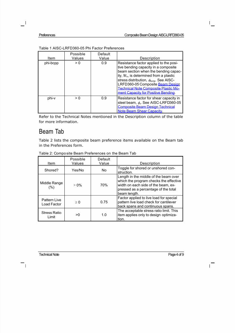
Table 1 AISC-LRFD360-05 Phi Factor Preferences
Item PossibleValues DefaultValue Description
phi-bcpp > 0 0.9 Resistance factor applied to the posi-tive bending capacity in a compositebeam section when the bending capac-ity, Mn, is determined from a plastic stress distribution, bcnp. See AISC-LRFD360-05 Composite Beam DesignTechnical Note Composite Plastic Mo-ment Capacity for Positive Bending.
phi-v > 0 0.9 Resistance factor for shear capacity insteel beam, v. See AISC-LRFD360-05Composite Beam Design Technical
Note Beam Shear Capacity.Refer to the Technical Notes mentioned in the Description column of the table
for more information.
Beam Tab
Table 2 lists the composite beam preference items available on the Beam tab
in the Preferences form.
Table 2: Composite Beam Preferences on the Beam Tab
ItemPossibleValues
DefaultValue Description
Shored? Yes/No No Toggle for shored or unshored con-struction.
Middle Range(%)
0% 70%
Length in the middle of the beam overwhich the program checks the effectivewidth on each side of the beam, ex-pressed as a percentage of the totalbeam length.
Pattern LiveLoad Factor
0 0.75Factor applied to live load for specialpattern live load check for cantileverback spans and continuous spans.
Stress RatioLimit
>0 1.0The acceptable stress ratio limit. Thisitem applies only to design optimiza-tion.
8/21/2019 Composit Beam
http://slidepdf.com/reader/full/composit-beam 28/161
Composite Beam Design AISC-LRFD360-05 Preferences
Preferences Page 5 of 9
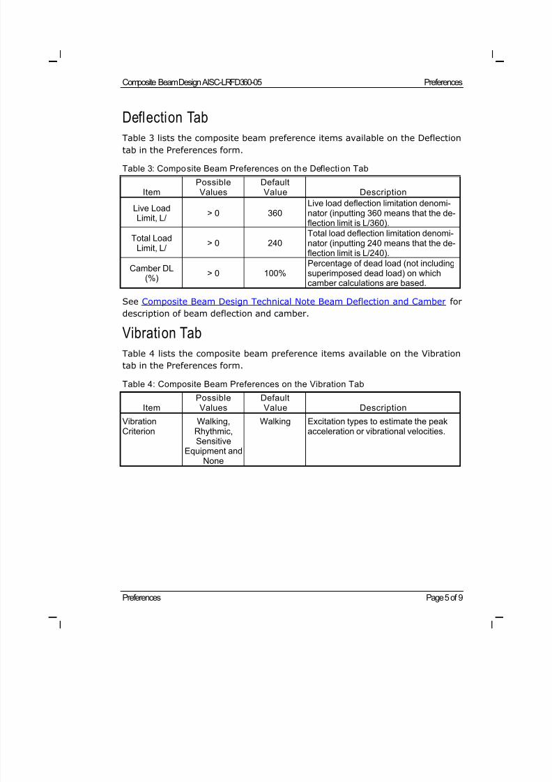
Deflection Tab
Table 3 lists the composite beam preference items available on the Deflection
tab in the Preferences form.
Table 3: Composite Beam Preferences on the Deflection Tab
ItemPossibleValues
DefaultValue Description
Live LoadLimit, L/
> 0 360Live load deflection limitation denomi-nator (inputting 360 means that the de-flection limit is L/360).
Total LoadLimit, L/
> 0 240Total load deflection limitation denomi-nator (inputting 240 means that the de-flection limit is L/240).
Camber DL(%)
> 0 100%Percentage of dead load (not includingsuperimposed dead load) on whichcamber calculations are based.
See Composite Beam Design Technical Note Beam Deflection and Camber for
description of beam deflection and camber.
Vibration Tab
Table 4 lists the composite beam preference items available on the Vibration
tab in the Preferences form.
Table 4: Composite Beam Preferences on the Vibration Tab
ItemPossibleValues
DefaultValue Description
VibrationCriterion
Walking,Rhythmic,Sensitive
Equipment andNone
Walking Excitation types to estimate the peakacceleration or vibrational velocities.
8/21/2019 Composit Beam
http://slidepdf.com/reader/full/composit-beam 29/161
Preferences Composite Beam Design AISC-LRFD360-05
Technical Note Page 6 of 9
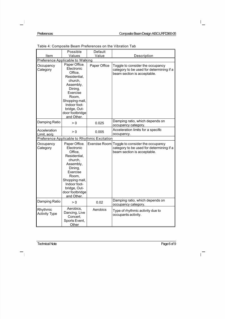
Table 4: Composite Beam Preferences on the Vibration Tab
Item PossibleValues DefaultValue Description
Preference Applicable to Walking
OccupancyCategory
Paper Office,Electronic
Office,Residential,
church, Assembly,
Dining,ExerciseRoom,
Shopping mall,Indoor foot-bridge, Out-
door footbridgeand Other.
Paper Office Toggle to consider the occupancycategory to be used for determining if abeam section is acceptable.
Damping Ratio > 0 0.025Damping ratio, which depends onoccupancy category.
AccelerationLimit, ao/g
> 0 0.005 Acceleration limits for a specificoccupancy.
Preference Applicable to Rhythmic Excitation
OccupancyCategory
Paper Office,Electronic
Office,Residential,
church, Assembly,
Dining,ExerciseRoom,
Shopping mall,Indoor foot-bridge, Out-
door footbridgeand Other.
Exercise Room Toggle to consider the occupancycategory to be used for determining if abeam section is acceptable.
Damping Ratio > 0 0.02Damping ratio, which depends onoccupancy category.
Rhythmic
Activity Type
Aerobics,
Dancing, LiveConcert,Sports Event,
Other
Aerobics Type of rhythmic activity due to
occupants activity.
8/21/2019 Composit Beam
http://slidepdf.com/reader/full/composit-beam 30/161
Composite Beam Design AISC-LRFD360-05 Preferences
Preferences Page 7 of 9
Table 4: Composite Beam Preferences on the Vibration Tab
Item PossibleValues DefaultValue Description
AffectedOccupancyCategory
Paper Office,Electronic
Office,Residential,
church, Assembly,
Dining,ExerciseRoom,
Shopping mall,Indoor foot-
bridge, Out-door footbridgeand Other.
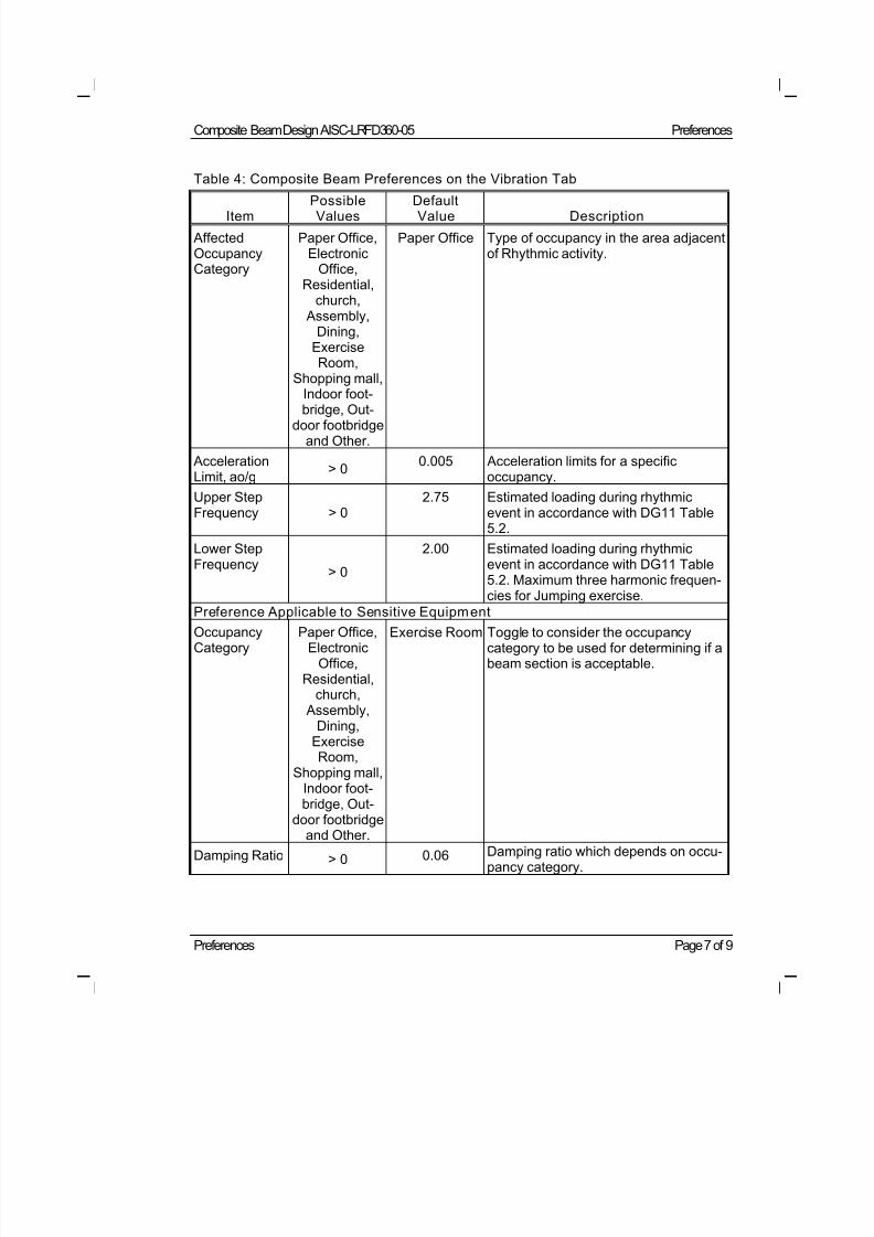
Paper Office Type of occupancy in the area adjacentof Rhythmic activity.
AccelerationLimit, ao/g
> 00.005 Acceleration limits for a specific
occupancy.
Upper StepFrequency > 0
2.75 Estimated loading during rhythmicevent in accordance with DG11 Table5.2.
Lower StepFrequency
> 0
2.00 Estimated loading during rhythmicevent in accordance with DG11 Table5.2. Maximum three harmonic frequen-cies for Jumping exercise.
Preference Applicable to Sensitive Equipment
OccupancyCategory
Paper Office,Electronic
Office,Residential,
church, Assembly,
Dining,ExerciseRoom,
Shopping mall,Indoor foot-bridge, Out-
door footbridgeand Other.
Exercise Room Toggle to consider the occupancycategory to be used for determining if abeam section is acceptable.
Damping Ratio > 0 0.06 Damping ratio which depends on occu-pancy category.
8/21/2019 Composit Beam
http://slidepdf.com/reader/full/composit-beam 31/161
Preferences Composite Beam Design AISC-LRFD360-05
Technical Note Page 8 of 9
Table 4: Composite Beam Preferences on the Vibration Tab
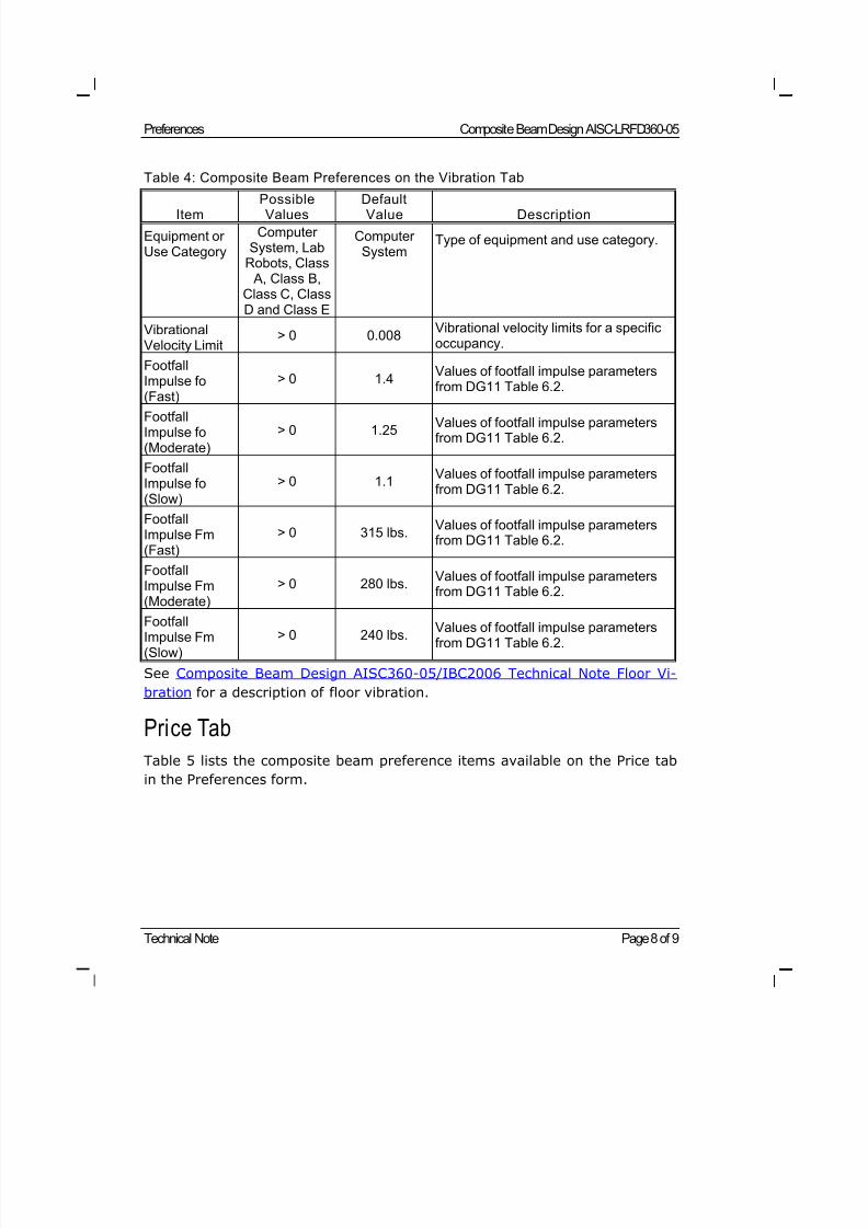
Item PossibleValues DefaultValue Description
Equipment orUse Category
ComputerSystem, Lab
Robots, Class A, Class B,
Class C, ClassD and Class E
ComputerSystem
Type of equipment and use category.
VibrationalVelocity Limit
> 0 0.008Vibrational velocity limits for a specificoccupancy.
FootfallImpulse fo(Fast)
> 0 1.4Values of footfall impulse parametersfrom DG11 Table 6.2.
FootfallImpulse fo(Moderate)
> 0 1.25Values of footfall impulse parametersfrom DG11 Table 6.2.
FootfallImpulse fo(Slow)
> 0 1.1Values of footfall impulse parametersfrom DG11 Table 6.2.
FootfallImpulse Fm(Fast)
> 0 315 lbs.Values of footfall impulse parametersfrom DG11 Table 6.2.
FootfallImpulse Fm(Moderate)
> 0 280 lbs.Values of footfall impulse parametersfrom DG11 Table 6.2.
FootfallImpulse Fm(Slow)
> 0 240 lbs.Values of footfall impulse parametersfrom DG11 Table 6.2.
See Composite Beam Design AISC360-05/IBC2006 Technical Note Floor Vi-
bration for a description of floor vibration.
Price Tab
Table 5 lists the composite beam preference items available on the Price tab
in the Preferences form.
8/21/2019 Composit Beam
http://slidepdf.com/reader/full/composit-beam 32/161
Composite Beam Design AISC-LRFD360-05 Preferences
Preferences Page 9 of 9
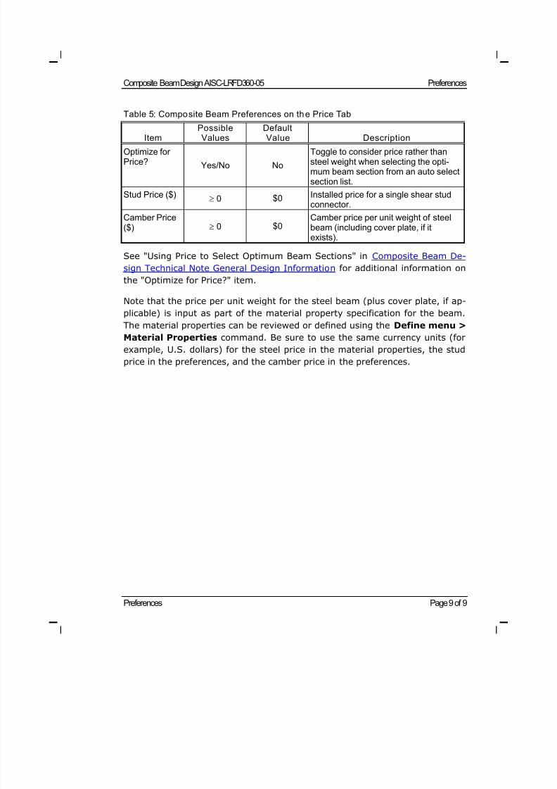
Table 5: Composite Beam Preferences on the Price Tab
Item PossibleValues DefaultValue Description
Optimize forPrice? Yes/No No
Toggle to consider price rather thansteel weight when selecting the opti-mum beam section from an auto selectsection list.
Stud Price ($) 0 $0 Installed price for a single shear stud
connector.
Camber Price($) 0 $0
Camber price per unit weight of steelbeam (including cover plate, if itexists).
See "Using Price to Select Optimum Beam Sections" in Composite Beam De-
sign Technical Note General Design Information for additional information on
the "Optimize for Price?" item.
Note that the price per unit weight for the steel beam (plus cover plate, if ap-
plicable) is input as part of the material property specification for the beam.
The material properties can be reviewed or defined using the Define menu >
Material Properties command. Be sure to use the same currency units (for
example, U.S. dollars) for the steel price in the material properties, the stud
price in the preferences, and the camber price in the preferences.
8/21/2019 Composit Beam
http://slidepdf.com/reader/full/composit-beam 33/161
Overwrites Page 1 of 17
©COMPUTERS AND STRUCTURES, INC., BERKELEY, C ALIFORNIA JUNE 2009
COMPOSITEBEAMDESIGN AISC-LRFD360-05
Technical Note
Overwrites
This Technical Note provides instructions on how to use the Composite Beam
Overwrites form and describes the items available on each of the tabs in the
form. One section is devoted to each of the tabs.
General
The composite beam design overwrites are basic assignments that apply onlyto those composite beams to which they are assigned. After selecting one or
more composite beams, use the Design menu > Composite Beam Design
> View\Revise Overwrites command to access the Composite Beam Over-
writes form; the form can be used to view and revise the composite beam de-
sign overwrites. Default values are provided for all composite beam overwrite
items. Thus, it is not necessary to specify or change any of the overwrites.
However, at least review the default values for the overwrite items to make
sure they are acceptable. When changes are made to overwrite items, the
program applies the changes only to the elements to which they are specifi-
cally assigned; that is, to the elements that are selected when the overwrites
are changed.
The Composite Beam Overwrites form has eight tabs. They are Beam, Bracing
(C), Bracing, Deck, Shear Studs, Deflection, Vibration and Miscellaneous. De-
scriptions of the various overwrite options available on each tab are provided
later in this Technical Note.
Using the Composite Beam Overwrites Form
After selecting one or more composite beams, use the Design menu >
Composite Beam Design > View\Revise Overwrites command to access
the Composite Beam Overwrites form. Click on the desired tab.
The Composite Beam Overwrites are displayed on each tab with a column of
check boxes and a two-column spreadsheet. The left column in the spread-
8/21/2019 Composit Beam
http://slidepdf.com/reader/full/composit-beam 34/161
Overwrites Composite Beam Design AISC-LRFD360-05
Page 2 of 17 Overwrites
sheet contains the name of the overwrite item. The right column in the
spreadsheet contains the overwrite value.
Initially, the check boxes are all unchecked and all of the cells in the spread-
sheet have a gray background to indicate they are inactive and that the items
in the cells currently cannot be changed. The names of the overwrite items in
the first column of the spreadsheet are visible. The values of the overwrite
items in the second column of the spreadsheet are visible only if one beam
was selected before the Composite Beam Overwrites form was accessed. If
multiple beams were selected, no values show for the overwrite items in the
second column of the spreadsheet.
After selecting one or multiple beams, check the box to the left of an over-
write item to change it. Then left click in either column of the spread sheet to
activate a drop-down box or to highlight the contents of the cell in the right
column of the spreadsheet. If the drop-down box appears, select a value from
the box. If the cell is highlighted, type in the desired value.
When a check box is checked or one of the columns in the spreadsheet is
clicked, a short description of the item in that row displays in the large text
box just below the list of items. This description explains the purpose of the
overwrite iteml.
When changes to the composite beam overwrites have been made, click the
OK button to close the form. The program then changes all of the overwriteitems whose associated check boxes are checked for the selected beam(s).
You must click the OK button for the changes to be accepted by the program.
If you click the Cancel button to exit the form, any changes made to the
overwrites will be ignored and the form will be closed.
Resetting Composite Beam Overwrites to Default Values
To set all of the composite beam overwrite items on a particular tab to their
default values, click on the tab and then click the Reset Tab button. This but-
ton resets the overwrite values on the tab currently selected.
To set all of the composite beam overwrite items on all tabs to their defaultvalues, click the Reset All button. This button immediately resets all of the
composite beam overwrite items. Alternatively, clicking the Design menu >
8/21/2019 Composit Beam
http://slidepdf.com/reader/full/composit-beam 35/161
Composite Beam Design AISC-LRFD360-05 Overwrites
Overwrites Page 3 of 17
Composite Beam Design > Reset All Composite Beam Overwrites
command will accomplish the same thing.
I m p o r t a n t n o t e a b o u t r es e t t in g o v e r w r i t e s: The defaults for the over-
write items are built into the program. The composite beam overwrite values
that were in a .edb file used to initialize a model may be different from the
built-in program default values. When the overwrites are reset, the program
resets the overwrite values to its built-in values, not to the values that were
in the .edb file used to initialize the model.
Overwrites
For purposes of explanation in this Technical Note, the overwrite items are
presented in tables. The column headings in these tables are described as fol-lows.
Item: The name of the overwrite item as it appears in the cells at the left
side of the Composite Beam Overwrites form.
Possible Values: The possible values for the associated overwrite item.
Default Value: The built-in default value that the program assumes for
the associated overwrite item.
Description: A description of the associated overwrite item.
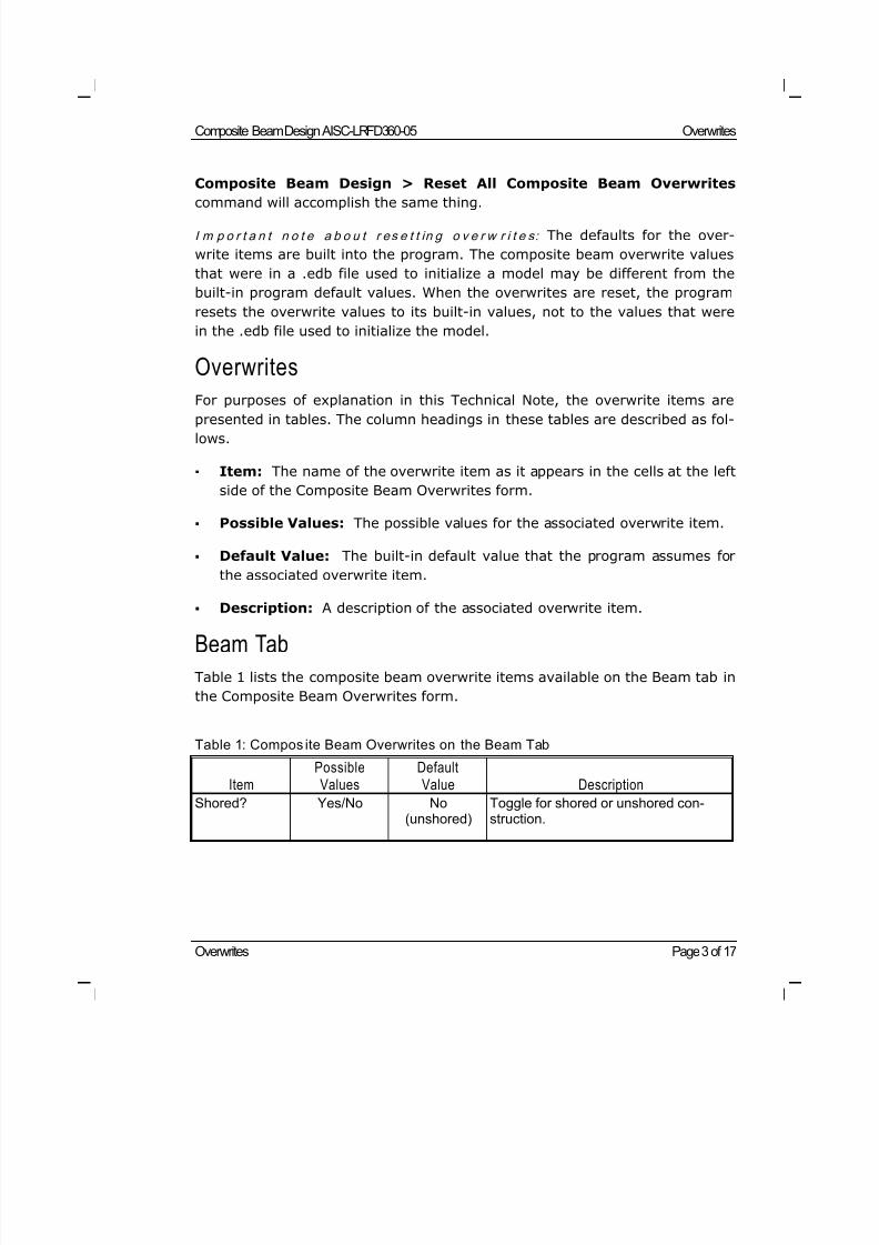
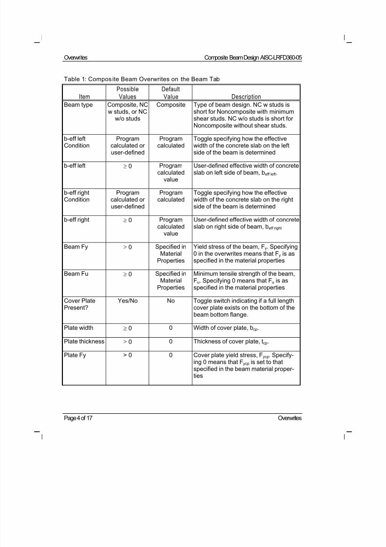
Beam Tab
Table 1 lists the composite beam overwrite items available on the Beam tab in
the Composite Beam Overwrites form.
Table 1: Compos ite Beam Overwrites on the Beam Tab
ItemPossibleValues
DefaultValue Description
Shored? Yes/No No(unshored)
Toggle for shored or unshored con-struction.
8/21/2019 Composit Beam
http://slidepdf.com/reader/full/composit-beam 36/161
Overwrites Composite Beam Design AISC-LRFD360-05
Page 4 of 17 Overwrites
Table 1: Compos ite Beam Overwrites on the Beam Tab
Item PossibleValues DefaultValue Description
Beam type Composite, NCw studs, or NC
w/o studs
Composite Type of beam design. NC w studs isshort for Noncomposite with minimumshear studs. NC w/o studs is short forNoncomposite without shear studs.
b-eff leftCondition
Programcalculated oruser-defined
Programcalculated
Toggle specifying how the effectivewidth of the concrete slab on the leftside of the beam is determined
b-eff left 0 Programcalculated
value
User-defined effective width of concreteslab on left side of beam, beff left.
b-eff rightCondition
Programcalculated oruser-defined
Programcalculated
Toggle specifying how the effectivewidth of the concrete slab on the rightside of the beam is determined
b-eff right 0 Programcalculated
value
User-defined effective width of concreteslab on right side of beam, beff right
Beam Fy 0 Specified inMaterial
Properties
Yield stress of the beam, Fy. Specifying0 in the overwrites means that Fy is asspecified in the material properties
Beam Fu 0 Specified inMaterial
Properties
Minimum tensile strength of the beam,Fu. Specifying 0 means that Fu is asspecified in the material properties
Cover PlatePresent?
Yes/No No Toggle switch indicating if a full lengthcover plate exists on the bottom of thebeam bottom flange.
Plate width 0 0 Width of cover plate, bcp.
Plate thickness 0 0 Thickness of cover plate, tcp.
Plate Fy > 0 0 Cover plate yield stress, Fycp. Specify-ing 0 means that Fycp is set to that
specified in the beam material proper-ties
8/21/2019 Composit Beam
http://slidepdf.com/reader/full/composit-beam 37/161
Composite Beam Design AISC-LRFD360-05 Overwrites
Overwrites Page 5 of 17
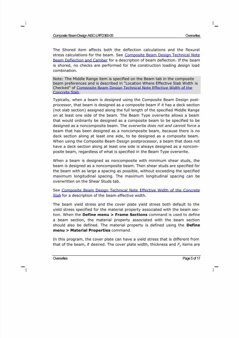
The Shored item affects both the deflection calculations and the flexural
stress calculations for the beam. See Composite Beam Design Technical NoteBeam Deflection and Camber for a description of beam deflection. If the beam
is shored, no checks are performed for the construction loading design load
combination.
Note: The Middle Range item is specified on the Beam tab in the composite
beam preferences and is described in "Location Where Effective Slab Width isChecked" of Composite Beam Design Technical Note Effective Width of the
Concrete Slab.
Typically, when a beam is designed using the Composite Beam Design post-
processor, that beam is designed as a composite beam if it has a deck section
(not slab section) assigned along the full length of the specified Middle Range
on at least one side of the beam. The Beam Type overwrite allows a beam
that would ordinarily be designed as a composite beam to be specified to be
designed as a noncomposite beam. The overwrite does not and cannot force a
beam that has been designed as a noncomposite beam, because there is no
deck section along at least one side, to be designed as a composite beam.
When using the Composite Beam Design postprocessor, a beam that does not
have a deck section along at least one side is always designed as a noncom-
posite beam, regardless of what is specified in the Beam Type overwrite.
When a beam is designed as noncomposite with minimum shear studs, the
beam is designed as a noncomposite beam. Then shear studs are specified for
the beam with as large a spacing as possible, without exceeding the specified
maximum longitudinal spacing. The maximum longitudinal spacing can be
overwritten on the Shear Studs tab.
See Composite Beam Design Technical Note Effective Width of the Concrete
Slab for a description of the beam effective width.
The beam yield stress and the cover plate yield stress both default to the
yield stress specified for the material property associated with the beam sec-
tion. When the Define menu > Frame Sections command is used to define
a beam section, the material property associated with the beam section
should also be defined. The material property is defined using the Definemenu > Material Properties command.
In this program, the cover plate can have a yield stress that is different from
that of the beam, if desired. The cover plate width, thickness and F y items are
8/21/2019 Composit Beam
http://slidepdf.com/reader/full/composit-beam 38/161
Overwrites Composite Beam Design AISC-LRFD360-05
Page 6 of 17 Overwrites
not active unless the "Cover Plate Present" item is set to Yes. See "Cover
Plates" in Composite Beam Design Technical Note Composite Beam Propertiesfor a description of cover plates.
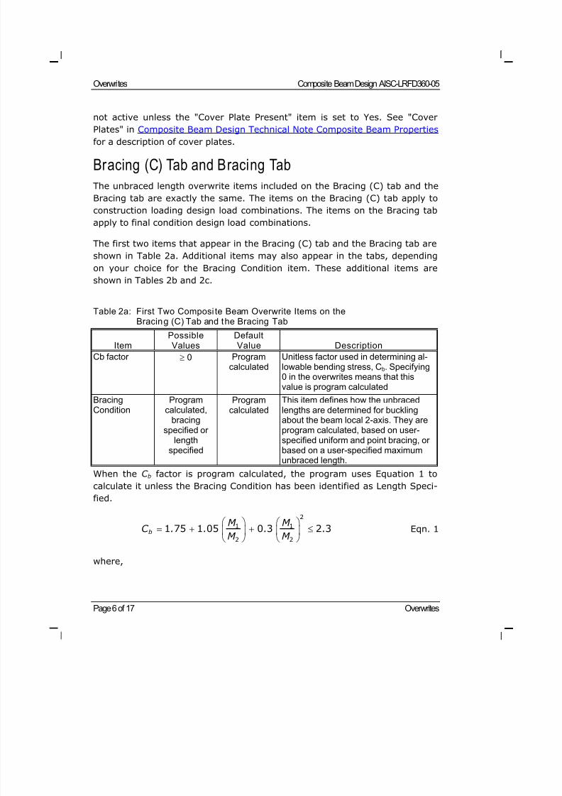
Bracing (C) Tab and Bracing Tab
The unbraced length overwrite items included on the Bracing (C) tab and the
Bracing tab are exactly the same. The items on the Bracing (C) tab apply to
construction loading design load combinations. The items on the Bracing tab
apply to final condition design load combinations.
The first two items that appear in the Bracing (C) tab and the Bracing tab are
shown in Table 2a. Additional items may also appear in the tabs, depending
on your choice for the Bracing Condition item. These additional items areshown in Tables 2b and 2c.
Table 2a: First Two Composi te Beam Overwrite Items on theBracing (C) Tab and the Bracing Tab
ItemPossibleValues
DefaultValue Description
Cb factor 0 Programcalculated
Unitless factor used in determining al-lowable bending stress, Cb. Specifying0 in the overwrites means that thisvalue is program calculated
BracingCondition
Programcalculated,
bracingspecified or
lengthspecified
Programcalculated
This item defines how the unbracedlengths are determined for bucklingabout the beam local 2-axis. They areprogram calculated, based on user-specified uniform and point bracing, orbased on a user-specified maximumunbraced length.
When the C b factor is program calculated, the program uses Equation 1 to
calculate it unless the Bracing Condition has been identified as Length Speci-
fied.
b
M M
C . . . .M M
2
1 1
2 21 75 1 05 0 3 2 3 Eqn. 1
where,
8/21/2019 Composit Beam
http://slidepdf.com/reader/full/composit-beam 39/161
Composite Beam Design AISC-LRFD360-05 Overwrites
Overwrites Page 7 of 17
M 1 and M 2 are the end moments of any unbraced span of the beam. M 1 is
numerically less than M 2.
The ratio M 1 /M 2 is positive for double curvature bending and negative for
single curvature bending within the unbraced beam span.
If any moment within the unbraced beam span is greater than M 2, the
numeric value of C b is 1.0.
The numeric value of C b is 1.0 for cantilever overhangs.
When the C b factor is program calculated and the Bracing Condition is set in
the overwrites to Length Specified, the program uses 1.0 for C b.
When the Bracing Condition is specified as Program Calculated, the program
assumes the beam is braced as described in "Determination of the Braced
Points of a Beam" in Composite Beam Design Technical Note Beam Unbraced
Length and Design Check Locations. Note that the program automatically con-
siders the bracing for construction loading and for the final condition sepa-
rately. For the construction loading condition, the program assumes that the
concrete fill does not assist in bracing the beam.
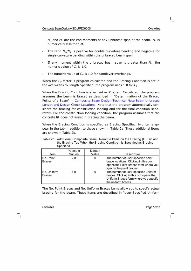
When the Bracing Condition is specified as Bracing Specified, two items ap-
pear in the tab in addition to those shown in Table 2a. Those additional items
are shown in Table 2b.
Table 2b: Additional Composi te Beam Overwri te Items on the Bracing (C) Tab andthe Bracing Tab When the Bracing Condition Is Specified as BracingSpecified
ItemPossibleValues
DefaultValue Description
No. PointBraces
0 0 The number of user-specified pointbrace locations. Clicking in this boxopens the Point Braces form where youspecify the point braces.
No. UniformBraces
0 0 The number of user-specified uniformbraces. Clicking in this box opens theUniform Braces form where you specify
the uniform braces.
The No. Point Braces and No. Uniform Braces items allow you to specify actual
bracing for the beam. These items are described in "User-Specified Uniform
8/21/2019 Composit Beam
http://slidepdf.com/reader/full/composit-beam 40/161
Overwrites Composite Beam Design AISC-LRFD360-05
Page 8 of 17 Overwrites
and Point Bracing" in Composite Beam Design Technical Note Beam Unbraced
Length and Design Check Locations.
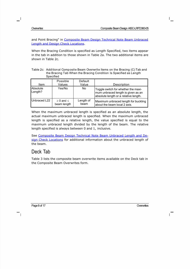
When the Bracing Condition is specified as Length Specified, two items appear
in the tab in addition to those shown in Table 2a. The two additional items are
shown in Table 2c.
Table 2c: Addi tional Composite Beam Overwrite Items on the Bracing (C) Tab andthe Bracing Tab When the Bracing Condition Is Specified as LengthSpecified
ItemPossibleValues
DefaultValue Description
AbsoluteLength?
Yes/No NoToggle switch for whether the maxi-mum unbraced length is given as anabsolute length or a relative length.
Unbraced L22 0 and beam length
Length ofbeam
Maximum unbraced length for bucklingabout the beam local 2 axis.
When the maximum unbraced length is specified as an absolute length, the
actual maximum unbraced length is specified. When the maximum unbraced
length is specified as a relative length, the value specified is equal to the
maximum unbraced length divided by the length of the beam. The relative
length specified is always between 0 and 1, inclusive.
See Composite Beam Design Technical Note Beam Unbraced Length and De-sign Check Locations for additional information about the unbraced length of
the beam.
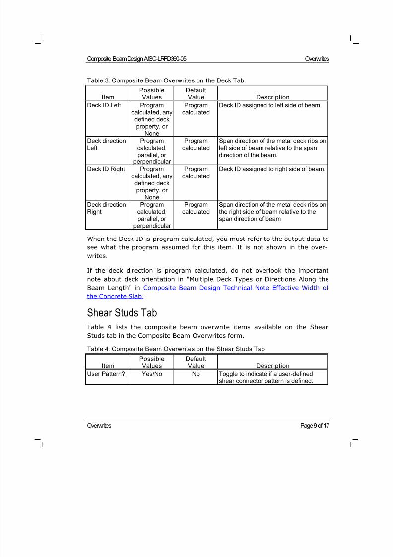
Deck Tab
Table 3 lists the composite beam overwrite items available on the Deck tab in
the Composite Beam Overwrites form.
8/21/2019 Composit Beam
http://slidepdf.com/reader/full/composit-beam 41/161
Composite Beam Design AISC-LRFD360-05 Overwrites
Overwrites Page 9 of 17
Table 3: Compos ite Beam Overwrites on the Deck Tab
Item PossibleValues DefaultValue Description
Deck ID Left Programcalculated, anydefined deckproperty, or
None
Programcalculated
Deck ID assigned to left side of beam.
Deck directionLeft
Programcalculated,parallel, or
perpendicular
Programcalculated
Span direction of the metal deck ribs onleft side of beam relative to the spandirection of the beam.
Deck ID Right Programcalculated, anydefined deckproperty, or
None
Programcalculated
Deck ID assigned to right side of beam.
Deck directionRight
Programcalculated,parallel, or
perpendicular
Programcalculated
Span direction of the metal deck ribs onthe right side of beam relative to thespan direction of beam
When the Deck ID is program calculated, you must refer to the output data to
see what the program assumed for this item. It is not shown in the over-
writes.
If the deck direction is program calculated, do not overlook the important
note about deck orientation in "Multiple Deck Types or Directions Along theBeam Length" in Composite Beam Design Technical Note Effective Width of
the Concrete Slab.
Shear Studs Tab
Table 4 lists the composite beam overwrite items available on the Shear
Studs tab in the Composite Beam Overwrites form.
Table 4: Compos ite Beam Overwrites on the Shear Studs Tab
ItemPossibleValues
DefaultValue Description
User Pattern? Yes/No No Toggle to indicate if a user-definedshear connector pattern is defined.
8/21/2019 Composit Beam
http://slidepdf.com/reader/full/composit-beam 42/161
Overwrites Composite Beam Design AISC-LRFD360-05
Page 10 of 17 Overwrites
Table 4: Compos ite Beam Overwrites on the Shear Studs Tab
Item PossibleValues DefaultValue Description
UniformSpacing
0 0, indicatingthere are no
uniformlyspaced
connectors
Uniform spacing of shear studs alongthe beam. There is one shear stud perrow along the beam.
No. AdditionalSections
0 0, indicatingthere are noadditional
connectorsspecified
Number of sections in which additionaluniformly spaced shear studs arespecified. Clicking in this box opens the
Additional Sections form where youspecify the section length and the num-ber of uniformly spaced connectors inthe section.
Min LongSpacing
> 0 6ds (i.e., six studdiameters)
Minimum longitudinal spacing of shearstuds along the length of the beam.
Max LongSpacing
> 0 36 inches Maximum longitudinal spacing of shearstuds along the length of the beam.
Min TranSpacing
> 0 4ds (i.e., four stud
diameters)
Minimum transverse spacing of shearstuds across the beam flange.
Max Studsper Row
> 0 3 Maximum number of shear studs in asingle row across the beam flange.
Qn Programcalculated or
> 0
Programcalculated
Capacity of a single shear stud. Speci-fying 0 in the overwrites means that thisvalue is program calculated.
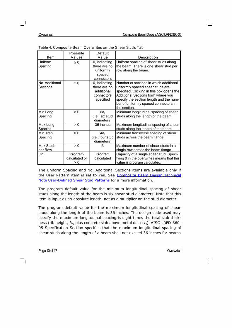
The Uniform Spacing and No. Additional Sections items are available only if
the User Pattern item is set to Yes. See Composite Beam Design Technical
Note User-Defined Shear Stud Patterns for a more information.
The program default value for the minimum longitudinal spacing of shear
studs along the length of the beam is six shear stud diameters. Note that this
item is input as an absolute length, not as a multiplier on the stud diameter.
The program default value for the maximum longitudinal spacing of shear
studs along the length of the beam is 36 inches. The design code used may
specify the maximum longitudinal spacing is eight times the total slab thick-
ness (rib height, hr , plus concrete slab above metal deck, t c ). AISC-LRFD-360-
05 Specification Section specifies that the maximum longitudinal spacing of
shear studs along the length of a beam shall not exceed 36 inches for beams
8/21/2019 Composit Beam
http://slidepdf.com/reader/full/composit-beam 43/161
Composite Beam Design AISC-LRFD360-05 Overwrites
Overwrites Page 11 of 17
when the span of the metal deck is perpendicular to the span of the beam. If
your total slab thickness is less than 36"/8 = 4.5", the program default valuemay be unconservative and should be revised.
The program default value for the minimum transverse spacing of shear studs
across the beam flange is four shear stud diameters. This is consistent with
the last paragraph of AISC-LRFD-360-05 Specification Section I5. Note that
this item is input as an absolute length, not as a multiplier on the stud diame-
ter. See Composite Beam Design Technical Note Distribution of Shear Studs
on a Composite Beam for an additional description of how shear studs are dis-
tributed on composite beams.
The "Max Studs per Row" item indicates the maximum number of shear studs
that is allowed in a row across the beam flange. For wider beams, the Min
Tran Spacing item might indicate that more studs could be accommodated
across the beam flange but the Max Studs per Row item will limit the number
of studs in any row. See Composite Beam Design Technical Note Distribution
of Shear Studs on a Composite Beam for an additional description of how
shear studs are distributed on beams.
See "Shear Stud Connector" in Composite Beam Design AISC-ASD89 Techni-
cal Note Shear Studs for a description of how the program calculates the al-
lowable shear load for a single shear stud. Note that when a q value is speci-
fied in the overwrites, the program assumes that the specified value of q has
already been modified by any applicable reduction factors for the metal deck.Finally, note that specifying 0 (zero) in the overwrites for this item means
that the allowable shear stud load is calculated by the program, not that it is
zero.
Shear studs are described in more detail in Composite Beam Design Technical
Note Distribution of Shear Studs on a Composite Beam, Technical Note The
Number of Shear Studs that Fit in a Composite Beam Segment, and Technical
Note User-Defined Shear Stud Patterns.
Deflection Tab
Table 5 lists the composite beam overwrite items available on the Deflection
tab in the Composite Beam Overwrites form.
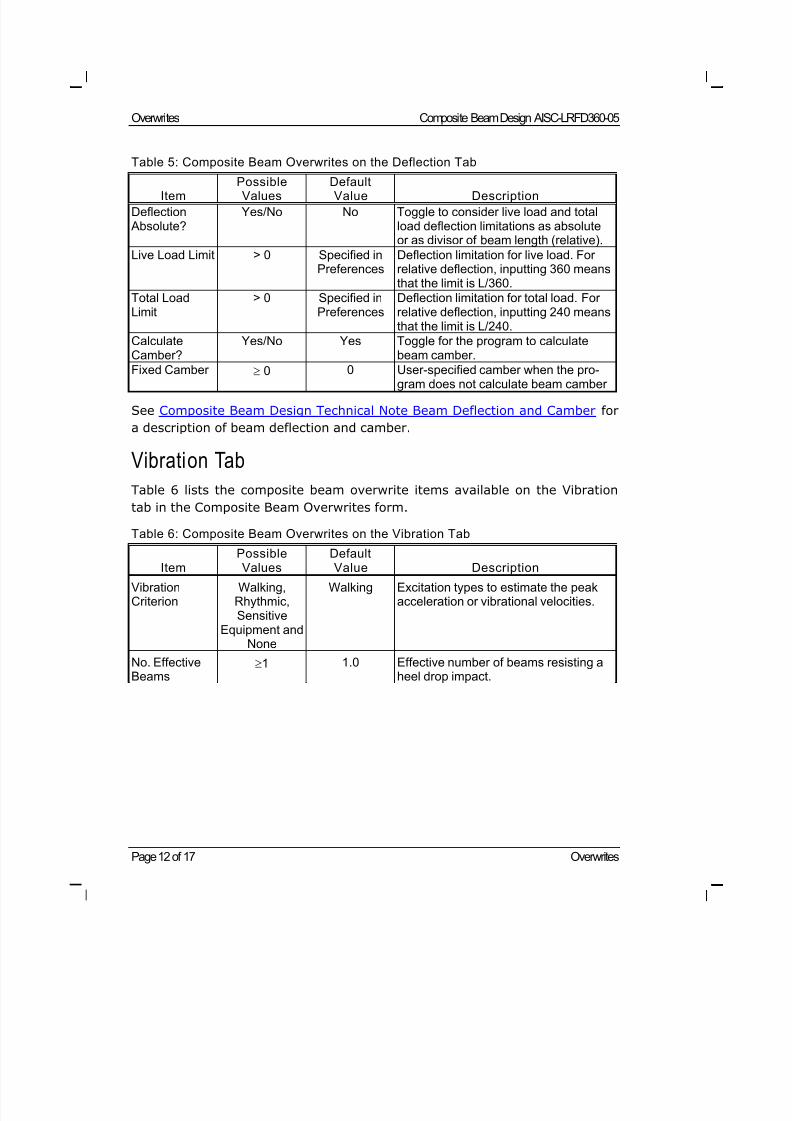
8/21/2019 Composit Beam
http://slidepdf.com/reader/full/composit-beam 44/161
Overwrites Composite Beam Design AISC-LRFD360-05
Page 12 of 17 Overwrites
Table 5: Composite Beam Overwrites on the Deflection Tab
Item PossibleValues DefaultValue Description
Deflection Absolute?
Yes/No No Toggle to consider live load and totalload deflection limitations as absoluteor as divisor of beam length (relative).
Live Load Limit > 0 Specified inPreferences
Deflection limitation for live load. Forrelative deflection, inputting 360 meansthat the limit is L/360.
Total LoadLimit
> 0 Specified inPreferences
Deflection limitation for total load. Forrelative deflection, inputting 240 meansthat the limit is L/240.
CalculateCamber?
Yes/No Yes Toggle for the program to calculatebeam camber.
Fixed Camber 0 0 User-specified camber when the pro-gram does not calculate beam camber
See Composite Beam Design Technical Note Beam Deflection and Camber for
a description of beam deflection and camber.
Vibration Tab
Table 6 lists the composite beam overwrite items available on the Vibration
tab in the Composite Beam Overwrites form.
Table 6: Composite Beam Overwrites on the Vibration Tab
Item
Possible
Values
Default
Value Description
VibrationCriterion
Walking,Rhythmic,Sensitive
Equipment andNone
Walking Excitation types to estimate the peakacceleration or vibrational velocities.
No. EffectiveBeams
1 1.0 Effective number of beams resisting aheel drop impact.
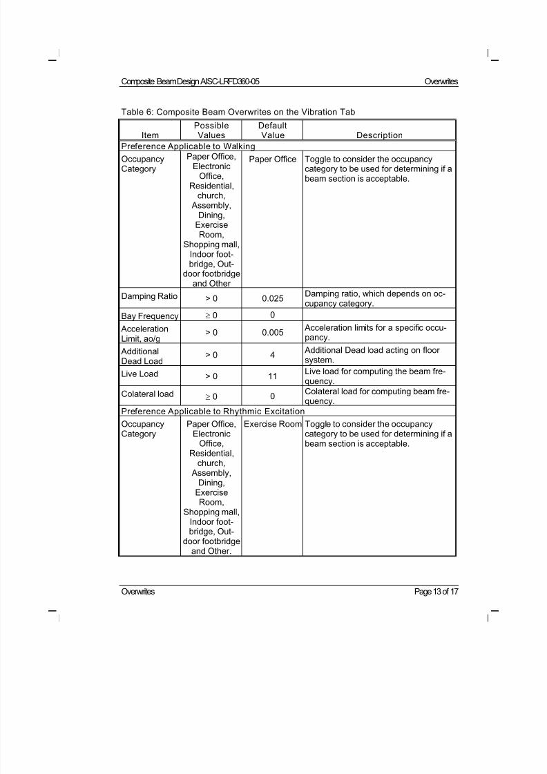
8/21/2019 Composit Beam
http://slidepdf.com/reader/full/composit-beam 45/161
Composite Beam Design AISC-LRFD360-05 Overwrites
Overwrites Page 13 of 17
Table 6: Composite Beam Overwrites on the Vibration Tab
Item PossibleValues DefaultValue Description
Preference Applicable to Walking
OccupancyCategory
Paper Office,Electronic
Office,Residential,
church, Assembly,
Dining,ExerciseRoom,
Shopping mall,Indoor foot-bridge, Out-
door footbridgeand Other
Paper Office Toggle to consider the occupancycategory to be used for determining if abeam section is acceptable.
Damping Ratio > 0 0.025Damping ratio, which depends on oc-cupancy category.
Bay Frequency 0 0
AccelerationLimit, ao/g
> 0 0.005 Acceleration limits for a specific occu-pancy.
AdditionalDead Load
> 0 4 Additional Dead load acting on floorsystem.
Live Load > 0 11Live load for computing the beam fre-quency.
Colateral load 0 0 Colateral load for computing beam fre-quency.
Preference Applicable to Rhythmic Excitation
OccupancyCategory
Paper Office,Electronic
Office,Residential,
church, Assembly,
Dining,ExerciseRoom,
Shopping mall,
Indoor foot-bridge, Out-
door footbridgeand Other.
Exercise Room Toggle to consider the occupancycategory to be used for determining if abeam section is acceptable.
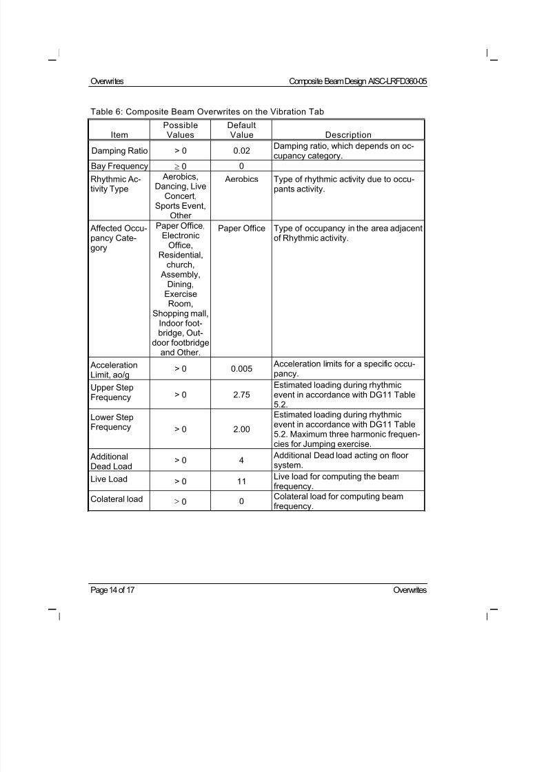
8/21/2019 Composit Beam
http://slidepdf.com/reader/full/composit-beam 46/161
Overwrites Composite Beam Design AISC-LRFD360-05
Page 14 of 17 Overwrites
Table 6: Composite Beam Overwrites on the Vibration Tab
Item PossibleValues DefaultValue Description
Damping Ratio > 0 0.02Damping ratio, which depends on oc-cupancy category.
Bay Frequency 0 0
Rhythmic Ac-tivity Type
Aerobics,Dancing, Live
Concert,Sports Event,
Other
Aerobics Type of rhythmic activity due to occu-pants activity.
Affected Occu-pancy Cate-gory
Paper Office,Electronic
Office,
Residential,church, Assembly,
Dining,ExerciseRoom,
Shopping mall,Indoor foot-bridge, Out-
door footbridgeand Other.
Paper Office Type of occupancy in the area adjacentof Rhythmic activity.
AccelerationLimit, ao/g
> 0 0.005 Acceleration limits for a specific occu-pancy.
Upper StepFrequency > 0 2.75 Estimated loading during rhythmicevent in accordance with DG11 Table
5.2.
Lower StepFrequency > 0 2.00
Estimated loading during rhythmicevent in accordance with DG11 Table5.2. Maximum three harmonic frequen-cies for Jumping exercise.
AdditionalDead Load
> 0 4 Additional Dead load acting on floorsystem.
Live Load > 0 11Live load for computing the beamfrequency.
Colateral load 0 0Colateral load for computing beamfrequency.
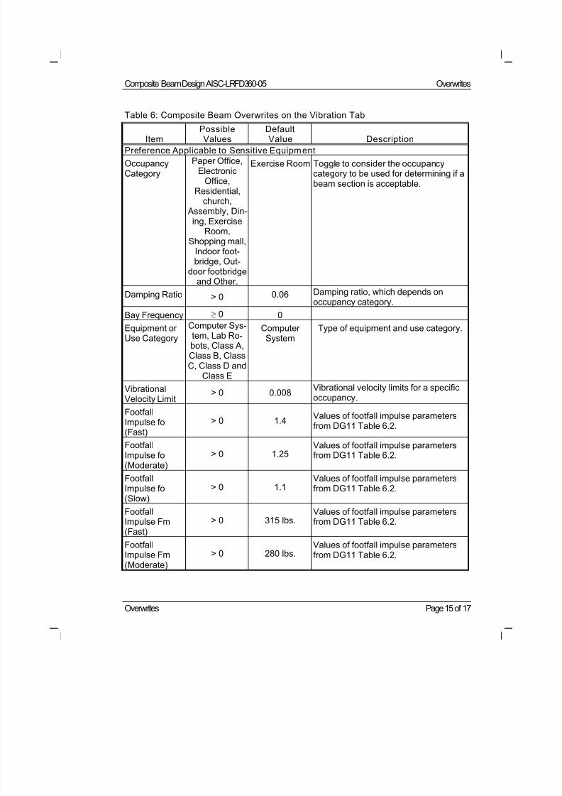
8/21/2019 Composit Beam
http://slidepdf.com/reader/full/composit-beam 47/161
Composite Beam Design AISC-LRFD360-05 Overwrites
Overwrites Page 15 of 17
Table 6: Composite Beam Overwrites on the Vibration Tab
Item PossibleValues DefaultValue Description
Preference Applicable to Sensitive Equipment
OccupancyCategory
Paper Office,Electronic
Office,Residential,
church, Assembly, Din-
ing, ExerciseRoom,
Shopping mall,Indoor foot-bridge, Out-
door footbridgeand Other.
Exercise Room Toggle to consider the occupancycategory to be used for determining if abeam section is acceptable.
Damping Ratio > 0 0.06 Damping ratio, which depends onoccupancy category.
Bay Frequency 0 0
Equipment orUse Category
Computer Sys-tem, Lab Ro-bots, Class A,Class B, ClassC, Class D and
Class E
ComputerSystem
Type of equipment and use category.
Vibrational
Velocity Limit
> 0 0.008Vibrational velocity limits for a specific
occupancy.FootfallImpulse fo(Fast)
> 0 1.4Values of footfall impulse parametersfrom DG11 Table 6.2.
FootfallImpulse fo(Moderate)
> 0 1.25Values of footfall impulse parametersfrom DG11 Table 6.2.
FootfallImpulse fo(Slow)
> 0 1.1Values of footfall impulse parametersfrom DG11 Table 6.2.
FootfallImpulse Fm
(Fast)
> 0 315 lbs.Values of footfall impulse parametersfrom DG11 Table 6.2.
FootfallImpulse Fm(Moderate)
> 0 280 lbs.Values of footfall impulse parametersfrom DG11 Table 6.2.
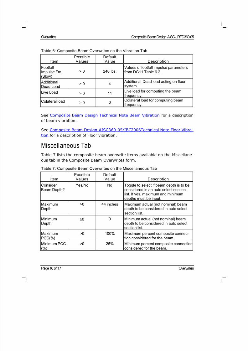
8/21/2019 Composit Beam
http://slidepdf.com/reader/full/composit-beam 48/161
Overwrites Composite Beam Design AISC-LRFD360-05
Page 16 of 17 Overwrites
Table 6: Composite Beam Overwrites on the Vibration Tab
Item PossibleValues DefaultValue Description
FootfallImpulse Fm(Slow)
> 0 240 lbs.Values of footfall impulse parametersfrom DG11 Table 6.2.
AdditionalDead Load
> 0 4 Additional Dead load acting on floorsystem.
Live Load > 0 11Live load for computing the beamfrequency.
Colateral load 0 0Colateral load for computing beamfrequency.
See Composite Beam Design Technical Note Beam Vibration for a description
of beam vibration.
See Composite Beam Design AISC360-05/IBC2006Technical Note Floor Vibra-
tion for a description of Floor vibration.
Miscellaneous Tab
Table 7 lists the composite beam overwrite items available on the Miscellane-
ous tab in the Composite Beam Overwrites form.
Table 7: Composite Beam Overwrites on the Miscellaneous Tab
Item PossibleValues DefaultValue Description
ConsiderBeam Depth?
Yes/No No Toggle to select if beam depth is to beconsidered in an auto select sectionlist. If yes, maximum and minimumdepths must be input.
MaximumDepth
>0 44 inches Maximum actual (not nominal) beamdepth to be considered in auto selectsection list.
MinimumDepth
0 0 Minimum actual (not nominal) beamdepth to be considered in auto selectsection list.
MaximumPCC(%) >0 100% Maximum percent composite connec-tion considered for the beam.
Minimum PCC(%)
>0 25% Minimum percent composite connectionconsidered for the beam.
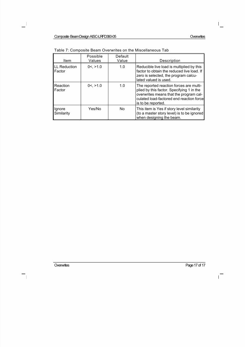
8/21/2019 Composit Beam
http://slidepdf.com/reader/full/composit-beam 49/161
Composite Beam Design AISC-LRFD360-05 Overwrites
Overwrites Page 17 of 17
Table 7: Composite Beam Overwrites on the Miscellaneous Tab
Item PossibleValues DefaultValue Description
LL ReductionFactor
0<, >1.0 1.0 Reducible live load is multiplied by thisfactor to obtain the reduced live load. Ifzero is selected, the program calcu-lated valued is used.
ReactionFactor
0<, >1.0 1.0 The reported reaction forces are multi-plied by this factor. Specifying 1 in theoverwrites means that the program cal-culated load-factored end reaction forceis to be reported.
IgnoreSimilarity
Yes/No No This item is Yes if story level similarity(to a master story level) is to be ignored
when designing the beam.
8/21/2019 Composit Beam
http://slidepdf.com/reader/full/composit-beam 50/161
Design Load Combinations Page 1 of 4
©COMPUTERS AND STRUCTURES, INC., BERKELEY, C ALIFORNIA JUNE 2009
COMPOSITEBEAMDESIGN AISC-LRFD 360-05
Technical Note
Design Load Combinations
This Technical Note defines the default AISC-LRFD 360-05 composite beam
design load combinations. General information about composite beam design
load combinations is provided by Composite Beam Design Technical Note De-
sign Load Combinations.
Default composite beam design load combinations can be used for design, or
the user may define design load combinations, or both default and user-defined combinations can be used for design. The default design load combi-
nations can be modified and deleted as necessary. Use the Design Menu >
Composite Beam Design > Select Design Combo command to access the
design load combinations selection form.
Strength Check for Construction Loads
The program performs only the check using the construction load design load
combination if the beam is unshored. If the beam is shored, the check for
construction loads is not performed and any specified design load combina-
tions for construction loads are not relevant.
The automatically created design load combination, using the AISC-LRFD 360-
05 specification, for checking the strength of an unshored beam subjected to
construction loads is given by Equation 1.
1.6 (WDL) + 1.6 [0.2 (LL + RLL)] Eqn. 1
where,
WDL = The sum of all wet dead load (WDL) load cases defined for
the model. Note that if a load case is simply defined as dead
load, it is assumed to be a WDL load case.
LL = The sum of all live load (LL) load cases defined for the
model.
8/21/2019 Composit Beam
http://slidepdf.com/reader/full/composit-beam 51/161
Design Load Combinations Composite Beam Design AISC-LRFD 360-05
Page 2 of 4 Design Load Combinations
RLL = The sum of all reducible live load (RLL) load cases defined
for the model.
In Equation 1 the term 0.2 (LL + RLL) is an assumed construction live load.
Note that the load factor for dead loads is assumed the same as that for live
load when considering construction loads (e.g., placing of concrete, and the
like). See R. Vogel (1991).
Strength Check for Final Loads
The automatically created design load combinations for checking the strength
of a composite beam under final loads are given by Equations 2 and 3.
1.4 (WDL + SDL) Eqn. 2
1.2 (WDL + SDL) + 1.6 (LL + RLL) Eqn. 3
where,
SDL = The sum of all superimposed dead load (SDL) load cases
defined for the model.
and the remainder of the terms are as defined for Equation 1.
Deflection Check for Final Loads
The automatically created design load combination for checking the deflection
of a composite beam under final loads is given by Equation 4.
WDL + SDL + LL + RLL Eqn. 4
where all of the terms are as described for Equations 1 through 3. Note that
all of the load factors for this serviceability check are 1.0.
If the beam is unshored, the WDL portion of the deflection is based on the
moment of inertia of the steel beam alone and the remainder of the deflection
is based on the effective moment of inertia of the composite section. If the
beam is shored, the entire deflection is based on the effective moment of in-
ertia of the composite section.
8/21/2019 Composit Beam
http://slidepdf.com/reader/full/composit-beam 52/161
Composite Beam Design AISC-LRFD 360-05 Design Load Combinations
Design Load Combinations Page 3 of 4
Reference
Vogel, R. 1991. “LRFD-Composite Beam Design with Metal Deck,” Steel Tips,
Technical Information & Product Service, Steel Committee of Califor-
nia, March

8/21/2019 Composit Beam
http://slidepdf.com/reader/full/composit-beam 53/161
8/21/2019 Composit Beam
http://slidepdf.com/reader/full/composit-beam 54/161
Compact and Noncompact Requirements Page 1 of 7
©COMPUTERS AND STRUCTURES, INC., BERKELEY, C ALIFORNIA JUNE 2009
COMPOSITEBEAMDESIGN AISC-LRFD 360-05
Technical Note
Compact and Noncompact Requirements
This Technical Note describes how the program checks the AISC-LRFD 360-05
specification requirements for compact and noncompact beams. The basic
compact and noncompact requirements checked are in AISC-LRFD 360-05
Chapter B, Table 4.1. The program checks the width-to-thickness ratios of the
beam compression flange, beam web, and, if it exists and is in compression,
the cover plate. When a singly symmetric beam is designed for noncomposite
behavior, it is also checked for lateral torsional buckling requirements.
Overview
The program classifies beam sections as either plastic, compact, noncompact
or slender. It checks the plastic, compact and noncompact section require-
ments at each design location along the beam for each design load combina-
tion separately. A beam section may be classified differently for different de-
sign load combinations. For example, a beam may be classified as compact
for design load combination A and as noncompact for design load combination
B. Two reasons that a beam may be classified differently for different design
load cases are as follows:
The compact section requirements for beam webs depend on the axial
load in the beam. Different design load combinations may produce differ-
ent axial loads in the beam. This is only an issue when beam axial loads
are specified to be considered in the composite beam analysis and design.
The compression flange may be different for different design load combi-
nations. If the sizes of the top and bottom flanges are not the same, clas-
sification of the section may depend on which flange is determined to be
the compression flange.
At each design location, for each design load combination, the program first
checks a beam section for the compact section requirements for the compres-
sion flange, web, cover plate (if applicable) and lateral torsional buckling (if
applicable) described herein. If the beam section meets all of those require-
ments, it is classified as compact for that design load combination. If the
8/21/2019 Composit Beam
http://slidepdf.com/reader/full/composit-beam 55/161
Compact and Noncompact Requirements Composite Beam Design AISC-LRFD 360-05
Compact and Noncompact Requirements Page 2 of 7
beam section does not meet all of the compact section requirements, it is
checked for the noncompact requirements for the flanges, web, cover plate (ifapplicable) and lateral torsional buckling (if applicable) described herein. If
the beam section meets all of those requirements, it is classified as noncom-
pact for that design load combination. If the beam section does not meet all
of the noncompact section requirements, it is classified as slender for that de-
sign load combination, and the program does not consider it for composite
beam design.
Limiting Width-to-Thickness Ratios for Flanges
This section describes the limiting width-to-thickness ratios considered by the
program for beam compression flanges. The width-to-thickness ratio for
flanges is denoted b /t , and is equal to bf /2t f for I-shaped sections and bf /t f for
channel sections.
Compact Section Limits for Flanges
For compact sections, the width-to-thickness ratio for the compression flange
is limited to that indicated by Equation 1.
0.38 ,yf
b E
t F for compact sections Eqn. 1
where F yf is the specified yield stress of the flange considered. Equation 1 ap-
plies to both rolled sections selected from the program's database and touser-defined sections.
Noncompact Section Limits for Flanges
I - S h a p e d R o l l e d B e am s a n d Ch a n n e l s
For noncompact I-shaped rolled beams and channels, the width-to-thickness
ratio for the compression flange is limited to that indicated by Equation 2.
y
b E
t F 1.0 , for noncompact sections Eqn. 2
where F y is the specified yield stress of the beam or channel.
8/21/2019 Composit Beam
http://slidepdf.com/reader/full/composit-beam 56/161
Composite Beam Design AISC-LRFD 360-05 Compact and Noncompact Requirements
Compact and Noncompact Requirements Page 3 of 7
User-Defined and Hybrid Beams
For noncompact user-defined and hybrid beams, the width-to-thickness ratiofor the compression flange is limited to that indicated by Equation 3.
c
L
K E b
t F 0.95 , for noncompact sections Eqn. 3
where F yf is the yield stress of the compression flange and,
c c
w
k k h
t
4
but not less than 0.35 0.76 Eqn. 4
F L=0.7F y for minor-axis bending, major axis bending of slender-web built-up
I-shaped members with S xt /S xc ≥ 0.7; F L = F y S xt /S xc ≥ 0.5F y for major axis
bending of compact and noncompact web built-up I-shaped members with
S xt /S xc < 0.7.
Limi ting Width-to-Thickness Ratios for Webs
This section describes the limiting width-to-thickness ratios considered by the
program for beam webs.
Compact Section Limits for Webs
When checking a beam web for compact section requirements, the width-to-thickness ratio used is h /t w . The equation used for checking the compact sec-
tion limits in the web depends on the ratio of the elastic neutral axis to theplastic neutral axis and the ratio of
p y M /M :
The program uses b = 0.9 for both elastic and plastic stress distribution
resulting from flexure.
Equation 5 defines the compact section limit for webs. For flexure in webs
of doubly symmetric I-shaped sections and channels:
3.76w y
h E
t F Eqn. 5a
For flexure in webs of singly-symmetric I-shaped sections:
8/21/2019 Composit Beam
http://slidepdf.com/reader/full/composit-beam 57/161
Compact and Noncompact Requirements Composite Beam Design AISC-LRFD 360-05
Compact and Noncompact Requirements Page 4 of 7
2 5.70
0.54 0.09
c y
py
w p y
hE F
hh E F t M M
Eqn. 5b
In Equations 5a and 5b, the value of F y used is the largest of the F y values for
the beam flanges and the web.
Noncompact Section Limit s for Webs
When checking a beam web for noncompact section requirements, the width-
to-thickness ratio used is h /t w . The noncompact section limits depend on
whether the flanges of the beam are of equal or unequal size.
Equation 6 defines the noncompact section limit for webs:
w y
h E
t F5.70 Eqn. 6
Limi ting Width-to-Thickness Ratios for Cover Plates
The width-to-thickness checks made for the cover plate depend on the width
of the cover plate compared to the width of the beam bottom flange. Figure 1
illustrates the conditions considered.
In Case A of the figure, the width of the cover plate is less than or equal to
the width of the beam bottom flange. In that case, the width-to-thickness ra-
tio is taken as b1 /t cp, and it is checked as a flange cover plate.
In Case B of Figure 1, the width of the cover plate is greater than the width of
the beam bottom flange. Two conditions are checked in that case. The first
condition is the same as that shown in Case A, where the width-to-thickness
ratio is taken as b1 /t cp and is checked as a flange cover plate. The second
condition checked in Case B takes b2 /t cp as the width-to-thickness ratio and
checks it as a plate projecting from a beam. This second condition is only
checked for the noncompact requirements; it is not checked for compact re-quirements.
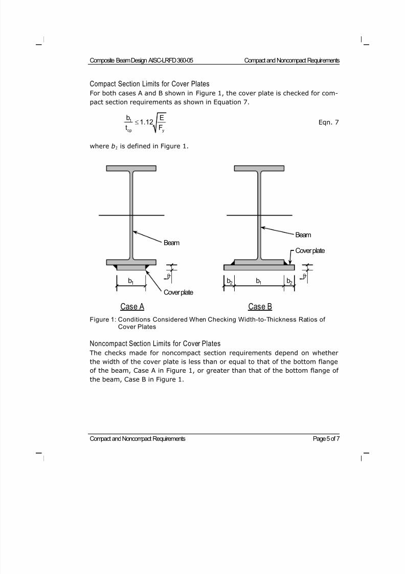
8/21/2019 Composit Beam
http://slidepdf.com/reader/full/composit-beam 58/161
Composite Beam Design AISC-LRFD 360-05 Compact and Noncompact Requirements
Compact and Noncompact Requirements Page 5 of 7
Compact Section Limits for Cover Plates
For both cases A and B shown in Figure 1, the cover plate is checked for com-pact section requirements as shown in Equation 7.
cp y
b E
t F1 1.12 Eqn. 7
where b1 is defined in Figure 1.
Figure 1: Conditions Considered When Checking Width-to-Thickness Ratios ofCover Plates
Noncompact Section Limits for Cover Plates
The checks made for noncompact section requirements depend on whether
the width of the cover plate is less than or equal to that of the bottom flange
of the beam, Case A in Figure 1, or greater than that of the bottom flange of
the beam, Case B in Figure 1.
b1 t c
p
b1 t c
p
b2b2
Case A Case B
Beam
Cover plate
Beam
Cover plate
8/21/2019 Composit Beam
http://slidepdf.com/reader/full/composit-beam 59/161
Compact and Noncompact Requirements Composite Beam Design AISC-LRFD 360-05
Compact and Noncompact Requirements Page 6 of 7
Cover Plate Width Beam Bottom Flange Width
When the cover plate width is less than or equal to the width of the beambottom flange, Equation 8 applies for the noncompact check for the cover
plate.
1 1.40
cp y
b E
t F Eqn. 8
The term b1 in Equation 8 is defined in Figure 1.
Cover Plate Width > Beam Bottom Flange Width
When the cover plate width exceeds the width of the beam bottom flange,
both Equations 8 and 9 apply for the noncompact check for the cover plate.
2 1.12
cp y
b E
t F Eqn. 9
The term b2 in Equation 9 is defined in Figure 1.
Lateral Torsional Buckl ing
When a singly symmetric beam is designed for noncomposite behavior, it is
checked for lateral torsional buckling requirements. If the singly symmetric
beam is unshored, this check occurs for any construction design load case. It
also occurs for beams that have negative bending that are not specified toconsider the composite action provided by the slab rebar. Finally, the check
occurs for any singly symmetric beam specified to be noncomposite.
When reviewing for lateral torsional buckling requirements, the value of Lb /r yc
is checked. Lb is the laterally unbraced length of beam; that is, the length be-
tween points that are braced against lateral displacement of the compression
flange. The term r yc is radius of gyration of the compression flange about the
y-axis.
Compact Limi ts for Lateral Torsional Buckling
The compact section limit for lateral torsional buckling is given in Equations
10, 11, and 12.
For double-symmetric compact I-shaped members and channels bent
about their major axis:
8/21/2019 Composit Beam
http://slidepdf.com/reader/full/composit-beam 60/161
Composite Beam Design AISC-LRFD 360-05 Compact and Noncompact Requirements
Compact and Noncompact Requirements Page 7 of 7
1.76b
yc y
L E
r F
Eqn. 10
For double-symmetric I-shaped members with compact webs and non-
compact or slender flanges bent about their major axis:
1.76b
yc y
L E
r F Eqn. 11
For double-symmetric compact I-shaped members and channels bent
about their major axis:
1.1b t
yc y
L E
r F Eqn. 12
In Equation 10, 11, and 12, the term F yf is the yield stress of the compression
flange.
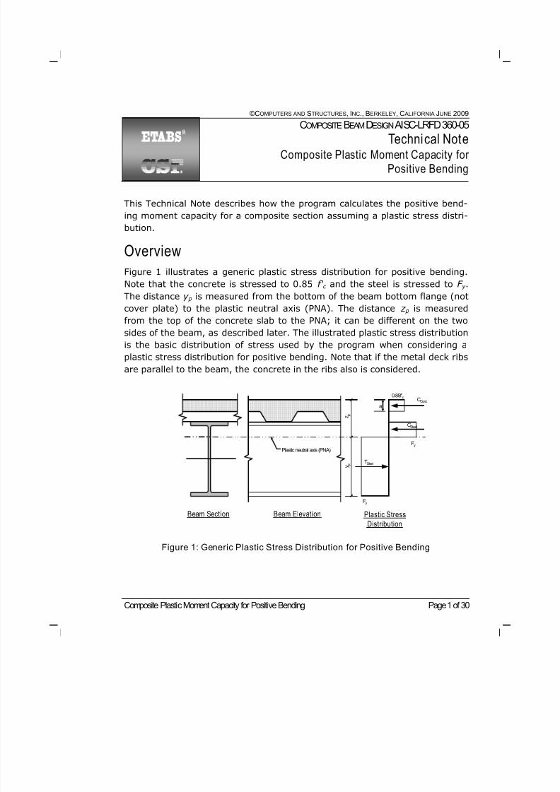
8/21/2019 Composit Beam
http://slidepdf.com/reader/full/composit-beam 61/161
Composite Plastic Moment Capacity for Positive Bending Page 1 of 30
©COMPUTERS AND STRUCTURES, INC., BERKELEY, C ALIFORNIA JUNE 2009
COMPOSITEBEAMDESIGN AISC-LRFD 360-05
Technical NoteComposite Plastic Moment Capacity for
Positive Bending
This Technical Note describes how the program calculates the positive bend-
ing moment capacity for a composite section assuming a plastic stress distri-
bution.
Overview
Figure 1 illustrates a generic plastic stress distribution for positive bending.
Note that the concrete is stressed to 0.85 f' c and the steel is stressed to F y .
The distance y p is measured from the bottom of the beam bottom flange (not
cover plate) to the plastic neutral axis (PNA). The distance z p is measured
from the top of the concrete slab to the PNA; it can be different on the two
sides of the beam, as described later. The illustrated plastic stress distribution
is the basic distribution of stress used by the program when considering a
plastic stress distribution for positive bending. Note that if the metal deck ribs
are parallel to the beam, the concrete in the ribs also is considered.
Figure 1: Generic Plastic Stress Distribution for Positive Bending
Beam Section Beam Elevation Plastic Stress
Distribution
CConc
CSteel
TSteel
0.85f’c
Fy
Fy
a
Plastic neutral axis (PNA)
y p
z p
8/21/2019 Composit Beam
http://slidepdf.com/reader/full/composit-beam 62/161
Composite Beam Design AISC-LRFD 360-05 Composite Plastic Moment Capacity for Positive Bending
Composite Plastic Moment Capacity for Positive Bending Page 2 of 30
Figure 2 illustrates how the program idealizes a steel beam for calculating the
plastic stress distribution. Two different cases are shown, one for a rolled sec-tion and the other for a user-defined section. The idealization for the rolled
section considers the fillets, whereas the idealization for the user-defined sec-
tion assumes there are no fillets because none are specified in the section
definition. Although not shown in those figures, the deck type and orientation
may be different on the left and right sides of the beam, as shown in Figure 2
of Composite Beam Design Technical Note Effective Width of the Concrete
Slab.
For a rolled steel section, the fillets are idealized as a rectangular block of
steel. The depth of this rectangular block, k depth, is:
k depth = k – t f Eqn. 1
The width of this rectangular block, k width, is:
k width = ( As – 2bf t f – (d – 2k )t w ) / 2k depth Eqn. 2
The basic steps in computing the positive plastic moment capacity are:
Determine the location of the PNA using Equations 3a through 10.
Calculate the plastic moment capacity of the composite section using Equa-
tion 11 together with the appropriate table chosen from Tables 2 through
11 depending on the location of the PNA. Note that for user-defined sec-tions, the terms related to the top and bottom fillets are ignored.
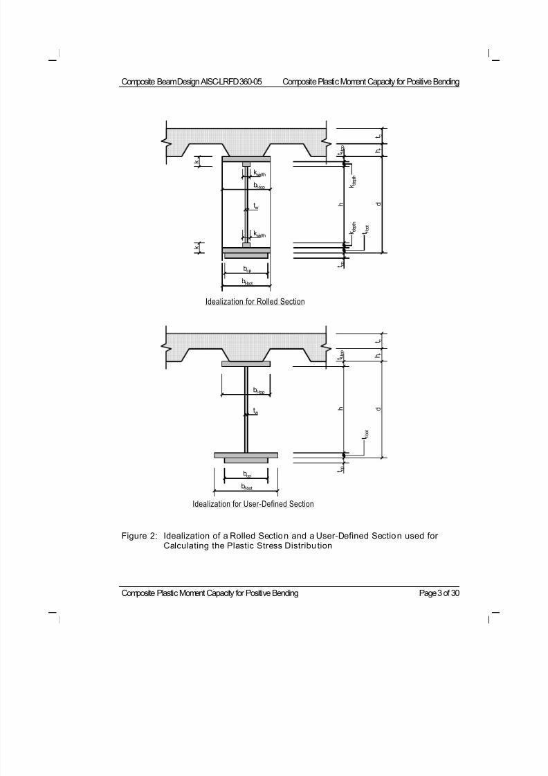
8/21/2019 Composit Beam
http://slidepdf.com/reader/full/composit-beam 63/161
Composite Beam Design AISC-LRFD 360-05 Composite Plastic Moment Capacity for Positive Bending
Composite Plastic Moment Capacity for Positive Bending Page 3 of 30
Figure 2: Idealization of a Rolled Section and a User-Defined Section used forCalculating the Plastic Stress Distribu tion
bcp
bf-bot
kwidth
kwidth
tw
bf-top
h r
t c
t f - t o p
k
k
d h
k d e p t h
k d e p t h
t c p
t f -
b o t
Idealization for Rolled Section
bcp
bf-bot
tw
bf-top
h r
t c
t f - t o p
d h
t c p
t f -
b o t
Idealization for User-Defined Section
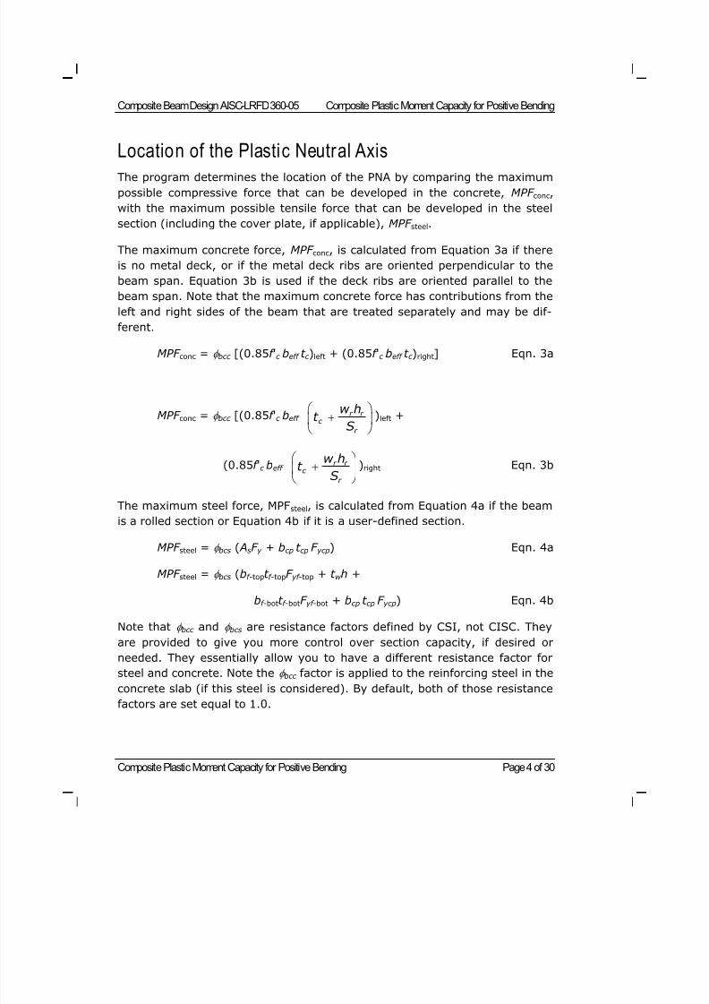
8/21/2019 Composit Beam
http://slidepdf.com/reader/full/composit-beam 64/161
Composite Beam Design AISC-LRFD 360-05 Composite Plastic Moment Capacity for Positive Bending
Composite Plastic Moment Capacity for Positive Bending Page 4 of 30
Location of the Plastic Neutral Axis
The program determines the location of the PNA by comparing the maximum
possible compressive force that can be developed in the concrete, MPF conc,
with the maximum possible tensile force that can be developed in the steel
section (including the cover plate, if applicable), MPF steel.
The maximum concrete force, MPF conc, is calculated from Equation 3a if there
is no metal deck, or if the metal deck ribs are oriented perpendicular to the
beam span. Equation 3b is used if the deck ribs are oriented parallel to the
beam span. Note that the maximum concrete force has contributions from the
left and right sides of the beam that are treated separately and may be dif-
ferent.
MPF conc = bcc [(0.85f 'c beff t c )left + (0.85f 'c beff t c )right] Eqn. 3a
MPF conc = bcc [(0.85f 'c beff r r
c
r
w ht
S
)left +
(0.85f 'c beff r r
c
r
w ht
S
)right Eqn. 3b
The maximum steel force, MPFsteel, is calculated from Equation 4a if the beamis a rolled section or Equation 4b if it is a user-defined section.
MPF steel = bcs ( AsF y + bcp t cp F ycp) Eqn. 4a
MPF steel = bcs (bf -topt f -topF yf -top + t w h +
bf -bott f -botF yf -bot + bcp t cp F ycp) Eqn. 4b
Note that bcc and bcs are resistance factors defined by CSI, not CISC. They
are provided to give you more control over section capacity, if desired or
needed. They essentially allow you to have a different resistance factor for
steel and concrete. Note the bcc factor is applied to the reinforcing steel in theconcrete slab (if this steel is considered). By default, both of those resistance
factors are set equal to 1.0.
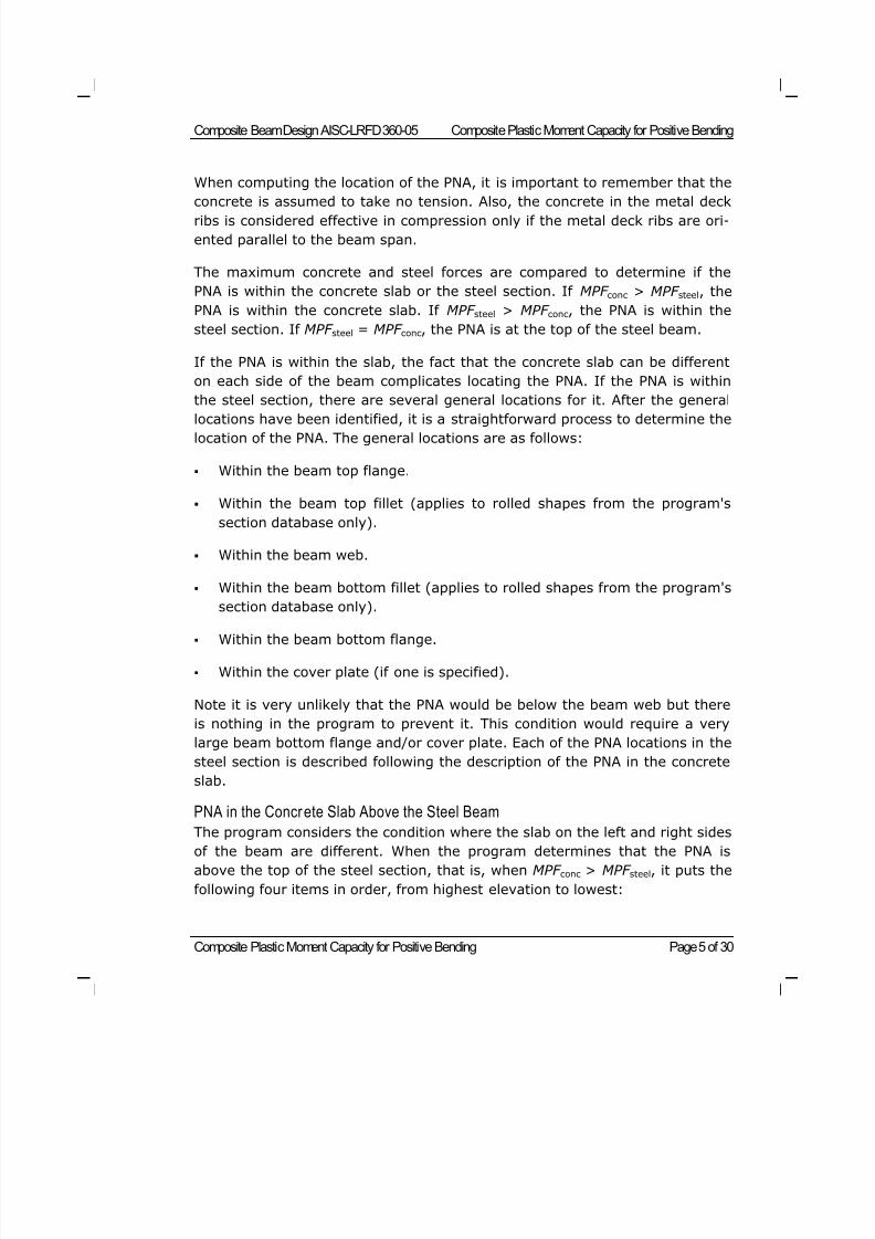
8/21/2019 Composit Beam
http://slidepdf.com/reader/full/composit-beam 65/161
Composite Beam Design AISC-LRFD 360-05 Composite Plastic Moment Capacity for Positive Bending
Composite Plastic Moment Capacity for Positive Bending Page 5 of 30
When computing the location of the PNA, it is important to remember that the
concrete is assumed to take no tension. Also, the concrete in the metal deckribs is considered effective in compression only if the metal deck ribs are ori-
ented parallel to the beam span.
The maximum concrete and steel forces are compared to determine if the
PNA is within the concrete slab or the steel section. If MPF conc > MPF steel, the
PNA is within the concrete slab. If MPF steel > MPF conc, the PNA is within the
steel section. If MPF steel = MPF conc, the PNA is at the top of the steel beam.
If the PNA is within the slab, the fact that the concrete slab can be different
on each side of the beam complicates locating the PNA. If the PNA is within
the steel section, there are several general locations for it. After the general
locations have been identified, it is a straightforward process to determine the
location of the PNA. The general locations are as follows:
Within the beam top flange.
Within the beam top fillet (applies to rolled shapes from the program's
section database only).
Within the beam web.
Within the beam bottom fillet (applies to rolled shapes from the program's
section database only).
Within the beam bottom flange.
Within the cover plate (if one is specified).
Note it is very unlikely that the PNA would be below the beam web but there
is nothing in the program to prevent it. This condition would require a very
large beam bottom flange and/or cover plate. Each of the PNA locations in the
steel section is described following the description of the PNA in the concrete
slab.
PNA in the Concrete Slab Above the Steel Beam
The program considers the condition where the slab on the left and right sidesof the beam are different. When the program determines that the PNA is
above the top of the steel section, that is, when MPF conc > MPF steel, it puts the
following four items in order, from highest elevation to lowest:
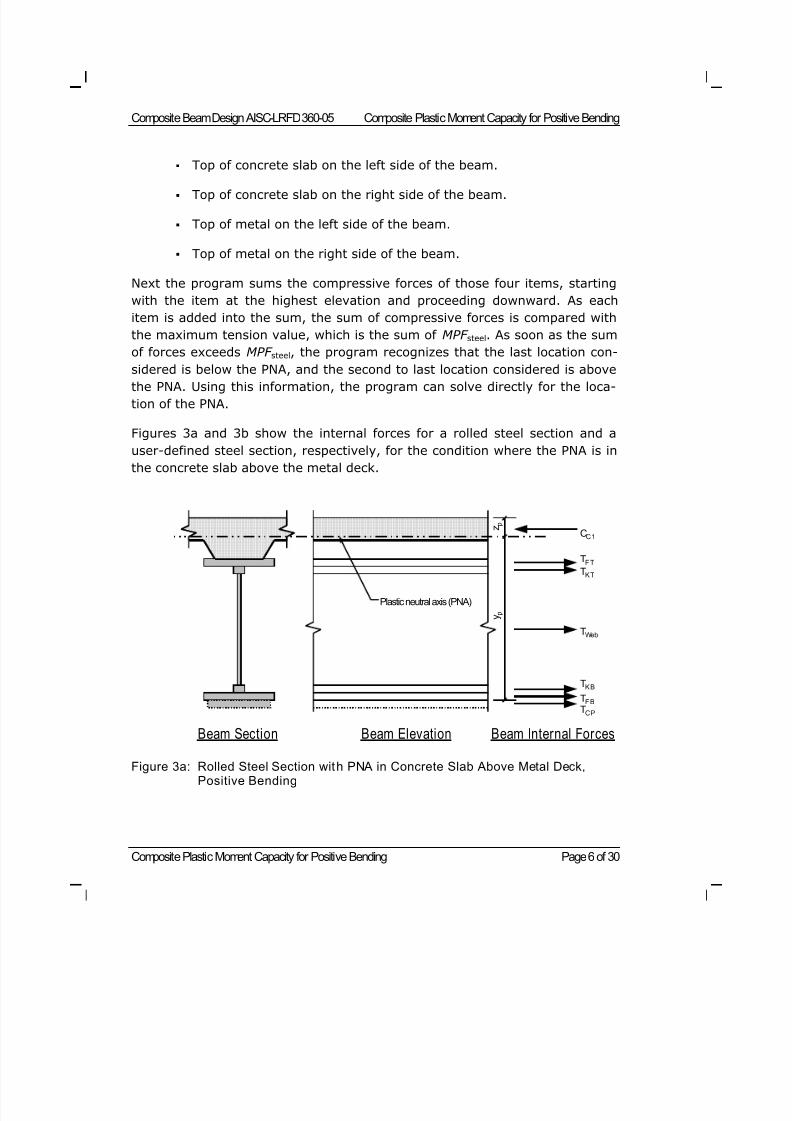
8/21/2019 Composit Beam
http://slidepdf.com/reader/full/composit-beam 66/161
Composite Beam Design AISC-LRFD 360-05 Composite Plastic Moment Capacity for Positive Bending
Composite Plastic Moment Capacity for Positive Bending Page 6 of 30
Top of concrete slab on the left side of the beam.
Top of concrete slab on the right side of the beam.
Top of metal on the left side of the beam.
Top of metal on the right side of the beam.
Next the program sums the compressive forces of those four items, starting
with the item at the highest elevation and proceeding downward. As each
item is added into the sum, the sum of compressive forces is compared with
the maximum tension value, which is the sum of MPF steel. As soon as the sum
of forces exceeds MPF steel, the program recognizes that the last location con-
sidered is below the PNA, and the second to last location considered is abovethe PNA. Using this information, the program can solve directly for the loca-
tion of the PNA.
Figures 3a and 3b show the internal forces for a rolled steel section and a
user-defined steel section, respectively, for the condition where the PNA is in
the concrete slab above the metal deck.
Figure 3a: Rolled Steel Section with PNA in Concrete Slab Above Metal Deck,Positive Bending
CC 1
Beam Section Beam Elevation Beam Internal Forces
TC P
Plastic neutral axis (PNA)
TF B
TK B
TWeb
TK TTF T
y p
z p
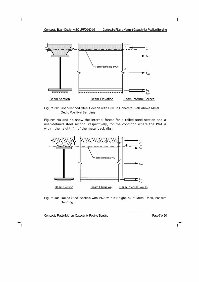
8/21/2019 Composit Beam
http://slidepdf.com/reader/full/composit-beam 67/161
Composite Beam Design AISC-LRFD 360-05 Composite Plastic Moment Capacity for Positive Bending
Composite Plastic Moment Capacity for Positive Bending Page 7 of 30
Figure 3b: User-Defined Steel Section with PNA in Concrete Slab Above Metal
Deck, Positive Bending
Figures 4a and 4b show the internal forces for a rolled steel section and a
user-defined steel section, respectively, for the condition where the PNA is
within the height, hr , of the metal deck ribs.
Figure 4a: Rolled Steel Section with PNA within Height, hr , of Metal Deck, Positive
Bending
C C 1
Beam Section Beam Elevat ion Beam In ternal Forces
C C 2 T F T
T F B T Web T C P
Plastic neutral axis (PNA)p
zp
CC 1
Beam Section Beam Elevation Beam Internal Forces
TF T
TF B
TWeb
TC P
Plastic neutral axis (PNA) y p
z
p
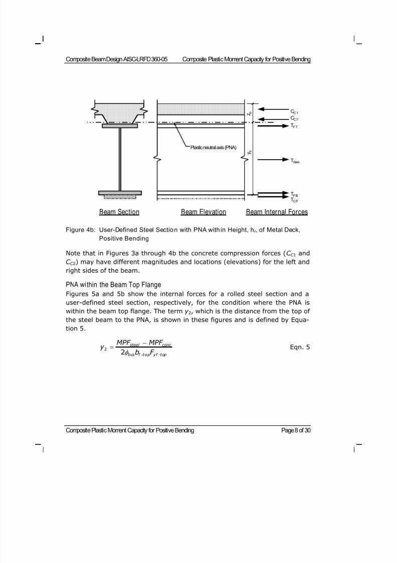
8/21/2019 Composit Beam
http://slidepdf.com/reader/full/composit-beam 68/161
Composite Beam Design AISC-LRFD 360-05 Composite Plastic Moment Capacity for Positive Bending
Composite Plastic Moment Capacity for Positive Bending Page 8 of 30
Figure 4b: User-Defined Steel Section with PNA with in Height, hr , of Metal Deck,
Positive Bending
Note that in Figures 3a through 4b the concrete compression forces (C C 1 and
C C 2) may have different magnitudes and locations (elevations) for the left and
right sides of the beam.
PNA wi thin the Beam Top FlangeFigures 5a and 5b show the internal forces for a rolled steel section and a
user-defined steel section, respectively, for the condition where the PNA is
within the beam top flange. The term y 2, which is the distance from the top of
the steel beam to the PNA, is shown in these figures and is defined by Equa-
tion 5.
steel conc
bcs f top yf top
MPF MPF y
b F
2
2 Eqn. 5
CC 1
Beam Section Beam Elevation Beam Internal Forces
CC 2
TF T
TF B
TWeb
TC P
Plastic neutral axis (PNA) y p
z p
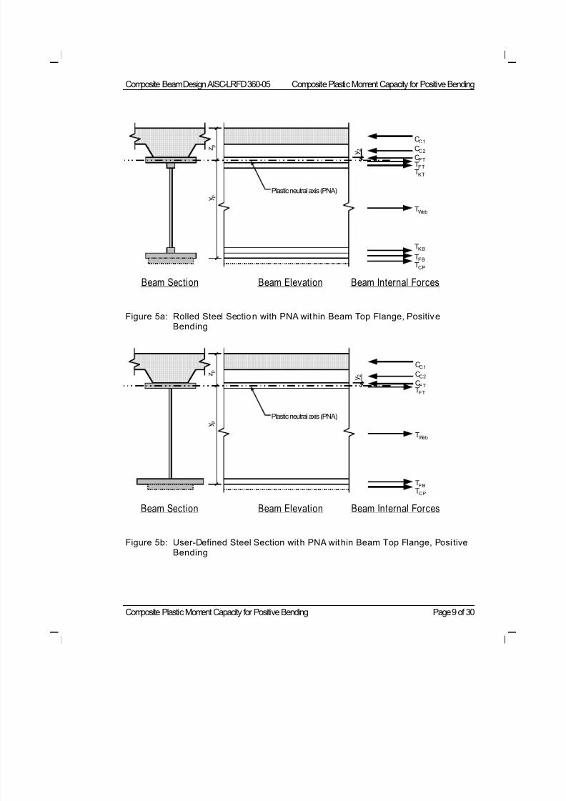
8/21/2019 Composit Beam
http://slidepdf.com/reader/full/composit-beam 69/161
Composite Beam Design AISC-LRFD 360-05 Composite Plastic Moment Capacity for Positive Bending
Composite Plastic Moment Capacity for Positive Bending Page 9 of 30
Figure 5a: Rolled Steel Section with PNA within Beam Top Flange, PositiveBending
Figure 5b: User-Defined Steel Section with PNA within Beam Top Flange, Posi tiveBending
CC 1
Beam Section Beam Elevation Beam Internal Forces
CC 2
TF TTK T
TF B
TK B
TWeb
TC P
Plastic neutral axis (PNA)
CF T
y 2
y p
z p
CC 1
Beam Section Beam Elevation Beam Internal Forces
CC 2
TF T
TF B
TWeb
TC P
Plastic neutral axis (PNA)
CF T
y 2
y p
z p
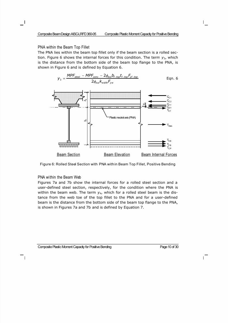
8/21/2019 Composit Beam
http://slidepdf.com/reader/full/composit-beam 70/161
Composite Beam Design AISC-LRFD 360-05 Composite Plastic Moment Capacity for Positive Bending
Composite Plastic Moment Capacity for Positive Bending Page 10 of 30
PNA within the Beam Top Fillet
The PNA lies within the beam top fillet only if the beam section is a rolled sec-tion. Figure 6 shows the internal forces for this condition. The term y 3, which
is the distance from the bottom side of the beam top flange to the PNA, is
shown in Figure 6 and is defined by Equation 6.
steel conc bcs f top f top yf top
bcs width yw
MPF MPF b t F y
k F
3
2
2 Eqn. 6
Figure 6: Rolled Steel Section with PNA with in Beam Top Fillet, Positive Bending
PNA wi thin the Beam Web
Figures 7a and 7b show the internal forces for a rolled steel section and a
user-defined steel section, respectively, for the condition where the PNA is
within the beam web. The term y 4, which for a rolled steel beam is the dis-
tance from the web toe of the top fillet to the PNA and for a user-defined
beam is the distance from the bottom side of the beam top flange to the PNA,
is shown in Figures 7a and 7b and is defined by Equation 7.
CC 1
Beam Section Beam Elevation Beam Internal Forces
CC 2
CK TTK T
TF B
TK B
TWeb
TC P
Plastic neutral axis (PNA)
CF T y 3
y p
z p
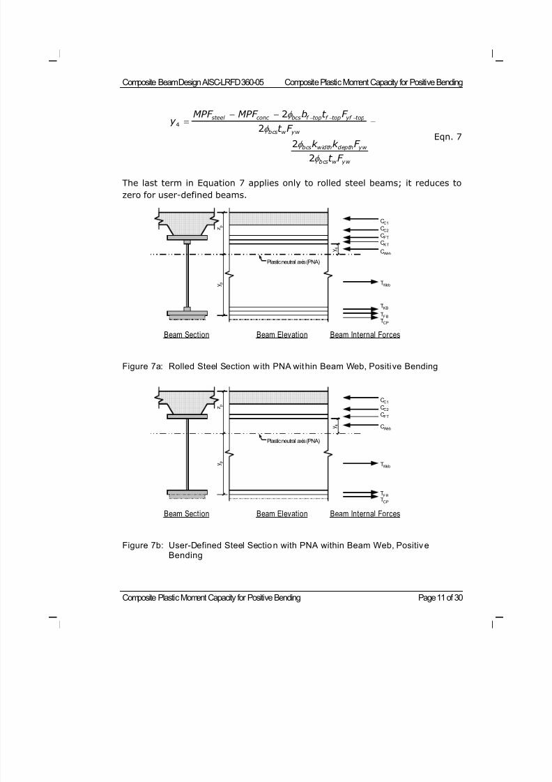
8/21/2019 Composit Beam
http://slidepdf.com/reader/full/composit-beam 71/161
Composite Beam Design AISC-LRFD 360-05 Composite Plastic Moment Capacity for Positive Bending
Composite Plastic Moment Capacity for Positive Bending Page 11 of 30
steel conc bcs f top f top yf top
bcs w yw
bcs width depth yw
bcs w yw
MPF MPF b t F y
t F k k F
t F
4
2
22
2
Eqn. 7
The last term in Equation 7 applies only to rolled steel beams; it reduces to
zero for user-defined beams.
Figure 7a: Rolled Steel Section with PNA within Beam Web, Positive Bending
Figure 7b: User-Defined Steel Section with PNA within Beam Web, PositiveBending
CC1
Beam Section Beam Elevation Beam Internal Forces
CC2
CWeb
TF B
TWeb
TCP
Plastic neutral axis (PNA)
CF T
y 4
y p
z p
CC1
Beam Section Beam Elevation Beam Internal Forces
CC2
CK T
CWeb
TF B
TKB
TWeb
TCP
Plastic neutral axis (PNA)
CF T
y 4
y p
z p
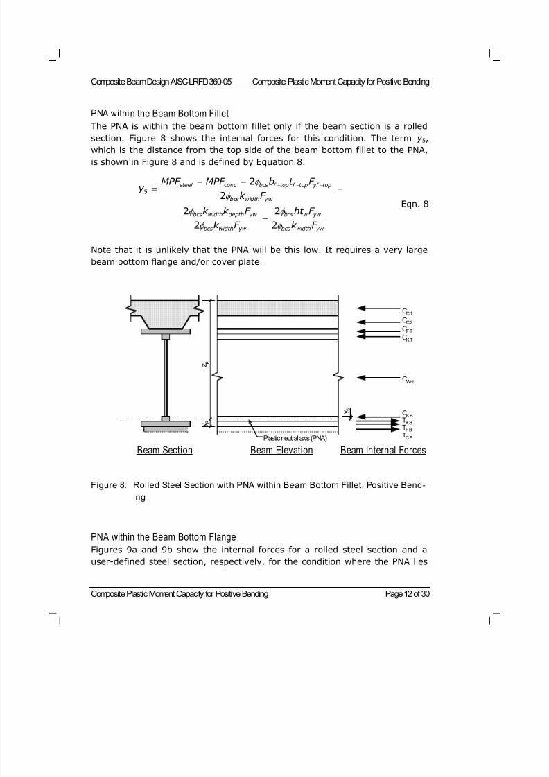
8/21/2019 Composit Beam
http://slidepdf.com/reader/full/composit-beam 72/161
Composite Beam Design AISC-LRFD 360-05 Composite Plastic Moment Capacity for Positive Bending
Composite Plastic Moment Capacity for Positive Bending Page 12 of 30
PNA within the Beam Bottom Fillet
The PNA is within the beam bottom fillet only if the beam section is a rolledsection. Figure 8 shows the internal forces for this condition. The term y 5,
which is the distance from the top side of the beam bottom fillet to the PNA,
is shown in Figure 8 and is defined by Equation 8.
steel conc bcs f top f top yf top
bcs width yw
bcs width depth yw bcs w yw
bcs width yw bcs width yw
MPF MPF b t F y
k F
k k F ht F
k F k F
5
2
2
2 2
2 2
Eqn. 8
Note that it is unlikely that the PNA will be this low. It requires a very large
beam bottom flange and/or cover plate.
Figure 8: Rolled Steel Section with PNA within Beam Bottom Fillet, Positive Bend-
ing
PNA within the Beam Bottom Flange
Figures 9a and 9b show the internal forces for a rolled steel section and a
user-defined steel section, respectively, for the condition where the PNA lies
CC 1
Beam Section Beam Elevation Beam Internal Forces
CC 2
CK T
CK B
TF B
TK B
CWeb
TC P
CF T
y 5
Plastic neutral axis (PNA)
y p
z p
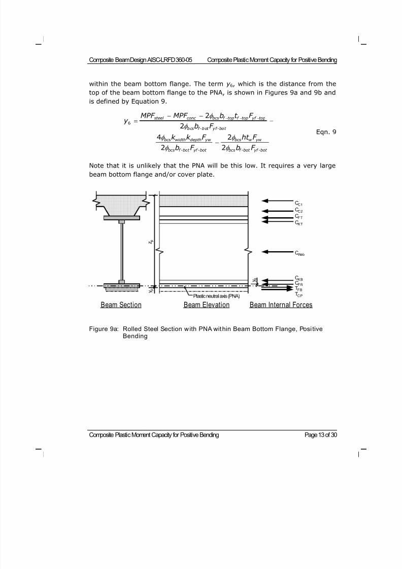
8/21/2019 Composit Beam
http://slidepdf.com/reader/full/composit-beam 73/161
Composite Beam Design AISC-LRFD 360-05 Composite Plastic Moment Capacity for Positive Bending
Composite Plastic Moment Capacity for Positive Bending Page 13 of 30
within the beam bottom flange. The term y 6, which is the distance from the
top of the beam bottom flange to the PNA, is shown in Figures 9a and 9b andis defined by Equation 9.
steel conc bcs f top f top yf top
bcs f-bot yf-bot
bcs width depth yw bcs w yw
bcs f -bot yf -bot bcs f -bot yf -bot
MPF MPF b t F y
b F
k k F ht F
b F b F
6
2
2
4 2
2 2
Eqn. 9
Note that it is unlikely that the PNA will be this low. It requires a very large
beam bottom flange and/or cover plate.
Figure 9a: Rolled Steel Section with PNA within Beam Bottom Flange, Posi tiveBending
CC 1
Beam Section Beam Elevation Beam Internal Forces
CC 2
CK T
CK B
TF B
CF B
CWeb
TC P
CF T
y 6
Plastic neutral axis (PNA) y p
z p
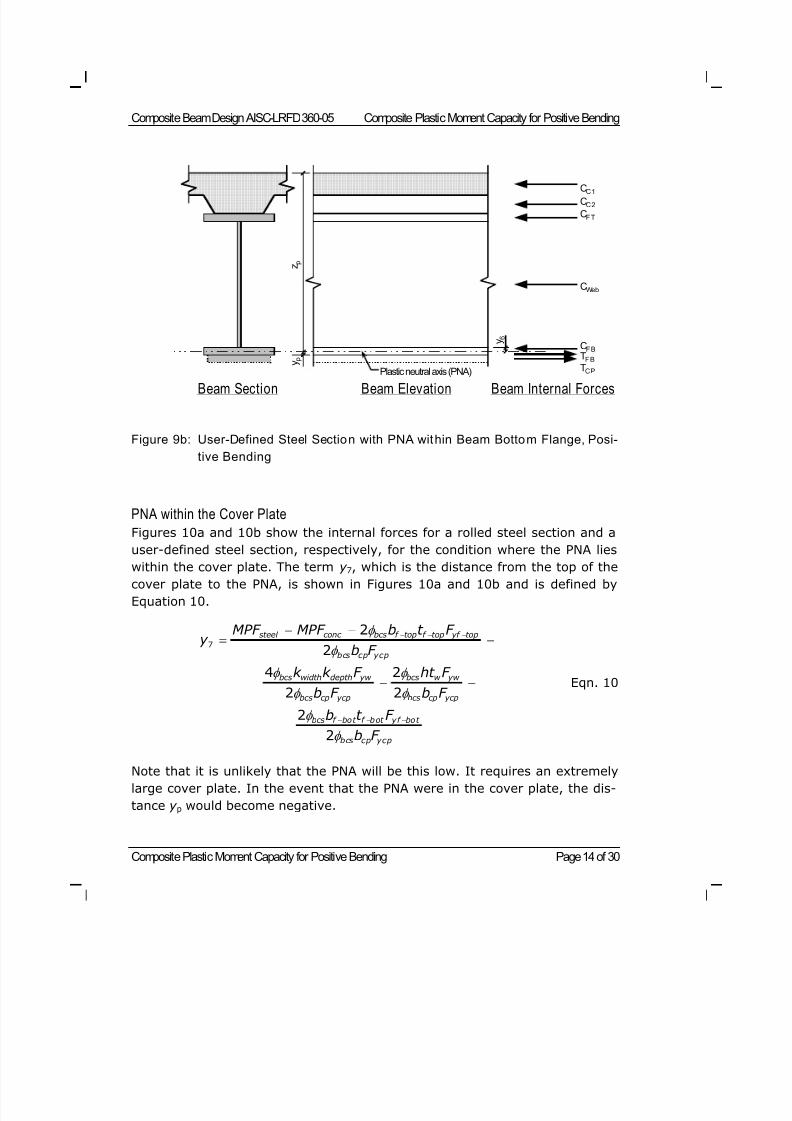
8/21/2019 Composit Beam
http://slidepdf.com/reader/full/composit-beam 74/161
Composite Beam Design AISC-LRFD 360-05 Composite Plastic Moment Capacity for Positive Bending
Composite Plastic Moment Capacity for Positive Bending Page 14 of 30
Figure 9b: User-Defined Steel Section with PNA within Beam Bottom Flange, Posi-
tive Bending
PNA within the Cover Plate
Figures 10a and 10b show the internal forces for a rolled steel section and a
user-defined steel section, respectively, for the condition where the PNA lies
within the cover plate. The term y 7, which is the distance from the top of the
cover plate to the PNA, is shown in Figures 10a and 10b and is defined by
Equation 10.
steel conc bcs f top f top yf top
bcs cp ycp
bcs width depth yw bcs w yw
bcs cp ycp bcs cp ycp
bcs f bot f bot yf bot
bcs cp ycp
MPF MPF b t F y
b F
k k F ht F
b F b F
b t F
b F
7
2
2
4 2
2 2
2
2
Eqn. 10
Note that it is unlikely that the PNA will be this low. It requires an extremely
large cover plate. In the event that the PNA were in the cover plate, the dis-
tance y p would become negative.
Beam Section Beam Elevation Beam Internal Forces
CC 1
CC 2
TF B
CF B
CWeb
TC P
CF T
y 6
Plastic neutral axis (PNA)
y p
z p
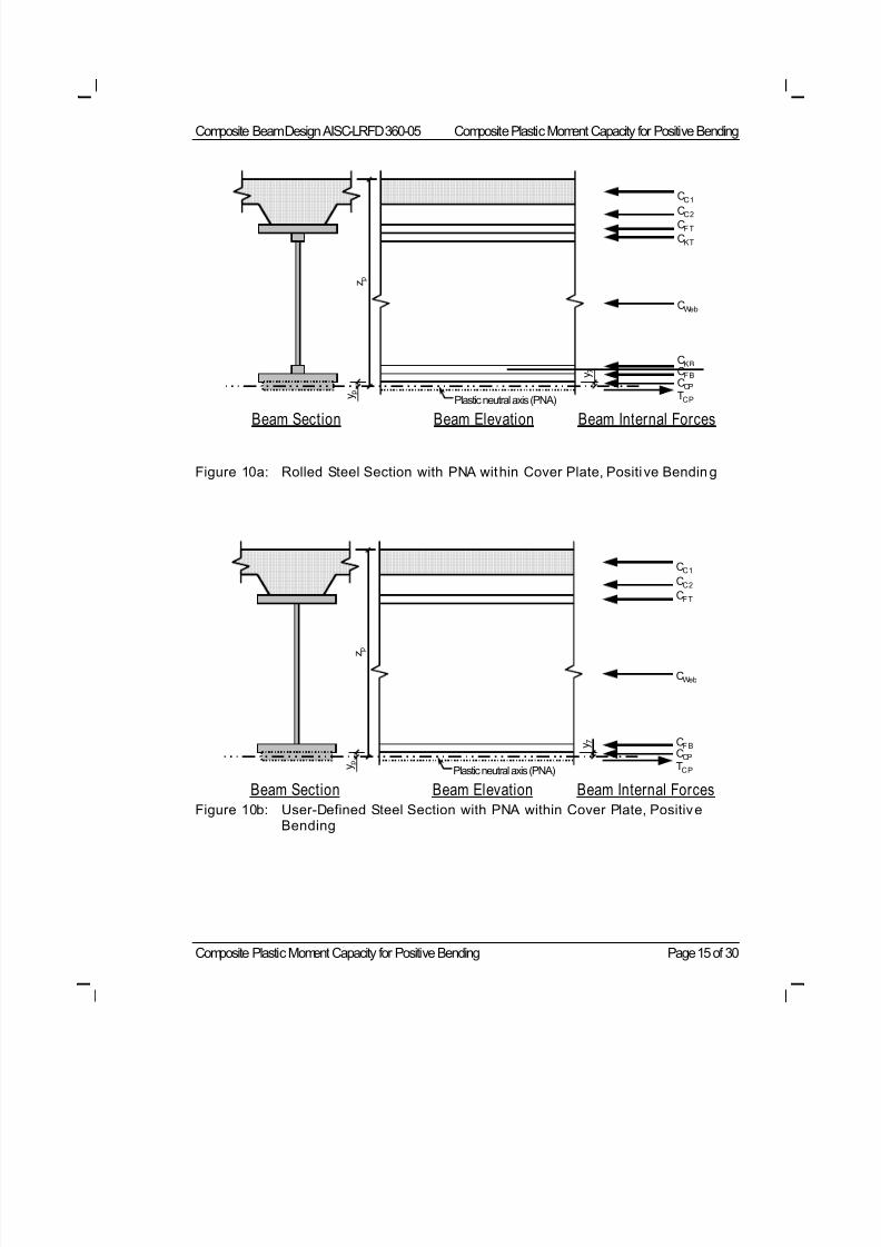
8/21/2019 Composit Beam
http://slidepdf.com/reader/full/composit-beam 75/161
Composite Beam Design AISC-LRFD 360-05 Composite Plastic Moment Capacity for Positive Bending
Composite Plastic Moment Capacity for Positive Bending Page 15 of 30
Figure 10a: Rolled Steel Section with PNA within Cover Plate, Positi ve Bending
Figure 10b: User-Defined Steel Section with PNA within Cover Plate, PositiveBending
CC 1
Beam Section Beam Elevation Beam Internal Forces
CC 2
CK T
CK B
CCP
CF B
CWeb
TC P
CF T
y 7
Plastic neutral axis (PNA) y p
z p
Beam Section Beam Elevation Beam Internal Forces
Plastic neutral axis (PNA)
CC 1
CC 2
CCP
CF B
CWeb
TC P
CF T
y 7
y p
z p
8/21/2019 Composit Beam
http://slidepdf.com/reader/full/composit-beam 76/161
Composite Beam Design AISC-LRFD 360-05 Composite Plastic Moment Capacity for Positive Bending
Composite Plastic Moment Capacity for Positive Bending Page 16 of 30
Calculating the PNA Location
To calculate the location of the PNA for positive bending, the program startsby comparing the value of MPF conc to that of MPF steel to determine if the PNA is
in the steel section or in the concrete slab above the steel section. As de-
scribed in an earlier section of this Technical Note, if MPF conc > MPF steel, the
PNA is within the concrete slab. If MPF steel > MPF conc, the PNA is within the
steel section. If MPF steel = MPF conc, the PNA is at the top of the steel beam.
If the PNA is in the concrete slab above the steel section, the procedure de-
scribed in the previous subsection of this Technical Note entitled "PNA in the
Concrete Slab Above the Steel Beam" is followed.
If the PNA is within the steel section, the program assumes that the PNA oc-
curs in the top flange of the beam. The distance y 2 is calculated using Equa-
tion 5. The calculated distance y 2 is then checked to see if it actually is within
the beam top flange. If it is, the location of the PNA has been identified.
If the calculated distance y 2 is not within the beam top flange, the program
continues by assuming that the PNA occurs in the beam top fillet. (Note that if
the beam is a user-defined beam, there is no top fillet and the program skips
directly to assuming that the PNA is in the beam web.) The distance y 3 is cal-
culated using Equation 6. The calculated distance y 3 is then checked to see if
it actually is within the beam top fillet. If it is, the location of the PNA has
been identified.
If the calculated distance y 3 is not within the beam top fillet, the program
continues by assuming that the PNA occurs in the beam web. The distance y 4
is calculated using Equation 7. The calculated distance y 4 is then checked to
see if it actually is within the beam web. If it is, the location of the PNA has
been identified.
In any practical case, the PNA is not expected to be below the beam web.
However, in the event the PNA has not yet been located, the program contin-
ues down the beam section through the bottom fillet, the bottom flange and
finally the cover plate until the location of the PNA has been identified.
Plastic Moment Capacity for Positive BendingThe plastic moment capacity for positive bending in a composite section is
calculated from Equation 11:
8/21/2019 Composit Beam
http://slidepdf.com/reader/full/composit-beam 77/161
Composite Beam Design AISC-LRFD 360-05 Composite Plastic Moment Capacity for Positive Bending
Composite Plastic Moment Capacity for Positive Bending Page 17 of 30
bcpp n bcpp piece PNA piece
Piece
bcpp piece PNA piece
Piece
M T x
C x
12
1
12
1
Eqn. 11
where:
C piece = Compression force in a piece of the composite beam,
kips.
M n = Plastic moment capacity for positive bending, kip-in.
T piece = Tension force in a piece of the composite beam, kips.
x PNA-piece = Distance from centroid of tension or compression force
in a piece of a composite beam to the PNA, in.
bcpp = Resistance factor for positive bending when plastic
stress distribution is assumed, unitless.
In Equation 11, the ten pieces are as follows:
Concrete above the metal deck, not including rebar, on the left side
of the beam: The concrete can carry only a compression force; tension is
not allowed in the concrete.
Concrete above the metal deck, not including rebar, on the right
side of the beam: The concrete can carry only a compression force; ten-
sion is not allowed in the concrete.
Concrete within the height of the metal deck on the left side of the
beam: The concrete can carry only a compression force; tension is not al-
lowed in the concrete.
Concrete within the height of the metal deck on the right side of the
beam: The concrete can carry only a compression force; tension is not al-
lowed in the concrete.
Beam top flange: The force in the beam top flange can be tension, com-
pression, or compression in the upper portion of the flange and tension in
the lower portion.
8/21/2019 Composit Beam
http://slidepdf.com/reader/full/composit-beam 78/161
Composite Beam Design AISC-LRFD 360-05 Composite Plastic Moment Capacity for Positive Bending
Composite Plastic Moment Capacity for Positive Bending Page 18 of 30
Beam top fillet: The force in the beam top fillet can be tension, compres-
sion, or compression in the upper portion of the fillet and tension in thelower portion.
Beam web: The force in the beam web can be tension, compression, or
compression in the upper portion of the web and tension in the lower por-
tion.
Beam bottom fillet: The force in the beam bottom fillet can be tension,
compression, or compression in the upper portion of the fillet and tension in
the lower portion.
Beam bottom flange: The force in the beam bottom flange can be ten-
sion, compression, or compression in the upper portion of the flange andtension in the lower portion.
Cover plate: The force in the cover plate can be tension, or compression in
the upper portion of the cover plate and tension in the lower portion.
In Equation 11 the values used for T piece, C piece and x PNA-piece depend on the lo-
cation of the PNA. The appropriate values for these items are given in Tables
2 through 11. Table 1 serves as a guide to which of those tables to use based
on the location of the PNA.
Note, because the metal deck and concrete slab can be in different locations
relative to the PNA on the two sides of the beam, you may need to use valuesfrom two different tables listed in Table 1.
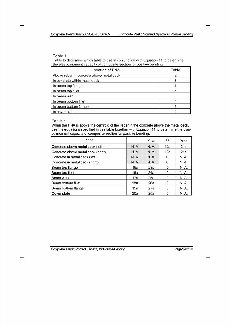
8/21/2019 Composit Beam
http://slidepdf.com/reader/full/composit-beam 79/161
Composite Beam Design AISC-LRFD 360-05 Composite Plastic Moment Capacity for Positive Bending
Composite Plastic Moment Capacity for Positive Bending Page 19 of 30
Table 1:Table to determine which table to use in conjunction with Equation 11 to determinethe plastic moment capacity of composite section for positive bending.
Location of PNA Table
Above rebar in concrete above metal deck 2
In concrete within metal deck 3
In beam top flange 4
In beam top fillet 5
In beam web 6
In beam bottom fillet 7
In beam bottom flange 8
In cover plate 9
Table 2:When the PNA is above the centroid of the rebar in the concrete above the metal deck,use the equations specified in this table together with Equation 11 to determine the plas-tic moment capacity of composite section for positive bending.
Piece T xPNA C xPNA
Concrete above metal deck (left) N. A. N. A. 12a 21a
Concrete above metal deck (right) N. A. N. A. 12a 21a
Concrete in metal deck (left) N. A. N. A. 0 N. A.
Concrete in metal deck (right) N. A. N. A. 0 N. A.Beam top flange 15a 23a 0 N. A.
Beam top fillet 16a 24a 0 N. A.
Beam web 17a 25a 0 N. A.
Beam bottom fillet 18a 26a 0 N. A.
Beam bottom flange 19a 27a 0 N. A.
Cover plate 20a 28a 0 N. A.
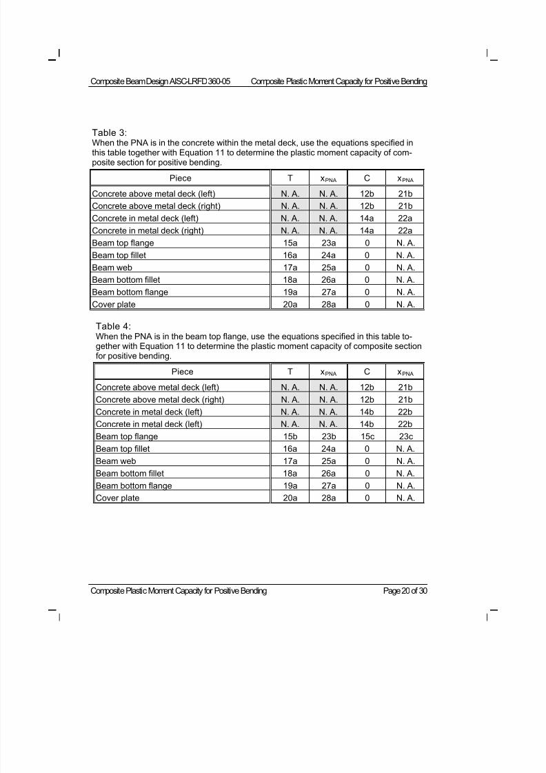
8/21/2019 Composit Beam
http://slidepdf.com/reader/full/composit-beam 80/161
Composite Beam Design AISC-LRFD 360-05 Composite Plastic Moment Capacity for Positive Bending
Composite Plastic Moment Capacity for Positive Bending Page 20 of 30
Table 3:When the PNA is in the concrete within the metal deck, use the equations specified inthis table together with Equation 11 to determine the plastic moment capacity of com-posite section for positive bending.
Piece T xPNA C xPNA
Concrete above metal deck (left) N. A. N. A. 12b 21b
Concrete above metal deck (right) N. A. N. A. 12b 21b
Concrete in metal deck (left) N. A. N. A. 14a 22a
Concrete in metal deck (right) N. A. N. A. 14a 22a
Beam top flange 15a 23a 0 N. A.
Beam top fillet 16a 24a 0 N. A.Beam web 17a 25a 0 N. A.
Beam bottom fillet 18a 26a 0 N. A.
Beam bottom flange 19a 27a 0 N. A.
Cover plate 20a 28a 0 N. A.
Table 4:When the PNA is in the beam top flange, use the equations specified in this table to-gether with Equation 11 to determine the plastic moment capacity of composite sectionfor positive bending.
Piece T xPNA C xPNA
Concrete above metal deck (left) N. A. N. A. 12b 21bConcrete above metal deck (right) N. A. N. A. 12b 21b
Concrete in metal deck (left) N. A. N. A. 14b 22b
Concrete in metal deck (left) N. A. N. A. 14b 22b
Beam top flange 15b 23b 15c 23c
Beam top fillet 16a 24a 0 N. A.
Beam web 17a 25a 0 N. A.
Beam bottom fillet 18a 26a 0 N. A.
Beam bottom flange 19a 27a 0 N. A.
Cover plate 20a 28a 0 N. A.
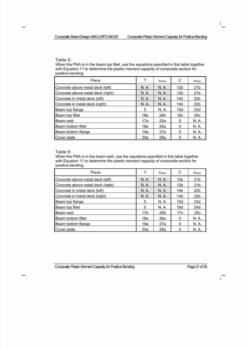
8/21/2019 Composit Beam
http://slidepdf.com/reader/full/composit-beam 81/161
Composite Beam Design AISC-LRFD 360-05 Composite Plastic Moment Capacity for Positive Bending
Composite Plastic Moment Capacity for Positive Bending Page 21 of 30
Table 5:When the PNA is in the beam top fillet, use the equations specified in this table togetherwith Equation 11 to determine the plastic moment capacity of composite section forpositive bending.
Piece T xPNA C xPNA
Concrete above metal deck (left) N. A. N. A. 12b 21b
Concrete above metal deck (right) N. A. N. A. 12b 21b
Concrete in metal deck (left) N. A. N. A. 14b 22b
Concrete in metal deck (right) N. A. N. A. 14b 22b
Beam top flange 0 N. A. 15d 23d
Beam top fillet 16b 24b 16c 24cBeam web 17a 25a 0 N. A.
Beam bottom fillet 18a 26a 0 N. A.
Beam bottom flange 19a 27a 0 N. A.
Cover plate 20a 28a 0 N. A.
Table 6:When the PNA is in the beam web, use the equations specified in this table togetherwith Equation 11 to determine the plastic moment capacity of composite section forpositive bending.
Piece T xPNA C xPNA
Concrete above metal deck (left) N. A. N. A. 12b 21b
Concrete above metal deck (right) N. A. N. A. 12b 21b
Concrete in metal deck (left) N. A. N. A. 14b 22b
Concrete in metal deck (right) N. A. N. A. 14b 22b
Beam top flange 0 N. A. 15d 23d
Beam top fillet 0 N. A. 16d 24d
Beam web 17b 25b 17c 25c
Beam bottom fillet 18a 26a 0 N. A.
Beam bottom flange 19a 27a 0 N. A.
Cover plate 20a 28a 0 N. A.
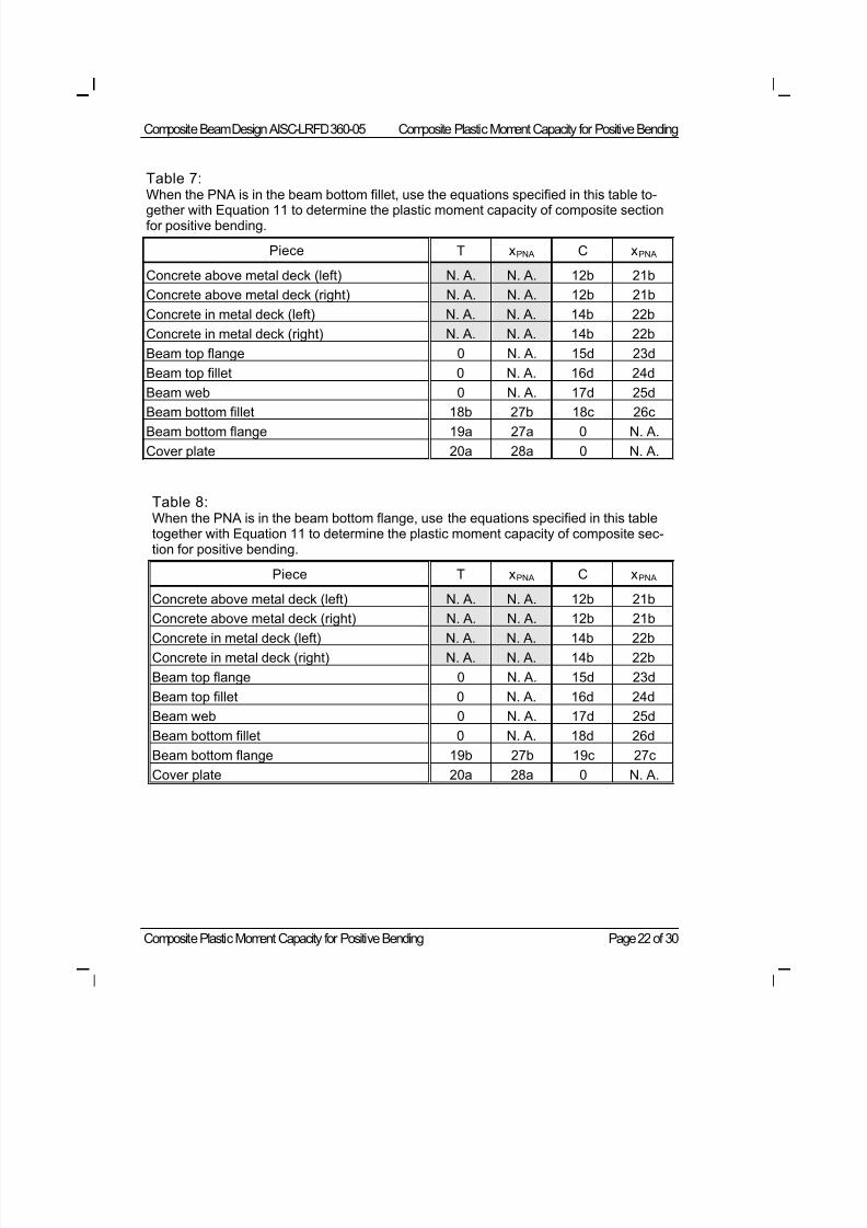
8/21/2019 Composit Beam
http://slidepdf.com/reader/full/composit-beam 82/161
Composite Beam Design AISC-LRFD 360-05 Composite Plastic Moment Capacity for Positive Bending
Composite Plastic Moment Capacity for Positive Bending Page 22 of 30
Table 7:When the PNA is in the beam bottom fillet, use the equations specified in this table to-
gether with Equation 11 to determine the plastic moment capacity of composite sectionfor positive bending.
Piece T xPNA C xPNA
Concrete above metal deck (left) N. A. N. A. 12b 21b
Concrete above metal deck (right) N. A. N. A. 12b 21b
Concrete in metal deck (left) N. A. N. A. 14b 22b
Concrete in metal deck (right) N. A. N. A. 14b 22b
Beam top flange 0 N. A. 15d 23d
Beam top fillet 0 N. A. 16d 24d
Beam web 0 N. A. 17d 25d
Beam bottom fillet 18b 27b 18c 26cBeam bottom flange 19a 27a 0 N. A.
Cover plate 20a 28a 0 N. A.
Table 8:When the PNA is in the beam bottom flange, use the equations specified in this tabletogether with Equation 11 to determine the plastic moment capacity of composite sec-tion for positive bending.
Piece T xPNA C xPNA
Concrete above metal deck (left) N. A. N. A. 12b 21b
Concrete above metal deck (right) N. A. N. A. 12b 21bConcrete in metal deck (left) N. A. N. A. 14b 22b
Concrete in metal deck (right) N. A. N. A. 14b 22b
Beam top flange 0 N. A. 15d 23d
Beam top fillet 0 N. A. 16d 24d
Beam web 0 N. A. 17d 25d
Beam bottom fillet 0 N. A. 18d 26d
Beam bottom flange 19b 27b 19c 27c
Cover plate 20a 28a 0 N. A.
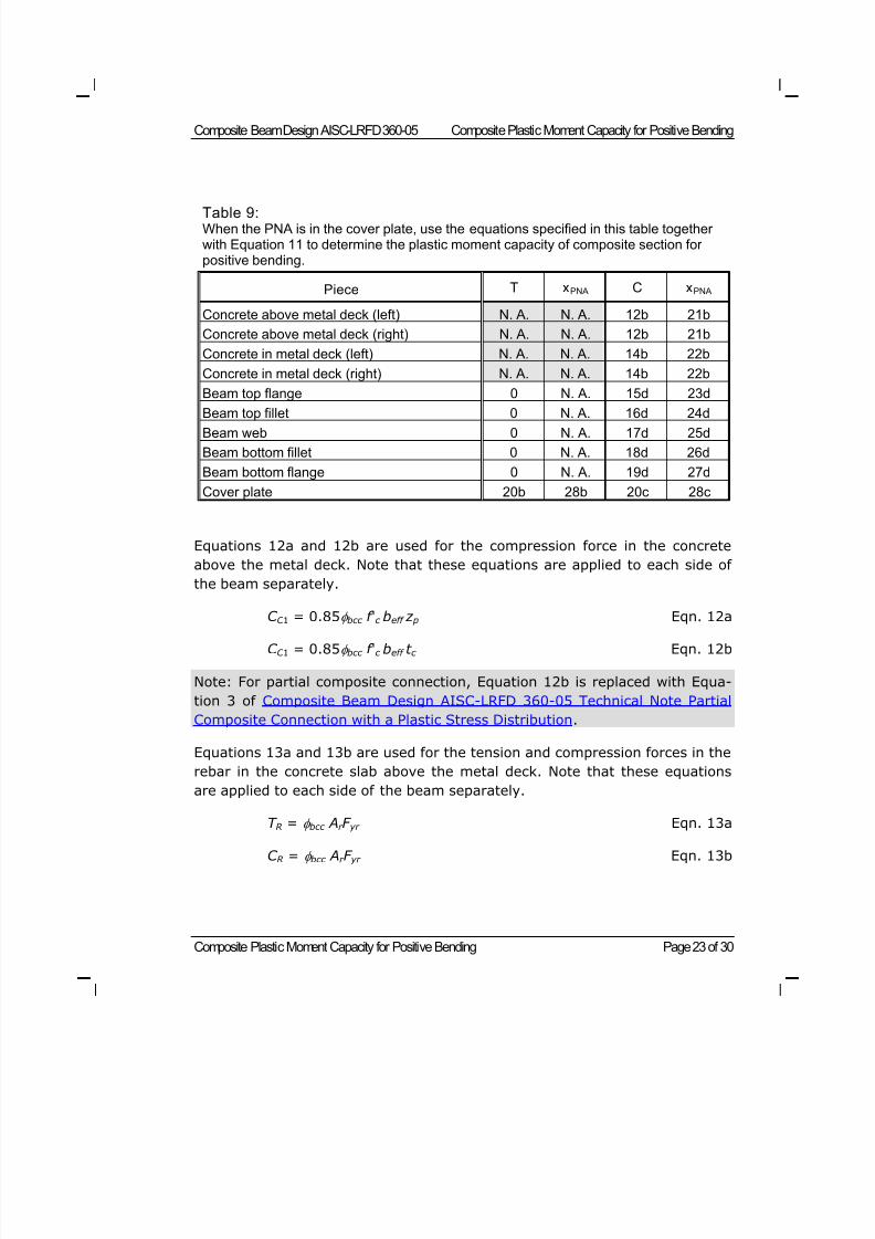
8/21/2019 Composit Beam
http://slidepdf.com/reader/full/composit-beam 83/161
Composite Beam Design AISC-LRFD 360-05 Composite Plastic Moment Capacity for Positive Bending
Composite Plastic Moment Capacity for Positive Bending Page 23 of 30
Table 9:When the PNA is in the cover plate, use the equations specified in this table togetherwith Equation 11 to determine the plastic moment capacity of composite section forpositive bending.
Piece T xPNA C xPNA
Concrete above metal deck (left) N. A. N. A. 12b 21b
Concrete above metal deck (right) N. A. N. A. 12b 21b
Concrete in metal deck (left) N. A. N. A. 14b 22b
Concrete in metal deck (right) N. A. N. A. 14b 22b
Beam top flange 0 N. A. 15d 23d
Beam top fillet 0 N. A. 16d 24dBeam web 0 N. A. 17d 25d
Beam bottom fillet 0 N. A. 18d 26d
Beam bottom flange 0 N. A. 19d 27d
Cover plate 20b 28b 20c 28c
Equations 12a and 12b are used for the compression force in the concrete
above the metal deck. Note that these equations are applied to each side of
the beam separately.
C C 1 = 0.85 bcc f 'c beff z p Eqn. 12a
C C 1 = 0.85 bcc f 'c beff t c Eqn. 12b
Note: For partial composite connection, Equation 12b is replaced with Equa-
tion 3 of Composite Beam Design AISC-LRFD 360-05 Technical Note Partial
Composite Connection with a Plastic Stress Distribution.
Equations 13a and 13b are used for the tension and compression forces in the
rebar in the concrete slab above the metal deck. Note that these equations
are applied to each side of the beam separately.
T R =
bcc A
r F
yr Eqn. 13a
C R = bcc Ar F yr Eqn. 13b
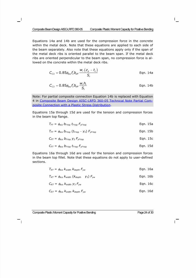
8/21/2019 Composit Beam
http://slidepdf.com/reader/full/composit-beam 84/161
Composite Beam Design AISC-LRFD 360-05 Composite Plastic Moment Capacity for Positive Bending
Composite Plastic Moment Capacity for Positive Bending Page 24 of 30
Equations 14a and 14b are used for the compression force in the concrete
within the metal deck. Note that these equations are applied to each side ofthe beam separately. Also note that these equations apply only if the span of
the metal deck ribs is oriented parallel to the beam span. If the metal deck
ribs are oriented perpendicular to the beam span, no compression force is al-
lowed on the concrete within the metal deck ribs.
r p c ' C bcc c eff
r
w z t C . f b
S
2 0 85 Eqn. 14a
' r r C bcc c eff
r
w hC . f b
S 2 0 85 Eqn. 14b
Note: For partial composite connection Equation 14b is replaced with Equation
4 in Composite Beam Design AISC-LRFD 360-05 Technical Note Partial Com-
posite Connection with a Plastic Stress Distribution.
Equations 15a through 15d are used for the tension and compression forces
in the beam top flange.
T FT = bcs bf -top t f -top F yf -top Eqn. 15a
T FT = bcs bf -top (t f -top y 2) F yf -top Eqn. 15b
C FT = bcs bf -top y 2 F yf -top Eqn. 15c
C FT = bcs bf -top t f -top F yf -top Eqn. 15d
Equations 16a through 16d are used for the tension and compression forces
in the beam top fillet. Note that these equations do not apply to user-defined
sections.
T KT = bcs k width k depth F yw Eqn. 16a
T KT = bcs k width (k depth y 3) F yw Eqn. 16b
C KT = bcs k width y 3 F yw Eqn. 16c
C KT = bcs k width k depth F yw Eqn. 16d
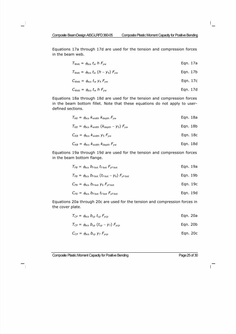
8/21/2019 Composit Beam
http://slidepdf.com/reader/full/composit-beam 85/161
Composite Beam Design AISC-LRFD 360-05 Composite Plastic Moment Capacity for Positive Bending
Composite Plastic Moment Capacity for Positive Bending Page 25 of 30
Equations 17a through 17d are used for the tension and compression forces
in the beam web.
T Web = bcs t w h F yw Eqn. 17a
T Web = bcs t w (h y 4) F yw Eqn. 17b
C Web = bcs t w y 4 F yw Eqn. 17c
C Web = bcs t w h F yw Eqn. 17d
Equations 18a through 18d are used for the tension and compression forces
in the beam bottom fillet. Note that these equations do not apply to user-
defined sections.
T KB = bcs k width k depth F yw Eqn. 18a
T KB = bcs k width (k depth y 5) F yw Eqn. 18b
C KB = bcs k width y 5 F yw Eqn. 18c
C KB = bcs k width k depth F yw Eqn. 18d
Equations 19a through 19d are used for the tension and compression forces
in the beam bottom flange.
T FB = bcs bf -bot t f -bot F yf -bot Eqn. 19a
T FB = bcs bf -bot (t f -bot y 6) F yf -bot Eqn. 19b
C FB = bcs bf -bot y 6 F yf -bot Eqn. 19c
C FB = bcs bf -bot t f -bot F yf -bot Eqn. 19d
Equations 20a through 20c are used for the tension and compression forces in
the cover plate.
T CP = bcs bcp t cp F ycp Eqn. 20a
T CP = bcs bcp (t cp y 7) F ycp Eqn. 20b
C CP = bcs bcp y 7 F ycp Eqn. 20c
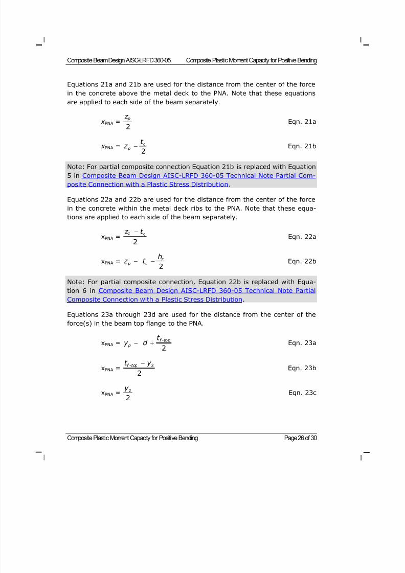
8/21/2019 Composit Beam
http://slidepdf.com/reader/full/composit-beam 86/161
Composite Beam Design AISC-LRFD 360-05 Composite Plastic Moment Capacity for Positive Bending
Composite Plastic Moment Capacity for Positive Bending Page 26 of 30
Equations 21a and 21b are used for the distance from the center of the force
in the concrete above the metal deck to the PNA. Note that these equationsare applied to each side of the beam separately.
x PNA = z
2 Eqn. 21a
x PNA =c
p
t z
2 Eqn. 21b
Note: For partial composite connection Equation 21b is replaced with Equation
5 in Composite Beam Design AISC-LRFD 360-05 Technical Note Partial Com-
posite Connection with a Plastic Stress Distribution.
Equations 22a and 22b are used for the distance from the center of the force
in the concrete within the metal deck ribs to the PNA. Note that these equa-
tions are applied to each side of the beam separately.
xPNA =c z t
2 Eqn. 22a
xPNA =r
p c
h z t
2 Eqn. 22b
Note: For partial composite connection, Equation 22b is replaced with Equa-
tion 6 in Composite Beam Design AISC-LRFD 360-05 Technical Note Partial
Composite Connection with a Plastic Stress Distribution.
Equations 23a through 23d are used for the distance from the center of the
force(s) in the beam top flange to the PNA.
xPNA =f -top
p
t y d
2 Eqn. 23a
xPNA =f -topt y 2
2 Eqn. 23b
xPNA =y 22
Eqn. 23c
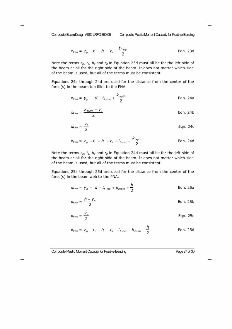
8/21/2019 Composit Beam
http://slidepdf.com/reader/full/composit-beam 87/161
Composite Beam Design AISC-LRFD 360-05 Composite Plastic Moment Capacity for Positive Bending
Composite Plastic Moment Capacity for Positive Bending Page 27 of 30
xPNA =f top
p c r d
t z t h r
2
Eqn. 23d
Note the terms z p, t c , hr and r d in Equation 23d must all be for the left side of
the beam or all for the right side of the beam. It does not matter which side
of the beam is used, but all of the terms must be consistent.
Equations 24a through 24d are used for the distance from the center of the
force(s) in the beam top fillet to the PNA.
xPNA =depth
p f top
k y d t
2 Eqn. 24a
xPNA =depthk y 3
2 Eqn. 24b
xPNA =y 32
Eqn. 24c
xPNA =depth
p c r d f top
k z t h r t
2 Eqn. 24d
Note the terms z p, t c , hr and r d in Equation 24d must all be for the left side of
the beam or all for the right side of the beam. It does not matter which side
of the beam is used, but all of the terms must be consistent.
Equations 25a through 25d are used for the distance from the center of the
force(s) in the beam web to the PNA.
xPNA = p f top depth
hy d t k
2 Eqn. 25a
xPNA =h y 4
2 Eqn. 25b
xPNA =y 4
2
Eqn. 25c
xPNA = p c r d f top depth
h z t h r t k
2 Eqn. 25d
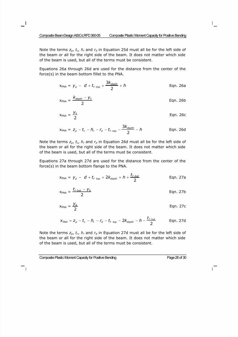
8/21/2019 Composit Beam
http://slidepdf.com/reader/full/composit-beam 88/161
Composite Beam Design AISC-LRFD 360-05 Composite Plastic Moment Capacity for Positive Bending
Composite Plastic Moment Capacity for Positive Bending Page 28 of 30
Note the terms z p, t c , hr and r d in Equation 25d must all be for the left side of
the beam or all for the right side of the beam. It does not matter which sideof the beam is used, but all of the terms must be consistent.
Equations 26a through 26d are used for the distance from the center of the
force(s) in the beam bottom fillet to the PNA.
xPNA =depth
p f top
k y d t h
3
2 Eqn. 26a
xPNA =depthk y 5
2 Eqn. 26b
xPNA = y 52
Eqn. 26c
xPNA =depth
p c r d f top
k z t h r t h
3
2 Eqn. 26d
Note the terms z p, t c , hr and r d in Equation 26d must all be for the left side of
the beam or all for the right side of the beam. It does not matter which side
of the beam is used, but all of the terms must be consistent.
Equations 27a through 27d are used for the distance from the center of the
force(s) in the beam bottom flange to the PNA.
xPNA =f -bot
p f top depth
t y d t k h 2
2 Eqn. 27a
xPNA =f -bot t y 6
2 Eqn. 27b
xPNA =y 62
Eqn. 27c
f -bot PNA p c r d f top depth
t x z t h r t k h 2
2 Eqn. 27d
Note the terms z p, t c , hr and r d in Equation 27d must all be for the left side of
the beam or all for the right side of the beam. It does not matter which side
of the beam is used, but all of the terms must be consistent.
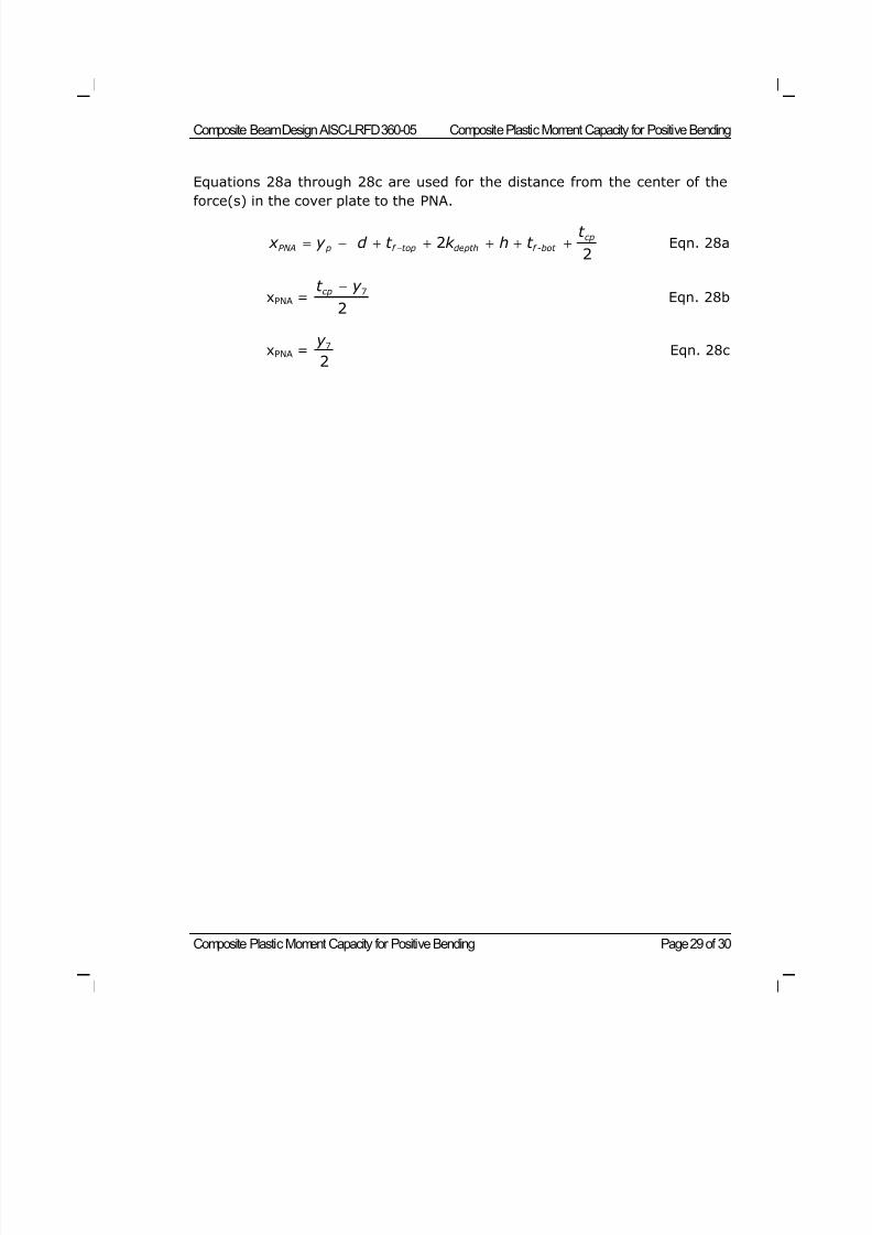
8/21/2019 Composit Beam
http://slidepdf.com/reader/full/composit-beam 89/161
Composite Beam Design AISC-LRFD 360-05 Composite Plastic Moment Capacity for Positive Bending
Composite Plastic Moment Capacity for Positive Bending Page 29 of 30
Equations 28a through 28c are used for the distance from the center of the
force(s) in the cover plate to the PNA.
cp
PNA p f top depth f -bot
t x y d t k h t 2
2 Eqn. 28a
xPNA =cpt y 7
2 Eqn. 28b
xPNA =y 72
Eqn. 28c

8/21/2019 Composit Beam
http://slidepdf.com/reader/full/composit-beam 90/161
8/21/2019 Composit Beam
http://slidepdf.com/reader/full/composit-beam 91/161
Composite Section Elastic Moment Capacity Page 1 of 3
©COMPUTERS AND STRUCTURES, INC., BERKELEY, C ALIFORNIA JUNE 2009
COMPOSITEBEAMDESIGN AISC-LRFD 360-05
Technical Note
Composite Section Elastic Moment Capacity
This Technical Note describes how the program calculates the moment capac-
ity of a composite section when an elastic stress distribution is assumed.
Positive Moment Capacity with an Elastic StressDistribution
To calculate the positive moment capacity with an elastic stress distribution,the program first calculates the location of the elastic neutral axis (ENA) and
the transformed section moment of inertia. Information on how the program
calculates the location of the ENA and the transformed section moment of in-
ertia for full composite connection is provided in Composite Beam Design
AISC-ASD89 Technical Note Transformed Section Moment of Inertia. Informa-
tion on how the program calculates the location of the ENA and the trans-
formed section moment of inertia for partial composite connection is provided
in Composite Beam Design AISC-ASD89 Technical Note Elastic Stresses with
Partial Composite Connection.
The positive moment capacity for a composite beam with an elastic stress dis-tribution is determined by considering five locations in the composite section.
These locations are as follows:
The top of the concrete on the left side of the beam.
The top of the concrete on the right side of the beam.
The top of the top flange of the beam.
The bottom of the bottom flange of the beam.
The bottom of the cover plate.
A moment capacity is calculated based on the allowable stress and the section
modulus at each of these five locations that is applicable to the beam consid-
ered. The smallest moment capacity calculated is the positive moment capac-
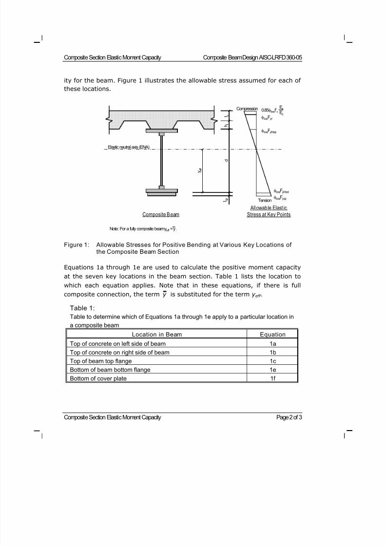
8/21/2019 Composit Beam
http://slidepdf.com/reader/full/composit-beam 92/161
Composite Section Elastic Moment Capacity Composite Beam Design AISC-LRFD 360-05
Composite Section Elastic Moment Capacity Page 2 of 3
ity for the beam. Figure 1 illustrates the allowable stress assumed for each of
these locations.
Figure 1: Allowable Stresses for Positive Bending at Various Key Locations ofthe Composite Beam Section
Equations 1a through 1e are used to calculate the positive moment capacity
at the seven key locations in the beam section. Table 1 lists the location to
which each equation applies. Note that in these equations, if there is full
composite connection, the term y is substituted for the term y eff .
Table 1:
Table to determine which of Equations 1a through 1e apply to a particular location in
a composite beam Location in Beam Equation
Top of concrete on left side of beam 1a
Top of concrete on right side of beam 1b
Top of beam top flange 1c
Bottom of beam bottom flange 1e
Bottom of cover plate 1f
h r
t c
d
t c p
y e f f
Elastic neutral axis (ENA)
bcsFycp
bcsFyf-bot
bcsFyf-top
bccFyr
0.85bccf’cEs
Ec
Composite B eam
All owable Elast ic
Stress at Key Points
Compression
Tension
Note: For a fully composite beam yeff = y.
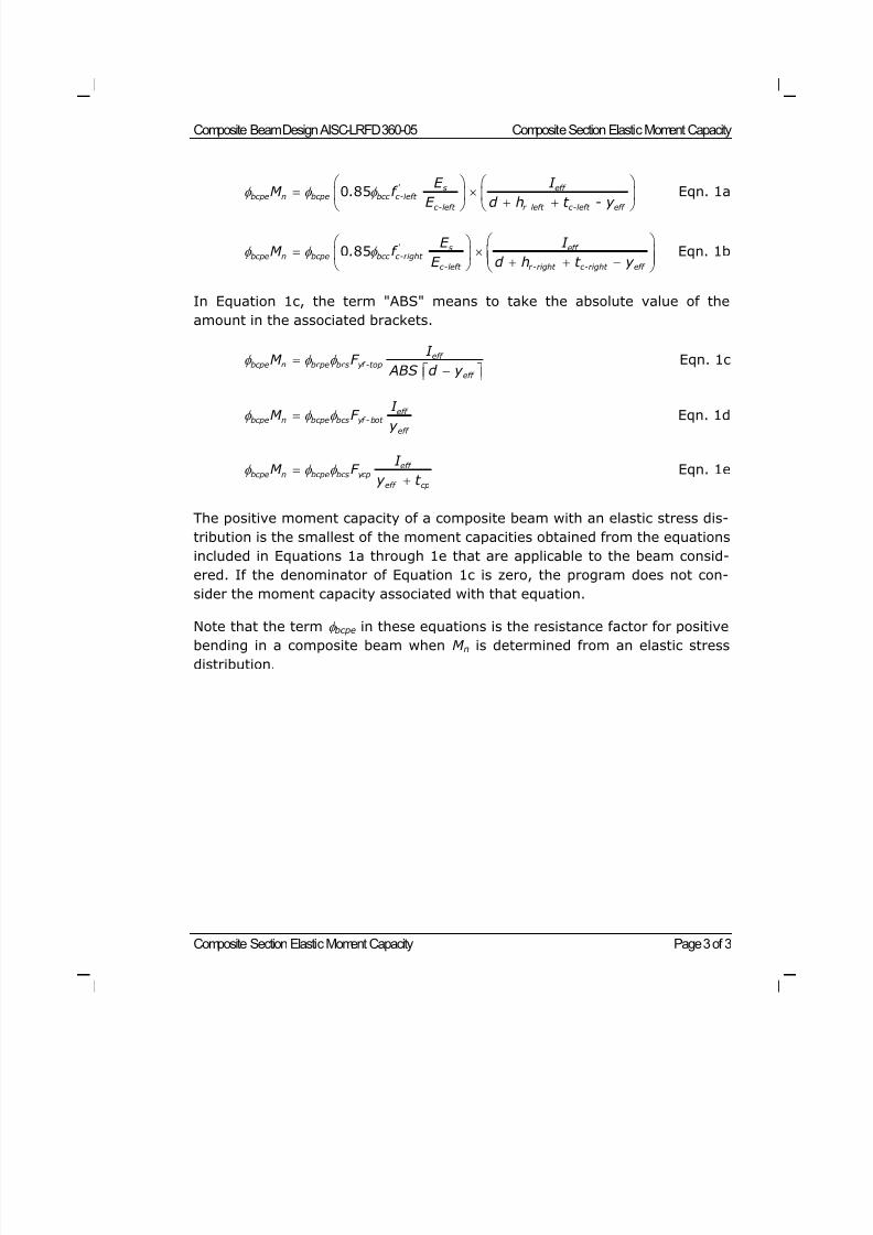
8/21/2019 Composit Beam
http://slidepdf.com/reader/full/composit-beam 93/161
Composite Beam Design AISC-LRFD 360-05 Composite Section Elastic Moment Capacity
Composite Section Elastic Moment Capacity Page 3 of 3
' s eff bcpe n bcpe bcc c-left
c-left r -left c-left eff
E I M . f
E d h t - y
0 85 Eqn. 1a
' s eff bcpe n bcpe bcc c-right
c-left r-right c-right eff
E I M . f
E d h t y
0 85 Eqn. 1b
In Equation 1c, the term "ABS" means to take the absolute value of the
amount in the associated brackets.
eff bcpe n bcpe bcs yf -top
eff
I M F
ABS d y
Eqn. 1c
eff bcpe n bcpe bcs yf - bot
eff
I M F y
Eqn. 1d
eff bcpe n bcpe bcs ycp
eff cp
I M F
y t
Eqn. 1e
The positive moment capacity of a composite beam with an elastic stress dis-
tribution is the smallest of the moment capacities obtained from the equations
included in Equations 1a through 1e that are applicable to the beam consid-
ered. If the denominator of Equation 1c is zero, the program does not con-
sider the moment capacity associated with that equation.
Note that the term bcpe in these equations is the resistance factor for positive
bending in a composite beam when M n is determined from an elastic stress
distribution.
8/21/2019 Composit Beam
http://slidepdf.com/reader/full/composit-beam 94/161
Moment Capacity for Steel Section Alone Page 1 of 20
©COMPUTERS AND STRUCTURES, INC., BERKELEY, C ALIFORNIA JUNE 2009
COMPOSITEBEAMDESIGN AISC-LRFD 360-05
Technical Note
Moment Capacity for Steel Section Alone
This Technical Note describes how the program calculates the moment capac-
ity of a noncomposite steel beam, including a cover plate, if applicable.
Overview
The program calculates the moment capacity, M n, only if the beam is compact
or noncompact. It does not calculate M n if the section is slender.
The plastic moment, M p, for a noncomposite rolled steel beam section without
a cover plate is calculated as M p = ZF y .
The exact methodology used to compute the plastic moment capacity in the
other cases depends on whether the beam, including the cover plate if it ex-
ists, is doubly or singly symmetric, and whether the beam web is classified as
compact or noncompact.
Figure 1 shows a flowchart that identifies the appropriate section in this tech-
nical note for calculating the moment capacity of the steel section alone. The
figure has boxes labeled a through g; start in the box labeled a. Note that thecriteria used by the program to determine if a section is compact or noncom-
pact for the AISC-LRFD 360-05 specification is described in Composite Beam
Design AISC-LRFD 360-05 Technical Note Compact and Noncompact Re-
quirements.
Steel Beam Properties
If properties for the steel section alone are available directly from the pro-
gram's section database, those properties are used to compute the moment
capacity. For other cases, such as a user-defined section or a section with a
cover plate, the section properties are calculated in a manner similar to thatdescribed in Composite Beam Design AISC-ASD89 Technical Note Trans-
formed Section Moment of Inertia, except that there is no concrete or rein-
forcing steel to consider.
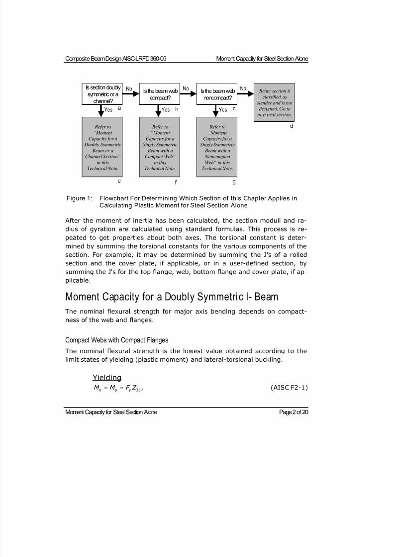
8/21/2019 Composit Beam
http://slidepdf.com/reader/full/composit-beam 95/161
Composite Beam Design AISC-LRFD 360-05 Moment Capacity for Steel Section Alone
Moment Capacity for Steel Section Alone Page 2 of 20
After the moment of inertia has been calculated, the section moduli and ra-
dius of gyration are calculated using standard formulas. This process is re-
peated to get properties about both axes. The torsional constant is deter-
mined by summing the torsional constants for the various components of the
section. For example, it may be determined by summing the J's of a rolled
section and the cover plate, if applicable, or in a user-defined section, by
summing the J's for the top flange, web, bottom flange and cover plate, if ap-
plicable.
Moment Capacity for a Doubly Symmetric I- Beam
The nominal flexural strength for major axis bending depends on compact-
ness of the web and flanges.
Compact Webs with Compact Flanges
The nominal flexural strength is the lowest value obtained according to the
limit states of yielding (plastic moment) and lateral-torsional buckling.
Yielding
n p y M M F Z 33, (AISC F2-1)
Is section doubly
symmetric or achannel?
Yes
No
Refer to
“Moment
Capacity for a
Doubly Symmetric
Beam or a
Channel Section”
in this
Technical Note.
Is the beam webcompact?
Yes
No
Is the beam webnoncompact?
Yes
No Beam section isclassified as
slender and is not
designed. Go to
next trial section.
Refer to
“Moment
Capacity for a
Singly Symmetric
Beam with a
Compact Web”
in this
Technical Note.
Refer to
“Moment
Capacity for a
Singly Symmetric
Beam with a
Noncompact
Web” in this
Technical Note.
a b c
d
e f g
Figure 1: Flowchart For Determining Which Section of this Chapter Applies inCalculating Plastic Moment for Steel Section Alone
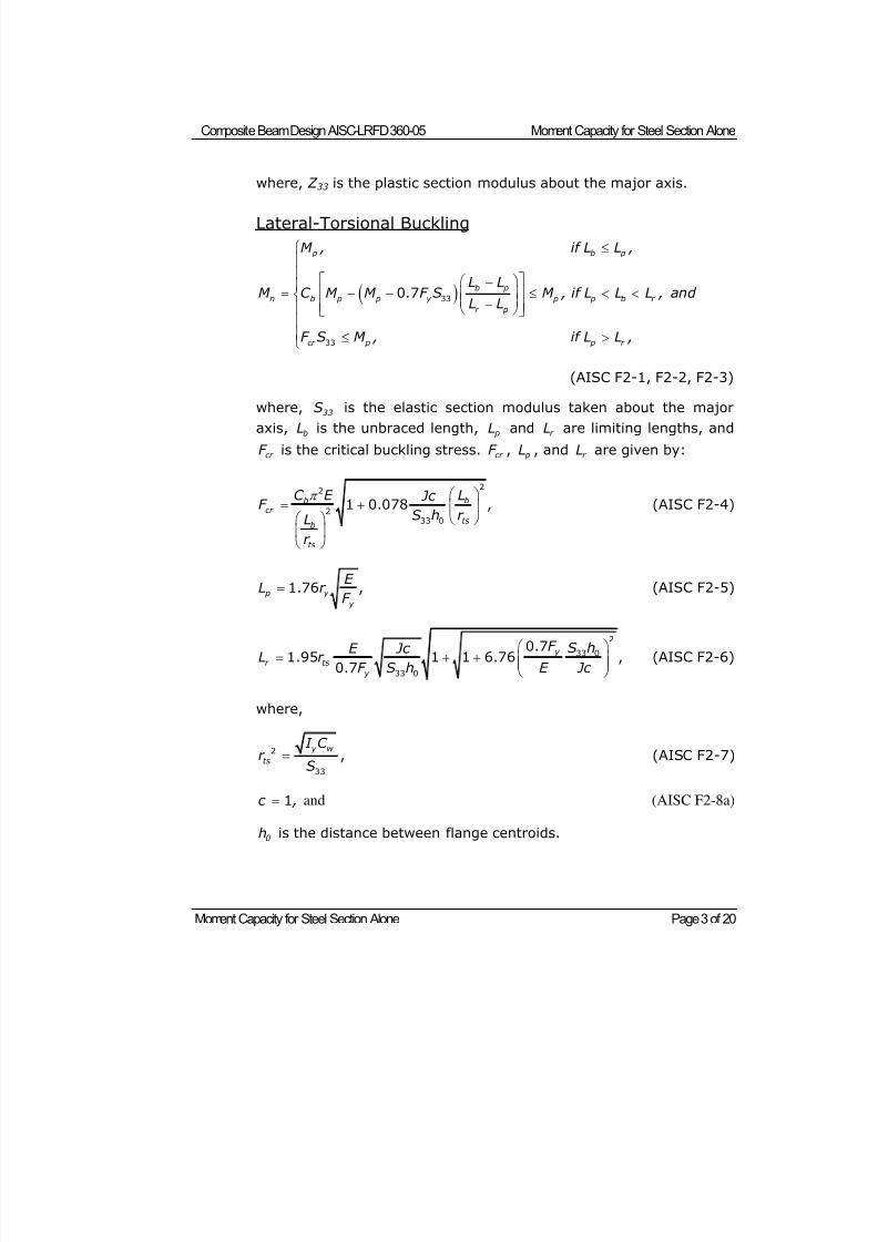
8/21/2019 Composit Beam
http://slidepdf.com/reader/full/composit-beam 96/161
Composite Beam Design AISC-LRFD 360-05 Moment Capacity for Steel Section Alone
Moment Capacity for Steel Section Alone Page 3 of 20
where, Z 33 is the plastic section modulus about the major axis.
Lateral-Torsional Buckling
p b p
b p
n b p p y p p b r
r p
cr p p r
M , if L L ,
L LM C M M . F S M , if L L L , and
L L
F S M , if L L ,
33
33
0 7
(AISC F2-1, F2-2, F2-3)
where,33
S is the elastic section modulus taken about the major
axis, bL is the unbraced length, pL and r L are limiting lengths, and
cr F is the critical buckling stress. cr F , pL , and r L are given by:
b bcr
tsb
ts
C E L Jc F
S h r L
r
22
233 0
1 0.078 , (AISC F2-4)
p y
y
E L r
F 1.76 , (AISC F2-5)
y
r ts
y
F S hE Jc L r
F S h E Jc
2
33 0
33 0
0.71.95 1 1 6.76 ,
0.7 (AISC F2-6)
where,
y w
ts
I C r
S2
33
, (AISC F2-7)
c , 1 and (AISC F2-8a)
0h is the distance between flange centroids.
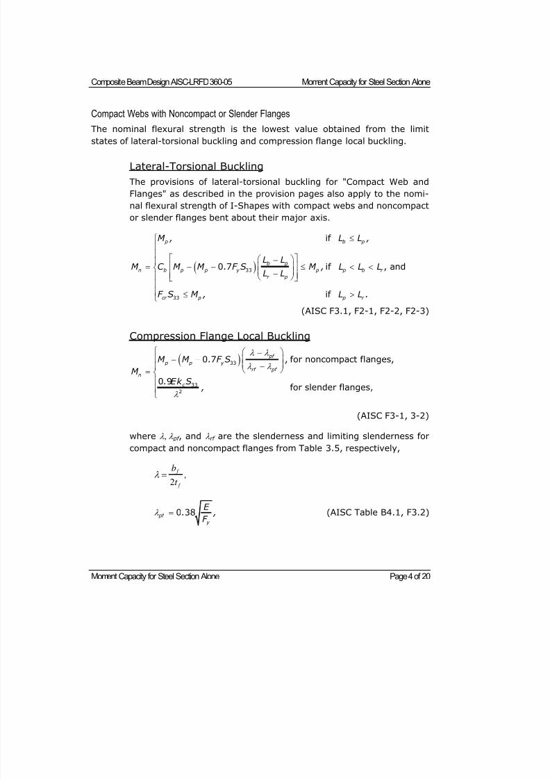
8/21/2019 Composit Beam
http://slidepdf.com/reader/full/composit-beam 97/161
Composite Beam Design AISC-LRFD 360-05 Moment Capacity for Steel Section Alone
Moment Capacity for Steel Section Alone Page 4 of 20
Compact Webs with Noncompact or Slender Flanges
The nominal flexural strength is the lowest value obtained from the limitstates of lateral-torsional buckling and compression flange local buckling.
Lateral-Torsional Buckling
The provisions of lateral-torsional buckling for "Compact Web and
Flanges" as described in the provision pages also apply to the nomi-
nal flexural strength of I-Shapes with compact webs and noncompact
or slender flanges bent about their major axis.
p b p
b p
n b p p y p p b r
r p
cr p p r
M , L L ,
L LM C M M . F S M , L L LL L
F S M , L L .
33
33
if
0 7 if , and
if
(AISC F3.1, F2-1, F2-2, F2-3)
Compression Flange Local Buckling
pf
p p y
rf pf n
c
M M . F S
M . Ek S
,
33
33
2,
0 7 , for noncompact flanges,
0 9
for slender flanges
(AISC F3-1, 3-2)
where pf , and rf are the slenderness and limiting slenderness for
compact and noncompact flanges from Table 3.5, respectively,
2
f
f
b ,
t
pf
y
E . ,
F
0 38 (AISC Table B4.1, F3.2)
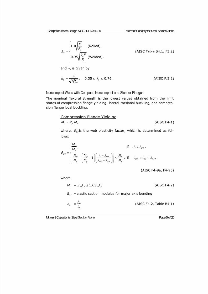
8/21/2019 Composit Beam
http://slidepdf.com/reader/full/composit-beam 98/161
Composite Beam Design AISC-LRFD 360-05 Moment Capacity for Steel Section Alone
Moment Capacity for Steel Section Alone Page 5 of 20
y
rf
c
L
E .
F
k E .
F
1 0 (Rolled),
0 95 (Welded),
(AISC Table B4.1, F3.2)
and c k is given by
c c
w
k , . k . .h t
4
0 35 0 76 (AISC F.3.2)
Noncompact Webs with Compact, Noncompact and Slender Flanges
The nominal flexural strength is the lowest values obtained from the limitstates of compression flange yielding, lateral-torsional buckling, and compres-
sion flange local buckling.
Compression Flange Yielding
n pc y M R M , (AISC F4-1)
where, pc R is the web plasticity factor, which is determined as fol-
lows:
p
pw y
pc
p p pw p
pw w rw
y y rw pw y
M
, ,M R
M M M , ,
M M M
if
1 if
(AISC F4-9a, F4-9b)
where,
pM = y y Z F . S F 33 331 6 (AISC F4-2)
S33 = elastic section modulus for major axis bending
w = c
w
h
t (AISC F4.2, Table B4.1)
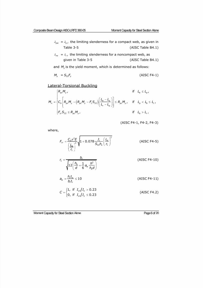
8/21/2019 Composit Beam
http://slidepdf.com/reader/full/composit-beam 99/161
Composite Beam Design AISC-LRFD 360-05 Moment Capacity for Steel Section Alone
Moment Capacity for Steel Section Alone Page 6 of 20
pw = p , the limiting slenderness for a compact web, as given in
Table 3-5 (AISC Table B4.1)
rw = r , the limiting slenderness for a noncompact web, as
given in Table 3-5 (AISC Table B4.1)
and y M is the yield moment, which is determined as follows:
y M = y S F 33 (AISC F4-1)
Lateral-Torsional Buckling
pc y b p
b p
n b pc y pc y L 33 pc y p b r
r p
cr 33 pc y b r
R M , L L ,
L LM C R M R M F S R M , L L L ,
L L
F S R M , L L ,
if
if
if
(AISC F4-1, F4-2, F4-3)
where,
b c bcr
o t b
t
C E J LF .
S h r Lr
22
2
33
1 0 078 (AISC F4-5)
f t
w
br
h ha
d h d
20
0
112
6
(AISC F4-10)
c w w
f f
h t a
b t 10 (AISC F4-11)
yc y
yc y
, I I .
C I I .
1 if 0 23
0, if 0 23 (AISC F4.2)
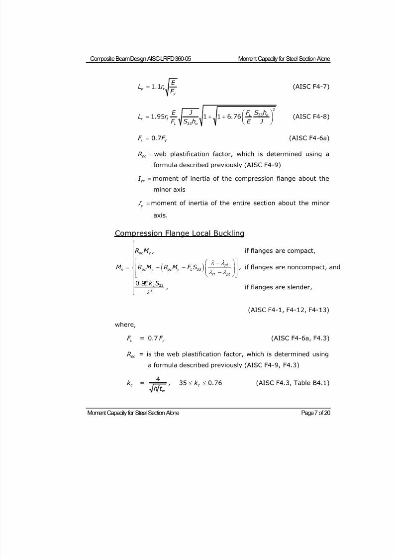
8/21/2019 Composit Beam
http://slidepdf.com/reader/full/composit-beam 100/161
Composite Beam Design AISC-LRFD 360-05 Moment Capacity for Steel Section Alone
Moment Capacity for Steel Section Alone Page 7 of 20
p t
y
E L . r
F
1 1 (AISC F4-7)
L or t
L o
E J F S hL . r .
F S h E J
2
33
33
1 95 1 1 6 76 (AISC F4-8)
L y F . F 0 7 (AISC F4-6a)
pc R web plastification factor, which is determined using a
formula described previously (AISC F4-9)
yc I moment of inertia of the compression flange about the
minor axis
y I moment of inertia of the entire section about the minor
axis.
Compression Flange Local Buckling
pc y
pt
n pc y pc y L
rf pt
c
R M ,
M R M R M F S ,
. Ek S , ,
33
33
2
if flanges are compact,
if flanges are noncompact, and
0 9if flanges are slender
(AISC F4-1, F4-12, F4-13)
where,
LF = 0.7 y F (AISC F4-6a, F4.3)
pc R = is the web plastification factor, which is determined using
a formula described previously (AISC F4-9, F4.3)
c k =w
,h t
4 c k . 35 0 76 (AISC F4.3, Table B4.1)
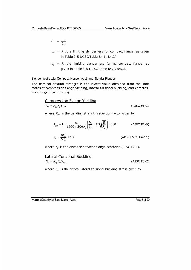
8/21/2019 Composit Beam
http://slidepdf.com/reader/full/composit-beam 101/161
Composite Beam Design AISC-LRFD 360-05 Moment Capacity for Steel Section Alone
Moment Capacity for Steel Section Alone Page 8 of 20
= f
f
b
t 2
pf = p , the limiting slenderness for compact flange, as given
in Table 3-5 (AISC Table B4.1, B4.3)
rf = r , the limiting slenderness for noncompact flange, as
given in Table 3-5 (AISC Table B4.1, B4.3).
Slender Webs with Compact, Noncompact, and Slender Flanges
The nominal flexural strength is the lowest value obtained from the limit
states of compression flange yielding, lateral-torsional buckling, and compres-
sion flange local buckling.
Compression Flange Yielding
n pg y M R F S 33, (AISC F5-1)
where pgR is the bending strength reduction factor given by
c w pg
w w y
ha E R
a t F
1 5.7 1.0,1200 300
(AISC F5-6)
w w
f f
ht ab t
10, (AISC F5.2, F4-11)
where 0h is the distance between flange centroids (AISC F2.2).
Lateral-Torsional Buckling
n pg cr M R F S 33, (AISC F5-2)
where cr F is the critical lateral-torsional buckling stress given by
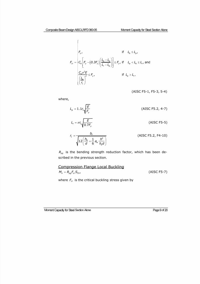
8/21/2019 Composit Beam
http://slidepdf.com/reader/full/composit-beam 102/161
Composite Beam Design AISC-LRFD 360-05 Moment Capacity for Steel Section Alone
Moment Capacity for Steel Section Alone Page 9 of 20
y b p
b p
cr b y y y p b r
r p
2
by p r 2
b
t
,
F , L L ,
L LF C F 0.3F F L L L
L L
C E F , L L
L
r
if
, if , and
if
(AISC F5-1, F5-3, 5-4)
where,
p t
y
E L r
F 1.1 (AISC F5.2, 4-7)
.r t
y
E L r
F
0 7 (AISC F5-5)
f t
w
br
h ha
d h d
20
0
112
6
(AISC F5.2, F4-10)
pgR is the bending strength reduction factor, which has been de-
scribed in the previous section.
Compression Flange Local Buckling
n pg cr M R F S 33, (AISC F5-7)
where cr F is the critical buckling stress given by
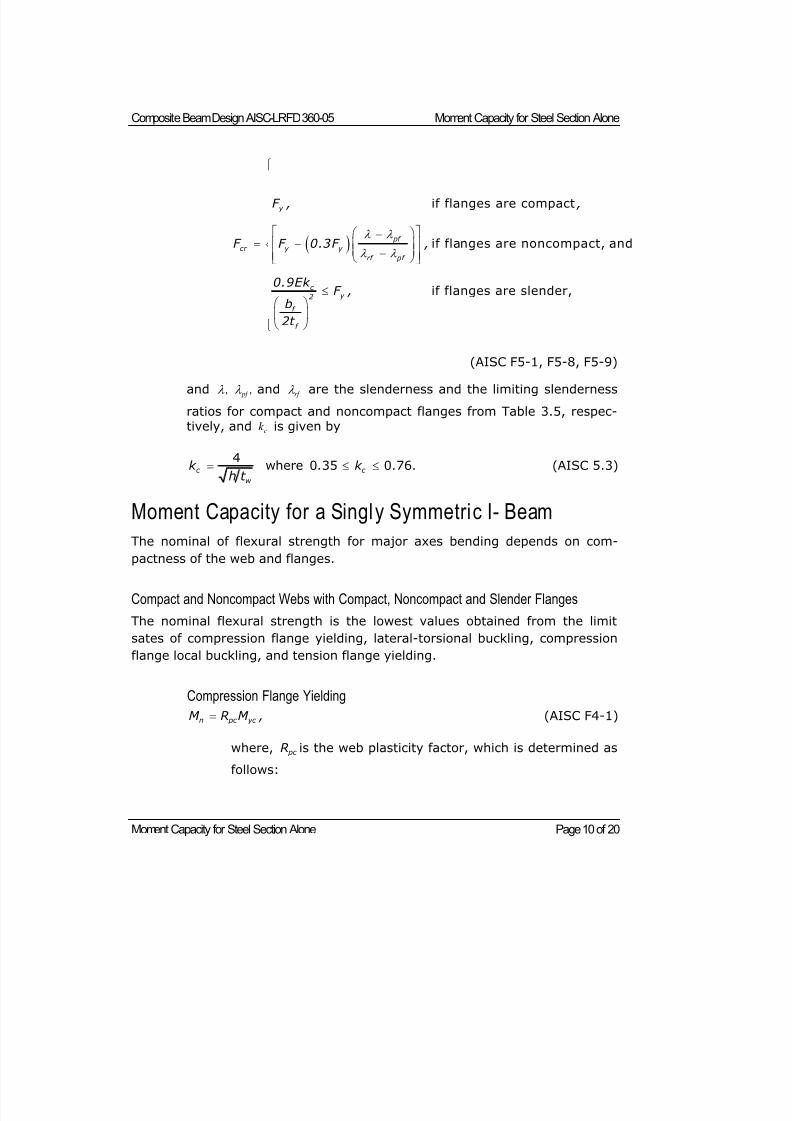
8/21/2019 Composit Beam
http://slidepdf.com/reader/full/composit-beam 103/161
Composite Beam Design AISC-LRFD 360-05 Moment Capacity for Steel Section Alone
Moment Capacity for Steel Section Alone Page 10 of 20
y
pf
cr y y
rf pf
c y 2
f
f
F , ,
F F 0.3F ,
0.9Ek F ,
b
2t
if flanges are compact
if flanges are noncompact, and
if flanges are slender,
(AISC F5-1, F5-8, F5-9)
and , pf , and rf are the slenderness and the limiting slenderness
ratios for compact and noncompact flanges from Table 3.5, respec-tively, and ck is given by
c c
w
k . k . .h t
4
where 0 35 0 76 (AISC 5.3)
Moment Capacity for a Singly Symmetric I- Beam
The nominal of flexural strength for major axes bending depends on com-
pactness of the web and flanges.
Compact and Noncompact Webs with Compact, Noncompact and Slender Flanges
The nominal flexural strength is the lowest values obtained from the limit
sates of compression flange yielding, lateral-torsional buckling, compression
flange local buckling, and tension flange yielding.
Compression Flange Yielding
n pc yc M R M , (AISC F4-1)
where, pc R is the web plasticity factor, which is determined asfollows:
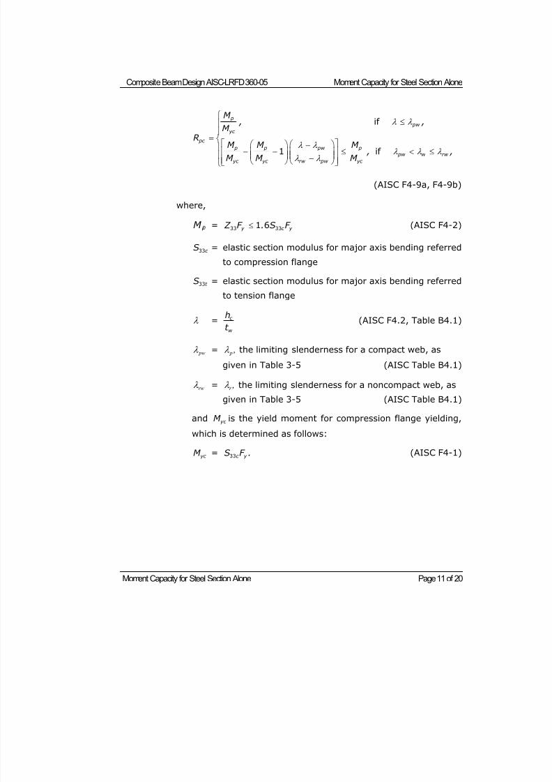
8/21/2019 Composit Beam
http://slidepdf.com/reader/full/composit-beam 104/161
Composite Beam Design AISC-LRFD 360-05 Moment Capacity for Steel Section Alone
Moment Capacity for Steel Section Alone Page 11 of 20
p
pw
yc
pc
p p pw p
pw w rw
yc yc rw pw yc
M , ,
M RM M M
, ,M M M
if
1 if
(AISC F4-9a, F4-9b)
where,
M = y c y Z F . S F 33 331 6 (AISC F4-2)
c S33 = elastic section modulus for major axis bending referred
to compression flange
t S33 = elastic section modulus for major axis bending referred
to tension flange
= c
w
h
t (AISC F4.2, Table B4.1)
pw = p , the limiting slenderness for a compact web, as
given in Table 3-5 (AISC Table B4.1)
rw = r , the limiting slenderness for a noncompact web, as
given in Table 3-5 (AISC Table B4.1)
and yc M is the yield moment for compression flange yielding,
which is determined as follows:
yc M = c y S F .33 (AISC F4-1)
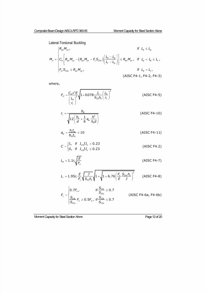
8/21/2019 Composit Beam
http://slidepdf.com/reader/full/composit-beam 105/161
Composite Beam Design AISC-LRFD 360-05 Moment Capacity for Steel Section Alone
Moment Capacity for Steel Section Alone Page 12 of 20
Lateral-Torsional Buckling
if
if
if
pc yc b p
b p
n b pc yc pc yc L 33c pc yc p b r
r p
cr 33c pc yc b r
R M , L L
L LM C R M R M F S R M , L L L ,
L L
F S R M , L L ,
(AISC F4-1, F4-2, F4-3)
where,
b c bcr
o t b
t
C E J LF
S h r Lr
22
2
33
1 0078. (AISC F4-5)
fc t
w
br
h ha
d h d
20
0
112
6
(AISC F4-10)
c w w
fe fc
h t a
b t 10 (AISC F4-11)
yc y
yc y
, I I .
C I I .
1 if 0 23
0, if 0 23 (AISC F4.2)
p t
y
E L . r
F 1 1 (AISC F4-7)
L c or t
L o
E J F S hL . r .
F S h E J
2
33
33
1 95 1 1 6 76 (AISC F4-8)
t y
c
Lt t
y y
c c
S. F , .
S
F S SF . F , .
S S
33
33
33 33
33 33
0 7 if 0 7
0 5 if 0 7 (AISC F4-6a, F4-6b)
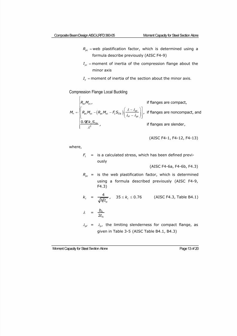
8/21/2019 Composit Beam
http://slidepdf.com/reader/full/composit-beam 106/161
Composite Beam Design AISC-LRFD 360-05 Moment Capacity for Steel Section Alone
Moment Capacity for Steel Section Alone Page 13 of 20
pc R web plastification factor, which is determined using a
formula describe previously (AISC F4-9)
yc I moment of inertia of the compression flange about the
minor axis
y I moment of inertia of the section about the minor axis.
Compression Flange Local Buckling
pc yc
pt
n pc yc pc yc L c
rf pt
c c
R M ,
M R M R M F S ,
. Ek S , ,
33
33
2
if flanges are compact,
if flanges are noncompact, and
0 9if flanges are slender
(AISC F4-1, F4-12, F4-13)
where,
LF = is a calculated stress, which has been defined previ-
ously
(AISC F4-6a, F4-6b, F4.3)
pc R = is the web plastification factor, which is determined
using a formula described previously (AISC F4-9,
F4.3)
c k =w
,h t
4 c k . 35 0 76 (AISC F4.3, Table B4.1)
= fc
fc
b
t 2
pf = p , the limiting slenderness for compact flange, asgiven in Table 3-5 (AISC Table B4.1, B4.3)
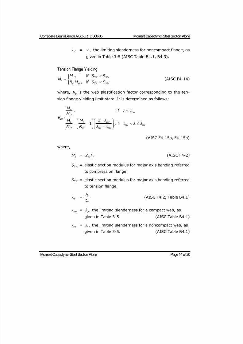
8/21/2019 Composit Beam
http://slidepdf.com/reader/full/composit-beam 107/161
Composite Beam Design AISC-LRFD 360-05 Moment Capacity for Steel Section Alone
Moment Capacity for Steel Section Alone Page 14 of 20
rf = r , the limiting slenderness for noncompact flange, as
given in Table 3-5 (AISC Table B4.1, B4.3).
Tension Flange Yielding
33 33
33 33
if
if
p t c
n
pt yt t c
M , S SM
R M , S S
(AISC F4-14)
where, pt R is the web plastification factor corresponding to the ten-
sion flange yielding limit state. It is determined as follows:
if
1 if
p
pw
yt pt
p p pw
pw rw
yt yt rw pw
M ,
M RM M
,M M
(AISC F4-15a, F4-15b)
where,
pM = 33 y Z F (AISC F4-2)
33c S = elastic section modulus for major axis bending referred
to compression flange
33t S = elastic section modulus for major axis bending referred
to tension flange
w = c
w
h
t (AISC F4.2, Table B4.1)
pw = p , the limiting slenderness for a compact web, as
given in Table 3-5 (AISC Table B4.1)
rw = r , the limiting slenderness for a noncompact web, as
given in Table 3-5. (AISC Table B4.1)
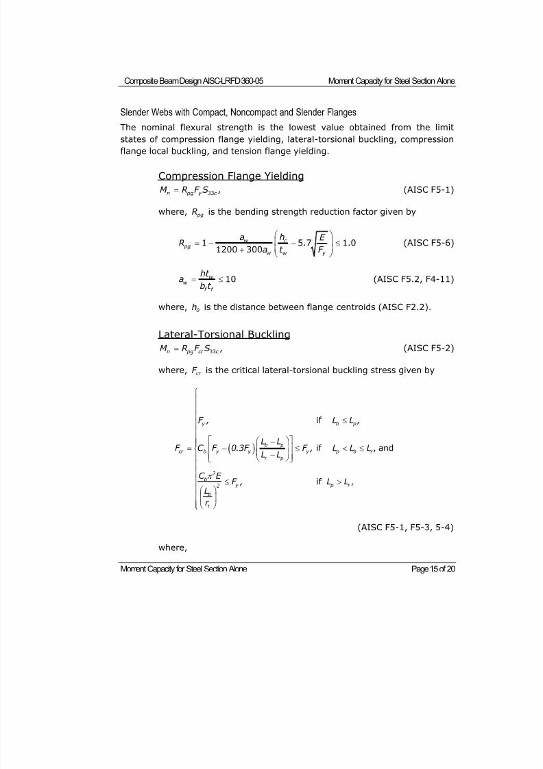
8/21/2019 Composit Beam
http://slidepdf.com/reader/full/composit-beam 108/161
Composite Beam Design AISC-LRFD 360-05 Moment Capacity for Steel Section Alone
Moment Capacity for Steel Section Alone Page 15 of 20
Slender Webs with Compact, Noncompact and Slender Flanges
The nominal flexural strength is the lowest value obtained from the limitstates of compression flange yielding, lateral-torsional buckling, compression
flange local buckling, and tension flange yielding.
Compression Flange Yielding
33 ,n pg y c M R F S (AISC F5-1)
where, pgR is the bending strength reduction factor given by
1 5.7 1.01200 300
c w pg
w w y
ha E R
a t F
(AISC F5-6)
10w w
f f
ht a
b t (AISC F5.2, F4-11)
where, 0h is the distance between flange centroids (AISC F2.2).
Lateral-Torsional Buckling
33 ,n pg cr c M R F S (AISC F5-2)
where, cr F is the critical lateral-torsional buckling stress given by
if
, if , and
if
y b p
b p
cr b y y y p b r
r p
2
by p r 2
b
t
,
F , L L ,
L LF C F 0.3F F L L L
L L
C E F , L L
L
r
(AISC F5-1, F5-3, 5-4)
where,
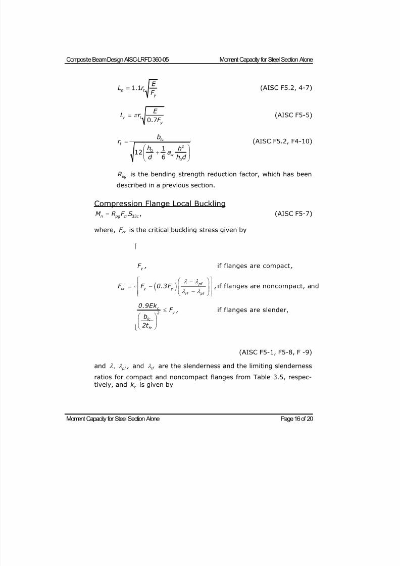
8/21/2019 Composit Beam
http://slidepdf.com/reader/full/composit-beam 109/161
Composite Beam Design AISC-LRFD 360-05 Moment Capacity for Steel Section Alone
Moment Capacity for Steel Section Alone Page 16 of 20
1.1 p t
y
E L r
F
(AISC F5.2, 4-7)
0.7r t
y
E L r
F (AISC F5-5)
20
0
112
6
fc t
w
br
h ha
d h d
(AISC F5.2, F4-10)
pgR is the bending strength reduction factor, which has been
described in a previous section.
Compression Flange Local Buckling
33 ,n pg cr c M R F S (AISC F5-7)
where, cr F is the critical buckling stress given by
if flanges are compact
if flanges are noncompact, and
if flanges are slender,
y
pf cr y y
rf pf
c y 2
fc
fc
F , ,
F F 0.3F ,
0.9Ek F ,
b
2t
(AISC F5-1, F5-8, F -9)
and , pf , and rf are the slenderness and the limiting slenderness
ratios for compact and noncompact flanges from Table 3.5, respec-tively, and c k is given by
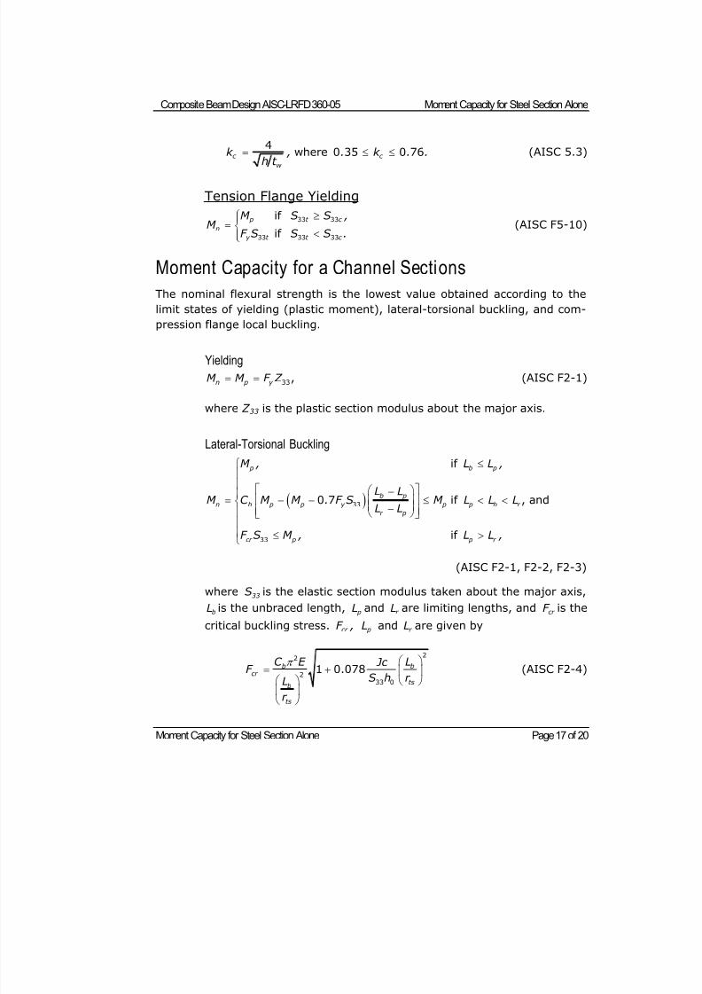
8/21/2019 Composit Beam
http://slidepdf.com/reader/full/composit-beam 110/161
Composite Beam Design AISC-LRFD 360-05 Moment Capacity for Steel Section Alone
Moment Capacity for Steel Section Alone Page 17 of 20
4where 0 35 0 76c c
w
k , . k . .
h t
(AISC 5.3)
Tension Flange Yielding
33 33
33 33 33
if
if
p t c
n
y t t c
M S S ,M
F S S S .
(AISC F5-10)
Moment Capacity for a Channel Sections
The nominal flexural strength is the lowest value obtained according to the
limit states of yielding (plastic moment), lateral-torsional buckling, and com-
pression flange local buckling.
Yielding
33,n p y M M F Z (AISC F2-1)
where Z 33 is the plastic section modulus about the major axis.
Lateral-Torsional Buckling
33
33
if
0 7 if , and
if
p b p
b p
n b p p y p p b r
r p
cr p p r
M , L L ,
L L
M C M M . F S M L L LL L
F S M , L L ,
(AISC F2-1, F2-2, F2-3)
where 33S is the elastic section modulus taken about the major axis,
bL is the unbraced length, pL and r L are limiting lengths, and cr F is the
critical buckling stress. cr F , pL and r L are given by
22
233 0
1 0.078b bcr
tsb
ts
C E L Jc F S h r L
r
(AISC F2-4)
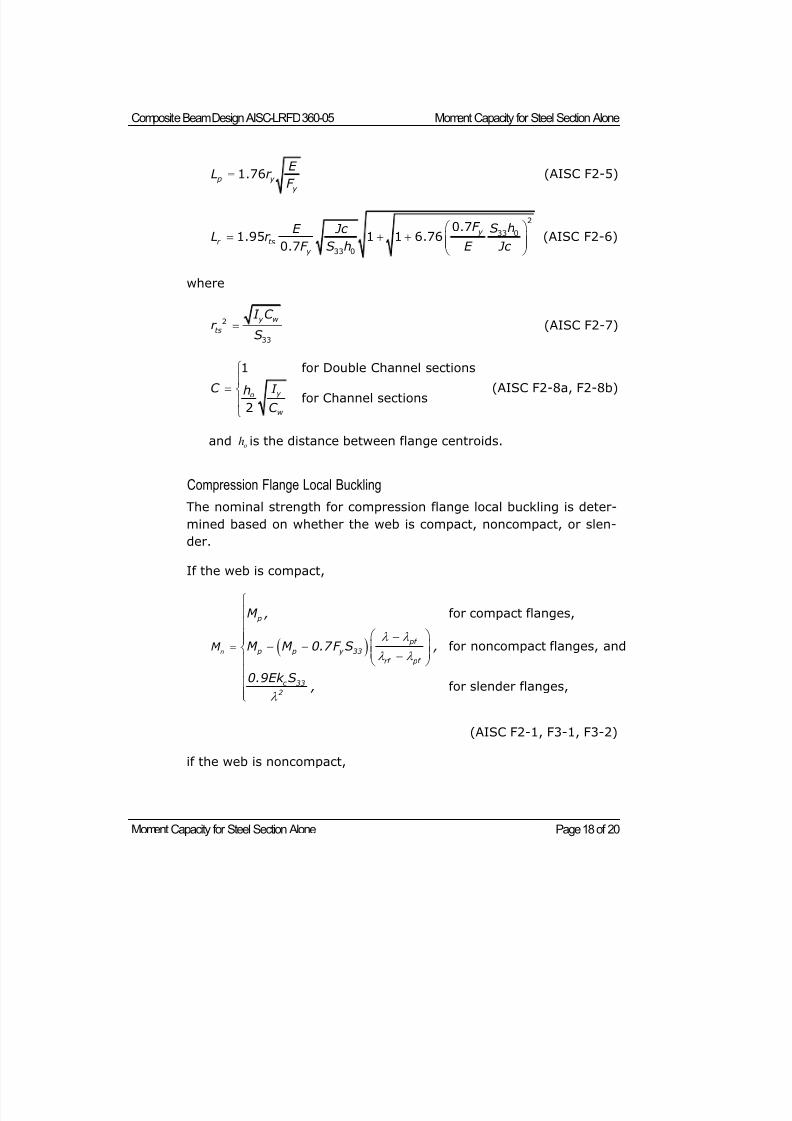
8/21/2019 Composit Beam
http://slidepdf.com/reader/full/composit-beam 111/161
Composite Beam Design AISC-LRFD 360-05 Moment Capacity for Steel Section Alone
Moment Capacity for Steel Section Alone Page 18 of 20
1.76 p y
y
E L r
F
(AISC F2-5)
2
33 0
33 0
0.71.95 1 1 6.76
0.7
y
r ts
y
F S hE Jc L r
F S h E Jc
(AISC F2-6)
where
2
33
y w
ts
I C r
S (AISC F2-7)
1 for Double Channel sections
for Channel sections2
y o
w
C I h
C
(AISC F2-8a, F2-8b)
and oh is the distance between flange centroids.
Compression Flange Local Buckling
The nominal strength for compression flange local buckling is deter-
mined based on whether the web is compact, noncompact, or slen-
der.
If the web is compact,
for compact flanges,
for noncompact flanges, and
for slender flanges,
n
p
pf
p p y 33
rf pf
c 33
2
M
M ,
M M 0.7F S ,
0.9Ek S ,
(AISC F2-1, F3-1, F3-2)
if the web is noncompact,
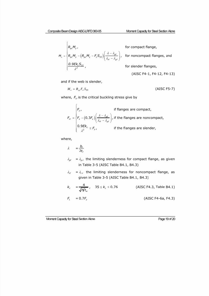
8/21/2019 Composit Beam
http://slidepdf.com/reader/full/composit-beam 112/161
Composite Beam Design AISC-LRFD 360-05 Moment Capacity for Steel Section Alone
Moment Capacity for Steel Section Alone Page 19 of 20
for compact flange,
for noncompact flanges, and
for slender flanges,
n
pc y
pf
pc y pc y L 33
rf pf
c 33
2
M
R M ,
R M R M F S ,
0.9Ek S ,
(AISC F4-1, F4-12, F4-13)
and if the web is slender,
33n pg cr M R F S (AISC F5-7)
where,cr
F is the critical buckling stress give by
2
if flanges are compact,
0 3 if the flanges are noncompact,
0 9if the flanges are slender,
y
pf
cr y y
rf pf
c y
F ,
F F . F ,
. Ek F ,
where,
= 2f
f
b
t
pf = p , the limiting slenderness for compact flange, as given
in Table 3-5 (AISC Table B4.1, B4.3)
rf = r , the limiting slenderness for noncompact flange, as
given in Table 3-5 (AISC Table B4.1, B4.3)
c k =4
w
,h t
35 0 76c k . (AISC F4.3, Table B4.1)
LF = 0 7 y . F (AISC F4-6a, F4.3)
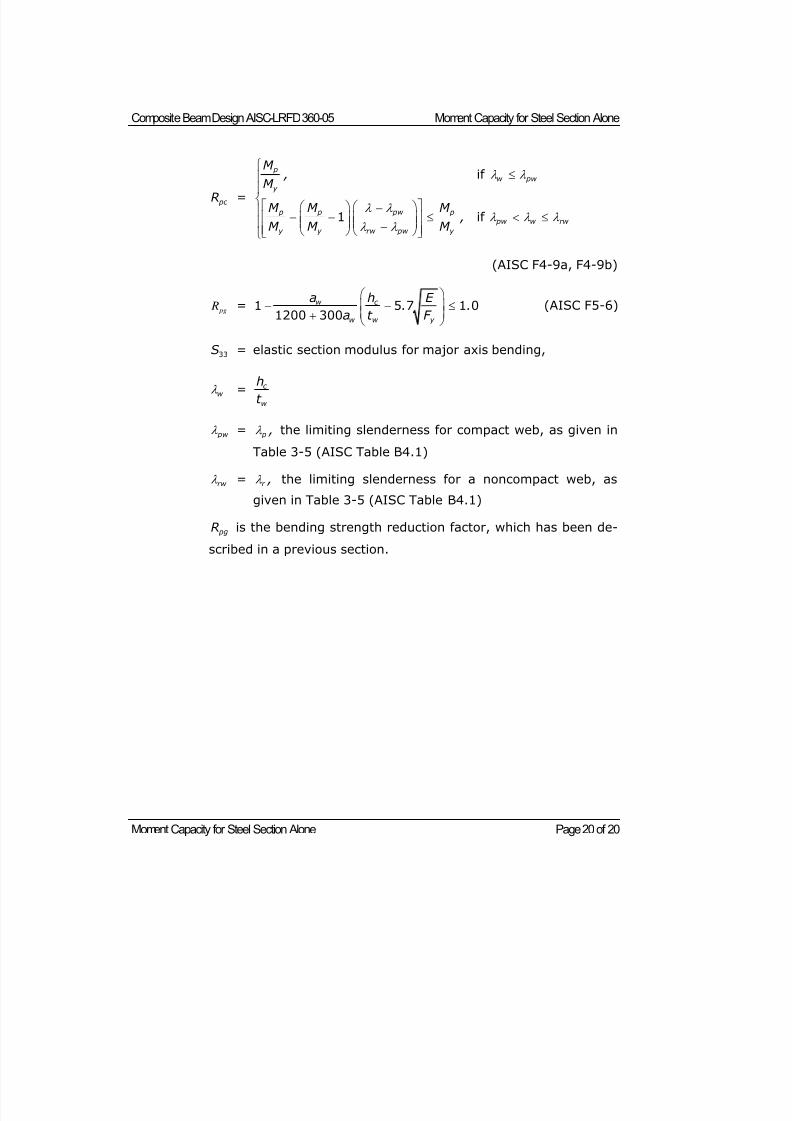
8/21/2019 Composit Beam
http://slidepdf.com/reader/full/composit-beam 113/161
Composite Beam Design AISC-LRFD 360-05 Moment Capacity for Steel Section Alone
Moment Capacity for Steel Section Alone Page 20 of 20
pc R =
if
1 if
p
w pw
y
p p pw p
pw w rw
y y rw pw y
M ,
M M M M
,M M M
(AISC F4-9a, F4-9b)
pg R = 1 5 7 1 01200 300
w c
w w y
a h E . .
a t F
(AISC F5-6)
33S = elastic section modulus for major axis bending,
w = c
w
h
t
pw = p , the limiting slenderness for compact web, as given in
Table 3-5 (AISC Table B4.1)
rw = r , the limiting slenderness for a noncompact web, as
given in Table 3-5 (AISC Table B4.1)
pgR is the bending strength reduction factor, which has been de-
scribed in a previous section.
8/21/2019 Composit Beam
http://slidepdf.com/reader/full/composit-beam 114/161
Partial Composite Connection with a Plastic Stress Distribution Page 1 of 6
©COMPUTERS AND STRUCTURES, INC., BERKELEY, C ALIFORNIA JUNE 2009
COMPOSITEBEAMDESIGN AISC-LRFD 360-05
Technical NotePartial Composite Connection w ith a Plastic
Stress Distribution
This technical note describes how the positive moment capacity of the com-
posite beam using plastic stress distribution is calculated for partial composite
connection. Partial composite connection for an elastic stress distribution is
described in Composite Beam Design AISC-ASD89 Technical Note Elastic
Stresses with Partial Composite Connection and Composite Beam Design
AISC-LRFD 360-05 Technical Note Composite Section Elastic Moment Capac-ity.
Estimating the Required Percent Composite Connection
The program uses Equation 1 to estimate the required percent composite
connection (PCC) for a composite beam.
2
u n steel beam
n X% comp n steel beam
M M PCC X%
M M
Eqn. 1
where,
PCC = Required percent composite connection, unitless.
M u = Required flexural strength, that is, the applied factored
moment, kip-in.
M n X% comp = Nominal flexural strength (capacity) of composite section
with X% composite connection, kip-in.
M n steel beam = Nominal flexural strength (capacity) of the steel beam
section alone as determined from Composite Beam Design
AISC-LRFD 360-05 Technical Note Moment Capacity forSteel Section Alone, kip-in.
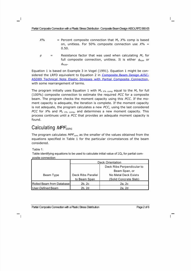
8/21/2019 Composit Beam
http://slidepdf.com/reader/full/composit-beam 115/161
Partial Composite Connection with a Plastic Stress Distribution Composite Beam Design AISC-LRFD 360-05
Partial Composite Connection with a Plastic Stress Distribution Page 2 of 6
X % = Percent composite connection that M n X % comp is based
on, unitless. For 50% composite connection use X % =0.50.
= Resistance factor that was used when calculating M n for
full composite connection, unitless. It is either bcpe or
bcpp.
Equation 1 is based on Example 3 in Vogel (1991). Equation 1 might be con-
sidered the LRFD equivalent to Equation 2 in Composite Beam Design AISC-
ASD89 Technical Note Elastic Stresses with Partial Composite Connection,
with some rearrangement of terms.
The program initially uses Equation 1 with M n X% comp equal to the M n for full(100%) composite connection to estimate the required PCC for a composite
beam. The program checks the moment capacity using this PCC . If the mo-
ment capacity is adequate, the iteration is complete. If the moment capacity
is not adequate, the program calculates a new PCC , using the last considered
PCC for X % and M n X% comp, and determines a new moment capacity. This
process continues until a PCC that provides an adequate moment capacity is
found.
Calculating MPF conc
The program calculates MPF conc as the smaller of the values obtained from theequations specified in Table 1 for the particular circumstances of the beam
considered.
Table 1:
Table identifying equations to be used to calculate initial value of Qn for partial com-
posite connection Deck Orientation
Beam Type Deck Ribs Parallel
to Beam Span
Deck Ribs Perpendicular to
Beam Span, or
No Metal Deck Exists
(Solid Concrete Slab)
Rolled Beam from Database 2b, 2c 2a, 2c
User-Defined Beam 2b, 2d 2a, 2d
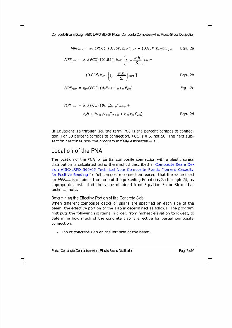
8/21/2019 Composit Beam
http://slidepdf.com/reader/full/composit-beam 116/161
Composite Beam Design AISC-LRFD 360-05 Partial Composite Connection with a Plastic Stress Distribution
Partial Composite Connection with a Plastic Stress Distribution Page 3 of 6
MPF conc = bcc (PCC ) [(0.85f 'c beff t c )left + (0.85f 'c beff t c )right] Eqn. 2a
MPF conc = bcc (PCC ) [(0.85f 'c beff r r
c
r
w ht
S
left +
(0.85f 'c beff r r
c
r
w ht
S
right ] Eqn. 2b
MPF conc = bcs(PCC ) ( AsF y + bcp t cp F ycp) Eqn. 2c
MPF conc = bcs(PCC ) (bf -topt f -topF yf -top +
t w h + bf -bott f -botF yf -bot + bcp t cp F ycp) Eqn. 2d
In Equations 1a through 1d, the term PCC is the percent composite connec-
tion. For 50 percent composite connection, PCC is 0.5, not 50. The next sub-
section describes how the program initially estimates PCC .
Location of the PNA
The location of the PNA for partial composite connection with a plastic stress
distribution is calculated using the method described in Composite Beam De-sign AISC-LRFD 360-05 Technical Note Composite Plastic Moment Capacity
for Positive Bending for full composite connection, except that the value used
for MPF conc is obtained from one of the preceding Equations 2a through 2d, as
appropriate, instead of the value obtained from Equation 3a or 3b of that
technical note.
Determining the Effective Portion of the Concrete Slab
When different composite decks or spans are specified on each side of the
beam, the effective portion of the slab is determined as follows: The program
first puts the following six items in order, from highest elevation to lowest, to
determine how much of the concrete slab is effective for partial compositeconnection:
Top of concrete slab on the left side of the beam.
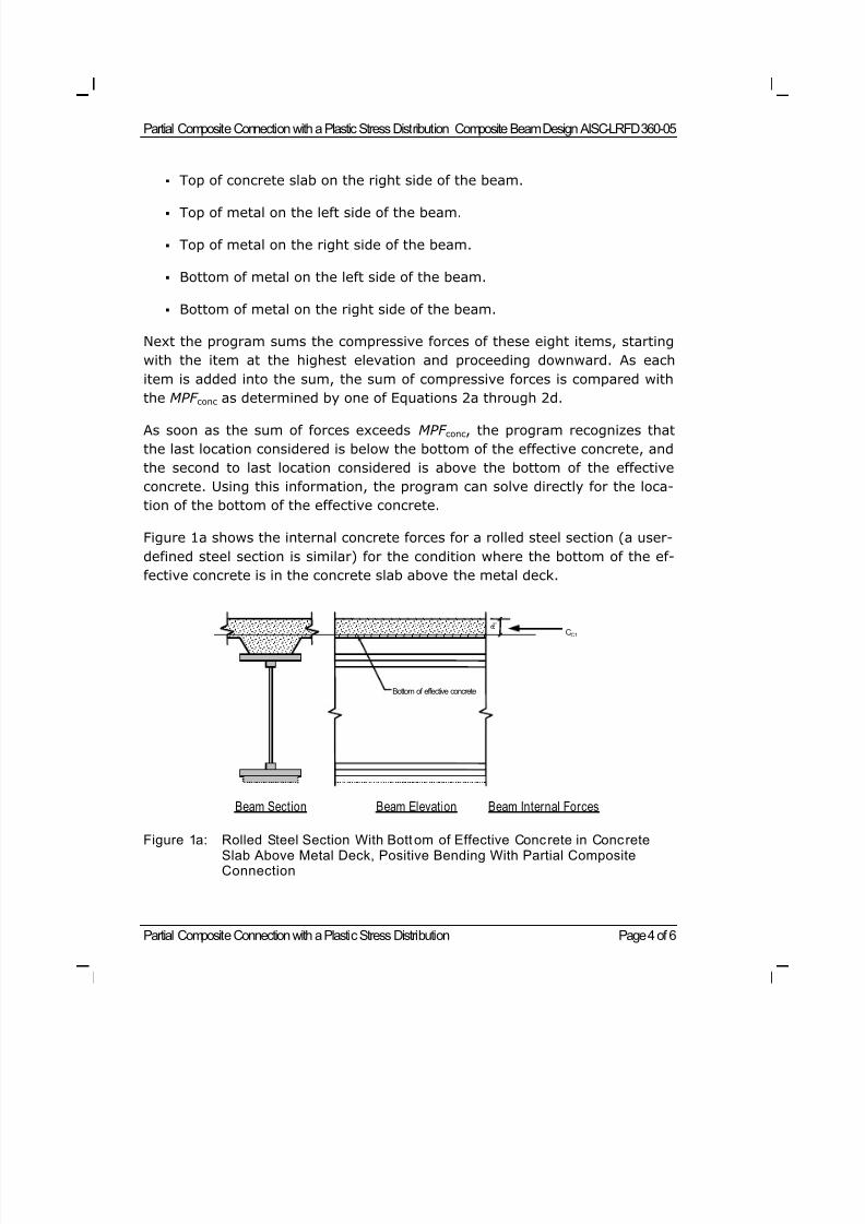
8/21/2019 Composit Beam
http://slidepdf.com/reader/full/composit-beam 117/161
Partial Composite Connection with a Plastic Stress Distribution Composite Beam Design AISC-LRFD 360-05
Partial Composite Connection with a Plastic Stress Distribution Page 4 of 6
Top of concrete slab on the right side of the beam.
Top of metal on the left side of the beam.
Top of metal on the right side of the beam.
Bottom of metal on the left side of the beam.
Bottom of metal on the right side of the beam.
Next the program sums the compressive forces of these eight items, starting
with the item at the highest elevation and proceeding downward. As each
item is added into the sum, the sum of compressive forces is compared with
the MPF conc as determined by one of Equations 2a through 2d.
As soon as the sum of forces exceeds MPF conc, the program recognizes that
the last location considered is below the bottom of the effective concrete, and
the second to last location considered is above the bottom of the effective
concrete. Using this information, the program can solve directly for the loca-
tion of the bottom of the effective concrete.
Figure 1a shows the internal concrete forces for a rolled steel section (a user-
defined steel section is similar) for the condition where the bottom of the ef-
fective concrete is in the concrete slab above the metal deck.
Figure 1a: Rolled Steel Section With Bottom of Effective Concrete in ConcreteSlab Above Metal Deck, Positive Bending With Partial CompositeConnection
CC1
Beam Section Beam Elevation Beam Internal Forces
Bottom of effective concrete
a 1
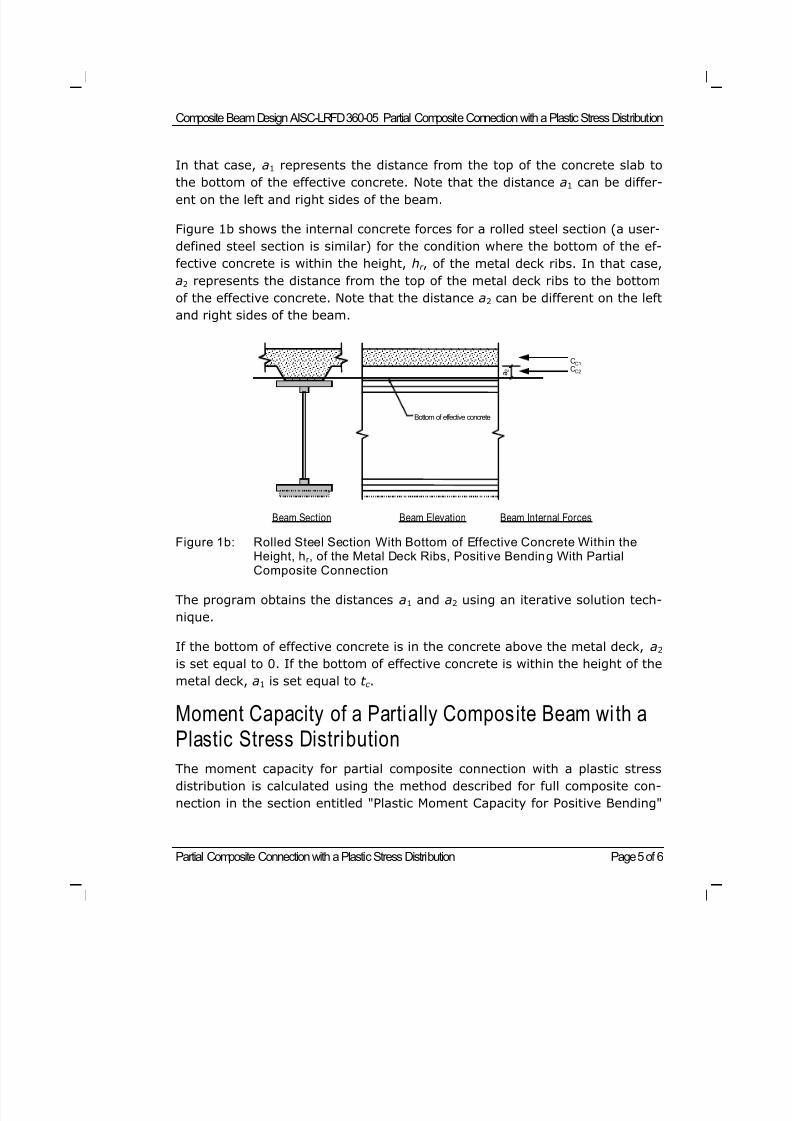
8/21/2019 Composit Beam
http://slidepdf.com/reader/full/composit-beam 118/161
Composite Beam Design AISC-LRFD 360-05 Partial Composite Connection with a Plastic Stress Distribution
Partial Composite Connection with a Plastic Stress Distribution Page 5 of 6
In that case, a1 represents the distance from the top of the concrete slab to
the bottom of the effective concrete. Note that the distance a1 can be differ-ent on the left and right sides of the beam.
Figure 1b shows the internal concrete forces for a rolled steel section (a user-
defined steel section is similar) for the condition where the bottom of the ef-
fective concrete is within the height, hr , of the metal deck ribs. In that case,
a2 represents the distance from the top of the metal deck ribs to the bottom
of the effective concrete. Note that the distance a2 can be different on the left
and right sides of the beam.
Figure 1b: Rolled Steel Section With Bottom of Effective Concrete Within theHeight, hr , of the Metal Deck Ribs, Positive Bending With PartialComposite Connection
The program obtains the distances a1 and a2 using an iterative solution tech-
nique.
If the bottom of effective concrete is in the concrete above the metal deck, a2
is set equal to 0. If the bottom of effective concrete is within the height of the
metal deck, a1 is set equal to t c .
Moment Capacity of a Partially Composite Beam with aPlastic Stress Distribution
The moment capacity for partial composite connection with a plastic stress
distribution is calculated using the method described for full composite con-
nection in the section entitled "Plastic Moment Capacity for Positive Bending"
CC1
Beam Section Beam Elevation Beam Internal Forces
CC2
Bottom of effective concrete
a 2
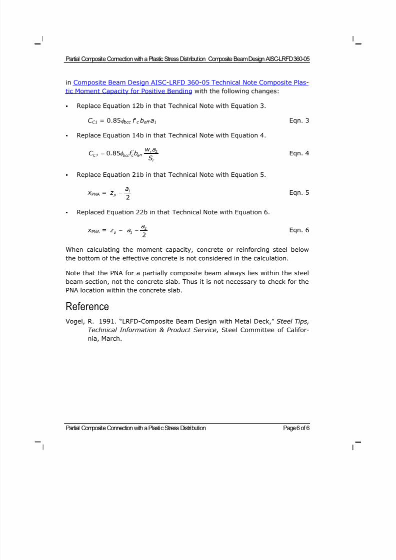
8/21/2019 Composit Beam
http://slidepdf.com/reader/full/composit-beam 119/161
Partial Composite Connection with a Plastic Stress Distribution Composite Beam Design AISC-LRFD 360-05
Partial Composite Connection with a Plastic Stress Distribution Page 6 of 6
in Composite Beam Design AISC-LRFD 360-05 Technical Note Composite Plas-
tic Moment Capacity for Positive Bending with the following changes:
Replace Equation 12b in that Technical Note with Equation 3.
C C 1 = 0.85 bcc f 'c beff a1 Eqn. 3
Replace Equation 14b in that Technical Note with Equation 4.
22 0 85 ' r
C bcc c eff
r
w aC . f b
S Eqn. 4
Replace Equation 21b in that Technical Note with Equation 5.
x PNA =1
2 p
a z Eqn. 5
Replaced Equation 22b in that Technical Note with Equation 6.
x PNA =2
12
p
a z a Eqn. 6
When calculating the moment capacity, concrete or reinforcing steel below
the bottom of the effective concrete is not considered in the calculation.
Note that the PNA for a partially composite beam always lies within the steel
beam section, not the concrete slab. Thus it is not necessary to check for thePNA location within the concrete slab.
Reference
Vogel, R. 1991. “LRFD-Composite Beam Design with Metal Deck,” Steel Tips,
Technical Information & Product Service, Steel Committee of Califor-
nia, March.
8/21/2019 Composit Beam
http://slidepdf.com/reader/full/composit-beam 120/161
Bending and Deflection Checks Page 1 of 2
©COMPUTERS AND STRUCTURES, INC., BERKELEY, C ALIFORNIA DECEMBER 2008
COMPOSITEBEAMDESIGN AISC-LRFD 360-05
Technical Note
Bending and Deflection Checks
This Technical Note describes how the program checks bending and deflection
for AISC-LRFD 360-05 design.
Bending Check Locations
For each design load combination the program checks bending at the follow-
ing locations:
Point of maximum moment for the design load combination considered.
Point load locations for the design load combination considered.
Bending Check at Point of Maximum Moment
For beams with no axial load, or when axial loads are not considered, the
program uses Equation 1 to perform bending checks for both composite and
noncomposite beams. If there is axial load to be considered, the interaction
formulas described in Composite Beam Design AISC-LRFD 360-05 Technical
Note Moment Capacity for Steel Section Alone are used rather than Equation1.
u
n
M1.0
M Eqn. 1
where,
Mu = The maximum required flexural strength, that is, the maximum
applied factored moment, kip-in.
Mn = Moment capacity for full composite connection or partial com-
posite connection, as applicable, kip-in.
= Resistance factor for bending, unitless. For positive bending in a
composite beam with an assumed plastic stress distribution,
8/21/2019 Composit Beam
http://slidepdf.com/reader/full/composit-beam 121/161
Composite Beam Design AISC-LRFD 360-05 Bending and Deflection Checks
Bending and Deflection Checks Page 2 of 2
bcpp is used. For negative bending in a composite beam with an
assumed plastic stress distribution, bcnp is used. For positivebending in a composite beam with an assumed elastic stress
distribution, bcpe is used. For negative bending in a composite
beam with an assumed elastic stress distribution, bcne is used.
If the beam is specified to be noncomposite, b is used.
If there is axial load to be considered, the interaction formulas described in
Composite Beam Design AISC-LRFD 360-05 Technical Note Moment Capacity
for Steel Section Alone are used rather than Equation 1.
Bending Check at Point Loads
The bending check at point load locations is performed by applying Equation 9in Composite Beam Design AISC-LRFD 360-05 Technical Note Shear Connec-
tors at the point load location. See the next section entitled "Bending Checks"
for additional information.
Deflection Check
Deflection is calculated as described in Composite Beam Design Technical
Note Beam Deflection and Camber. For full composite connection Itr is used in
the deflection calculations. For partial composite connection Ieff is used in the
deflection calculations.
8/21/2019 Composit Beam
http://slidepdf.com/reader/full/composit-beam 122/161
©COMPUTERS AND STRUCTURES, INC., BERKELEY, C ALIFORNIA JUNE 2009
COMPOSITEBEAMDESIGN AISC-LRFD 360-05
Technical Note
Shear Connectors
This Technical Note begins by defining the program's default allowable shear
connector loads for AISC-LRFD 360-05 composite beam design. Shear con-
nector capacities are defined for both shear studs and channel shear connec-
tors. Next the equations used for determining the number of shear connectors
on the beam are provided.
Shear Stud ConnectorsThe capacity for a single shear stud is calculated using Equation 1.
Qn = 0.5sc Asc ' c c f E RgR p Asc F u, Eqn. 1
Rg and R p are defined as follows:
Condition R g R p
Decking oriented parallel to the steel shape
1.5r
r
w
h
1.5r
r
w
h
1.0
0.85**
0.75
0.75
Decking oriented perpendicular to the steel shape.
Number of studs occupying the same deck rib
1
2
3 or more
1.0
0.85
0.7
0.6
0.6
0.6
where,
hr = nominal rib height, in.
8/21/2019 Composit Beam
http://slidepdf.com/reader/full/composit-beam 123/161
Shear Connectors Composite Beam Design AISC-LRFD 360-05
Shear Connectors Page 2 of 5
w r = average width of concrete rib or haunch, in.
** - For a single stud
Equation 1 is based on AISC-LRFD93 specifications Equation I5-1. The bs fac-
tor in Equation 1 is not specified by AISC. It is provided by CSI to allow addi-
tional control over the allowable shear connector load. The default value for
this factor is 1, but that value can be modified using both the preferences and
the overwrites.
If there is formed metal deck, the value of qrs obtained from either Equation 1
or from the overwrites, if specified, is reduced by a reduction factor, RF that
is specified in Composite Beam Design AISC-ASD89 Technical Note Shear
Studs. Note that the reduction factor is different depending on if the span ofthe metal deck ribs is oriented parallel or perpendicular to the span of the
beam.
The reduction factor, RF, applies only to the 0.5 sc Asc ' c c f E term in Equation
1. It does not apply to the RgR p Asc F u term.
The terms f ’ c and E c can be different on the two sides of the beam. The pro-
gram calculates qrs for each side of the beam separately using Equation 1 and
uses the smaller value in the calculations.
Channel Shear ConnectorsThe capacity for channel shear connectors is calculated using Equation 2.
Qn = 36.5 bs (t + 0.5t w )Lcsc '
cf E Eqn. 2
Equation 2 is based on AISC-LRFD 360-05 specifications Equation I5-2. The
bs factor in Equation 2 is the same as that described for Equation 1 in the
previous section.
Because the program does not allow channel shear connectors to be used
with formed metal deck, there is no reduction factor that needs to be applied
to the value of Qn calculated using Equation 2.
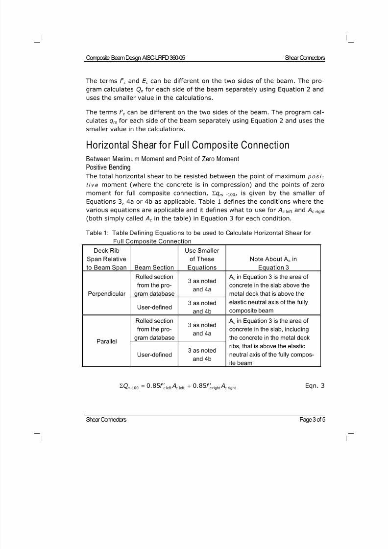
8/21/2019 Composit Beam
http://slidepdf.com/reader/full/composit-beam 124/161
Composite Beam Design AISC-LRFD 360-05 Shear Connectors
Shear Connectors Page 3 of 5
The terms f ’ c and E c can be different on the two sides of the beam. The pro-
gram calculates Qn for each side of the beam separately using Equation 2 anduses the smaller value in the calculations.
The terms f ’ c can be different on the two sides of the beam. The program cal-
culates qrs for each side of the beam separately using Equation 2 and uses the
smaller value in the calculations.
Horizontal Shear for Full Composite Connection
Between Maximum Moment and Point of Zero MomentPositive Bending
The total horizontal shear to be resisted between the point of maximum p o s i -
t i v e moment (where the concrete is in compression) and the points of zeromoment for full composite connection, qrs -100, is given by the smaller of
Equations 3, 4a or 4b as applicable. Table 1 defines the conditions where the
various equations are applicable and it defines what to use for Ac left and Ac right
(both simply called Ac in the table) in Equation 3 for each condition.
Table 1: Table Defining Equations to be used to Calculate Horizontal Shear for
Full Composite Connection
Deck Rib
Span Relative
to Beam Span Beam Section
Use Smaller
of These
Equations
Note About Ac in
Equation 3
Rolled sectionfrom the pro-
gram database
3 as noted
and 4aPerpendicular
User-defined3 as noted
and 4b
Ac in Equation 3 is the area ofconcrete in the slab above the
metal deck that is above the
elastic neutral axis of the fully
composite beam
Rolled section
from the pro-
gram database
3 as noted
and 4a
Parallel
User-defined3 as noted
and 4b
Ac in Equation 3 is the area of
concrete in the slab, including
the concrete in the metal deck
ribs, that is above the elastic
neutral axis of the fully compos-
ite beam
100 left left right right0 85 0 85n c c c c Q . f A . f A Eqn. 3
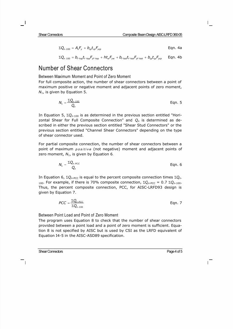
8/21/2019 Composit Beam
http://slidepdf.com/reader/full/composit-beam 125/161
Shear Connectors Composite Beam Design AISC-LRFD 360-05
Shear Connectors Page 4 of 5
100n s y cp cp ycpQ A F b t F Eqn. 4a
100 top top top bot bot botn f - f - yf - w yw f - f - yf - cp cp ycpQ b t F ht F b t F b t F Eqn. 4b
Number of Shear Connectors
Between Maximum Moment and Point of Zero Moment
For full composite action, the number of shear connectors between a point of
maximum positive or negative moment and adjacent points of zero moment,
N 1, is given by Equation 5.
1001
n
n
QN
Q
Eqn. 5
In Equation 5, Qn-100 is as determined in the previous section entitled "Hori-
zontal Shear for Full Composite Connection" and Qn is determined as de-
scribed in either the previous section entitled "Shear Stud Connectors" or the
previous section entitled "Channel Shear Connectors" depending on the type
of shear connector used.
For partial composite connection, the number of shear connectors between a
point of maximum p o s i t i v e (not negative) moment and adjacent points of
zero moment, N 1, is given by Equation 6.
1
n PCC
n
Q
N Q
Eqn. 6
In Equation 6, Qn-PCC is equal to the percent composite connection times Qn-
100. For example, if there is 70% composite connection, Qn-PCC = 0.7 Qn-100.
Thus, the percent composite connection, PCC, for AISC-LRFD93 design is
given by Equation 7.
100
n PCC
n
QPCC
Q
Eqn. 7
Between Point Load and Point of Zero Moment
The program uses Equation 8 to check that the number of shear connectorsprovided between a point load and a point of zero moment is sufficient. Equa-
tion 8 is not specified by AISC but is used by CSI as the LRFD equivalent of
Equation I4-5 in the AISC-ASD89 specification.
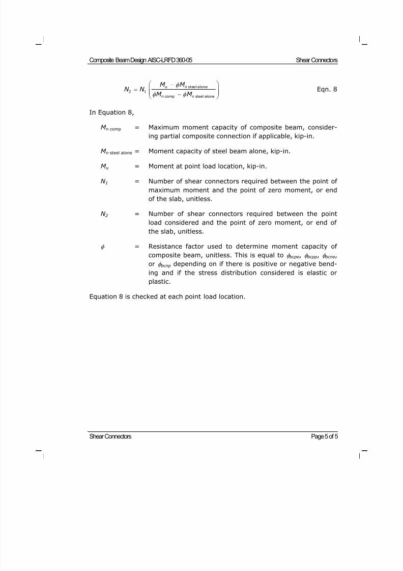
8/21/2019 Composit Beam
http://slidepdf.com/reader/full/composit-beam 126/161
Composite Beam Design AISC-LRFD 360-05 Shear Connectors
Shear Connectors Page 5 of 5
steel alone
2 1
comp steel alone
u n
n n
M M N N
M M
Eqn. 8
In Equation 8,
M n comp = Maximum moment capacity of composite beam, consider-
ing partial composite connection if applicable, kip-in.
M n steel alone = Moment capacity of steel beam alone, kip-in.
M u = Moment at point load location, kip-in.
N 1 = Number of shear connectors required between the point of
maximum moment and the point of zero moment, or endof the slab, unitless.
N 2 = Number of shear connectors required between the point
load considered and the point of zero moment, or end of
the slab, unitless.
= Resistance factor used to determine moment capacity of
composite beam, unitless. This is equal to bcpe, bcpp, bcne,
or bcnp depending on if there is positive or negative bend-
ing and if the stress distribution considered is elastic or
plastic.
Equation 8 is checked at each point load location.
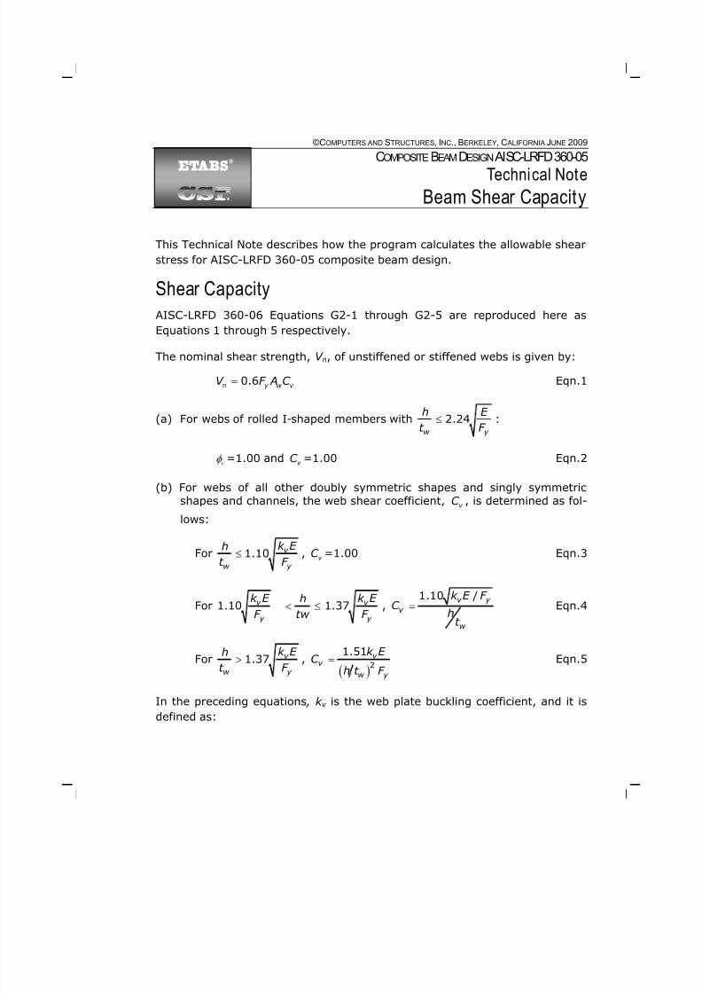
8/21/2019 Composit Beam
http://slidepdf.com/reader/full/composit-beam 127/161
©COMPUTERS AND STRUCTURES, INC., BERKELEY, C ALIFORNIA JUNE 2009
COMPOSITEBEAMDESIGN AISC-LRFD 360-05
Technical Note
Beam Shear Capacity
This Technical Note describes how the program calculates the allowable shear
stress for AISC-LRFD 360-05 composite beam design.
Shear Capacity
AISC-LRFD 360-06 Equations G2-1 through G2-5 are reproduced here as
Equations 1 through 5 respectively.
The nominal shear strength, V n, of unstiffened or stiffened webs is given by:
0.6n y w v V F A C Eqn.1
(a) For webs of rolled I-shaped members with 2.24w y
h E
t F :
v=1.00 and v C =1.00 Eqn.2
(b) For webs of all other doubly symmetric shapes and singly symmetric
shapes and channels, the web shear coefficient, v C , is determined as fol-
lows:
For 1.10 v
w y
k E h
t F , v C =1.00 Eqn.3
For 1.10 1.37v v
y y
k E k E h
F tw F ,
1.10 /v y
v
w
k E F C
ht
Eqn.4
For 1.37 v
w y
k E h
t F ,
21.51 v
v w y
k E C
h t F Eqn.5
In the preceding equations , k v is the web plate buckling coefficient, and it is
defined as:
8/21/2019 Composit Beam
http://slidepdf.com/reader/full/composit-beam 128/161
Beam Shear Capacity Composite Beam Design AISC-LRFD 360-05
Beam Shear Capacity Page 2 of 3
(i) For unstiffened webs with h /t w < 260, k v = 5
(ii) For stiffened webs,
2
55v k
ah
2
2605 for 3.0v
w
a ak or h h h t
where,
a = clear distance between transverse stiffeners, in.
h = for rolled shapes, the clear distance between flanges
less the fillet or corner radii, in.
Note that in preceding Equations, Aw , the area of the web, is calculated as
shown in Equation 4 where C top and C bot are the depths of copes, if any, at the
top and bottom of the beam section. The copes are specified in the over-
writes.
Aw = (d C top C bot) t w Eqn. 6
Checking the Beam Shear
The program checks the beam shear at the ends of the beam using Equation
7.
1.0u
v n
V
V Eqn. 7
where,
V u = The required shear strength, that is, the applied factored shear,kips.
V n = Shear capacity, kips. This term is calculated from Equation 1.
8/21/2019 Composit Beam
http://slidepdf.com/reader/full/composit-beam 129/161
Composite Beam Design AISC-LRFD 360-05 Beam Shear Capacity
Beam Shear Capacity Page 3 of 3
v = Resistance factor for shear, unitless.
Limi tations of Beam Shear Check
Following are some limitations of the program's beam shear check for com-
posite beams.
No check is made for shear on the net section considering the bolt holes.
No check is made for shear rupture on a beam with the top flange coped as
described in AISC-LRFD 360-05 specification.
Beam shear is checked only at the ends of the beam. In unusual cases,
where some of the load cases act downward and some act upward, the
maximum shear may occur elsewhere. For example, consider a beam that
has a uniform load acting downward over its entire length and a single con-
centrated load acting upward at the center. Assume that the magnitude of
the upward concentrated load is equal to the magnitude of the uniform load
times its length. In that case, the end reactions are zero, and the maximum
shear occurs at the center of the beam. The program will check the shear at
the ends of the beam in that case but not at the center.
8/21/2019 Composit Beam
http://slidepdf.com/reader/full/composit-beam 130/161
Overview Page 1 of 11
©COMPUTERS AND STRUCTURES, INC., BERKELEY, C ALIFORNIA JUNE 2009
COMPOSITEBEAMDESIGN AISC360-05/IBC2006
Technical Note
Floor Vibration
Overview
For AISC360-05/IBC2006, by default the program performs the floor vibration
check in accordance with AISC Steel Design Guide 11 (DG11). The program
calculates the first natural vibration frequency, estimated peak acceleration(in units of g), pa g , and acceleration limit, oa g , for each beam and reports
this information to determine the adequacy of a composite beam section.
The acceleration limit of any floor system can be achieved by limiting the vi-
bration characteristics of beams or girders. The program optimize the floor
vibration by limiting the estimated peak acceleration of each individual beams
only.
Excitation Types
The program supports the following excitation types:
Walking Excitation
The recommended walking excitation criterion, the method for estimating the
required floor properties and design procedure, was first proposed by Allen
and Murray (1993). In DG11, the criterion is based on the dynamic response
of steel beam floor systems to walking forces. The criterion can be used to
evaluate structural systems supporting offices, shopping malls, footbridges
and similar occupancies.
Rhythmic Excitation
The rhythmic excitation criterion is based on the dynamic response of the
structural system to rhythmic exercise forces distributed over all or part of
the floor. This criterion is used to evaluate structural systems supporting
aerobics, dancing, audience participation and similar events, assuming that
loading function is known.
8/21/2019 Composit Beam
http://slidepdf.com/reader/full/composit-beam 131/161
Composite Beam Design AISC360-05/IBC2006 Floor Vibration
Design for Walking Excitation Page 2 of 11
Walking near Sensitive Equipment
For sensitive equipment, a criterion is based on the vibrational velocitiesgiven in Table 6.1 of DG11. The following expression can be used to convert
given velocity, V , to the corresponding acceleration, a.
2a g fV g (DG11 Eqn. 6.1)
Design for Walking ExcitationEffective Panel Weight
The effective panel weights for the beam and girder panels modes are esti-
mated from the following equation:
W wBL (DG11 Eqn. 4.2)
where,
w = Supported weight per unit area
L = Beam or girder span
B = Effective width
For the beam panel mode, the effective width is
1 /4
2 3•FloorWidth j j s j j B C D D L (DG11 Eqn. 4.3a)
where,
j C = 2.0 for beams in most areas
= 1.0 for beams parallel to an interior edge
3 12s eD d n = Transformed slab moment of inertia per unit width
ed = Effective depth of concrete slab, taken as the depth of
concrete above the form deck plus one-half the depth of
the form deck
s c n E E = Modular ratio
sE = Modulus of elasticity of steel
c E = Modulus of elasticity of concrete j t D I S = Transformed beam moment of inertia per unit width
t I = Effective moment of inertia of T-beam
S = Beam spacing
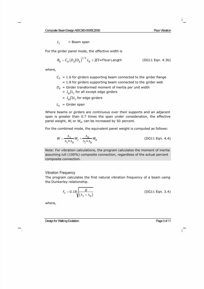
8/21/2019 Composit Beam
http://slidepdf.com/reader/full/composit-beam 132/161
Composite Beam Design AISC360-05/IBC2006 Floor Vibration
Design for Walking Excitation Page 3 of 11
j L = Beam span
For the girder panel mode, the effective width is
1 / 4
2 3•Floor Lengthg g j g gB C D D L (DG11 Eqn. 4.3b)
where,
C g = 1.6 for girders supporting beam connected to the girder flange
= 1.8 for girders supporting beam connected to the girder web
Dg = Girder transformed moment of inertia per unit width
= g j I L for all except edge girders
= 2g j I L for edge girders
Lg = Girder span
Where beams or girders are continuous over their supports and an adjacent
span is greater than 0.7 times the span under consideration, the effective
panel weight, W j or W g, can be increased by 50 percent.
For the combined mode, the equivalent panel weight is computed as follows:
j g j g+ +
j g j gW W W
(DG11 Eqn. 4.4)
Note: For vibration calculations, the program calculates the moment of inertia
assuming f ull (100%) composite connection, regardless of the actual percent
composite connection.
Vibration Frequency
The program calculates the first natural vibration frequency of a beam using
the Dunkerley relationship.
0.18
n j g
gf
(DG11 Eqn. 3.4)
where,
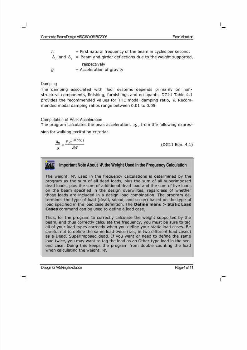
8/21/2019 Composit Beam
http://slidepdf.com/reader/full/composit-beam 133/161
Composite Beam Design AISC360-05/IBC2006 Floor Vibration
Design for Walking Excitation Page 4 of 11
f n = First natural frequency of the beam in cycles per second.
j and g
= Beam and girder deflections due to the weight supported,respectively
g = Acceleration of gravity
Damping
The damping associated with floor systems depends primarily on non-
structural components, finishing, furnishings and occupants. DG11 Table 4.1
provides the recommended values for THE modal damping ratio, . Recom-
mended modal damping ratios range between 0.01 to 0.05.
Computation of Peak AccelerationThe program calculates the peak acceleration, a , from the following expres-
sion for walking excitation criteria:
0.35 nf p oa P e
g W
(DG11 Eqn. 4.1)
Important Note About W , the Weight Used in the Frequency Calculation
The weight, W , used in the frequency calculations is determined by theprogram as the sum of all dead loads, plus the sum of all superimposeddead loads, plus the sum of additional dead load and the sum of live loads
on the beam specified in the design overwrites, regardless of whetherthose loads are included in a design load combination. The program de-
termines the type of load (dead, sdead, and so on) based on the type ofload specified in the load case definition. The Define menu > Static Load
Cases command can be used to define a load case.
Thus, for the program to correctly calculate the weight supported by the
beam, and thus correctly calculate the frequency, you must be sure to tagall of your load types correctly when you define your static load cases. Be
careful not to define the same load twice (i.e., in two different load cases)
as a Dead, Superimposed dead. If you want or need to define the sameload twice, you may want to tag the load as an Other-type load in the sec-ond case. Doing this keeps the program from double counting the load
when calculating the weight, W .
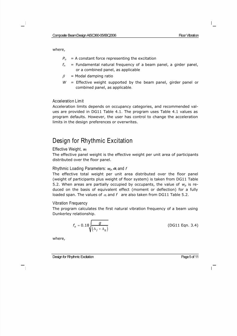
8/21/2019 Composit Beam
http://slidepdf.com/reader/full/composit-beam 134/161
Composite Beam Design AISC360-05/IBC2006 Floor Vibration
Design for Rhythmic Excitation Page 5 of 11
where,
P o = A constant force representing the excitation
f n = Fundamental natural frequency of a beam panel, a girder panel,
or a combined panel, as applicable
= Modal damping ratio
W = Effective weight supported by the beam panel, girder panel or
combined panel, as applicable.
Accelerat ion Limit
Acceleration limits depends on occupancy categories, and recommended val-
ues are provided in DG11 Table 4.1. The program uses Table 4.1 values asprogram defaults. However, the user has control to change the acceleration
limits in the design preferences or overwrites.
Design for Rhythmic ExcitationEffective Weight, w t
The effective panel weight is the effective weight per unit area of participants
distributed over the floor panel.
Rhythmic Loading Parameters: w p , i and f The effective total weight per unit area distributed over the floor panel
(weight of participants plus weight of floor system) is taken from DG11 Table
5.2. When areas are partially occupied by occupants, the value of w p is re-
duced on the basis of equivalent effect (moment or deflection) for a fully
loaded span. The values of i and f are also taken from DG11 Table 5.2.
Vibration Frequency
The program calculates the first natural vibration frequency of a beam using
Dunkerley relationship.
0.18n
j g
gf (DG11 Eqn. 3.4)
where,
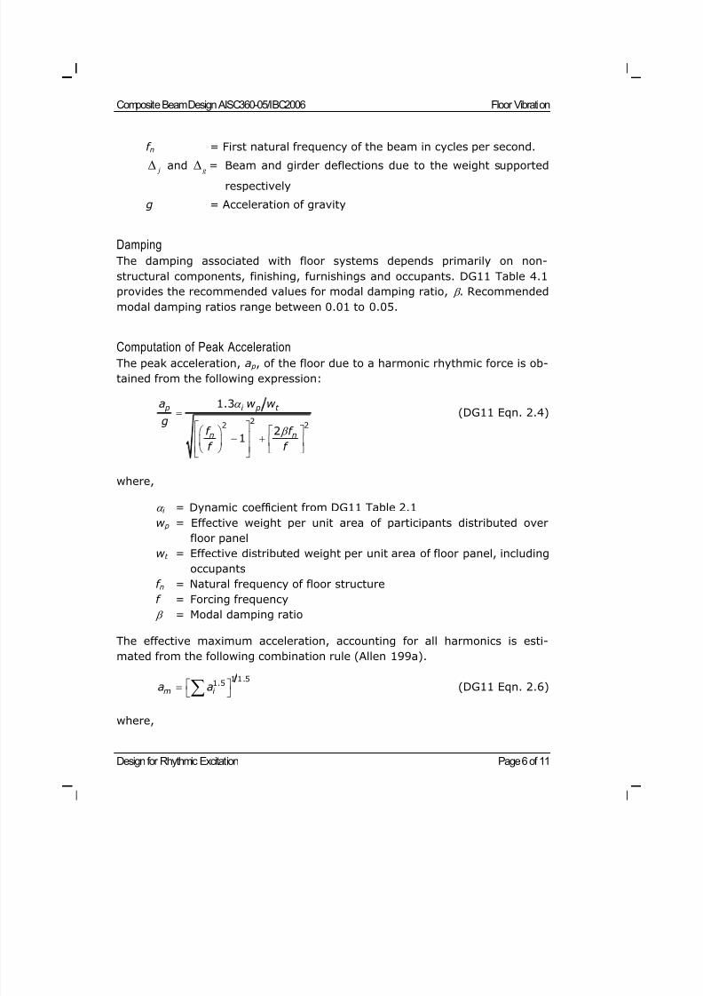
8/21/2019 Composit Beam
http://slidepdf.com/reader/full/composit-beam 135/161
Composite Beam Design AISC360-05/IBC2006 Floor Vibration
Design for Rhythmic Excitation Page 6 of 11
f n = First natural frequency of the beam in cycles per second.
j and g = Beam and girder deflections due to the weight supported
respectively
g = Acceleration of gravity
Damping
The damping associated with floor systems depends primarily on non-
structural components, finishing, furnishings and occupants. DG11 Table 4.1
provides the recommended values for modal damping ratio, . Recommended
modal damping ratios range between 0.01 to 0.05.
Computation of Peak Acceleration
The peak acceleration, a p, of the floor due to a harmonic rhythmic force is ob-
tained from the following expression:
22 2
1.3
21
p i p t
n n
a w w
gf f
f f
(DG11 Eqn. 2.4)
where,
i = Dynamic coefficient from DG11 Table 2.1
w p = Effective weight per unit area of participants distributed over
floor panel
w t = Effective distributed weight per unit area of floor panel, including
occupants
f n = Natural frequency of floor structure
f = Forcing frequency
= Modal damping ratio
The effective maximum acceleration, accounting for all harmonics is esti-
mated from the following combination rule (Allen 199a).
1 1.51.5
m i a a (DG11 Eqn. 2.6)
where,
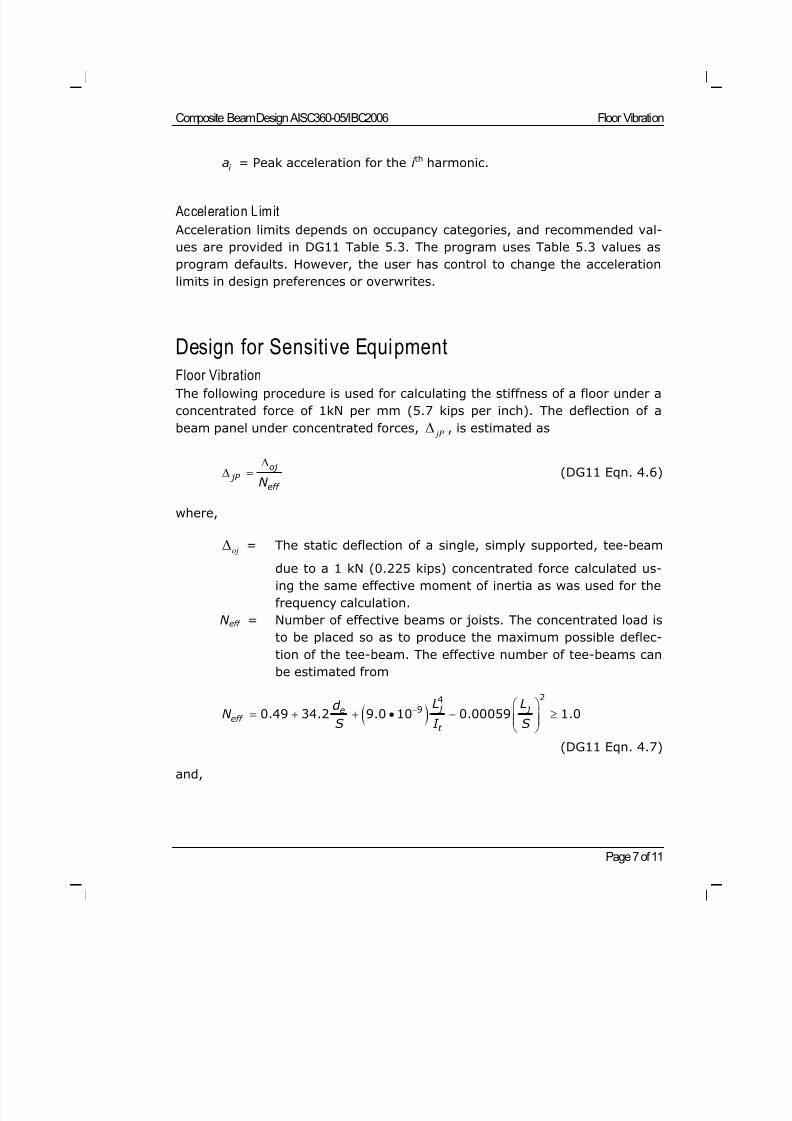
8/21/2019 Composit Beam
http://slidepdf.com/reader/full/composit-beam 136/161
Composite Beam Design AISC360-05/IBC2006 Floor Vibration
Page 7 of 11
i a = Peak acceleration for the i th harmonic.
Accelerat ion Limit
Acceleration limits depends on occupancy categories, and recommended val-
ues are provided in DG11 Table 5.3. The program uses Table 5.3 values as
program defaults. However, the user has control to change the acceleration
limits in design preferences or overwrites.
Design for Sensitive Equipment
Floor VibrationThe following procedure is used for calculating the stiffness of a floor under a
concentrated force of 1kN per mm (5.7 kips per inch). The deflection of a
beam panel under concentrated forces, jP
, is estimated as
oj jP
eff N
(DG11 Eqn. 4.6)
where,
oj = The static deflection of a single, simply supported, tee-beam
due to a 1 kN (0.225 kips) concentrated force calculated us-
ing the same effective moment of inertia as was used for the
frequency calculation.
N eff = Number of effective beams or joists. The concentrated load is
to be placed so as to produce the maximum possible deflec-
tion of the tee-beam. The effective number of tee-beams can
be estimated from
24
90.49 34.2 9.0 10 0.00059 1.0 j j e
eff t
L Ld N
S I S
(DG11 Eqn. 4.7)
and,
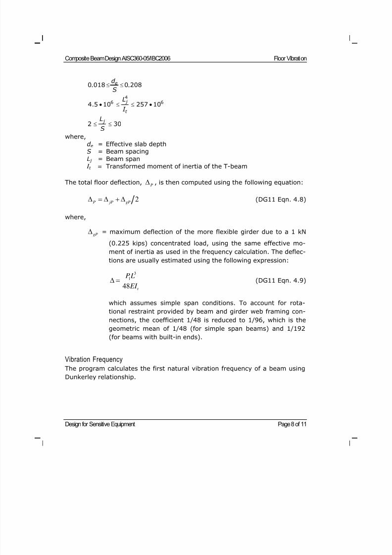
8/21/2019 Composit Beam
http://slidepdf.com/reader/full/composit-beam 137/161
Composite Beam Design AISC360-05/IBC2006 Floor Vibration
Design for Sensitive Equipment Page 8 of 11
0 018 0 208ed
S
. .
46 64.5 10 257 10
j
t
L
I
2 30 j L
S
where,
d e = Effective slab depthS = Beam spacing
L j = Beam span I t = Transformed moment of inertia of the T-beam
The total floor deflection,P
, is then computed using the following equation:
2P jP gP
(DG11 Eqn. 4.8)
where,
gP = maximum deflection of the more flexible girder due to a 1 kN
(0.225 kips) concentrated load, using the same effective mo-
ment of inertia as used in the frequency calculation. The deflec-
tions are usually estimated using the following expression:
3
1
48 t
P L EI (DG11 Eqn. 4.9)
which assumes simple span conditions. To account for rota-
tional restraint provided by beam and girder web framing con-
nections, the coefficient 1/48 is reduced to 1/96, which is the
geometric mean of 1/48 (for simple span beams) and 1/192
(for beams with built-in ends).
Vibration Frequency
The program calculates the first natural vibration frequency of a beam using
Dunkerley relationship.
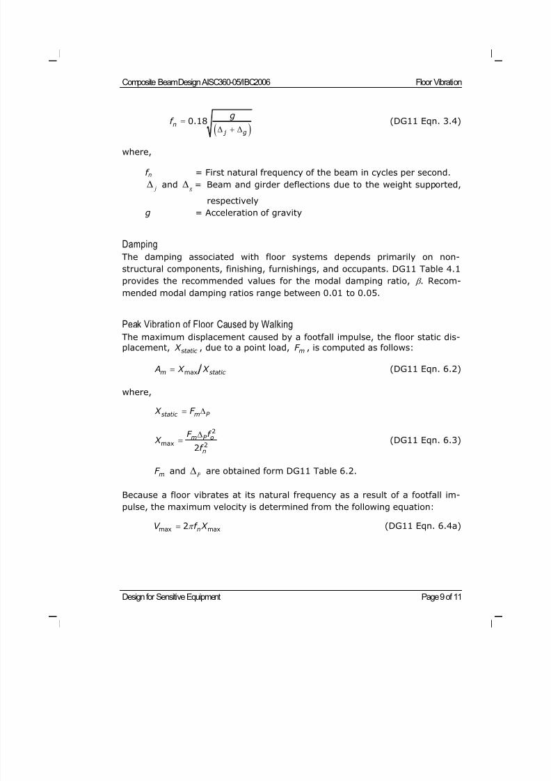
8/21/2019 Composit Beam
http://slidepdf.com/reader/full/composit-beam 138/161
Composite Beam Design AISC360-05/IBC2006 Floor Vibration
Design for Sensitive Equipment Page 9 of 11
0.18n
j g
gf
(DG11 Eqn. 3.4)
where,
f n = First natural frequency of the beam in cycles per second.
j and
g = Beam and girder deflections due to the weight supported,
respectively
g = Acceleration of gravity
Damping
The damping associated with floor systems depends primarily on non-
structural components, finishing, furnishings, and occupants. DG11 Table 4.1
provides the recommended values for the modal damping ratio, . Recom-
mended modal damping ratios range between 0.01 to 0.05.
Peak Vibration of Floor Caused by Walking
The maximum displacement caused by a footfall impulse, the floor static dis-
placement, static X , due to a point load, mF , is computed as follows:
maxm static A X X (DG11 Eqn. 6.2)
where,
static m P X F
2
max 22
m P o
n
F f X
f
(DG11 Eqn. 6.3)
mF andP
are obtained form DG11 Table 6.2.
Because a floor vibrates at its natural frequency as a result of a footfall im-
pulse, the maximum velocity is determined from the following equation:
max max2 nV f X (DG11 Eqn. 6.4a)
8/21/2019 Composit Beam
http://slidepdf.com/reader/full/composit-beam 139/161
Composite Beam Design AISC360-05/IBC2006 Floor Vibration
References Page 10 of 11
Vibrational Velocity Limi t for Sensitive Equipment
For sensitive equipment, a criterion is based on the vibrational velocitiesgiven in Table 6.1 of DG11. The following expression can be used to convert
given velocity, V , to the corresponding acceleration, a.
2a g fV g (DG11 Eqn. 6.1)
References
Allen, D.L. 1974. Vibrational Behavior of Long Span Floor Slabs. Canadian
Journal of Civil Engineering. Vol. 1, No. 1. September.
Allen, D. E., and J.H. Rainer. 1976. Vibration Criteria for Long Span Floors.
Canadian Journal of Civil Engineering. Vol. 3, No.2. June.
Allen, D.E., J.H. Rainer, and G. Pernica. 1979. Vibration Criteria for Long Span
Concrete Floors. Vibrations of Concrete Structures. Publication SP-60.
American Concrete Institute. Detroit, MI.
Allen, D. E. and Murray, T. M., 1993, "Design Criterion for Vibrations due to
Walking," Engineering Journal, 4th Qtr, AISC, pp. 117-129.
Murray, T. M., Allen, D. E. and Unger, E. E., 1997, "Floor Vibrations due to
Human Activity," AISC Steel Design Guide Series 11.
Murray, T.H. 1975. Design to Prevent Floor Vibration. Engineering Journal .
American Institute of Steel Construction, Inc. Vol. 12, No. 3.
Murray, T.H. 1981. Acceptability Criterion for Occupant-Induced Floor Vibra-
tions. Engineering Journal. American Institute of Steel Construction,
Inc. Vol. 18, No. 2.
Murray, T.M. 1991. Building Floor Vibrations. Engineering Journal. American
Institute of Steel Construction, Inc. Vol. 28, No. 3.
Murray, T.M. and W.E. Hendrick. 1977. Floor Vibrations and CantileveredConstruction. Engineering Journal . American Steel Institute of Steel
Construction, Inc. Vol. 14, No. 3.
8/21/2019 Composit Beam
http://slidepdf.com/reader/full/composit-beam 140/161
Composite Beam Design AISC360-05/IBC2006 Floor Vibration
References Page 11 of 11
Naeim, F. 1991. Design Practice to Prevent Floor Vibration. Steel Tips, Techni-
cal Information & Product Service. Structural Steel Educational Coun-cil. September.
8/21/2019 Composit Beam
http://slidepdf.com/reader/full/composit-beam 141/161
Input Data Page 1 of 7
©COMPUTERS AND STRUCTURES, INC., BERKELEY, C ALIFORNIA DECEMBER 2008
COMPOSITEBEAMDESIGN AISC-LRFD 360-05
Technical Note
Input Data
This Technical Note describes the composite beam design input data for AISC-
LRFD 360-05. The input can be printed to a printer or to a text file when you
click the File menu > Print Tables > Composite Beam Design command.
A printout of the input data provides the user with the opportunity to carefully
review the parameters that have been input into the program and upon which
program design is based. See Composite Beam Design Technical Note Input
Data for further information about using the print Composite Beam Design
Tables Form, as well as other non-code-specific input data for composite
beam design.
Beam Overwrites Input Data
The program provides the printout of the input data in a series of tables. The
tables typically correspond to the tabs used in the Composite Beam Over-
writes form. The column headings for input data and a description of what is
included in the columns of the tables are provided in Table 1 of this Technical
Note.
Recall that the composite beam overwrites apply to all beams to which they
have been specifically assigned. To access the composite beam overwrites,
select one or more beams and then click the Design menu > Composite
Beam Design > View/Revise Overwrites command. Information about
composite beam overwrites is available in Composite Beam Design AISC-LRFD
360-05 Technical Note Overwrites.
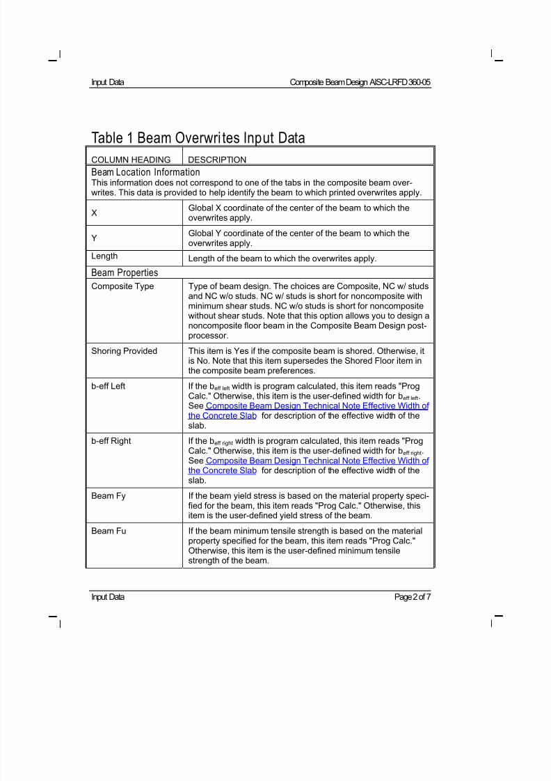
8/21/2019 Composit Beam
http://slidepdf.com/reader/full/composit-beam 142/161
Input Data Composite Beam Design AISC-LRFD 360-05
Input Data Page 2 of 7
Table 1 Beam Overwri tes Input Data
COLUMN HEADING DESCRIPTION
Beam Location InformationThis information does not correspond to one of the tabs in the composite beam over-writes. This data is provided to help identify the beam to which printed overwrites apply.
XGlobal X coordinate of the center of the beam to which theoverwrites apply.
YGlobal Y coordinate of the center of the beam to which theoverwrites apply.
LengthLength of the beam to which the overwrites apply.
Beam Properties
Composite Type Type of beam design. The choices are Composite, NC w/ studsand NC w/o studs. NC w/ studs is short for noncomposite withminimum shear studs. NC w/o studs is short for noncompositewithout shear studs. Note that this option allows you to design anoncomposite floor beam in the Composite Beam Design post-processor.
Shoring Provided This item is Yes if the composite beam is shored. Otherwise, itis No. Note that this item supersedes the Shored Floor item inthe composite beam preferences.
b-eff Left If the beff left width is program calculated, this item reads "ProgCalc." Otherwise, this item is the user-defined width for beff left.See Composite Beam Design Technical Note Effective Width ofthe Concrete Slab for description of the effective width of theslab.
b-eff Right If the beff right width is program calculated, this item reads "ProgCalc." Otherwise, this item is the user-defined width for beff right.See Composite Beam Design Technical Note Effective Width ofthe Concrete Slab for description of the effective width of theslab.
Beam Fy If the beam yield stress is based on the material property speci-fied for the beam, this item reads "Prog Calc." Otherwise, thisitem is the user-defined yield stress of the beam.
Beam Fu If the beam minimum tensile strength is based on the materialproperty specified for the beam, this item reads "Prog Calc."Otherwise, this item is the user-defined minimum tensilestrength of the beam.
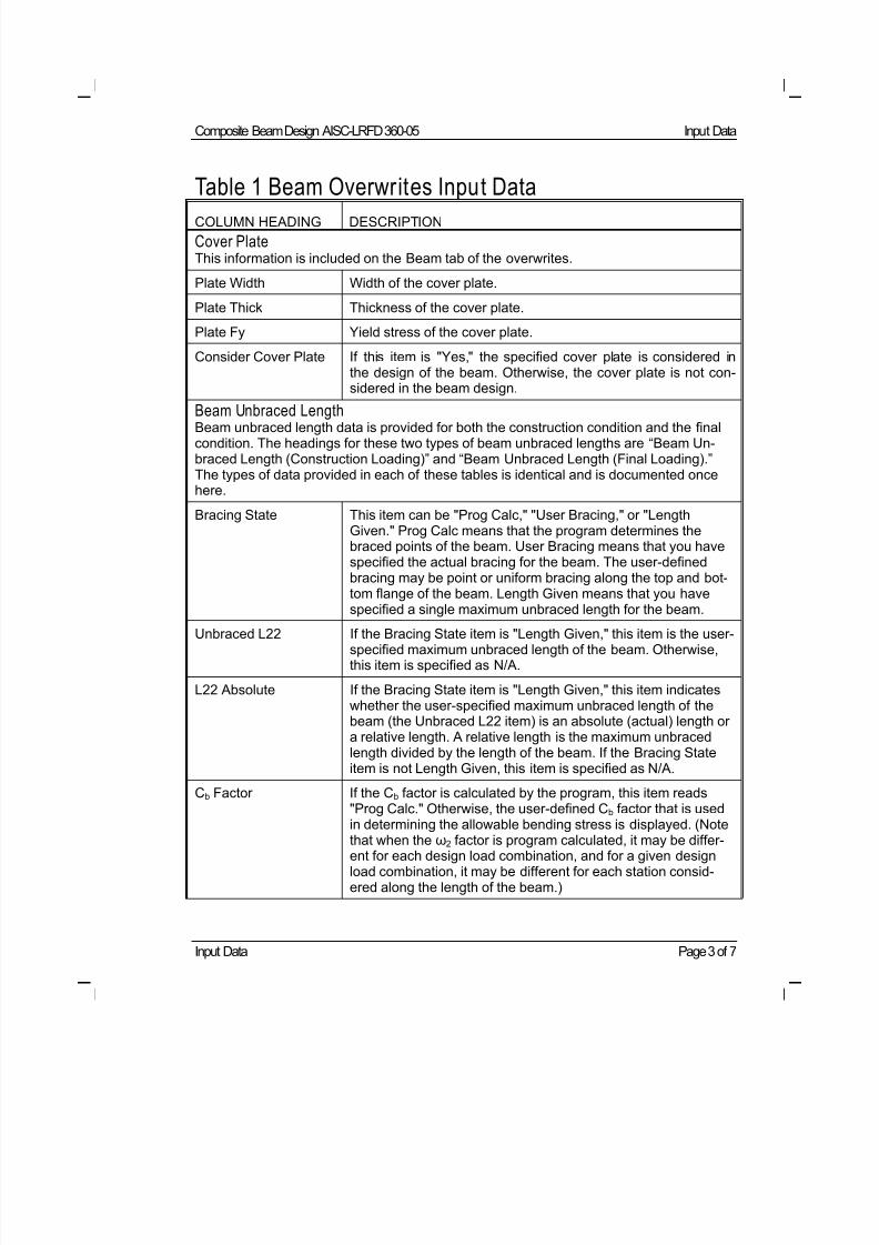
8/21/2019 Composit Beam
http://slidepdf.com/reader/full/composit-beam 143/161
Composite Beam Design AISC-LRFD 360-05 Input Data
Input Data Page 3 of 7
Table 1 Beam Overwrites Input Data
COLUMN HEADING DESCRIPTION
Cover PlateThis information is included on the Beam tab of the overwrites.
Plate Width Width of the cover plate.
Plate Thick Thickness of the cover plate.
Plate Fy Yield stress of the cover plate.
Consider Cover Plate If this item is "Yes," the specified cover plate is considered inthe design of the beam. Otherwise, the cover plate is not con-sidered in the beam design.
Beam Unbraced LengthBeam unbraced length data is provided for both the construction condition and the finalcondition. The headings for these two types of beam unbraced lengths are “Beam Un-braced Length (Construction Loading)” and “Beam Unbraced Length (Final Loading).”The types of data provided in each of these tables is identical and is documented oncehere.
Bracing State This item can be "Prog Calc," "User Bracing," or "LengthGiven." Prog Calc means that the program determines thebraced points of the beam. User Bracing means that you havespecified the actual bracing for the beam. The user-definedbracing may be point or uniform bracing along the top and bot-tom flange of the beam. Length Given means that you havespecified a single maximum unbraced length for the beam.
Unbraced L22 If the Bracing State item is "Length Given," this item is the user-specified maximum unbraced length of the beam. Otherwise,this item is specified as N/A.
L22 Absolute If the Bracing State item is "Length Given," this item indicateswhether the user-specified maximum unbraced length of thebeam (the Unbraced L22 item) is an absolute (actual) length ora relative length. A relative length is the maximum unbracedlength divided by the length of the beam. If the Bracing Stateitem is not Length Given, this item is specified as N/A.
Cb Factor If the Cb factor is calculated by the program, this item reads"Prog Calc." Otherwise, the user-defined Cb factor that is usedin determining the allowable bending stress is displayed. (Notethat when the ω2 factor is program calculated, it may be differ-ent for each design load combination, and for a given designload combination, it may be different for each station consid-ered along the length of the beam.)
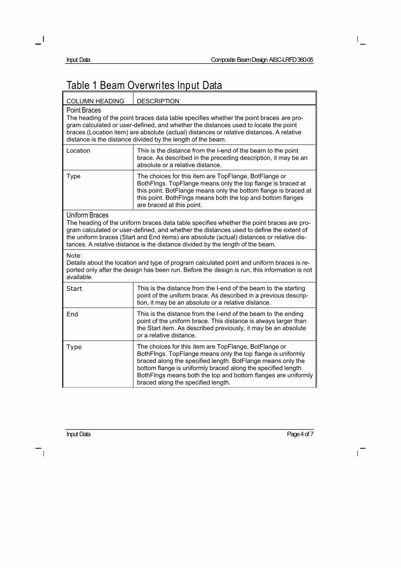
8/21/2019 Composit Beam
http://slidepdf.com/reader/full/composit-beam 144/161
Input Data Composite Beam Design AISC-LRFD 360-05
Input Data Page 4 of 7
Table 1 Beam Overwri tes Input Data
COLUMN HEADING DESCRIPTION
Point Braces
The heading of the point braces data table specifies whether the point braces are pro-gram calculated or user-defined, and whether the distances used to locate the pointbraces (Location item) are absolute (actual) distances or relative distances. A relativedistance is the distance divided by the length of the beam.
Location This is the distance from the I-end of the beam to the pointbrace. As described in the preceding description, it may be anabsolute or a relative distance.
Type The choices for this item are TopFlange, BotFlange orBothFlngs. TopFlange means only the top flange is braced at
this point. BotFlange means only the bottom flange is braced atthis point. BothFlngs means both the top and bottom flangesare braced at this point.
Uniform Braces
The heading of the uniform braces data table specifies whether the point braces are pro-gram calculated or user-defined, and whether the distances used to define the extent ofthe uniform braces (Start and End items) are absolute (actual) distances or relative dis-tances. A relative distance is the distance divided by the length of the beam.
Note:Details about the location and type of program calculated point and uniform braces is re-ported only after the design has been run. Before the design is run, this information is notavailable.
Start This is the distance from the I-end of the beam to the startingpoint of the uniform brace. As described in a previous descrip-tion, it may be an absolute or a relative distance.
End This is the distance from the I-end of the beam to the endingpoint of the uniform brace. This distance is always larger thanthe Start item. As described previously, it may be an absoluteor a relative distance.
Type The choices for this item are TopFlange, BotFlange orBothFlngs. TopFlange means only the top flange is uniformlybraced along the specified length. BotFlange means only thebottom flange is uniformly braced along the specified length.BothFlngs means both the top and bottom flanges are uniformly
braced along the specified length.
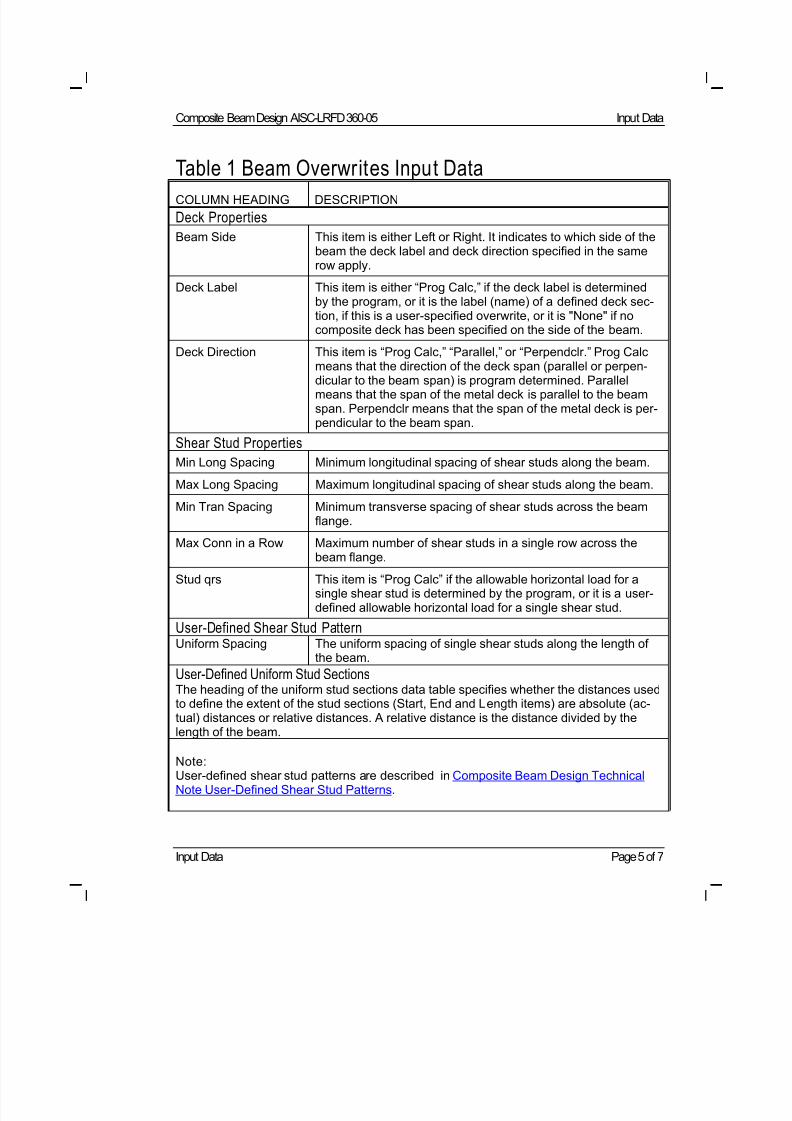
8/21/2019 Composit Beam
http://slidepdf.com/reader/full/composit-beam 145/161
Composite Beam Design AISC-LRFD 360-05 Input Data
Input Data Page 5 of 7
Table 1 Beam Overwrites Input Data
COLUMN HEADING DESCRIPTION
Deck Properties
Beam Side This item is either Left or Right. It indicates to which side of thebeam the deck label and deck direction specified in the samerow apply.
Deck Label This item is either “Prog Calc,” if the deck label is determinedby the program, or it is the label (name) of a defined deck sec-tion, if this is a user-specified overwrite, or it is "None" if nocomposite deck has been specified on the side of the beam.
Deck Direction This item is “Prog Calc,” “Parallel,” or “Perpendclr.” Prog Calcmeans that the direction of the deck span (parallel or perpen-dicular to the beam span) is program determined. Parallelmeans that the span of the metal deck is parallel to the beamspan. Perpendclr means that the span of the metal deck is per-pendicular to the beam span.
Shear Stud Properties
Min Long Spacing Minimum longitudinal spacing of shear studs along the beam.
Max Long Spacing Maximum longitudinal spacing of shear studs along the beam.
Min Tran Spacing Minimum transverse spacing of shear studs across the beamflange.
Max Conn in a Row Maximum number of shear studs in a single row across the
beam flange.Stud qrs This item is “Prog Calc” if the allowable horizontal load for a
single shear stud is determined by the program, or it is a user-defined allowable horizontal load for a single shear stud.
User-Defined Shear Stud PatternUniform Spacing The uniform spacing of single shear studs along the length of
the beam.
User-Defined Uniform Stud Sections
The heading of the uniform stud sections data table specifies whether the distances usedto define the extent of the stud sections (Start, End and Length items) are absolute (ac-tual) distances or relative distances. A relative distance is the distance divided by thelength of the beam.
Note: User-defined shear stud patterns are described in Composite Beam Design TechnicalNote User-Defined Shear Stud Patterns.
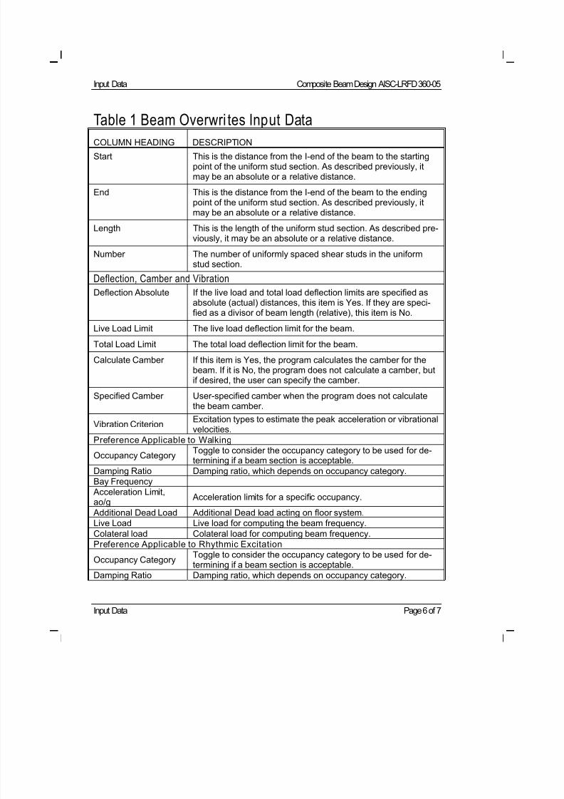
8/21/2019 Composit Beam
http://slidepdf.com/reader/full/composit-beam 146/161
Input Data Composite Beam Design AISC-LRFD 360-05
Input Data Page 6 of 7
Table 1 Beam Overwri tes Input Data
COLUMN HEADING DESCRIPTION
Start This is the distance from the I-end of the beam to the startingpoint of the uniform stud section. As described previously, itmay be an absolute or a relative distance.
End This is the distance from the I-end of the beam to the endingpoint of the uniform stud section. As described previously, itmay be an absolute or a relative distance.
Length This is the length of the uniform stud section. As described pre-viously, it may be an absolute or a relative distance.
Number The number of uniformly spaced shear studs in the uniform
stud section. Deflection, Camber and Vibration
Deflection Absolute If the live load and total load deflection limits are specified asabsolute (actual) distances, this item is Yes. If they are speci-fied as a divisor of beam length (relative), this item is No.
Live Load Limit The live load deflection limit for the beam.
Total Load Limit The total load deflection limit for the beam.
Calculate Camber If this item is Yes, the program calculates the camber for thebeam. If it is No, the program does not calculate a camber, butif desired, the user can specify the camber.
Specified Camber User-specified camber when the program does not calculatethe beam camber.
Vibration CriterionExcitation types to estimate the peak acceleration or vibrationalvelocities.
Preference Applicable to Walking
Occupancy CategoryToggle to consider the occupancy category to be used for de-termining if a beam section is acceptable.
Damping Ratio Damping ratio, which depends on occupancy category.
Bay Frequency
Acceleration Limit,ao/g
Acceleration limits for a specific occupancy.
Additional Dead Load Additional Dead load acting on floor system.
Live Load Live load for computing the beam frequency.
Colateral load Colateral load for computing beam frequency.Preference Applicable to Rhythmic Excitation
Occupancy CategoryToggle to consider the occupancy category to be used for de-termining if a beam section is acceptable.
Damping Ratio Damping ratio, which depends on occupancy category.
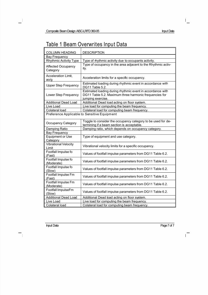
8/21/2019 Composit Beam
http://slidepdf.com/reader/full/composit-beam 147/161
Composite Beam Design AISC-LRFD 360-05 Input Data
Input Data Page 7 of 7
Table 1 Beam Overwrites Input Data
COLUMN HEADING DESCRIPTION
Bay Frequency
Rhythmic Activity Type Type of rhythmic activity due to occupants activity.
Affected OccupancyCategory
Type of occupancy in the area adjacent to the Rhythmic activ-ity.
Acceleration Limit,ao/g
Acceleration limits for a specific occupancy.
Upper Step FrequencyEstimated loading during rhythmic event in accordance withDG11 Table 5.2.
Lower Step FrequencyEstimated loading during rhythmic event in accordance withDG11 Table 5.2. Maximum three harmonic frequencies for
jumping exercise. Additional Dead Load Additional Dead load acting on floor system.
Live Load Live load for computing the beam frequency.
Colateral load Colateral load for computing beam frequency.
Preference Applicable to Sensitive Equipment
Occupancy CategoryToggle to consider the occupancy category to be used for de-termining if a beam section is acceptable.
Damping Ratio Damping ratio, which depends on occupancy category.
Bay Frequency
Equipment or UseCategory
Type of equipment and use category.
Vibrational Velocity
LimitVibrational velocity limits for a specific occupancy.
Footfall Impulse fo(Fast)
Values of footfall impulse parameters from DG11 Table 6.2.
Footfall Impulse fo(Moderate)
Values of footfall impulse parameters from DG11 Table 6.2.
Footfall Impulse fo(Slow)
Values of footfall impulse parameters from DG11 Table 6.2.
Footfall Impulse Fm(Fast)
Values of footfall impulse parameters from DG11 Table 6.2.
Footfall Impulse Fm(Moderate)
Values of footfall impulse parameters from DG11 Table 6.2.
Footfall ImpulseFm(Slow)
Values of footfall impulse parameters from DG11 Table 6.2.
Additional Dead Load Additional Dead load acting on floor system.Live Load Live load for computing the beam frequency.
Colateral load Colateral load for computing beam frequency.
8/21/2019 Composit Beam
http://slidepdf.com/reader/full/composit-beam 148/161
Output Details Page 1 of 14
©COMPUTERS AND STRUCTURES, INC., BERKELEY, C ALIFORNIA DECEMBER 2008
COMPOSITEBEAMDESIGN AISC-LRFD 360-05
Technical Note
Output Details
This Technical Note describes the composite beam output for AISC-LRFD 360-
05 that can be printed to a printer or to a text file in short form or long form.
See Composite Beam Design Technical Note Output Data for information
about using the Print Composite Beam Design Tables Form, as well as the
Summary of Composite Beam Output.
The program provides the output data in a series of tables. The column head-ings for output data and a description of what is included in the columns of
the tables are provided in Tables 1 and 2 of this Technical Note.
Short Form Output Details
This output is printed when you click the File menu > Print Tables > Com-
posite Beam Design command and select Short Form in the Output Details
area of the resulting form. Similar output also appears on screen if you click
the Details button in the Show Details area of the Interactive Composite
Beam Design and Review form. See Composite Beam Design Technical Note
Interactive Composite Beam Design for more details on the interactive design.
Table 1 Output Details - Short Form
COLUMN HEADING DESCRIPTION
Basic Beam Information
Beam Label Label associated with the line object that represents the beam. A typical beam label would appear as "B23." Do not confusethis with the Section Label, which would be identified as"W610X82."
Group Name of the design group (if any) to which the beam has been
assigned.
Beam Beam section label (name).
8/21/2019 Composit Beam
http://slidepdf.com/reader/full/composit-beam 149/161
Composite Beam Design AISC-LRFD 360-05 Output Details
Output Details Page 2 of 14
Table 1 Output Details - Short Form
COLUMN HEADING DESCRIPTION
Fy Beam yield stress, Fy.
Fu Beam minimum tensile strength, Fu.
Stud Layout Number of studs in each composite beam segment separatedby commas. They are listed starting with the composite beamsegment at the I-end of the beam and working toward the J-endof the beam.
Seg. Length Length of each composite beam segment separated by com-mas. The lengths are listed starting with the composite beamsegment at the I-end of the beam and working toward the J-endof the beam.
Stud Ratio This item has a slightly different meaning, depending onwhether the shear studs are user-defined or calculated by theprogram.
When the number of shear studs is calculated by the program,a stud ratio is reported for each composite beam segment. It isequal to the number of shear studs required in the segmentdivided by the maximum number of studs that fit in the seg-ment.
When the shear studs are user-defined, a single stud ratio isreported for the entire beam. At each output station considered(i.e., at each maximum moment or point load location), the pro-gram calculates the number of shear studs required betweenthe output station and adjacent points of zero moment, end ofthe beam top flange, or end of the concrete slab. The programthen divides this number of required shear studs by the speci-fied number of shear studs to obtain a ratio. The maximum ratioobtained at any considered output station for any design loadcase is reported as the stud ratio.
Story Story level associated with the beam.
Length Length of the beam.
Loc X Global X coordinate of the center of the beam.
8/21/2019 Composit Beam
http://slidepdf.com/reader/full/composit-beam 150/161
Composite Beam Design AISC-LRFD 360-05 Output Details
Output Details Page 3 of 14
Table 1 Output Details - Short Form
COLUMN HEADING DESCRIPTION
Loc Y Global Y coordinate of the center of the beam.
RLLF A reducible live load is multiplied by this factor to obtain the re-duced live load.
Shored This item is Yes if the beam is shored and No if it is unshored.
Camber The camber for the beam. This item may be calculated by theprogram or it may be user-specified.
Comparative Price of the beam using the input price parameters for steel,shear studs and camber. This price is intended for comparisonof alternative designs only. It is not intended to be used for costestimating purposes.
Stud Diam Diameter of shear studs.
Overwrites If this item is Yes, one or more items have been overwritten forthis beam. If it is No, nothing has been overwritten. The valuesfor all overwrite items are included in the long form output.Thus, if this item is "Yes," you may want to print the long formoutput.
b-cp Width of the cover plate. If no cover plate is specified by theuser, N/A is reported for this item.
t-cp Thickness of the cover plate. If no cover plate is specified bythe user, N/A is reported for this item.
Fy-cp Yield stress for the cover plate. If no cover plate is specified bythe user, N/A is reported for this item.
Consider-cp This item is Yes if the specified cover plate is considered in thedesign. Otherwise, it is No.
Deck Left and Deck
Right
The deck section labels (names) on the left and right sides of
the beam.
8/21/2019 Composit Beam
http://slidepdf.com/reader/full/composit-beam 151/161
Composite Beam Design AISC-LRFD 360-05 Output Details
Output Details Page 4 of 14
Table 1 Output Details - Short Form
COLUMN HEADING DESCRIPTION
Dir. Left and Dir. Right The deck directions on the left and right sides of the beam.Perpendclr means that the deck span is perpendicular to thebeam span. Parallel means that the deck span is parallel to thebeam span.
beff Left and beff Right The slab effective widths on the left and right sides of the beam.
Ctop Left and CtopRight
The program calculated cope of the beam top flange at the leftand right ends of the beam. Do not confuse the left and rightends of the beam with the left and right sides of the beam. Theleft end of the beam is the I-end and the right end of the beamis the J-end.
Cbot Left and CbotRight
The program calculated cope of the beam bottom flange at theleft and right ends of the beam. Do not confuse the left and rightends of the beam with the left and right sides of the beam. Theleft end of the beam is the I-end and the right end of the beamis the J-end.
Itrans Transformed section moment of inertia for full (100%) compos-ite connection for positive bending, Itr .
Ibare Moment of inertia of the steel beam, including cover plate, if itexists.
Is Moment of inertia of the steel beam alone, not including coverplate, even if it exists.
Ieff Effective moment of inertia for partial composite connection.
PCC Percent composite connection.
ytrans Distance from the bottom of the beam bottom flange (not bot-tom of cover plate, even if it exists) to the elastic neutral axis
(ENA) of the beam, with full (100%) composite connection, y .
ybare Distance from the bottom of the beam bottom flange (not bot-tom of cover plate, even if it exists) to the ENA of the beam,plus cover plate alone (if it exists).
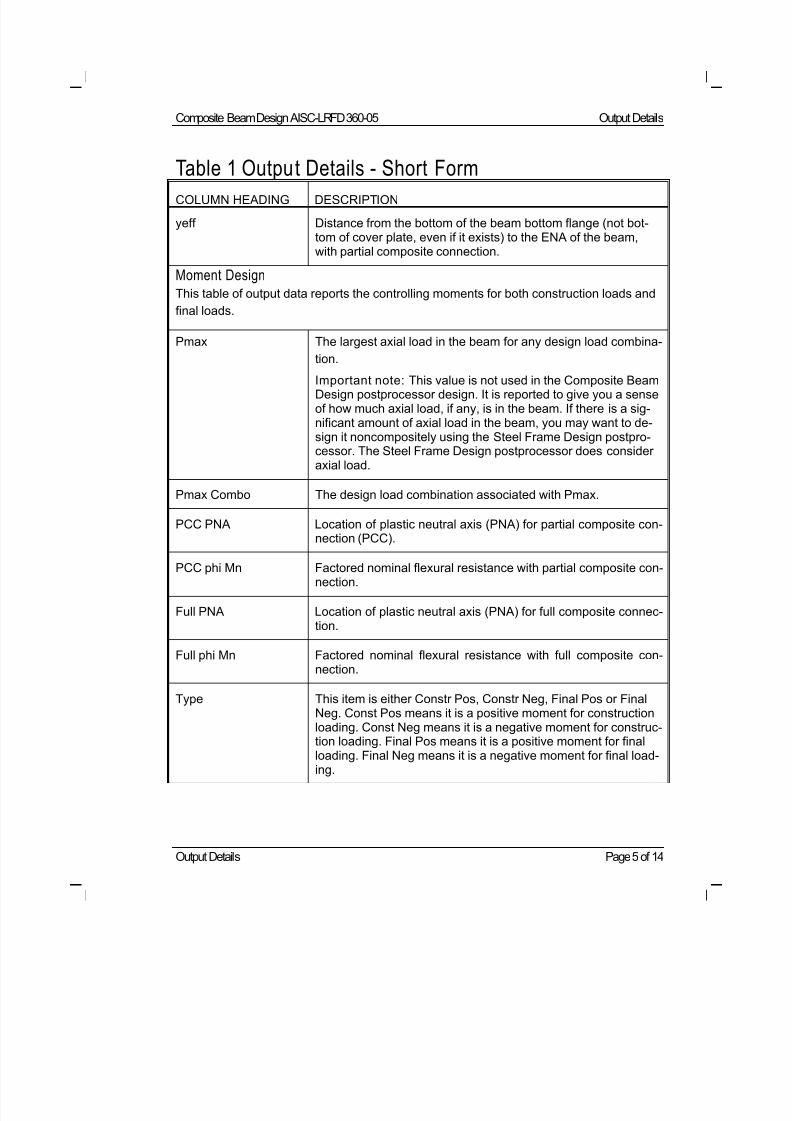
8/21/2019 Composit Beam
http://slidepdf.com/reader/full/composit-beam 152/161
Composite Beam Design AISC-LRFD 360-05 Output Details
Output Details Page 5 of 14
Table 1 Output Details - Short Form
COLUMN HEADING DESCRIPTION
yeff Distance from the bottom of the beam bottom flange (not bot-tom of cover plate, even if it exists) to the ENA of the beam,with partial composite connection.
Moment Design
This table of output data reports the controlling moments for both construction loads and
final loads.
Pmax The largest axial load in the beam for any design load combina-
tion.
Important note: This value is not used in the Composite BeamDesign postprocessor design. It is reported to give you a senseof how much axial load, if any, is in the beam. If there is a sig-nificant amount of axial load in the beam, you may want to de-sign it noncompositely using the Steel Frame Design postpro-cessor. The Steel Frame Design postprocessor does consideraxial load.
Pmax Combo The design load combination associated with Pmax.
PCC PNA Location of plastic neutral axis (PNA) for partial composite con-nection (PCC).
PCC phi Mn Factored nominal flexural resistance with partial composite con-nection.
Full PNA Location of plastic neutral axis (PNA) for full composite connec-tion.
Full phi Mn Factored nominal flexural resistance with full composite con-nection.
Type This item is either Constr Pos, Constr Neg, Final Pos or FinalNeg. Const Pos means it is a positive moment for constructionloading. Const Neg means it is a negative moment for construc-tion loading. Final Pos means it is a positive moment for final
loading. Final Neg means it is a negative moment for final load-ing.
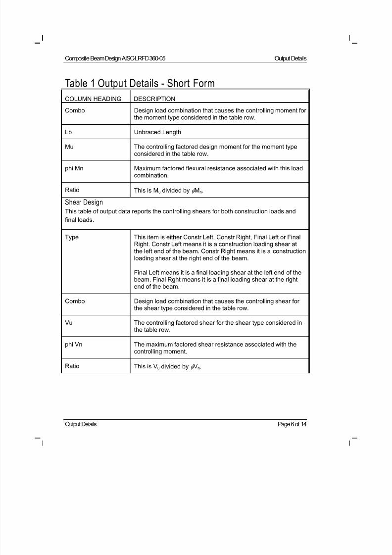
8/21/2019 Composit Beam
http://slidepdf.com/reader/full/composit-beam 153/161
Composite Beam Design AISC-LRFD 360-05 Output Details
Output Details Page 6 of 14
Table 1 Output Details - Short Form
COLUMN HEADING DESCRIPTION
Combo Design load combination that causes the controlling moment forthe moment type considered in the table row.
Lb Unbraced Length
Mu The controlling factored design moment for the moment typeconsidered in the table row.
phi Mn Maximum factored flexural resistance associated with this loadcombination.
Ratio This is Mu divided by Mn.
Shear Design
This table of output data reports the controlling shears for both construction loads and
final loads.
Type This item is either Constr Left, Constr Right, Final Left or FinalRight. Constr Left means it is a construction loading shear atthe left end of the beam. Constr Right means it is a constructionloading shear at the right end of the beam.
Final Left means it is a final loading shear at the left end of the
beam. Final Rght means it is a final loading shear at the rightend of the beam.
Combo Design load combination that causes the controlling shear forthe shear type considered in the table row.
Vu The controlling factored shear for the shear type considered inthe table row.
phi Vn The maximum factored shear resistance associated with thecontrolling moment.
Ratio This is Vu divided by Vn.
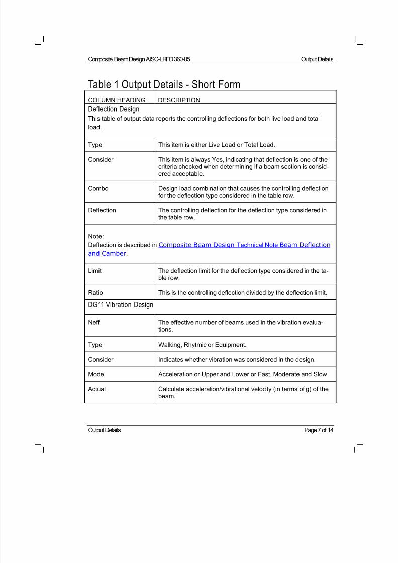
8/21/2019 Composit Beam
http://slidepdf.com/reader/full/composit-beam 154/161
Composite Beam Design AISC-LRFD 360-05 Output Details
Output Details Page 7 of 14
Table 1 Output Details - Short Form
COLUMN HEADING DESCRIPTION
Deflection Design
This table of output data reports the controlling deflections for both live load and total
load.
Type This item is either Live Load or Total Load.
Consider This item is always Yes, indicating that deflection is one of thecriteria checked when determining if a beam section is consid-ered acceptable.
Combo Design load combination that causes the controlling deflectionfor the deflection type considered in the table row.
Deflection The controlling deflection for the deflection type considered inthe table row.
Note:
Deflection is described in Composite Beam Design Technical Note Beam Deflection
and Camber.
Limit The deflection limit for the deflection type considered in the ta-ble row.
Ratio This is the controlling deflection divided by the deflection limit.
DG11 Vibration Design
Neff The effective number of beams used in the vibration evalua-tions.
Type Walking, Rhytmic or Equipment.
Consider Indicates whether vibration was considered in the design.
Mode Acceleration or Upper and Lower or Fast, Moderate and Slow
Actual Calculate acceleration/vibrational velocity (in terms of g) of thebeam.
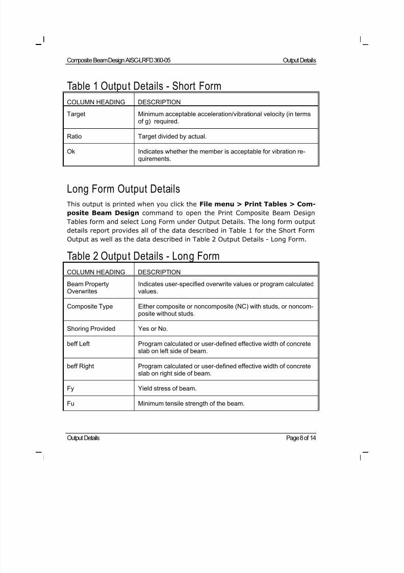
8/21/2019 Composit Beam
http://slidepdf.com/reader/full/composit-beam 155/161
Composite Beam Design AISC-LRFD 360-05 Output Details
Output Details Page 8 of 14
Table 1 Output Details - Short Form
COLUMN HEADING DESCRIPTION
Target Minimum acceptable acceleration/vibrational velocity (in termsof g) required.
Ratio Target divided by actual.
Ok Indicates whether the member is acceptable for vibration re-quirements.
Long Form Output DetailsThis output is printed when you click the File menu > Print Tables > Com-
posite Beam Design command to open the Print Composite Beam Design
Tables form and select Long Form under Output Details. The long form output
details report provides all of the data described in Table 1 for the Short Form
Output as well as the data described in Table 2 Output Details - Long Form.
Table 2 Output Details - Long Form
COLUMN HEADING DESCRIPTION
Beam PropertyOverwrites
Indicates user-specified overwrite values or program calculatedvalues.
Composite Type Either composite or noncomposite (NC) with studs, or noncom-posite without studs.
Shoring Provided Yes or No.
beff Left Program calculated or user-defined effective width of concreteslab on left side of beam.
beff Right Program calculated or user-defined effective width of concreteslab on right side of beam.
Fy Yield stress of beam.
Fu Minimum tensile strength of the beam.
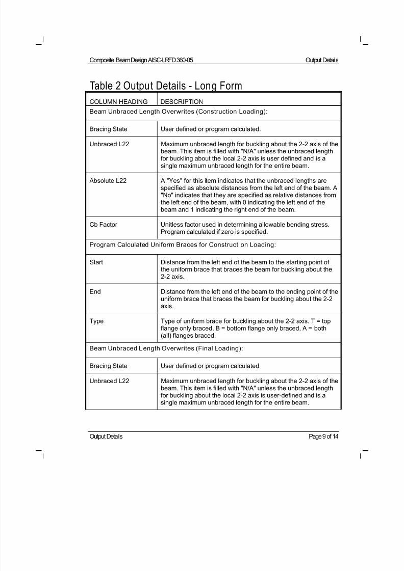
8/21/2019 Composit Beam
http://slidepdf.com/reader/full/composit-beam 156/161
Composite Beam Design AISC-LRFD 360-05 Output Details
Output Details Page 9 of 14
Table 2 Output Details - Long Form
COLUMN HEADING DESCRIPTION
Beam Unbraced Length Overwrites (Construction Loading):
Bracing State User defined or program calculated.
Unbraced L22 Maximum unbraced length for buckling about the 2-2 axis of thebeam. This item is filled with "N/A" unless the unbraced lengthfor buckling about the local 2-2 axis is user defined and is asingle maximum unbraced length for the entire beam.
Absolute L22 A "Yes" for this item indicates that the unbraced lengths arespecified as absolute distances from the left end of the beam. A"No" indicates that they are specified as relative distances fromthe left end of the beam, with 0 indicating the left end of thebeam and 1 indicating the right end of the beam.
Cb Factor Unitless factor used in determining allowable bending stress.Program calculated if zero is specified.
Program Calculated Uniform Braces for Construction Loading:
Start Distance from the left end of the beam to the starting point ofthe uniform brace that braces the beam for buckling about the2-2 axis.
End Distance from the left end of the beam to the ending point of theuniform brace that braces the beam for buckling about the 2-2axis.
Type Type of uniform brace for buckling about the 2-2 axis. T = topflange only braced, B = bottom flange only braced, A = both(all) flanges braced.
Beam Unbraced Length Overwrites (Final Loading):
Bracing State User defined or program calculated.
Unbraced L22 Maximum unbraced length for buckling about the 2-2 axis of thebeam. This item is filled with "N/A" unless the unbraced lengthfor buckling about the local 2-2 axis is user-defined and is asingle maximum unbraced length for the entire beam.
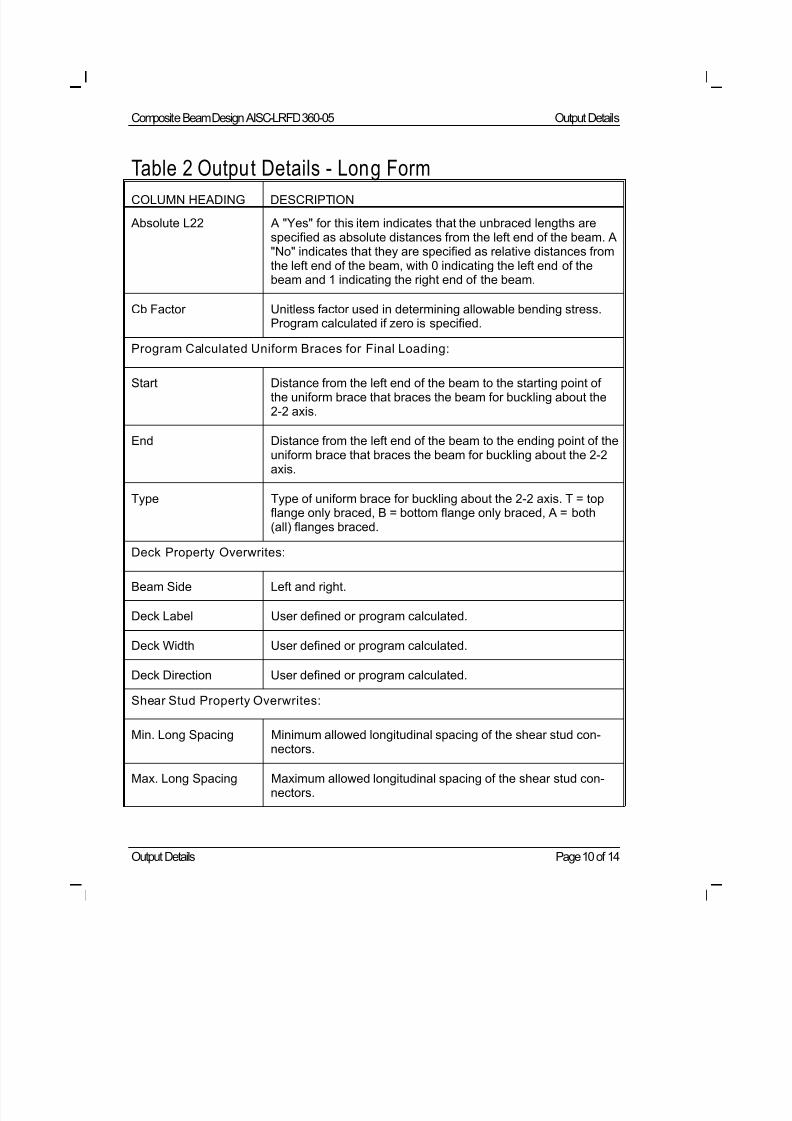
8/21/2019 Composit Beam
http://slidepdf.com/reader/full/composit-beam 157/161
Composite Beam Design AISC-LRFD 360-05 Output Details
Output Details Page 10 of 14
Table 2 Output Details - Long Form
COLUMN HEADING DESCRIPTION
Absolute L22 A "Yes" for this item indicates that the unbraced lengths arespecified as absolute distances from the left end of the beam. A"No" indicates that they are specified as relative distances fromthe left end of the beam, with 0 indicating the left end of thebeam and 1 indicating the right end of the beam.
Cb Factor Unitless factor used in determining allowable bending stress.Program calculated if zero is specified.
Program Calculated Uniform Braces for Final Loading:
Start Distance from the left end of the beam to the starting point ofthe uniform brace that braces the beam for buckling about the2-2 axis.
End Distance from the left end of the beam to the ending point of theuniform brace that braces the beam for buckling about the 2-2axis.
Type Type of uniform brace for buckling about the 2-2 axis. T = topflange only braced, B = bottom flange only braced, A = both(all) flanges braced.
Deck Property Overwrites:
Beam Side Left and right.
Deck Label User defined or program calculated.
Deck Width User defined or program calculated.
Deck Direction User defined or program calculated.
Shear Stud Property Overwrites:
Min. Long Spacing Minimum allowed longitudinal spacing of the shear stud con-
nectors.
Max. Long Spacing Maximum allowed longitudinal spacing of the shear stud con-nectors.
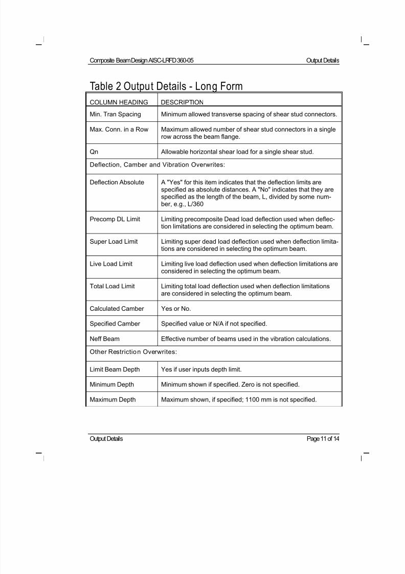
8/21/2019 Composit Beam
http://slidepdf.com/reader/full/composit-beam 158/161
Composite Beam Design AISC-LRFD 360-05 Output Details
Output Details Page 11 of 14
Table 2 Output Details - Long Form
COLUMN HEADING DESCRIPTION
Min. Tran Spacing Minimum allowed transverse spacing of shear stud connectors.
Max. Conn. in a Row Maximum allowed number of shear stud connectors in a singlerow across the beam flange.
Qn Allowable horizontal shear load for a single shear stud.
Deflection, Camber and Vibration Overwrites:
Deflection Absolute A "Yes" for this item indicates that the deflection limits are
specified as absolute distances. A "No" indicates that they arespecified as the length of the beam, L, divided by some num-ber, e.g., L/360
Precomp DL Limit Limiting precomposite Dead load deflection used when deflec-tion limitations are considered in selecting the optimum beam.
Super Load Limit Limiting super dead load deflection used when deflection limita-tions are considered in selecting the optimum beam.
Live Load Limit Limiting live load deflection used when deflection limitations areconsidered in selecting the optimum beam.
Total Load Limit Limiting total load deflection used when deflection limitationsare considered in selecting the optimum beam.
Calculated Camber Yes or No.
Specified Camber Specified value or N/A if not specified.
Neff Beam Effective number of beams used in the vibration calculations.
Other Restriction Overwrites:
Limit Beam Depth Yes if user inputs depth limit.
Minimum Depth Minimum shown if specified. Zero is not specified.
Maximum Depth Maximum shown, if specified; 1100 mm is not specified.
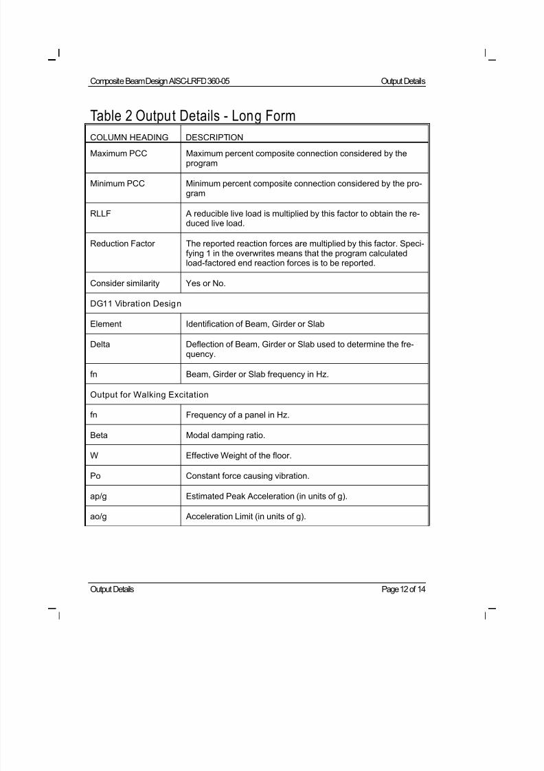
8/21/2019 Composit Beam
http://slidepdf.com/reader/full/composit-beam 159/161
Composite Beam Design AISC-LRFD 360-05 Output Details
Output Details Page 12 of 14
Table 2 Output Details - Long Form
COLUMN HEADING DESCRIPTION
Maximum PCC Maximum percent composite connection considered by theprogram
Minimum PCC Minimum percent composite connection considered by the pro-gram
RLLF A reducible live load is multiplied by this factor to obtain the re-duced live load.
Reduction Factor The reported reaction forces are multiplied by this factor. Speci-fying 1 in the overwrites means that the program calculatedload-factored end reaction forces is to be reported.
Consider similarity Yes or No.
DG11 Vibration Design
Element Identification of Beam, Girder or Slab
Delta Deflection of Beam, Girder or Slab used to determine the fre-quency.
fn Beam, Girder or Slab frequency in Hz.
Output for Walking Excitation
fn Frequency of a panel in Hz.
Beta Modal damping ratio.
W Effective Weight of the floor.
Po Constant force causing vibration.
ap/g Estimated Peak Acceleration (in units of g).
ao/g Acceleration Limit (in units of g).
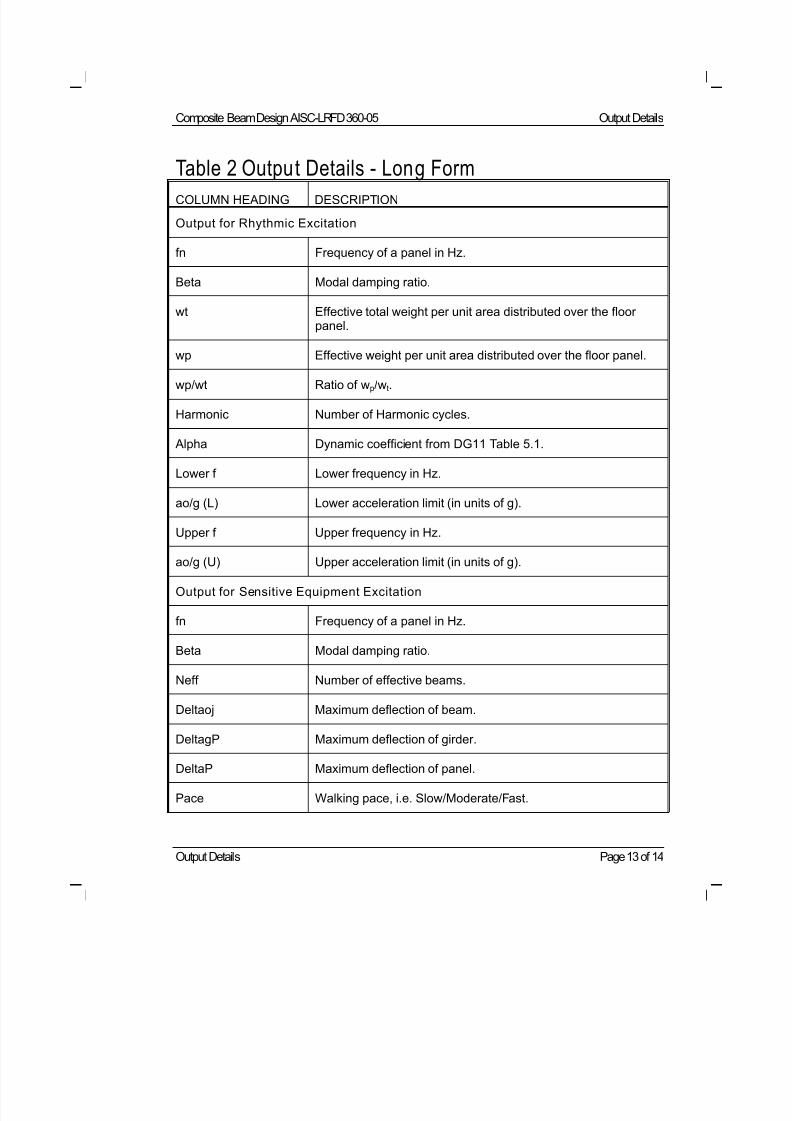
8/21/2019 Composit Beam
http://slidepdf.com/reader/full/composit-beam 160/161
Composite Beam Design AISC-LRFD 360-05 Output Details
Output Details Page 13 of 14
Table 2 Output Details - Long Form
COLUMN HEADING DESCRIPTION
Output for Rhythmic Excitation
fn Frequency of a panel in Hz.
Beta Modal damping ratio.
wt Effective total weight per unit area distributed over the floorpanel.
wp Effective weight per unit area distributed over the floor panel.
wp/wt Ratio of wp/wt.
Harmonic Number of Harmonic cycles.
Alpha Dynamic coefficient from DG11 Table 5.1.
Lower f Lower frequency in Hz.
ao/g (L) Lower acceleration limit (in units of g).
Upper f Upper frequency in Hz.
ao/g (U) Upper acceleration limit (in units of g).
Output for Sensitive Equipment Excitation
fn Frequency of a panel in Hz.
Beta Modal damping ratio.
Neff Number of effective beams.
Deltaoj Maximum deflection of beam.
DeltagP Maximum deflection of girder.
DeltaP Maximum deflection of panel.
Pace Walking pace, i.e. Slow/Moderate/Fast.
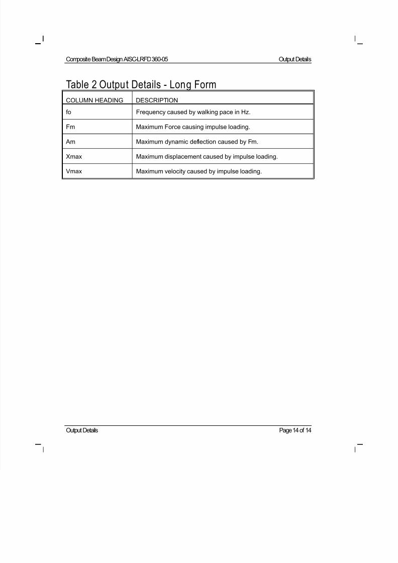
8/21/2019 Composit Beam
http://slidepdf.com/reader/full/composit-beam 161/161
Composite Beam Design AISC-LRFD 360-05 Output Details
Table 2 Output Details - Long Form
COLUMN HEADING DESCRIPTION
fo Frequency caused by walking pace in Hz.
Fm Maximum Force causing impulse loading.
Am Maximum dynamic deflection caused by Fm.
Xmax Maximum displacement caused by impulse loading.
Vmax Maximum velocity caused by impulse loading.