Embed Size (px)
Citation preview
COMPOSITES FACT SHEET
Composites Fact sheet
1
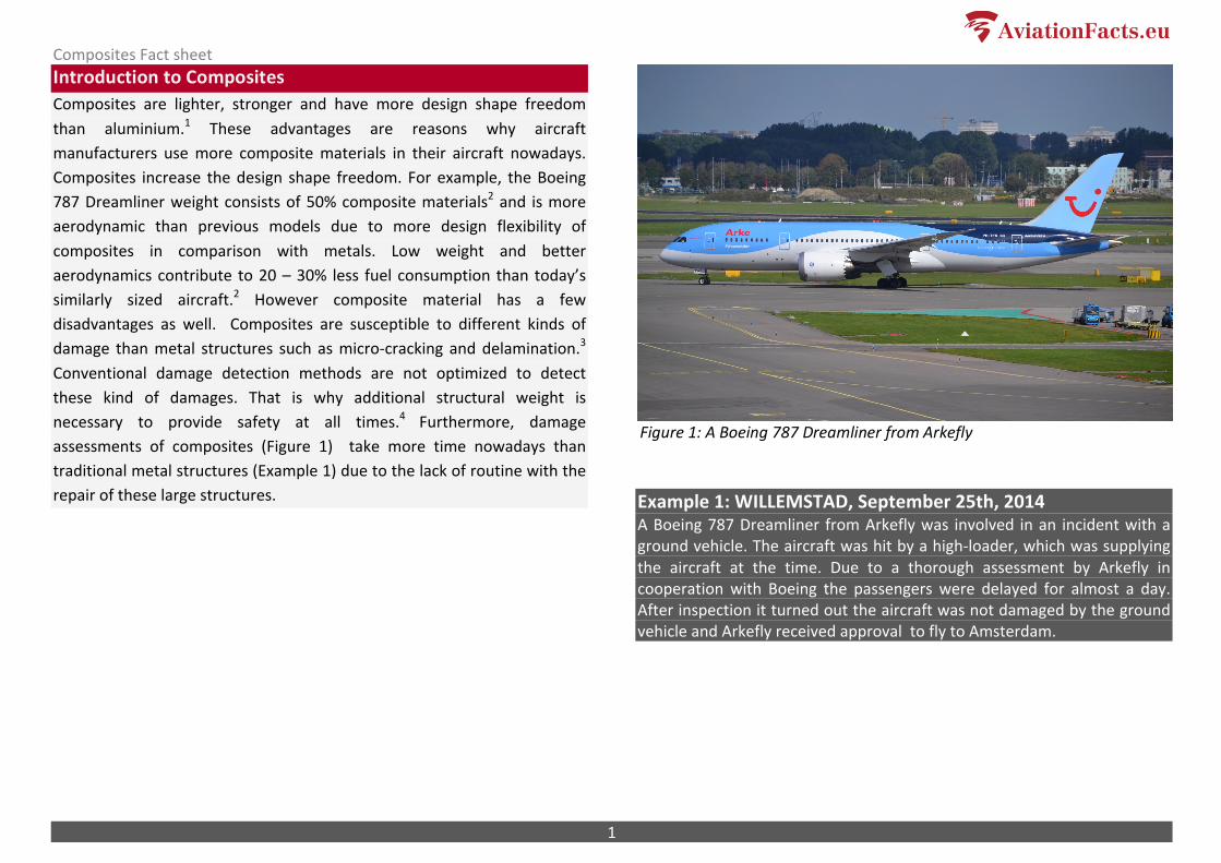
Introduction to Composites Composites are lighter, stronger and have more design shape freedom than aluminium.1 These advantages are reasons why aircraft manufacturers use more composite materials in their aircraft nowadays. Composites increase the design shape freedom. For example, the Boeing 787 Dreamliner weight consists of 50% composite materials2 and is more aerodynamic than previous models due to more design flexibility of composites in comparison with metals. Low weight and better aerodynamics contribute to 20 – 30% less fuel consumption than today’s similarly sized aircraft.2 However composite material has a few disadvantages as well. Composites are susceptible to different kinds of damage than metal structures such as micro-‐cracking and delamination.3 Conventional damage detection methods are not optimized to detect these kind of damages. That is why additional structural weight is necessary to provide safety at all times.4 Furthermore, damage assessments of composites (Figure 1) take more time nowadays than traditional metal structures (Example 1) due to the lack of routine with the repair of these large structures.
Example 1: WILLEMSTAD, September 25th, 2014 A Boeing 787 Dreamliner from Arkefly was involved in an incident with a ground vehicle. The aircraft was hit by a high-‐loader, which was supplying the aircraft at the time. Due to a thorough assessment by Arkefly in cooperation with Boeing the passengers were delayed for almost a day. After inspection it turned out the aircraft was not damaged by the ground vehicle and Arkefly received approval to fly to Amsterdam.
Figure 1: A Boeing 787 Dreamliner from Arkefly
Composites Fact sheet
2
Properties of composites A composite material can be described as a combination of two or more materials having a recognizable interface between them.5 In this fact sheet the focus will be on the fibre-‐reinforced composites used in the aviation industry. This is a combination of fibres and a matrix (polymer resin). The two materials work together to combine the individual properties, which results in a lighter or stronger structure in comparison with traditional metal structures. It is possible to create a large part of an aircraft out of one piece composite. (Figure 2)
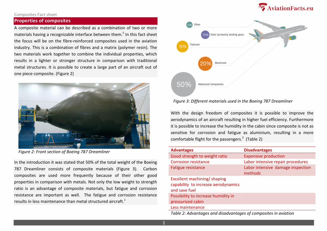
Figure 2: Front section of Boeing 787 Dreamliner
In the introduction it was stated that 50% of the total weight of the Boeing 787 Dreamliner consists of composite materials (Figure 3). Carbon composites are used more frequently because of their other good properties in comparison with metals. Not only the low weight to strength ratio is an advantage of composite materials, but fatigue and corrosion resistance are important as well. The fatigue and corrosion resistance results in less maintenance than metal structured aircraft.1
With the design freedom of composites it is possible to improve the aerodynamics of an aircraft resulting in higher fuel efficiency. Furthermore it is possible to increase the humidity in the cabin since composite is not as sensitive for corrosion and fatigue as aluminium, resulting in a more comfortable flight for the passengers.2 (Table 2)
Advantages Disadvantages Good strength to weight ratio Expensive production Corrosion resistance Labor intensive repair procedures Fatigue resistance Labor intensive damage inspection
methods Excellent machining/ shaping capability to increase aerodynamics and save fuel
Possibility to increase humidity in pressurized cabin
Less maintenance Table 2: Advantages and disadvantages of composites in aviation
Figure 3: Different materials used in the Boeing 787 Dreamliner
Composites Fact sheet
3
Different sources of damage Nowadays the production of composites is rather expensive in comparison with metals. However, mass production will probably decrease the price in the future. The biggest disadvantage at the moment is the labor intensive damage inspection methods. This can be damage from foreign objects or imperfections in the composite material. Damage of composite materials is different than damage in metals such as aluminium. After an analysis of the types sources of these damages, the different kinds of inspection methods will be described. If the damage sources are not clear it can result in unknown damaged parts and, in a worst case scenario, can lead to a total failure of the aircraft structure. The most frequent sources can be divided into the following categories: impact in-‐flight, foreign object damage (FOD) and damage caused by ground handling equipment. 6
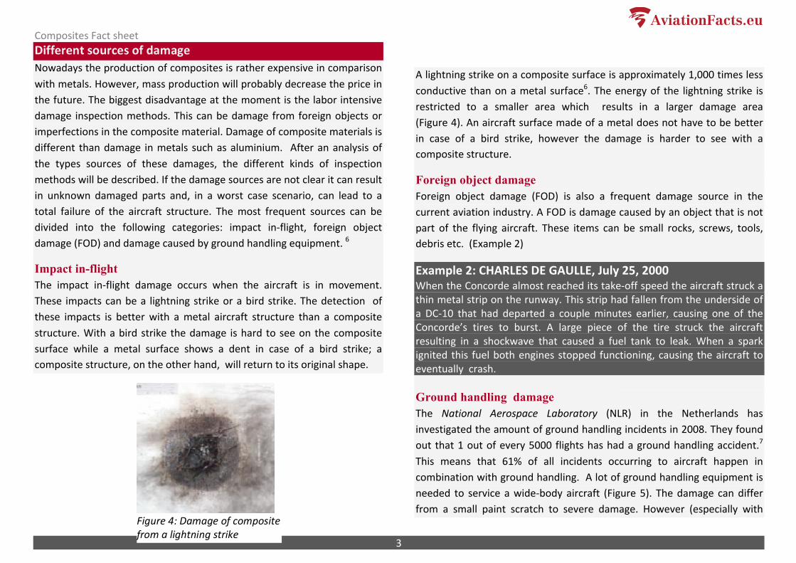
Impact in-flight The impact in-‐flight damage occurs when the aircraft is in movement. These impacts can be a lightning strike or a bird strike. The detection of these impacts is better with a metal aircraft structure than a composite structure. With a bird strike the damage is hard to see on the composite surface while a metal surface shows a dent in case of a bird strike; a composite structure, on the other hand, will return to its original shape.
A lightning strike on a composite surface is approximately 1,000 times less conductive than on a metal surface6. The energy of the lightning strike is restricted to a smaller area which results in a larger damage area (Figure 4). An aircraft surface made of a metal does not have to be better in case of a bird strike, however the damage is harder to see with a composite structure.
Foreign object damage Foreign object damage (FOD) is also a frequent damage source in the current aviation industry. A FOD is damage caused by an object that is not part of the flying aircraft. These items can be small rocks, screws, tools, debris etc. (Example 2)
Example 2: CHARLES DE GAULLE, July 25, 2000 When the Concorde almost reached its take-‐off speed the aircraft struck a thin metal strip on the runway. This strip had fallen from the underside of a DC-‐10 that had departed a couple minutes earlier, causing one of the Concorde’s tires to burst. A large piece of the tire struck the aircraft resulting in a shockwave that caused a fuel tank to leak. When a spark ignited this fuel both engines stopped functioning, causing the aircraft to eventually crash.
Ground handling damage The National Aerospace Laboratory (NLR) in the Netherlands has investigated the amount of ground handling incidents in 2008. They found out that 1 out of every 5000 flights has had a ground handling accident.7 This means that 61% of all incidents occurring to aircraft happen in combination with ground handling. A lot of ground handling equipment is needed to service a wide-‐body aircraft (Figure 5). The damage can differ from a small paint scratch to severe damage. However (especially with
Figure 4: Damage of composite from a lightning strike
Composites Fact sheet
4
composite materials) it is sometimes not visible on the outside how severe the damage is on the inside. This makes it very important that an incident is always reported.
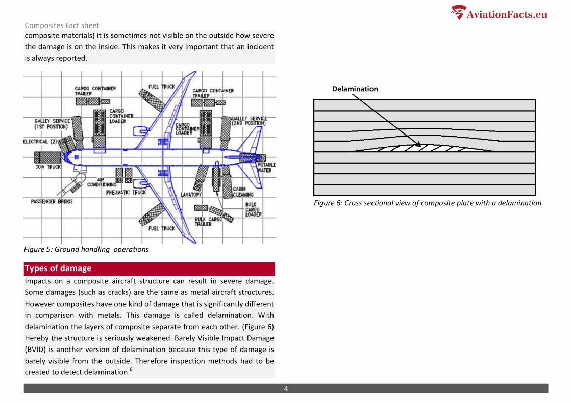
Types of damage Impacts on a composite aircraft structure can result in severe damage. Some damages (such as cracks) are the same as metal aircraft structures. However composites have one kind of damage that is significantly different in comparison with metals. This damage is called delamination. With delamination the layers of composite separate from each other. (Figure 6) Hereby the structure is seriously weakened. Barely Visible Impact Damage (BVID) is another version of delamination because this type of damage is barely visible from the outside. Therefore inspection methods had to be created to detect delamination.8
Delamination
Figure 5: Ground handling operations
Figure 6: Cross sectional view of composite plate with a delamination
Composites Fact sheet
5
Damage detection methods A visual inspection is often used as a damage detection method. However, to detect impact damage that is barely visible to the human eye other detection methods have been developed. The following three non-‐destructive inspection (NDI) methods are portable and practical in use in the aviation industry: visual inspection, ultrasonic pulse echo inspection and a tap test inspection. For a more thorough investigation, radiography, thermography and shearography are used. A relative new NDI technique currently under development is ultrasonic verification (USV).
Visual inspection A visual inspection is used first when inspecting the surface of an aircraft. With a visual inspection it is possible to detect paint scratches and wrinkles. Also discoloration can be detected. Discoloration can be caused due to a lightning strike. For internal damage of a composite material more sophisticated NDI techniques are needed.
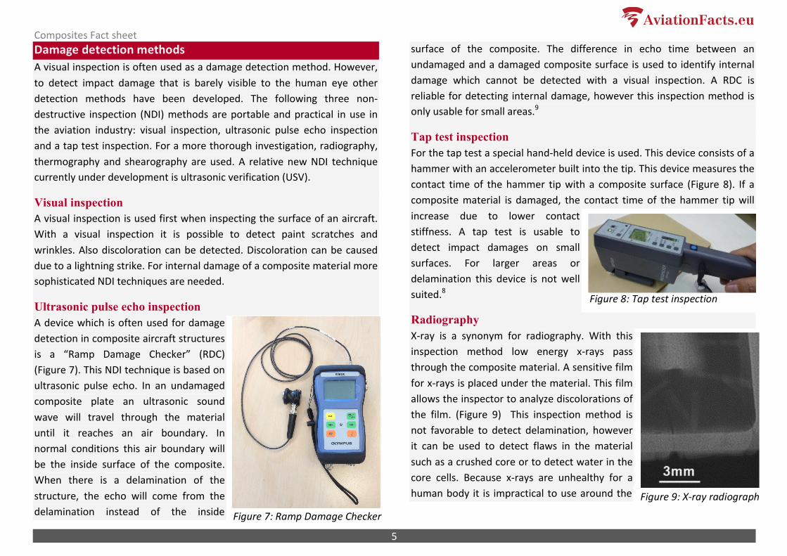
Ultrasonic pulse echo inspection A device which is often used for damage detection in composite aircraft structures is a “Ramp Damage Checker” (RDC) (Figure 7). This NDI technique is based on ultrasonic pulse echo. In an undamaged composite plate an ultrasonic sound wave will travel through the material until it reaches an air boundary. In normal conditions this air boundary will be the inside surface of the composite. When there is a delamination of the structure, the echo will come from the delamination instead of the inside
surface of the composite. The difference in echo time between an undamaged and a damaged composite surface is used to identify internal damage which cannot be detected with a visual inspection. A RDC is reliable for detecting internal damage, however this inspection method is only usable for small areas.9
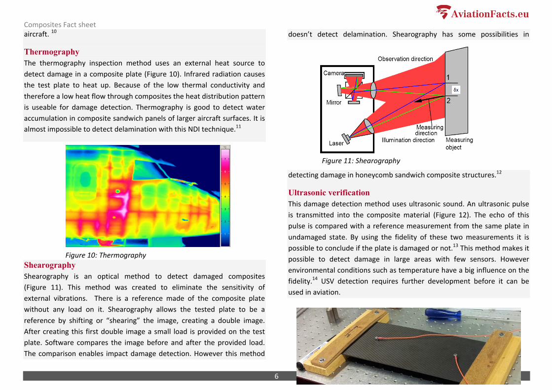
Tap test inspection For the tap test a special hand-‐held device is used. This device consists of a hammer with an accelerometer built into the tip. This device measures the contact time of the hammer tip with a composite surface (Figure 8). If a composite material is damaged, the contact time of the hammer tip will increase due to lower contact stiffness. A tap test is usable to detect impact damages on small surfaces. For larger areas or delamination this device is not well suited.8
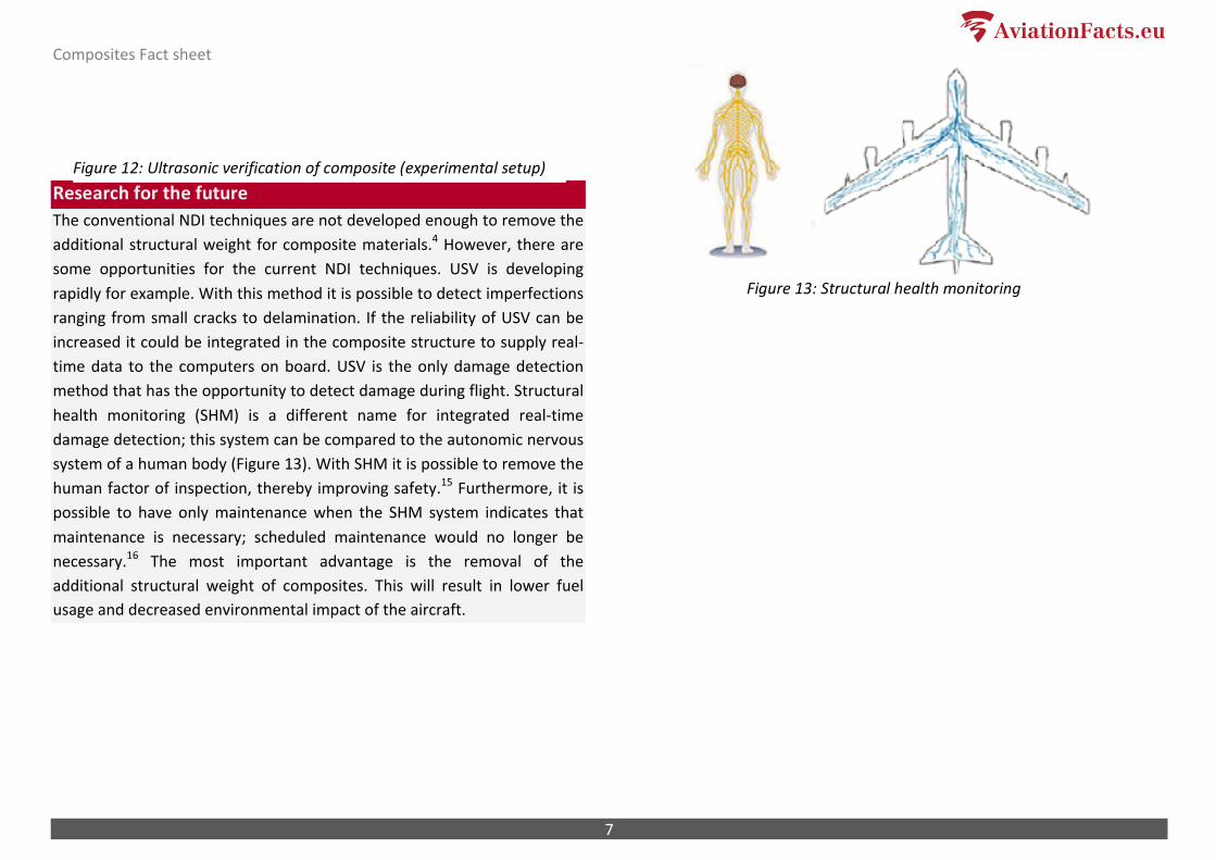
Radiography X-‐ray is a synonym for radiography. With this inspection method low energy x-‐rays pass through the composite material. A sensitive film for x-‐rays is placed under the material. This film allows the inspector to analyze discolorations of the film. (Figure 9) This inspection method is not favorable to detect delamination, however it can be used to detect flaws in the material such as a crushed core or to detect water in the core cells. Because x-‐rays are unhealthy for a human body it is impractical to use around the
Figure 8: Tap test inspection
Figure 7: Ramp Damage Checker Figure 9: X-‐ray radiograph
Composites Fact sheet
6
aircraft. 10
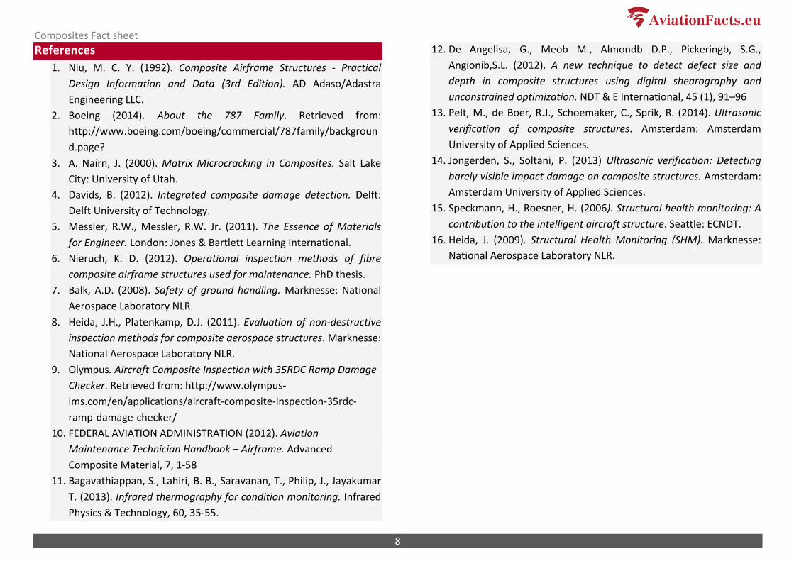
Thermography The thermography inspection method uses an external heat source to detect damage in a composite plate (Figure 10). Infrared radiation causes the test plate to heat up. Because of the low thermal conductivity and therefore a low heat flow through composites the heat distribution pattern is useable for damage detection. Thermography is good to detect water accumulation in composite sandwich panels of larger aircraft surfaces. It is almost impossible to detect delamination with this NDI technique.11
Shearography Shearography is an optical method to detect damaged composites (Figure 11). This method was created to eliminate the sensitivity of external vibrations. There is a reference made of the composite plate without any load on it. Shearography allows the tested plate to be a reference by shifting or “shearing” the image, creating a double image. After creating this first double image a small load is provided on the test plate. Software compares the image before and after the provided load. The comparison enables impact damage detection. However this method
doesn’t detect delamination. Shearography has some possibilities in
detecting damage in honeycomb sandwich composite structures.12
Ultrasonic verification This damage detection method uses ultrasonic sound. An ultrasonic pulse is transmitted into the composite material (Figure 12). The echo of this pulse is compared with a reference measurement from the same plate in undamaged state. By using the fidelity of these two measurements it is possible to conclude if the plate is damaged or not.13 This method makes it possible to detect damage in large areas with few sensors. However environmental conditions such as temperature have a big influence on the fidelity.14 USV detection requires further development before it can be used in aviation.
Figure 10: Thermography
Figure 11: Shearography
Composites Fact sheet
7
Research for the future The conventional NDI techniques are not developed enough to remove the additional structural weight for composite materials.4 However, there are some opportunities for the current NDI techniques. USV is developing rapidly for example. With this method it is possible to detect imperfections ranging from small cracks to delamination. If the reliability of USV can be increased it could be integrated in the composite structure to supply real-‐time data to the computers on board. USV is the only damage detection method that has the opportunity to detect damage during flight. Structural health monitoring (SHM) is a different name for integrated real-‐time damage detection; this system can be compared to the autonomic nervous system of a human body (Figure 13). With SHM it is possible to remove the human factor of inspection, thereby improving safety.15 Furthermore, it is possible to have only maintenance when the SHM system indicates that maintenance is necessary; scheduled maintenance would no longer be necessary.16 The most important advantage is the removal of the additional structural weight of composites. This will result in lower fuel usage and decreased environmental impact of the aircraft.
Figure 12: Ultrasonic verification of composite (experimental setup)
Figure 13: Structural health monitoring
Composites Fact sheet
8
References 1. Niu, M. C. Y. (1992). Composite Airframe Structures -‐ Practical
Design Information and Data (3rd Edition). AD Adaso/Adastra Engineering LLC.
2. Boeing (2014). About the 787 Family. Retrieved from: http://www.boeing.com/boeing/commercial/787family/background.page?
3. A. Nairn, J. (2000). Matrix Microcracking in Composites. Salt Lake City: University of Utah.
4. Davids, B. (2012). Integrated composite damage detection. Delft: Delft University of Technology.
5. Messler, R.W., Messler, R.W. Jr. (2011). The Essence of Materials for Engineer. London: Jones & Bartlett Learning International.
6. Nieruch, K. D. (2012). Operational inspection methods of fibre composite airframe structures used for maintenance. PhD thesis.
7. Balk, A.D. (2008). Safety of ground handling. Marknesse: National Aerospace Laboratory NLR.
8. Heida, J.H., Platenkamp, D.J. (2011). Evaluation of non-‐destructive inspection methods for composite aerospace structures. Marknesse: National Aerospace Laboratory NLR.
9. Olympus. Aircraft Composite Inspection with 35RDC Ramp Damage Checker. Retrieved from: http://www.olympus-‐ims.com/en/applications/aircraft-‐composite-‐inspection-‐35rdc-‐ramp-‐damage-‐checker/
10. FEDERAL AVIATION ADMINISTRATION (2012). Aviation Maintenance Technician Handbook – Airframe. Advanced Composite Material, 7, 1-‐58
11. Bagavathiappan, S., Lahiri, B. B., Saravanan, T., Philip, J., Jayakumar T. (2013). Infrared thermography for condition monitoring. Infrared Physics & Technology, 60, 35-‐55.
12. De Angelisa, G., Meob M., Almondb D.P., Pickeringb, S.G., Angionib,S.L. (2012). A new technique to detect defect size and depth in composite structures using digital shearography and unconstrained optimization. NDT & E International, 45 (1), 91–96
13. Pelt, M., de Boer, R.J., Schoemaker, C., Sprik, R. (2014). Ultrasonic verification of composite structures. Amsterdam: Amsterdam University of Applied Sciences.
14. Jongerden, S., Soltani, P. (2013) Ultrasonic verification: Detecting barely visible impact damage on composite structures. Amsterdam: Amsterdam University of Applied Sciences.
15. Speckmann, H., Roesner, H. (2006). Structural health monitoring: A contribution to the intelligent aircraft structure. Seattle: ECNDT.
16. Heida, J. (2009). Structural Health Monitoring (SHM). Marknesse: National Aerospace Laboratory NLR.
Composites Fact sheet
9
Dutch summary Composieten zijn lichter, sterker en geven meer vrijheid in het ontwerp van het vliegtuig dan aluminium.1 Dit zijn een aantal primaire redenen dat vliegtuigfabrikanten meer composieten in vliegtuigen gaan gebruiken. Het gewicht van de Boeing 787 Dreamliner bestaat bijvoorbeeld voor 50 procent uit composieten, wat bijdraagt aan 20-‐30% brandstofbesparing door een lager gewicht en betere aerodynamica van het vliegtuig in vergelijking met even grote vliegtuigen gemaakt van voornamelijk aluminium.2
Composieten hebben echter vergeleken met metalen andere soorten schade, zoals kleine barstjes en delaminatie.3 Hedendaagse methodes om schade bij composieten te vinden zijn niet adequaat om kleine barstjes en delaminatie te detecteren. Daarom is het nodig om extra structureel gewicht aan onderdelen van composiet toe te voegen om de veiligheid ten alle tijden te waarborgen.4 Om dit extra gewicht te elimineren is het nodig om een adequate methode te hebben om schade te detecteren bij composieten. Een lichter vliegtuig zal resulteren in minder brandstofverbruik, waarbij de impact op het milieu wordt verminderd.
De detectiemethoden van schade in composieten worden op dit moment snel ontwikkeld. “Ultrasonic Verification” (USV) is bijvoorbeeld een methode waarmee schade wordt gedetecteerd met behulp van ultrasone geluidsgolven. Als de betrouwbaarheid van deze methode kan worden verhoogd, is het mogelijk om dit te integreren in het vliegtuig. Zo kan tijdens het vliegen data naar de computers aan boord worden verzonden. Dit wordt ook wel “Structural Health Monitoring” (SHM) genoemd. Met SHM is het mogelijk om de menselijke factor van het schade detecteren te elimineren wat zal zorgen voor meer veiligheid.15
Image references 1 https://www.flickr.com/photos/awilson154/15278513859/in/photolist-‐ 2 Nieruch, K. D. (2012). Operational inspection methods of fibre composite
airframe structures used for maintenance. PhD thesis. Page 28 3 Hale, J. (2008). Boeing 787 from the ground up. Aeromagazine, 04 (06). 4 Nieruch, K. D. (2012). Operational inspection methods of fibre composite
airframe structures used for maintenance. PhD thesis. Page 39 5 Nieruch, K. D. (2012). Operational inspection methods of fibre composite
airframe structures used for maintenance. PhD thesis. Page 42 6 Ee, S. (2014). Schematic view of a delamination in composite. Created by the
author 7 Ee, S. (2014). Ramp Damage Checker. Photographed by the author 8 http://www.jrtech.co.uk/web/images/stories/QA/wp632amxy300x159.jpg 9 Thornton, J. (2004). Enhanced radiography for aircraft materials and
components. Engineering Failure Analysis, 11(2), 207-‐220. 10 http://www.infratec.eu/uploads/tx_templavoila/Thermography-‐Aerospace-‐
Industry-‐Insulation-‐failure.gif 11 http://opticalengineering.spiedigitallibrary.org/data/Journals/OPTICE/
926773/OE_52_10_101902_f001.png 12 Pelt, M., de Boer, R.J., Schoemaker, C., Sprik, R. (2014). Ultrasonic
verification of composite structures. Amsterdam: Amsterdam University of Applied Sciences. Page 3
13 Heida, J. (2009). Structural Health Monitoring (SHM). Marknesse: National
Aerospace Laboratory NLR. Page 7
Composites Fact sheet
10
This is a Luchtvaartfeiten.nl / AviationFacts.eu publication. Author: Sam van Ee Editorial staff: R.J. de Boer PhD Msc, G. Boosten MSc & G.J.S. Vlaming MSc Copying texts is allowed. Please cite: ‘Luchtvaartfeiten.nl (2015), Composites Fact sheet, www.luchtvaartfeiten.nl’ Luchtvaartfeiten.nl is an initiative by the Aviation Academy at the Amsterdam University of Applied Sciences (HvA). Students and teachers share knowledge with politicians and the general public to ensure discussions are based on facts. December 2014 Revised February 2015


![Active Thermography – NDT Method for Structural · PDF fileActive Thermography ... Nondestructive Testing Handbook, Vol. 3 Infrared and Thermal Testing] Pulse-phase-thermography](https://img.pdfslide.tips/doc/110x75/5a78d7ef7f8b9a21538e2b68/active-thermography-ndt-method-for-structural-active-thermography-.jpg)