Embed Size (px)
Citation preview
COMPUMOITOR
F-SERIE:S
MOTOR/DRIVER
OPERATOR'S Mj~NUAL
P IN a a-()05 '7 2 8:-0 1
COMPUMOTOR CORPORATiON
5500 BUSINESS PARK DRiVE
ROHNERT PAF?K CA 94928
! 1
T 1 "
COMPUMOTOR F-SERIES MOTOR/DRIVER SYSTEMS INSTALLATION I~ OPERATION MANUAL
INDEX Page
I. Introd.uction ........... II " ...... " ....................... II"" ........... ... 2
II. Inspection •••••••••••••••••••••••••••••••••••••• 2
III.. Unpac.k! ng ................... • ' ~Ih ., .... " ............................................. 2
IV. Motmtlng ...................... n •••••••••••••••••• 3
V. Connecting AC Power ........... n •••••••••••••••••• 4
VI. Checkout ....••...••....... 1. " •••••••••••••••••• •• 4
A. Proper Torque B. Pulse Source Connection C. Pulse Generation D. Compumotor Pulse Generation
VII. Limi ted Travel Mechanisms ........................ 6
VIII. Dynamic CharacteristIcs of <II Compumotor ••••••••• 7
IX. Periodic Maintenance •••••••••••••••••• , •••••••••• 7
x. Troubleshooting ••••••••••••••••••••••••••••••••• 8
XI. Factory Service ...... , It 'I ••• 1 •••••••••• "'1' •••••••• 9
XII • Further Notes .......... I, .... II ........................................... 9
XIII. Specifications ................. ' ..... ' ........ ' ................... ........... 10
Appendix A: Case Temp. RiS!!! "ITS. RMS Velocity ••• 12
Appendix B: Speed Torque Curve!I •••••••••••••••• 13
Appendix C: Wiring Diagram - Driver to Indexer •••••••••••••••••••••••••••• 15
Appendix D: Warranty ••••••••••••••••••••••••••• 16
CopyrIght 1986 by Canpumotor IC,orp'Clrattion Specifications Subject to Challge ,~rIthout Notice
pIN 88-005728-01
COMPUMOTOR F-SERIJ:!:S MOTOR/DRIVER SYSTEMS
INSTALLATION ANI) O:P'ERATION MANUAL
I. INTRODUCTION:
WARNING!
Compumotor Corporation has made a. spe'd;'!l effort In the design and construction ()f its products to IJl;Ilke the.m both versatile and easy to use. The mechanical torque produced by these motor/drivers is capable of damaging or' destroying the equipment tCI which they are connected if improperly installed, operated or senri,ced. Only persons qualified in servicing and installing hazardous voltage electrical and limited-travel mechanical systems should attempt thls procedure.
The F-Series motor/driver is a high pcn<ler tDicrostepping drive wi th a low pass filter added to reduce the 20KHZ switching noise in the ouput current which cannot be tolerated by the low inductance of F-series motors.
The F57-83 is a standard hybrid st:eppl~r motor. The F83-49 series motor dri ver is a disk rotor synchro-st4!lP m4Jtor. The disk rotor causes the motor to have an extremely low ro1:()r llnert:la making it ideal for applications requiring high accelerat:Lo·ns.
II. INSPECTION
Carefully inspect the shipping cart:on(s) fClr any evidence of physical abuse or damage and note any findings 4Jn the Waybill at the time of receipt. In cases of severe damage, It Is r'ecommended that the shipment be rejected entirely. Ccmpumotor C.:)rpo'r'ation cannot be responsible for in-transit damage.
III. UNPACKING
Use care in opening the shipping c~n·ton( s) no that the cables supplied are not cut or damaged. Verify the It'ecei ptof the following Items:
Q!z
1
1
1
1
1
DeSCription
Compumotor with 1.0 [,oot (3M) Drive Cable
Driver (Power kIIlpl1f:1er-/1rranslator) Module
3-w1re AC Line Cord Ei feE!t (2M) with Ground Pin
Pulse Source Cable Kh
Standard Product LIne! Brochure
-2--
r 1
Compumotor F-Series Motor/Driver Syst.ems Installation & Operation Manual
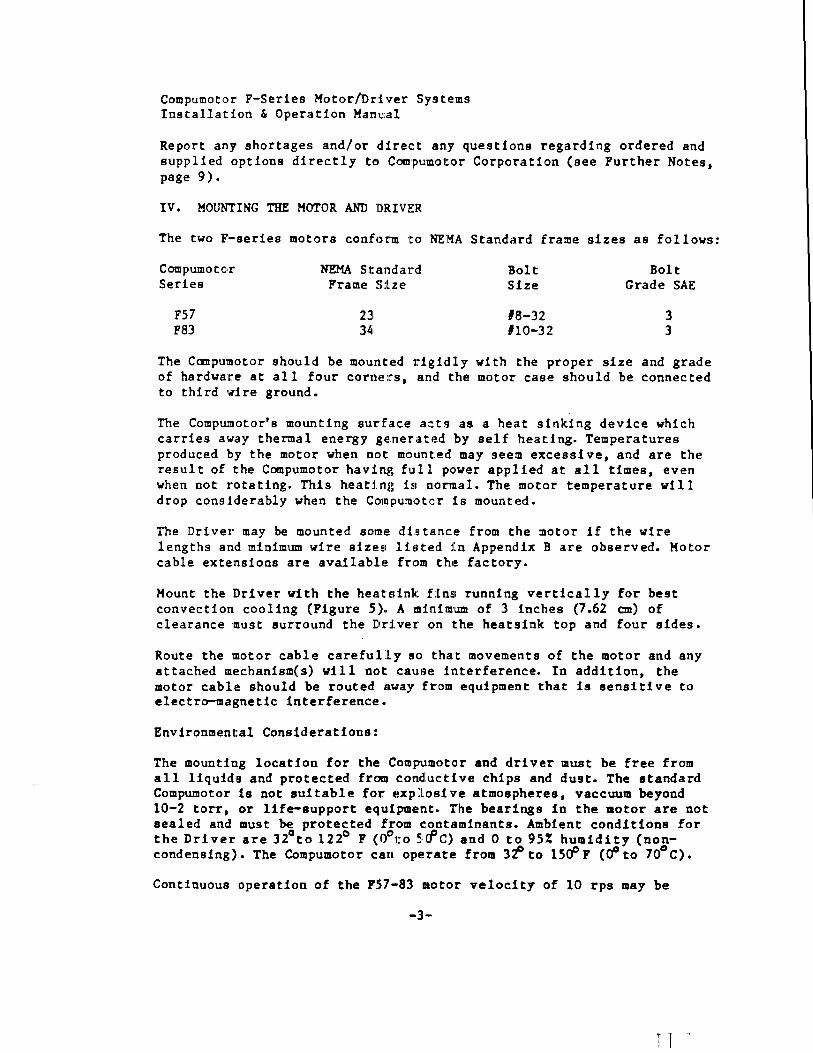
Report any shortages and/or direct any questions regarding ordered and supplied options directly t~, COII\PUlillOl:or Corporation (see Further Notes, page 9).
IV. MOUNTING THE MOTOR AND DRInR
The two F'-series motors confc>:r:ll1 Ito NE:M:A Standard frame sizes as follows:
COIIIpwnota.r Series
FS7 F83
NEMA Sl:lll1dard Frame Slze
231 34
Bolt Size
18-32 #10-32
Bolt Grade SAE
3 3
The Canpulllotor should be mounted rigidly wi th the proper size and grade of hardware at all four corners, and the motor case should be connected to third wire ground.
The Compwnotor's mounting surface a::ts as a heat sinking device which carries away thermal energy ge-nerated by self heating. Temperatures produced by the motor when not mounted may seem excessive, and are the result of the COIIIpumotor having full pe:>wer applied at all times. even when not rotating. This heatirlg h nonllal. The motor temperature will drop consIderably when the COIDpumoto>r is mounted.
The Driver may be mounted some dhtance from the motor if the wire lengths and minimum wire sizesl li~'ted lln Appendix B are observed. Motor cable extensions are ava1lablE~ fr()m the! factory.
Hount the Driver with the heat:dnk Hnsl running vertically for best convection cooling (Figure 5) .. A tllinim1W11 of 3 inches (7.62 em) of clearance must surround the Driver on the heatsink top and four sides.
Route the motor cable carefully se:> that movements of the motor and any attached mechanism(s) will not cause interference. In addition, the motor cable should be routed nway fr,om equipment that is sensi ti ve to electro-magnetic interference.
Environmental Considerations:
The mounting location for the Compum()to-r and driver must be free from all liquid.s and protected from con,dluc:tive chips and dust. The standard Compumotor is not suitable for explosive atmospheres. vaccuum beyond 10-2 torr, or life-support equipment. The bearings in the 1Iotor are not sealed and must be protected fr-om ,~:ontaminants. Ambient conditions for
a 0 c, ..D the Driver are 32 to 122 F (0 t.o 5~u G) and 0 to 95% humidity (non-condensing). The Compumotor can operate from 3i'to l5<f 1 (00 to 70° C) •
Continuous operation of the 157-83 motor velocity of 10 rps may be
-3·-
Compumotor F-Series Kotor/Driver Systems Installation & Operation Manual
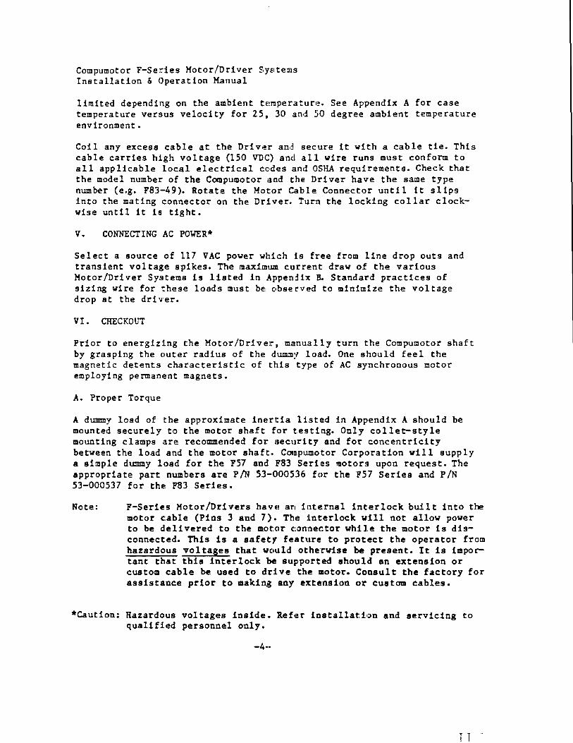
limited depending on the ambient temperature. See Appendix A for case temperature versus velocity for 25, 30 and 50 degree ambient temperature environment.
Coil any excess cable at the Driver and secure it with a cable tie. This cable carries high voltage (150 VUe:) and alII wire runs must conform to all applicable local electrical c:o,dies ,lncl OSHA requirements. Check that the model number of the COQIpumotor ,uld Ithe Dri ver have the same type number (e.g. F83-49). Rotate the Kotor Cable Connec.t()r until it slips into the mating connector on the Drl',er. Tunl the locking collar clockwise until it is tight.
V. CONNECTING AC POWER*
Select a source of 117 VAC power which Is free from line drop outs and transient voltage spikes. The maximum current draw of the various Motor/Driver Systems is listed in Appendl.:( U. Standard practices of sizing wire for these loads must be! c,bse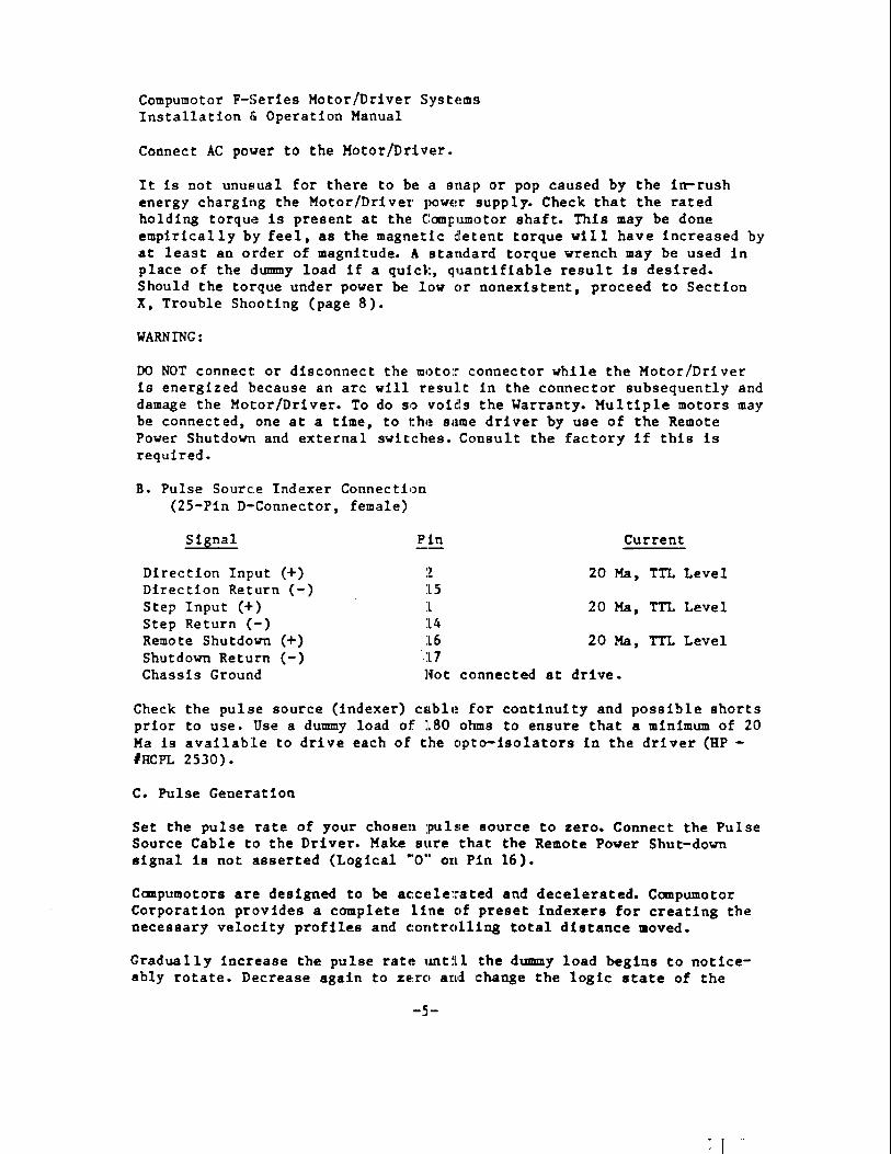
Compumotor F-Series Motor/Driver Systems Installation (, Operation Manual
Connect AC power to the Motor/Driver.
It is not unusual for there to be a snal> o,r pop caused by the in-rush energy charging the Motor/Driver l)QwE!r supply. Check that the rated holding torque is present at the Compuml)tClr shaft. This may be done empirically by feel, as the magnetic detent torque will have increased by at least an order of magnitude. A standard torque wrench may be used in place of the dummy load if a quic:k, qualltlfiable resul t is desired. Should the torque under power be low (Ir nonexistent, proceed to Section X, Trouble Shooting (page 8).
WARNING:
00 NOT connect or disconnect the tDI)tolr COO1lector while the Motor/Driver is energized because an arc will result in the connector subsequently and damage the Motor/Driver. To do so voids the Warranty. Multiple motors may be connected, one at a time, to the same driver by use of the Remote Power Shutdown and external switches. Consult the factory if this is required.
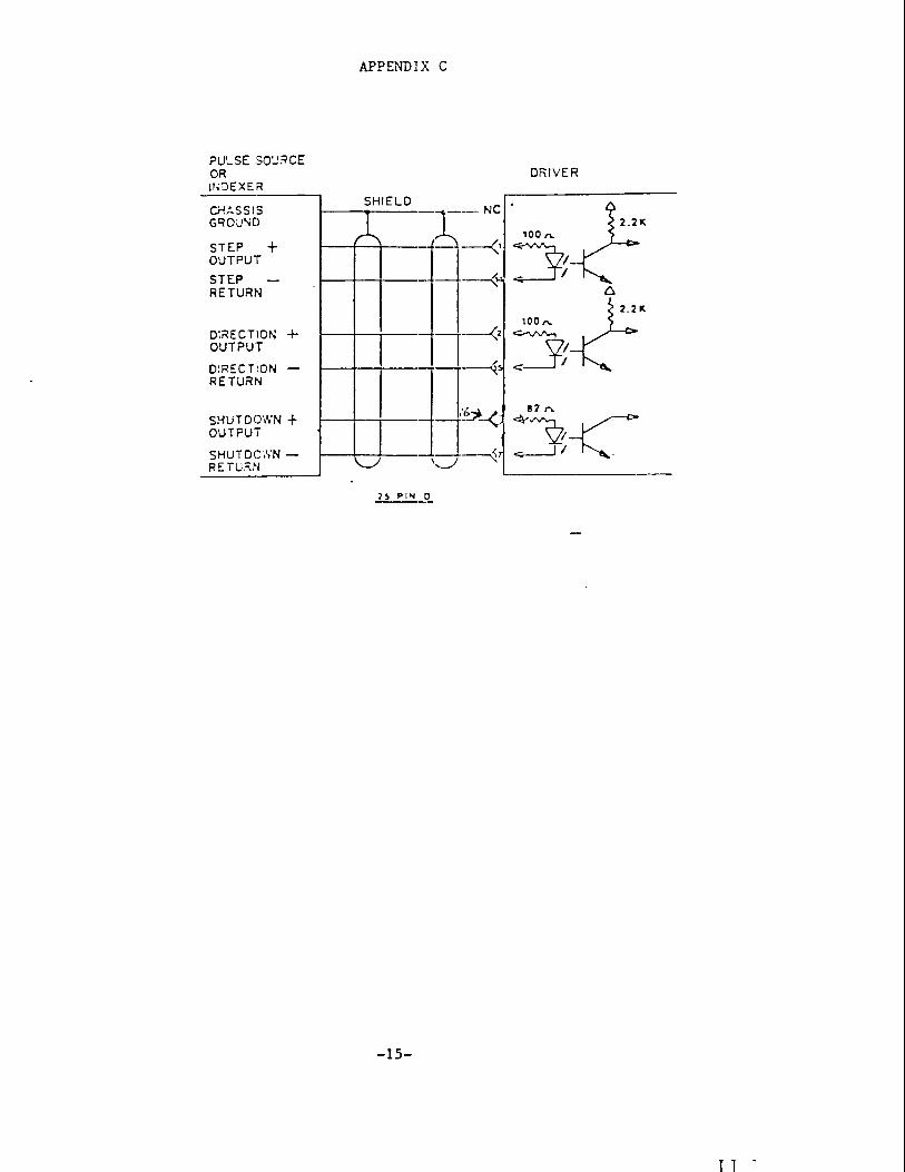
B. Pulse Source Indexer Connection (25-Pin D-Connector, female)
Si~nal l?in
Direction Input (+) :Z Direction Return (-) 15 Step Input (+) 1 Step Return (-) 14 Remote Shutdown (+) 16 Shutdown Return (-) 17 Chassis Ground J~ot
Current
20 Ma, TTL Level
20 Ma, TTL Level
20 Ma, TTL Level
conn,ected at drive.
Check the pulse source (indexer) c:ablt! for continuity and possible shorts prior to use. Use a dummy load of 180 ohms to ensure that a minimum of 20 Ma is available to drive each of the opto-isolators in the driver (HP -'HCPL 2530).
C. Pulse Generation
Set the pulse rate of your chosen ]pulse source to zero. Connect the Pulse Source Cable to the Driver. Make ElUre that the Remote Power Shut-down signal is not asserted (Logical "(Ie. Otl Pin 16).
Ccmpumotors are designed to be ac:c:elerated and decelerated. Compumotor Corporation provides a complete line clf preset indexers for creating the necessary velocity profiles and c:clOtrcIllitl,l~ total distance moved.
Gradually increase the pulse rate until the dummy load begins to noticeably rotate. Decrease again to ze.rcI and dUlOge the logic state of the
Compumotor F-Series Motor Driver SystE!m!1 Installation & Operation Manual
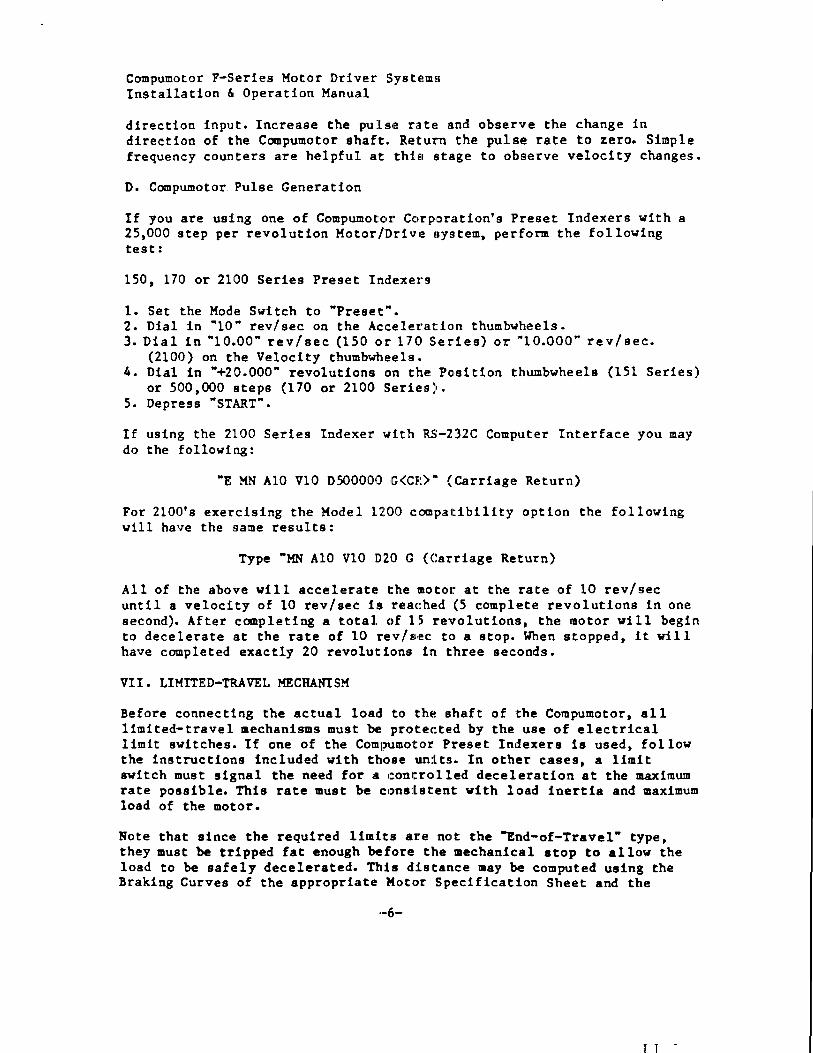
direction input. Increase the pul:!u~ r,He and obser'l7e the change in direction of the Compumotor shaft. Return the pulse rate to zero. Simple frequency counters are helpful at thiel Eltage to observe velocity changes.
D. Compumotor Pulse Generation
If you are using one of Compumot:ClI' CClrp,orcltion's Preset Indexers with a 25,000 step per revolution Motor/Drive! sys:tem, perform the following test:
150, 170 or 2100 Series Preset Indexers
1. Set the Mode Switch to "Preset". 2. Dial in "10" rev/sec on the Acceleration thumbwheels. 3. Dial in "10.00" rev/sec (150 or 1710 Series) or '"10.000" rev/sec.
(2100) on the Velocity thumbwheels" 4. Dial in "+20.000" revolutions on the Po,sition thumbwheels (151 Series)
or 500,000 steps (170 or 2100 Series). 5. Depress "START".
If using the 2100 Series Indexer with RS-232C Computer Interface you may do the following:
"E MN A10 V10 0500000 G<CR)" (Carriage Return)
For 2100's exercising the Model U()O c:ompatibility option the following will have the same results:
Type "MN AlO V10 D20 G (Carriage Return)
All of the above will accelerate the motor at the rate of 10 rev/sec until a velocity of 10 rev/sec is reac:hed (5 complete revolutions in one second). After completing a total ()f 1~5 Ire"olutions, the motor will begin to decelerate at the rate of 10 rev/sec t() a stop. When stopped, it will have completed exactly 20 revolutions in three seconds.
VII. LIMITED-TRAVEL MECHANISM
Before connecting the actual load to the shaft of the Compumotor, all limited-travel mechanisms must be protecte:d by the use of electrical limit switches. If one of the COmp1Jmotor Preset Indexers is used, follow the instructions included with those units. In other cases, a limit switch must signal the need for a e:ontro,lled deceleration at the maximum rate possible. This rate must be c:l)ns:Lstent with load inertia and maximum load of the motor.
Note that since the required limits are nOlt the "End-of-Travel" type, they must be tripped fat enough before: the mechanical stop to allow the load to be safely decelerated. This d:Lstance lIay be computed using the Braking Curves of the appropriate Mot,e,r Specification Sheet and the
T T
Compumotor F-Series Motor/Driver SYEltem!J Installation & Operation Manual
formulas given in App l1cation Note 13. It a1 so may be deteroined empirically by initiating the decele:rati.,:>n cycle in the middle of travel and measuring the distance required to stop.
VIII. DYNAMIC CHARACTERISTICS OF THE COP-fPUHOTOR
A Compumotor is a special case of cl hyblLid poermanent magnet stop motor driven by a 20 KHZ, bi-polar, chopper powelL BiDlplifier. Its complex wave shaping circuitry allows signilicant cOlllpensation for many of the mechanical and electrical imbalances inherent in step motors. The digitally-controlled proportioning ,of current slmul taneously between multiple \Jindings gives high torque Cit llow speed without the jarring accelerations of traditional step motor~l.
The precision of Compumotor's drive proporltielning techniques yie Ids exceptional repeatability while maintaining the open-loop accuracy and ease of use characteristic of steppe!r meltors. The Compumotor shares the dynamic response curve of the stepp~!l~ m()tor ,!lnd its stall characteristics. That Is, full torque under acceleration is developed at a lag angle of approximately l.sO. Loading which cau;ses a larger lag angle \Jill result in the motor losing position.
In cases of severe overloading, the: roto,:r liill lose synchronism wi th the rotating magnetic vector of the stator and the rotor will stall and stop. The Compumotor has been designed to alle"11 ;1 continuous stall condition while overloaded without damage to the GomPUtDotor or the driver. If the motor is stalled, however, the rotating magnetic vector must be stopped by halting the input pulses, and the cause of the overloaded condition remedied before the Compumotor may bE! re~:!lt,iirted and run successfully.
Up to 1.8() of dynamic error under acc~elelration will be recovered when a constant velocity is reached, or wh~m the C01:llpumotor is stopped. How much error is recovered is proportional to' lo,ad friction and depends on the stick-slip characteristics of the lc).id. 'The degree of recovery may therefore have to be determined eiDlpirically. If using Compumotors or step motors in multi-axis systems, the error under load (if excessi ve) could be compensated for in the master con,trol system. Decelerating produces a similar error condition as the motor lea~s the load.
IX. PERIODIC MAINTENANCE
Periodically check the Compumotor lBcnmtlng be) 1 ts and shaft coup lings. The ball bearIngs used in the Compumotor are not sealed but are permanently lubricated and require no maintenance. There are no serviceable items in the COIIlpumotor or maintenance items such all brushes.
The motor strain relief and cable sl1icluld be Jlnspected at appropriate intervals for signs of wearing or excess:[ VI! force being applied to the cable. Tighten both cable connectors at the driver. Check that the driver
-7-
T T
Compumotor F-Series Motor/nriver S,ystl!ml!l Installation & Operation Manual
heatsink is free of dust and dirt and hu a free flow of air over its entire surface.
x. TROUBLESHOOTING
If problems develop in the operation of the Compumotor, refer to the following list of symptoms and c:aLliseSI tl) :I.dentifyor localize the problem:
1. Motor fails to turn
Probable causes:
(a) No AC power (b) Bad connections or bad cables (c) Tripped or faulty limit s:witc:hes - make sure that control signals
are not being inhibited by l:Lm:lt inputs to a preset indexer or supervisory logic.
(d) Load is jammed - remove AC pC)VE!r from the driver and verify that the load can be turned 1ll,a,nual1:,.
(e) No step signal coming to dri17er _. check that a pulse train meeting all requirements for voltage, current and pulse width is available (3.5 to 6V @ llliA. minilDUIlI, 25 mA maximum, 500 nSec pulse width minimum).
(f) Driver ouput is being turned off by Remote Pover Shutdown OptionPin 16 of the input cable to the driver should not be high (ITL level) relative to Pin 17.
(g) Blown driver AC line fUSIE!. - Dtsconnect AC paver from the driver and dismount it from the surfal:e to which it is attached. Remove the four Phillips-head slc:rews l.mlch retain the sheet metal cover on the long sides of the dri ',elt'. Remove the four screws on the short edges of the end plates. Slip off the cover and inspect the fuse., If the fuse is blown, return the un! t for repair.
Notice: Probing of the driver with A.G po\,er applied should never be done by anyone other than COIIIpumo,ltor (Iualified personnel. LETHAL VOLTAGES ARE PRESENT and thelre hi no AC isolation in the driver.
2. Motor stops during acceleratio'n:
Probable cause:
This condition indicates an overlload c:ondition caused by excessi ve torque requirements, too steep an acce!leration ramp, or a gross mislIlatch of load inertia and rotor l.nertJla. Refer to Compulllotor Application Note 13 for calculations of torque. A larger motor and/or lower accelerations lIlay be indicatec!.
3. Motor fa11s to run above 20 rps (12()0 rpm)
-8-
r T
Compumotor F-'Series Motor/Dr! ver Systemls Installation & Operation Manual
This may be due to load/CompulDot'c,r interactions which can stimulate parametric oscillations and IHaUL the Compumotor. The addition of friction, system dampening or mec:hanical redesign to minimize lIIechanical resonances lIIay be required singly or in combination.
4. Motor is jerky, noisy or weak
Check that there are no mechanical problems at the load causing highly variable loading conditions BIt: the Ccx~pumotor shaft. Disconnect the Compumotor from the load and lrun it wi th a dummy load connec ted. If the problem persists, 8ervic:e~ repair jls indicated.
XI. FACTORY SERVICE
To return the Compumotor for repair o,r Ito order replacement parts, obtain the model and s~r1al numbers of the ID'C)tIH' and driver. Call the Compumotor Service Department for return authori:~at:1c'n. In California call collect: (707) 778-1244, otherwise call to,ll free (800) 3.58-9068. Return the Compumotor and Driver, freight prepaid, to::
Note: Please mark both packing slip and packing label with the Return Material Authorization number supplied! by Compumotor.
~II. FURTHER NOTES
Compumotor Corporation is dedicatl!d tlJ be a leader in digital motion control. We invite your problems t que:~tions or comments.
This manual has been designed to provJlde a,n introduction for the user with typ lc.:t 1 app li<:a t ions. Signi ficant dep.lrtur,es from the operati ng parameters outlined here are possible. If you ha',e a volume requirement for our products (of over 250 per year) we would like to discuss your specific needs.
Call or write:
Parker Compumotor 5500 BUSiness Park Drive Rohnert Park, CA 94928 (707) 584-7558 (800) 358-9068 RMA #
In California ,call collect: (/07) 584-7558 Outsid~ C~ltfornia. call toll free: (800) 358-9068
-9-
T 1
Compumotor F-Series Motor/Driver Systems Installation & Operation Manual
XIII. SPECIFICATIONS
Environmental Specifications:
31' . 0 0 0 Operating: Driver - '-la F (0-50 C) ambient assumes driver fins mounted vert: ic:all YJ
convection cooling. Maximum. fin c~
temp. - 150 F (50) a to 95% hUDlicii ty. non-condensing
Motor .- 3f-lOLi.op (o!50o) ambient - assumes convection cooling. Ma~:imUlll. case temp. (measured mid-case) - 212 (101f C) o to 95% hualidlity. non-cond~nsing
Storage: {I C 0 c
-40 to l85 F (-40 to 85 C)
Electrical Specifications:
Input power: TTL Inputs:
105 to 125 VAc 50/60 Hz with brownout protection 3.5 to 6.0V pulse height
Driver Dimensions: Weight: Height: Length: Width:
~500 :cLSec pulse width minimum 20 mA tlllinimum current :750 KHZ maximum pulse rate
4 lbs. (1.82 kg) IL063 in.(10.32 em) 13.25 in. (20.96 em) ~)'38 in. (13.67 011)
Motor Specifications:
Rotor Inertia:
OI-inl. kg-cm1
FSi'-83
1 •. 28 .2~34
F83-49
.48
.008
Tc)rque: see appendix n fClr sp4!ed torque curves
-10-
T 1
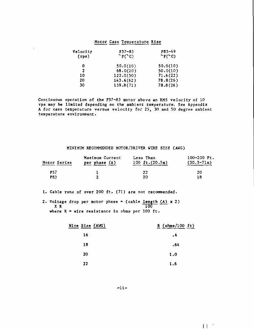
Velocity (rps)
o 2
10 20 30
F57-83 ' .. F('C)
50.0(1.0) 6:~ .0(2:0)
122.0 (50]1 14.3.6 (62 JI
1:59.8(71)
F83-49 .... F( .... C)
50.0(10) 50.0(10) 71.6 (22) 78.8(26) 78.8(26)
Continuous operation of the F57-83 motor above an RMS velocity of 10 rps may be limited depending on the ambIent temperature. See Appendix A for case temperature versus velocity for 25, 30 and 50 degree ambient temperature environment.
MINIMUM RECOMMENDED MOTOR/DRIV1!!:R WIRE SIZE (AWG)
Motor Series
F57 F83
Maximum Current: .E.!:.! phase (A)
1 2
Les:~ Than ~OO ft.(20.5m)
22 20
1. Cable runs of over 200 ft. (7'1) are n()t recommended.
2. Voltage drop per motor phase ., (c~!lble length (A) x 2) XR 100
where R • wire resistance in ohmsi per 100 ft.
100-200 Ft. (30 .S-11m)
20 18
Wire Size (A~) R (ohms/lOa ft)
16 .4
18 .64
20 1.0
22 1.6
·-ll-
T 1 -
u (!) LrJ 0
I
n: 2 LrJ .... LrJ VI
() a:: 0 .... 0 :i
30
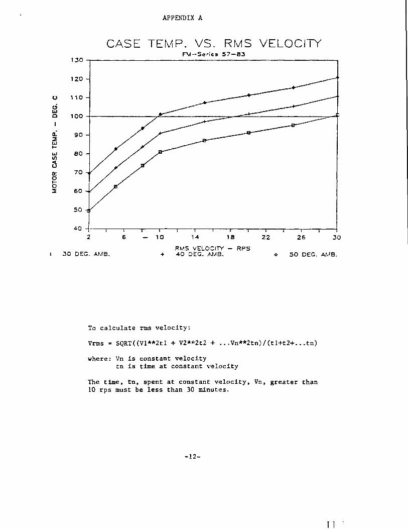
APPENDIX A
CASE TEt\AP. VS. IRMS VELOCITY F'M--SeriC9 5,7-83
130
120
110
100 -+----------,.~-----------........ =----------,,-~ ~-----
90 --e------
80
70
60
50
40 ---r--·~---r_-~-_r--'-.___-.___'~I---~--~---r-~---~~
2 6 10 'r·4 18 22 26 .30
Rt.lS VELOCITY - RPS DEG. AUB. + 40 DEG. AMB. 50 DEG. At,IB.
To calculate rms velocity::
Vrms :or SQRT«Vl**Ztl + V2*~'2t2 -+ ••• Vn**2tn}/(tl+tZ+ .•• tn)
where: Vn is constant velod.ty t.n is time at consta,nt velocJlty
The time, tn, spent at constant velocity, Vn, greater than 10 rps must be less than 30 minutes.,
-12·-
T T ..
p::j
X H
ffi p..
~
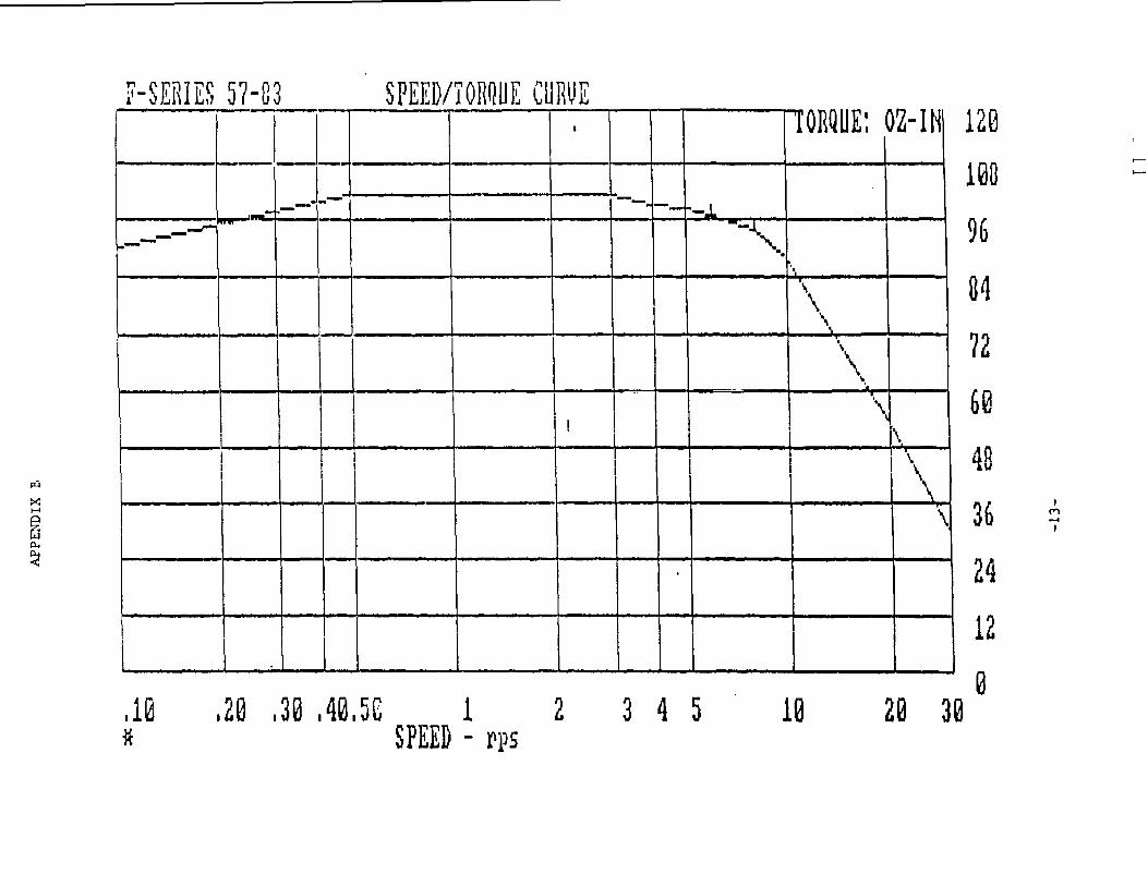
it-SERIES 57-03 SPEED/TORQUE CURVE
TI_ I IORQUE: OZ-IN
. __ L -- --. --1--.1
120
l~G
_---r- "" 1--- -~. .. 96
, . ... \ 31
I --!---l \
L \\ \
I , ., '.
\ \ \ \ I Iii i \i ____ L ~ I '-___ J~ ___ ~L' 1 __ LI 1 . ____ f....;...\_
I--~-
I \. 'i \ I .
~ I
\
72
60 dQ .,\1
36
24
!
. . ! I I I I 1_- _____ _ _
12
.10 *
.20 .30 .4~.5C 1 2 3 4 5 10 o
2~ 3~ SPEED - ~p5
t--
>--
• M ...... •
""' ... c o !.J -~
>< H
ffi p..
~
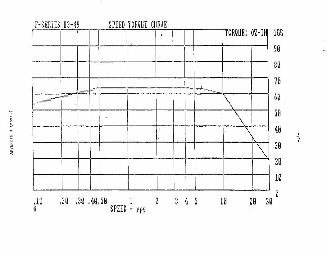
F-SERIES 83- 119 SPEED TORQUE CURVE I TORQUE: OZ-IN 1GG
- 90 .---8G
7G I
-- -- --- I 2-- \ -.--- \, .. \.
! I . ' .
I __ I
I I I I \\
I_~ __ L ___________ I__ ___ '.
r---l 1 \ __ 1 I ."". • •
-I I •
HjjJ . II I II I t\:1
6e r'1"\ J\j
4~ i
-<7 ....
3~ I
28
I I I I I I le ~
.10 ,20 .30 .40,50 1 2 3 4 5 le 23 3~ * SPEED - ~P5
?ULSE SO:.J~CE OR !t;JEXEiR
cr.:"S SIS G~O:.;"'()
STEP + OUTPUT
STEP -RETURN
D:;:<ECTION + OUTPUT
D:RECTION -RETURN
SHUTDOWN + OUTPUT
SHUTDCSN -RETUi'\N
APPENDIX C
DF\/vER
SHIELD
~
'--"
-15-
T 1
LIMITED WARRANTY.
O~ 11,.,.1 Q-Z!al 5/8.3
SeUer WilTTants that the products sold will be free /rom defects in matenal and worlcmansrup and perform to Seller's apphc.a.bl~! pubhshed specmcatlons for a penod of I yeaz from do!te of shipment. The liability of Seller hereu~lder shiill be liIlllteci to replaonq or repauinq. &t its option. any defective uruU which are retLLmed F. 0 B. Seller's plant, Petaluma. Califorrua. In no C4Se are products to be returned withmJt hut obtc!lninq permission and a c:ustcmer retum order number from SelleL In no event !.h.all Seller be liable for any consequentiAl or incidental damages,
EqUlpment or parts which haTt! ~II su.bject to abuse. misuse, accident, alteration, neqlect, unauthonzed rep&l1 or installabon aze not l:overed by WilTTanty, Seller shall mue the hnal determinabon as to the e:usten,'e and c:ause oJ any alleged defect. No liability is assumed for expendable items such &S lamps lLIld fuses. Nc) wilTTanty is made with respect to custom eqWpment or products produced to Buyer"s speaficabons except as spetihcally stated In wribng by Seller in the contract for such C'Llstolll equipment.
This wilTTanty is the only WilTTa.n~ made by Seller with respect to the goods delivered hereunder, and may be modibed o:r a.rD'e'nded only by a wntten instrument Slgned by a duly authorized offic-er of Seller and accepted by BuyeL
ucept as hereinabove prOvided SELLER l'.1AKES NO WARRANTIES. EXPRESS OR IMPUED, INCLUDING ANY WARRANTY OF MERCHANTABIUTY OR FITNESS FOR A PARTICULAR PURPOSE.
The leader in microstepping technology
~(OmiPUmc)t:O=i ~~ ~~[P@~M~[KQ)Oll-
(707) ne·1244 1 (1lCX)) 358·90681 n.x 5 IO·744211 5
r T
T 1 ..
CompUlDotor Div of Parker Hannifin
AP'F'ENDU .A
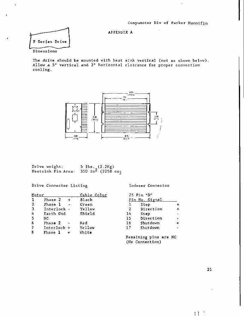
F Series Drive
Dimensions
The drive should be mounted with heat sink vertical (not as shol.'Tl below). Allow a 5" vertical and 3" horizontal clearance for proper convection cooling.
D T o .0 o - ,
IL-0_ °_0 -,--1 ~-,,'c~I~ ~---,~~:.
Drive we ight: Heatsink Fin Area:
5 lbs. (2.2Kg) 350 in2 (2258 em)
Drive Connector Listing
Hotor Cable Color 1 Phase 2 + Black 2 Phase 1 Green 3 Interlock - Yellow 4 Earth Gnd Shield 5 NC 6 Phase 2 Red 7 Interlock + Yello,", 8 Phase 1 + 1.."11 i te
Indexer Connector
25 Pin nD" Pin No. Signal 1 Step 2 Direction
14 Step 15 Direction 16 Shutdol.'Tl 17 Shutdo\o1ll
Remaining pins are (No Connection)
+ +
+
NC
21
T T
I
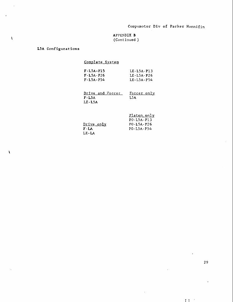
L5A Configurations
\
Gompumotor Div of Parker Hannifin
AP1'ENDIX B (Cont inlJed )
Complete S'y-stem
F-L5A-P15 F-L5A-P26 F-L5A-PS4
Drive and ForceI~ F-L5A LE-LSA
Drive only F-lA LE-lA
LE-LSA-P13 LE-LSA··P26 LE-LSA··PS4
Forcer onlY LSA
,Platen Olill PO-LSA-P13 PO-LSA-P26 PO-LSA-P54
29
T 1 ..
30
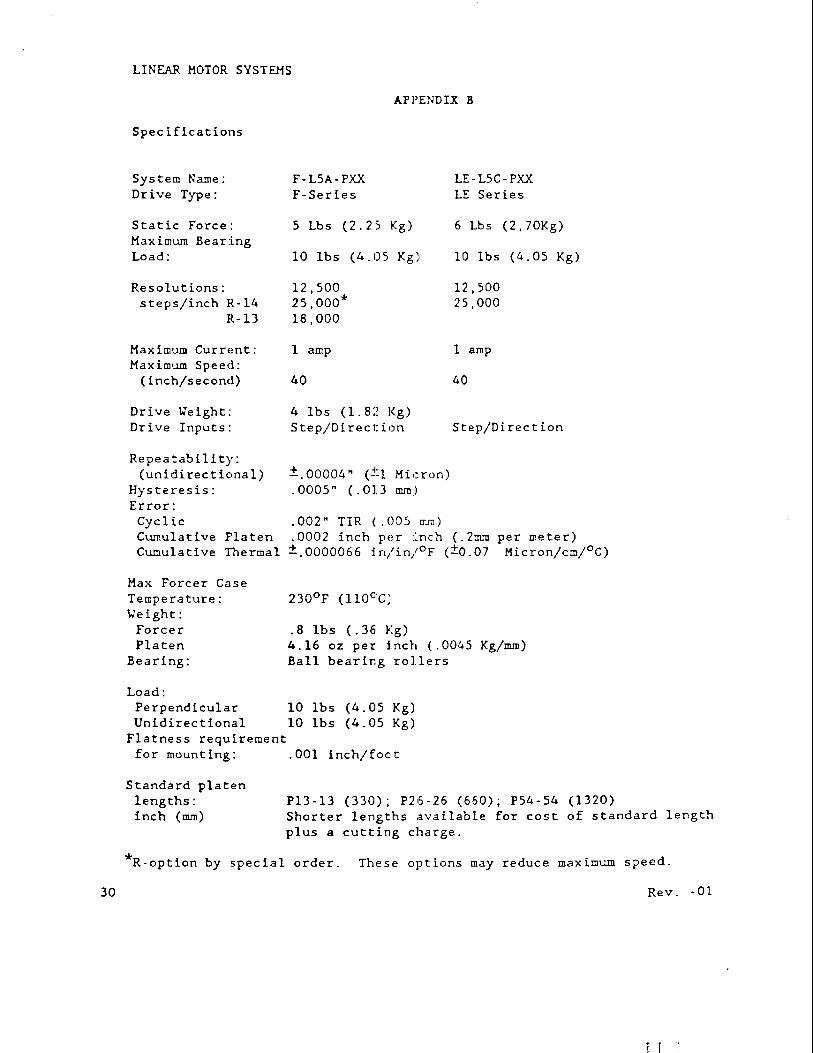
LINEAR MOTOR SYSTEMS
Spec ifications
System Name: Dr ive Type:
Static Force: Maximum Bearing Load:
Resolutions: steps/inch R-14
R-13
MaximWD Current: MaximWD Speed:
(inch/second)
Drive Weight: Drive Inputs:
Repea tab i 11 t)': (unidirectional)
Hysteresis: Error:
APPENDIX B
F-L5A-PXX F-Series
5 Lbs (2.25 Kg)
10 Ibs (4.05 Kg)
12,500 25,000* 18,000
1 amp
40
4 1bs (1. 82 Kg) Step/Direction
±.00004" (±l Micron) .0005" (.Ol.] !DIn)
LE-L5C·PXX LE Series
6 Lbs (2,70Kg)
10 Ibs (4.05 Kg)
12,500 25,000
1 amp
40
Step/Direction
Cyclic .002" TIR (.005 =) Cumulative Flaten .0002 inch per inch (.2mm per meter) Cumula tive Thermal ±.0000066 in/in/oF eta. 07 Micron/cm/°C)
Max Forcer Case Temperature: \.leight:
Forcer Platen
Bearing:
Load: Perpendicular Unidirectional
Flatness requirement
.8 lbs (.36 Kg) 4.16 oz per i.nch (.0045 Kg/rnm) Ball bearing rollers
10 lbs (4.05 Kg) 10 1bs (4.05 Kg)
for mounting: .001 inch/foot
Standard platen lengths: P13-l3 (330); P26-26 (660); P54-54 (1320) inch (lDlD) Shorter lengths available for cost of standard length
plus a cutting charge.
*R-option by special order. These options may reduce maximum speed.
Rev. -01
T T
\
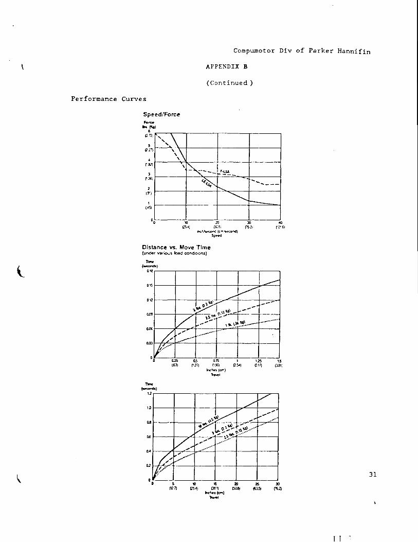
Compumotor Div of Parker Hannifin
Al'PENDIX B
(Continued)
Performance Curves
Speed!Force
I" ,\ " \\
2 (91)
I CASI
:
\~,
10 20 30
-
~A) ~":E! (1IJil ilnd\~'1(~ (c,.,."IoIr-cD~
Distance YS. Move 'Time (under various load cond~iol\S)
n-IN'<O"'do )
O,!
5~_
-.
.,~ '\ ' v.
QlI3 ~ .," . ......-.~. W/ '/ ....
D.2!. n5
1.0
Il~
(I ~JJ)
hc"'r·ltJ"I'l) 'h~
-,....._ ...... -~!"'.~~ .. -
..... _--
~--
-------_ ...
"-15 (J.B1)
~ .~ .~ ""~/--4-_~"~~."':: ... :"" .. ~.
"YI (I.\~~ .... ~\ ••••
OA
c
'" ,~~.""". (\~ ..... . --;;;;r- -~: ... "
",~ ......
V'
Vv ","" .." ......... ----+-----+-
Z~ ~., ~ .... ..-/
~~ ... o 5
(1<7) 10 I~, 2Il
~'AJ P!~ I~ _.(em)
.... ""
31
T T
32
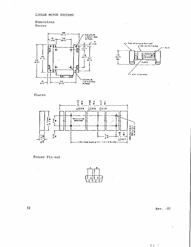
LINEAR MOTOR SYSTEMS
Dimensions Forcer
Platen
1 ·L......-+-!-+--8 --- -
Forcer Pin-out
5-32 lI'O:';1I • 211~)31 D~ I') I'Iaa.
T 1
p." "
Rev. -01
NOTE:
Cornpumotor Div of Parker Hannifin
APPENDIX C
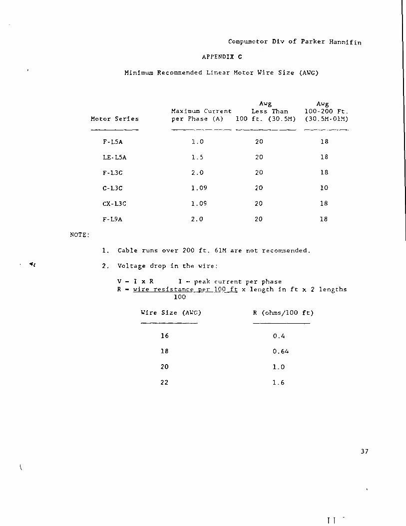
Minimum Recommended Linear Motor \.Tire Size (A\.TG)
Awg Awg MaxiIDum Current Less Than 100-200 Ft.
Motor Series per Phas,~ (A) 100 ft. (30.5M) (30. 5M- OlM)
-----------
F-L5A 1.0 20 18
LE-LSA 1.5 20 18
F-L3C 2.0 20 18
C-L3C 1.09 ~'O 10
CX-L3C 1. 09 20 18
F-L9A 2.0 20 18
1. Cable runs over 200 ft. 6lM are not recommended.
2. Voltage drop in the wire:
V - I x R I - peak current per phase R - wire resistance ..Qfl~_100 ft x length in ft x 2 lengths
100
\.Tire Size (A\,;'G) R (ohms/laO ft)
16 0.4
18 0.64
20 1.0
22 1.6
r T "
37
38
LINEAR MOTOR SYSTEMS
J~PPENDIX C (Continued)
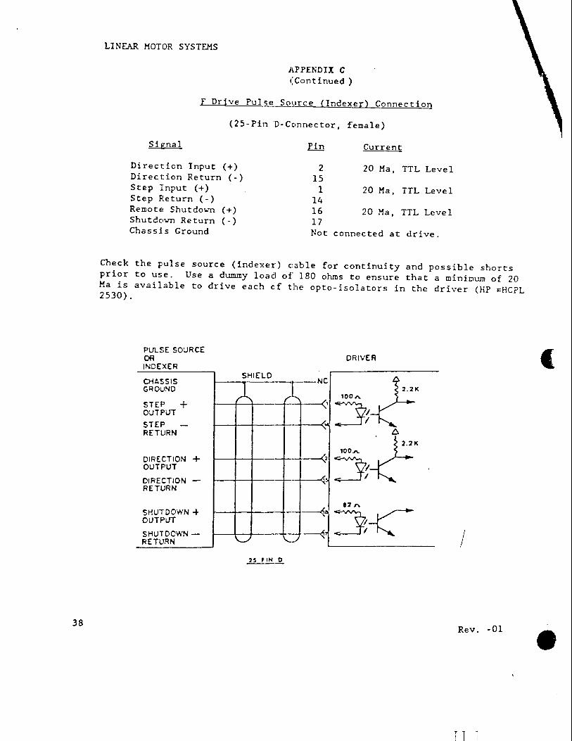
f Drive Pulse Soyrce (Indexer) Connection
(25-Pin D-Connector, female)
Signal rin .Current
Direction Input (+) 2 .20 Ma, TTL Level Direction Return ( -) 15 Step Input (+) 1 20 Ma, TTL Level Step Return ( - ) 14 Remote Shutdololl (+) 16 20 Ma, TTL Level ShutdololTI Return ( -) 17 Chassis Ground Not connected at drive.
Check the pulse source (indexer) c:able for continuity and possible shorts prior to use. Use a dummy load of 180 ohms to ensure that a minimum of 20 Ma is available to drive each of the opto-isolators in the driver (HP ~HCPL 2530).
PUlSE SO:.JRCE OR INDEXER
CHASSIS GROllND
STEP + OUTPUT
STEP -RETURN
DIRECTION + OUTPUT
DIRECTION -RETURN
SHUTDOWN + OUTPUT
SHUTDOWN -RETURN
DRIVER
SHIEL
A [) _[ __ INC~ ~ 2.21( 100 ....
- --<, 3; - -~ D.
-~5:~'
I
Rev. -01
T 1
(
•
1-40
1::30
120
no ..... 100 W ::r C] 90 Q; :J: 80 ~ III 70 1.1 w 60 a::: '-' w
50 0
-40
,)0
20
10 0
\
Compumotor Div of Parker Hannifin
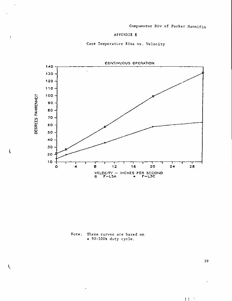
A}'FENDIX E
Case Temperature Rise vs. Velocity
C:C)NTINUC)U$ OPERATION -----
/ //
,;
I ---,----,-. - I
-4 e 12 16 20
V[LOCI1Y - INCHES PER SECOND 0 F"-L5A + f"-DC
Note: These curves are b':lsed on a 90-100% duty cycle.
/i
24 28
39
r 1
.--LJ :r z w 0::
~ 1:3 w 0:: 0 w 0
LINEAR MOTOR SYSTEMS
170
1150
1~0
140
1:30
120
110
100
gO
eo
70
EO
2
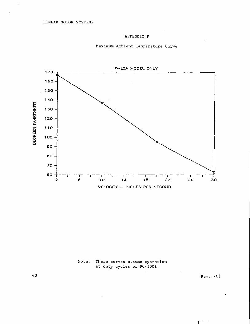
APPENDIX F
Maximum Ambient TE:rnperature Curve
F"--l,5.A. ~IDDEL ONLY -------
'~
~ I ----.---,- T
6 10 1-4 18 22
VELOCITY - INCHES PER SECOND
Note: These curves ,assume operation at duty cycles of 90-100%.
26 :30
40 Rev. -01
r 1
Compumotor Div of Parker Hannifin
APHNDIX G
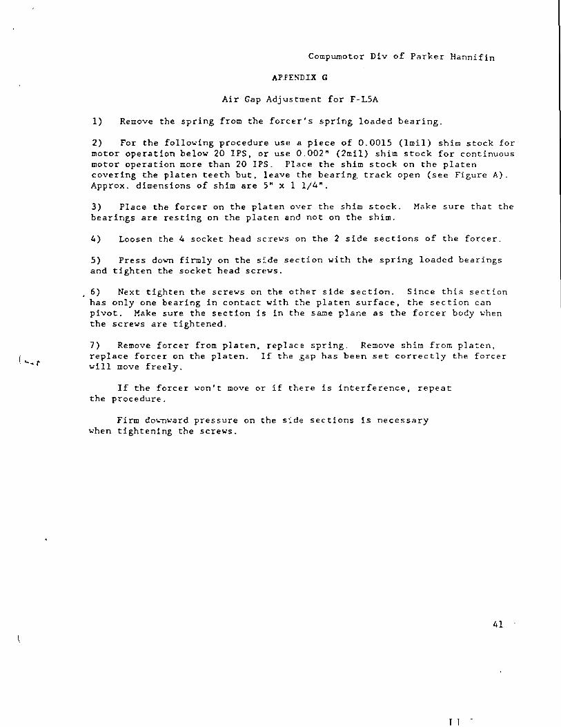
Air Gap Adjustment for F-L5A
1) Remove the spring from the forcer's spring loaded bearing.
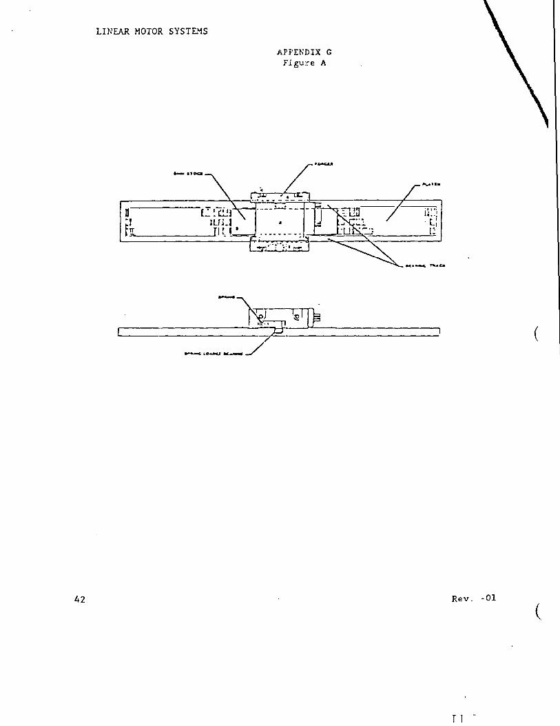
2) For the following procedure use a piece of 0.0015 (lmil) shim stock for motor operation below 20 IPS, or use 0.002" (2mil) shim stock for continuous motor operation more than 20 IPS. Place the shim stock on the platen covering the platen teeth but, leave the bearing track open (see Figure A). Approx. dimensions of shim are 5" x I 1/4".
3) Place the forcer on the platen over the shim stock. Make sure that the bearings are resting on the platen and not on the shim.
4) Loosen the 4 socket head screws on the 2 side sections of the forcer.
5) Press dl")wn firmly on the sfde section with the spring loaded bearings and tighten the socket head SCrE!WS.
6) Next tighten the screws on the other side section. Since this section has only one bearing in contact with the platen surface, the section can pivot. Make sure the section is in the !Same plane as the forcer body when the screws are tightened.
7) Remove forcer from platen, replace spring. Remove shim from platen, replace forcer on the platen. If the gap has been set correctly the forcer will move freely.
If the forcer won't move or if there is interference, repeat the procedure.
Firm dO\.-nward pressure on the side sections is necessary when tightening the screws.
T T
41
42
LINEAR MOTOR SYSTEMS
APPENlDIX G Figure A
r---.-_-_~~=b,~~_~~"'-·-___ ----, [ r- (
Rev. -01
(
r 1 "

![AC Servo Motor Driver Operating Manual - Panasonic · PDF fileAC Servo Motor Driver MINAS AIII-series Operating Manual [Be sure to give this instruction manual to the user.] DV0P3450](https://img.pdfslide.tips/doc/110x75/5a7128ec7f8b9a98538ca6c1/ac-servo-motor-driver-operating-manual-panasonic-nbsppdf-fileac-servo.jpg)


![円弧型リニアサーボモータ Arc type Linear Servo Motor Compass Motor...5 Servo driver / Controller [ CⅡ series ] [ VCⅡseries ] Servo driver / Controller Line up VCⅡ-D](https://img.pdfslide.tips/doc/110x75/60d73f7f99be0c5f5558ebe2/ffffoeff-arc-type-linear-servo-compass-motor-5-servo.jpg)