Embed Size (px)
Citation preview

Construction Manual for Power-Inverter Air Conditioner
Issued in 2003
For R410A
Power-Inverter.qxp 04.7.15 5:38 PM Page 1
Contents
1. Difference between Refrigerant R22 and Alternative Refrigerant R410A················································42. Difference in Material of Refrigerant Pipe between R22 and R410A ······················································53. Installation Procedures and Cautions on Construction············································································64. Airtight Test ··············································································································································75. Vacuuming (Vacuum Drying)····················································································································86. Checking the Gas Leakage····················································································································107. Reusing the Existing Pipe ······················································································································118. Tools for Installation ······························································································································159. Tools for Refrigerant Charge··················································································································16
10. Checking the Operation Condition ········································································································1711. Capacity correction ································································································································1812. Field electrical wiring (Power wiring specification) ················································································1913. Check List for Existing Pipe Work ··········································································································20
Power-Inverter.qxp 04.7.15 5:38 PM Page 2
3
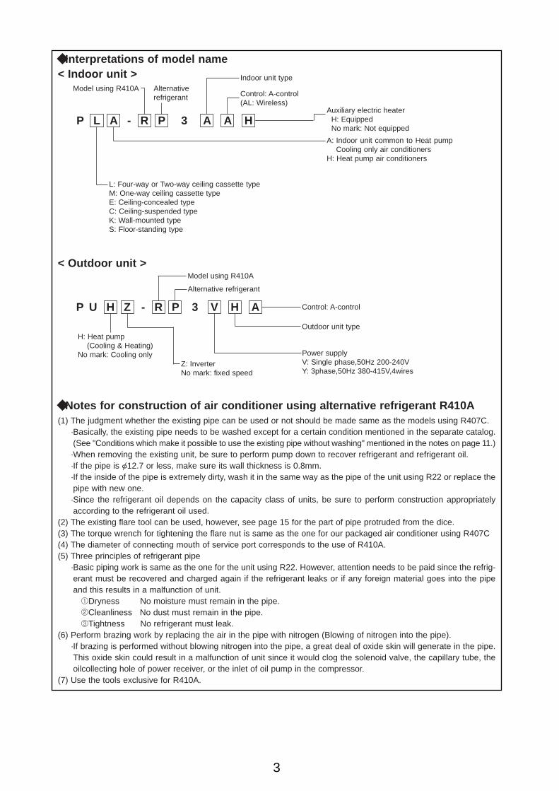
◆Interpretations of model name< Indoor unit >
P L A - R P 3 A A H
Model using R410A Alternativerefrigerant
Indoor unit type
Control: A-control(AL: Wireless)
Auxiliary electric heaterH: Equipped No mark: Not equipped
A: Indoor unit common to Heat pumpCooling only air conditioners
H: Heat pump air conditioners
L: Four-way or Two-way ceiling cassette typeM: One-way ceiling cassette typeE: Ceiling-concealed typeC: Ceiling-suspended typeK: Wall-mounted typeS: Floor-standing type
< Outdoor unit >
P U H Z - R P 3 V H A
Model using R410A
Alternative refrigerant
Control: A-control
Z: InverterNo mark: fixed speed
H: Heat pump(Cooling & Heating)
No mark: Cooling only
(1) The judgment whether the existing pipe can be used or not should be made same as the models using R407C.·Basically, the existing pipe needs to be washed except for a certain condition mentioned in the separate catalog.(See "Conditions which make it possible to use the existing pipe without washing" mentioned in the notes on page 11.)·When removing the existing unit, be sure to perform pump down to recover refrigerant and refrigerant oil. ·If the pipe is {12.7 or less, make sure its wall thickness is 0.8mm.·If the inside of the pipe is extremely dirty, wash it in the same way as the pipe of the unit using R22 or replace thepipe with new one.·Since the refrigerant oil depends on the capacity class of units, be sure to perform construction appropriatelyaccording to the refrigerant oil used.
(2) The existing flare tool can be used, however, see page 15 for the part of pipe protruded from the dice.(3) The torque wrench for tightening the flare nut is same as the one for our packaged air conditioner using R407C(4) The diameter of connecting mouth of service port corresponds to the use of R410A.(5) Three principles of refrigerant pipe
·Basic piping work is same as the one for the unit using R22. However, attention needs to be paid since the refrig-erant must be recovered and charged again if the refrigerant leaks or if any foreign material goes into the pipeand this results in a malfunction of unit.1Dryness No moisture must remain in the pipe.2Cleanliness No dust must remain in the pipe.3Tightness No refrigerant must leak.
(6) Perform brazing work by replacing the air in the pipe with nitrogen (Blowing of nitrogen into the pipe).·If brazing is performed without blowing nitrogen into the pipe, a great deal of oxide skin will generate in the pipe.This oxide skin could result in a malfunction of unit since it would clog the solenoid valve, the capillary tube, theoilcollecting hole of power receiver, or the inlet of oil pump in the compressor.
(7) Use the tools exclusive for R410A.
Outdoor unit type
Power supplyV: Single phase,50Hz 200-240VY: 3phase,50Hz 380-415V,4wires
◆Notes for construction of air conditioner using alternative refrigerant R410A
Power-Inverter.qxp 04.7.15 5:38 PM Page 3
4
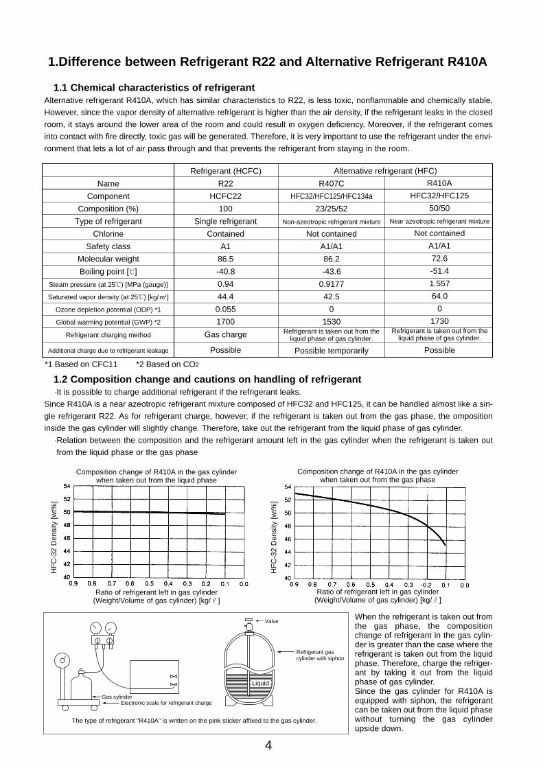
1.1 Chemical characteristics of refrigerantAlternative refrigerant R410A, which has similar characteristics to R22, is less toxic, nonflammable and chemically stable.
However, since the vapor density of alternative refrigerant is higher than the air density, if the refrigerant leaks in the closed
room, it stays around the lower area of the room and could result in oxygen deficiency. Moreover, if the refrigerant comes
into contact with fire directly, toxic gas will be generated. Therefore, it is very important to use the refrigerant under the envi-
ronment that lets a lot of air pass through and that prevents the refrigerant from staying in the room.
*1 Based on CFC11 *2 Based on CO2
Name
Component
Composition (%)
Type of refrigerant
Chlorine
Safety class
Molecular weight
Boiling point [;]
Steam pressure (at 25;) [MPa (gauge)]
Saturated vapor density (at 25;) [kg/K]
Ozone depletion potential (ODP) *1
Global warming potential (GWP) *2
Refrigerant charging method
Additional charge due to refrigerant leakage
R22
HCFC22
100
Single refrigerant
Contained
A1
86.5
-40.8
0.94
44.4
0.055
1700
Gas charge
Possible
R410A
HFC32/HFC125
50/50
Near azeotropic refrigerant mixture
Not contained
A1/A1
72.6
-51.4
1.557
64.0
0
1730Refrigerant is taken out from the
liquid phase of gas cylinder.
Possible
R407C
HFC32/HFC125/HFC134a
23/25/52
Non-azeotropic refrigerant mixture
Not contained
A1/A1
86.2
-43.6
0.9177
42.5
0
1530Refrigerant is taken out from the
liquid phase of gas cylinder.
Possible temporarily
Refrigerant (HCFC) Alternative refrigerant (HFC)
1.2 Composition change and cautions on handling of refrigerant·It is possible to charge additional refrigerant if the refrigerant leaks.
Since R410A is a near azeotropic refrigerant mixture composed of HFC32 and HFC125, it can be handled almost like a sin-
gle refrigerant R22. As for refrigerant charge, however, if the refrigerant is taken out from the gas phase, the omposition
inside the gas cylinder will slightly change. Therefore, take out the refrigerant from the liquid phase of gas cylinder.
·Relation between the composition and the refrigerant amount left in the gas cylinder when the refrigerant is taken out
from the liquid phase or the gas phase
Gas cylinder
The type of refrigerant "R410A" is written on the pink sticker affixed to the gas cylinder.
Liquid
Electronic scale for refrigerant charge
Refrigerant gas cylinder with siphon
ValveWhen the refrigerant is taken out fromthe gas phase, the compositionchange of refrigerant in the gas cylin-der is greater than the case where therefrigerant is taken out from the liquidphase. Therefore, charge the refriger-ant by taking it out from the liquidphase of gas cylinder.Since the gas cylinder for R410A isequipped with siphon, the refrigerantcan be taken out from the liquid phasewithout turning the gas cylinderupside down.
HF
C-3
2 D
ensi
ty [
wt%
]
HF
C-3
2 D
ensi
ty [
wt%
]
Composition change of R410A in the gas cylinderwhen taken out from the liquid phase
Ratio of refrigerant left in gas cylinder (Weight/Volume of gas cylinder) [kg/r]
Composition change of R410A in the gas cylinderwhen taken out from the gas phase
Ratio of refrigerant left in gas cylinder (Weight/Volume of gas cylinder) [kg/r]
1.Difference between Refrigerant R22 and Alternative Refrigerant R410A
Power-Inverter.qxp 04.7.15 5:38 PM Page 4
5
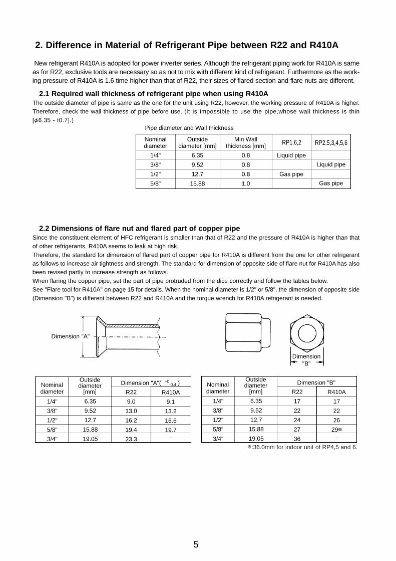
2. Difference in Material of Refrigerant Pipe between R22 and R410A
New refrigerant R410A is adopted for power inverter series. Although the refrigerant piping work for R410A is sameas for R22, exclusive tools are necessary so as not to mix with different kind of refrigerant. Furthermore as the work-ing pressure of R410A is 1.6 time higher than that of R22, their sizes of flared section and flare nuts are different.
2.1 Required wall thickness of refrigerant pipe when using R410AThe outside diameter of pipe is same as the one for the unit using R22, however, the working pressure of R410A is higher.Therefore, check the wall thickness of pipe before use. (It is impossible to use the pipe,whose wall thickness is thin[{6.35 - t0.7].)
Nominal diameter
1/4"
3/8"
1/2"
5/8"
Outside diameter [mm]
6.35
9.52
12.7
15.88
Min Wall thickness [mm]
0.8
0.8
0.8
1.0
Liquid pipe
Gas pipe
RP2.5,3,4,5,6
Pipe diameter and Wall thickness
RP1.6,2
Liquid pipe
Gas pipe
2.2 Dimensions of flare nut and flared part of copper pipeSince the constituent element of HFC refrigerant is smaller than that of R22 and the pressure of R410A is higher than thatof other refrigerants, R410A seems to leak at high risk.Therefore, the standard for dimension of flared part of copper pipe for R410A is different from the one for other refrigerantas follows to increase air tightness and strength. The standard for dimension of opposite side of flare nut for R410A has alsobeen revised partly to increase strength as follows.When flaring the copper pipe, set the part of pipe protruded from the dice correctly and follow the tables below. See "Flare tool for R410A" on page 15 for details. When the nominal diameter is 1/2" or 5/8", the dimension of opposite side(Dimension "B") is different between R22 and R410A and the torque wrench for R410A refrigerant is needed.
Dimension "A"
Dimension "B"
1/4"
3/8"
1/2"
5/8"
3/4"
Nominal diameter
Outside diameter
[mm]
Dimension "A"( )
6.35
9.52
12.7
15.88
19.05
R22
9.0
13.0
16.2
19.4
23.3
R410A
9.1
13.2
16.6
19.7
-0.4+0
1/4"
3/8"
1/2"
5/8"
3/4"
Nominal diameter
Outside diameter
[mm]
Dimension "B"
6.35
9.52
12.7
15.88
19.05
R22
17
22
24
27
36
R410A
17
22
26
29w
w:36.0mm for indoor unit of RP4,5 and 6.
Power-Inverter.qxp 04.7.15 5:38 PM Page 5

6
3.Installation Procedures and Cautions on Construction
Checking the refrigerant used
Making the cons-truction drawing
Checking the con-struction place
Inserting the sleeves
Installing the indoor unit
Installing the outdoor unit
Drain pipe work
Duct work
Heat insulation work
Electrical work
Explanation of comple-tion of installation and operation method to
customers
Connecting the refrigerant pipe
Preparation before construction
Refrigerant pipe work
Airtight test
Vacuuming
Charging the add-itional refrigerant
Checking the gas leakage
Test run
Check and grasp the characteristics of refrigerant used, and be sure to charge the specified refrigerant if the ref-rigerant needs to be charged.
4
1Use the refrigerant pipe whose wall thickness is specified in the page5.2Prepare the following tools exclusive for R410A beforehand. (For installation) Gauge manifold ·Flare tool ·Charge hose ·Vacuum pump ·Backflow prevention device (for vacuum pump) (For refrigerant charge) ·Electronic scale for refrigerant charge ·Refrigerant gas cylinder ·Charge mouth for refrigerant gas cylinder
Changes and cautions about construction procedures of unit using alternative refrigerant. Reasons Ref. page
Observe the followings to keep the inside of pipe clean and airtight.1Use the pipe whose inside is clean.2Do not let any foreign material go into the pipe when leaving the pipe unconnected.3Flare the pipe closely.4Apply the specified oil to the flared part of pipe. (Ester oil, ethereal oil and alkyl benzene oil, etc.)5Check the dimension of opposite side and shape of flare nut.6Use the torque wrench to tighten the pipe securely.7Blow nitrogen into the pipe when brazing is performed.8Before connecting the pipe to the unit, discharge the air in the pipe from the pipe connections.
1Apply the specified oil to the flared part of pipe.
(Ester oil, ethereal oil and alkyl benzene oil, etc.)
2Use the torque wrench to tighten the pipe securely.
1Use nitrogen gas to raise the pressure to the designed pressure of unit, and perform the airtight test for 24 hours.
1Use the vacuum pump equipped with a backflow pre- vention function or use the conventional vacuum pump together with a backflow prevention device.2Perform vacuuming fully (for about 1 hour or more after the low pressure has reached -0.1Mpa.). Do not use any refrigerant to purge air.
1Take out R410A from the liquid phase of gas cylinder. (If the gas cylinder with siphon is used, turning it upside down is not necessary.)2Use the gauge manifold and charge hose exclusive for R410A.
Use the refrigerant leak detector for alternative refrigerant.
WIf the refrigerant other than the specified one is used, the unit could malfunction.
WRequiredwithstand pressure can be secured.WThe size of screw for service port is changed from 7/16 UNF to 1/2 UNF. WThe materials suitable for HFC refrigerant are used.WWrong use of R22 is avoided.
WIf the oil in the vacuum pump flows backward into the unit, the unit could malfunction.
WIf there is foreign material or moisture in the pipe, the cooling effect could be insufficient or the comp- ressor could malfunction. WIf the refrigerant leaks, the unit could stop due to abnormality or the unit's capacity could beinsufficient.
WIf the refrigerant leaks, the unit could stop due to abnormality or the unit's capacity could be insufficient.
WIf the refrigerant leaks, the unit could stop due to abnormality or the unit's capacity could be insufficient.
WIf the oil in the vacuum pump flows backward into the unit, the unit could malfunction.
WRemoving moisture and air fully prevents oil deterioration.
WThe conventional refrigerant leak detector cannot detect R410A.
For units equipped with the replacement filter (RP4,RP5,RP6), perform pipe washing operation in the cooling mode for about 2 hours.
WThe replacement filter recovers chemical compound containing chlorine remained in the pipe.
WIf R410A is taken out from the gas phase, the composition of refrigerant charged changes, and the unit could stop easily due to abnormality or the unit's capacity could be insufficient easily.WWrong charge of refrigerant is avoided.
5
8
9
10
16
17
5
11
12
13
14
16
7
8
9
4
17
10
17
14
Power-Inverter.qxp 04.7.15 5:38 PM Page 6
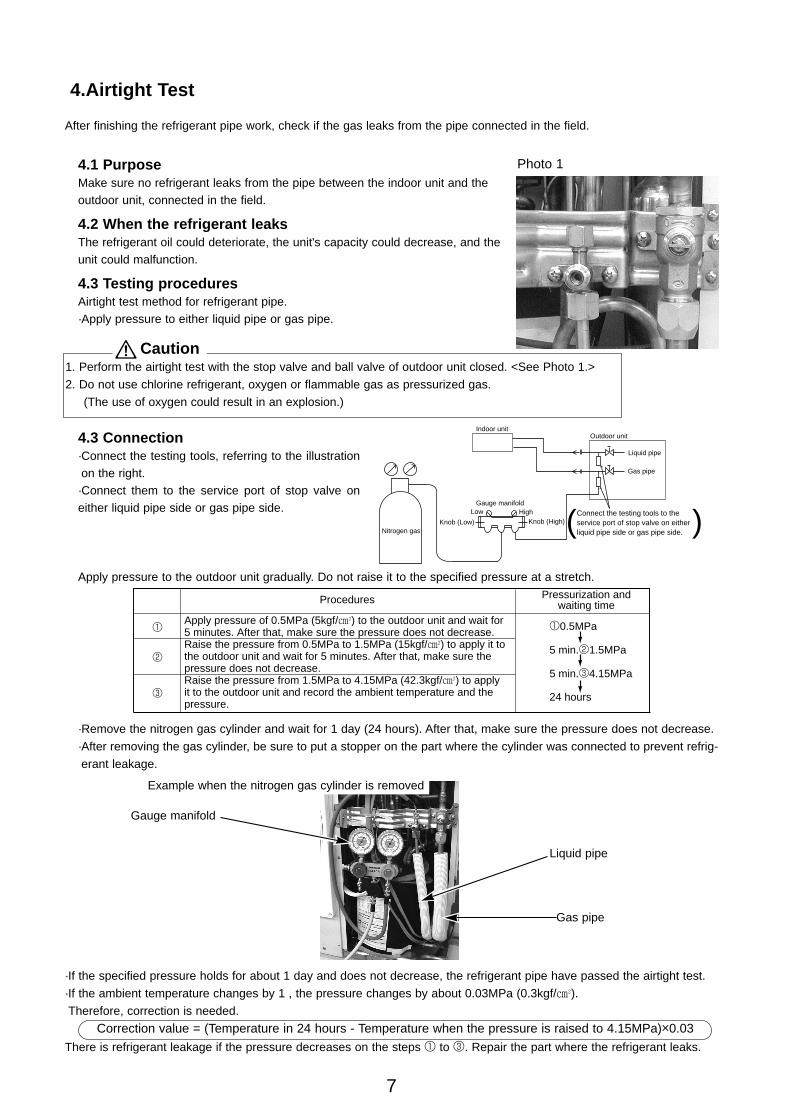
4.3 Connection·Connect the testing tools, referring to the illustrationon the right.·Connect them to the service port of stop valve oneither liquid pipe side or gas pipe side.
Apply pressure to the outdoor unit gradually. Do not raise it to the specified pressure at a stretch.
1. Perform the airtight test with the stop valve and ball valve of outdoor unit closed. <See Photo 1.>
2. Do not use chlorine refrigerant, oxygen or flammable gas as pressurized gas.
(The use of oxygen could result in an explosion.)
7
4.Airtight Test
After finishing the refrigerant pipe work, check if the gas leaks from the pipe connected in the field.
4.1 PurposeMake sure no refrigerant leaks from the pipe between the indoor unit and theoutdoor unit, connected in the field.
4.2 When the refrigerant leaksThe refrigerant oil could deteriorate, the unit's capacity could decrease, and the unit could malfunction.
4.3 Testing proceduresAirtight test method for refrigerant pipe.·Apply pressure to either liquid pipe or gas pipe.
Photo 1
Caution
Low HighGauge manifold
Knob (Low) Knob (High)Connect the testing tools to the service port of stop valve on either liquid pipe side or gas pipe side.
Indoor unit
Gas pipe
Liquid pipe
Outdoor unit
Nitrogen gas ( )
10.5MPa
5 min.21.5MPa
5 min.34.15MPa
24 hours
Apply pressure of 0.5MPa (5kgf/f) to the outdoor unit and wait for 5 minutes. After that, make sure the pressure does not decrease. Raise the pressure from 0.5MPa to 1.5MPa (15kgf/f) to apply it to the outdoor unit and wait for 5 minutes. After that, make sure the pressure does not decrease.Raise the pressure from 1.5MPa to 4.15MPa (42.3kgf/f) to apply it to the outdoor unit and record the ambient temperature and the pressure.
1
2
3
Procedures Pressurization and waiting time
·Remove the nitrogen gas cylinder and wait for 1 day (24 hours). After that, make sure the pressure does not decrease.
·After removing the gas cylinder, be sure to put a stopper on the part where the cylinder was connected to prevent refrig-
erant leakage.
·If the specified pressure holds for about 1 day and does not decrease, the refrigerant pipe have passed the airtight test.
·If the ambient temperature changes by 1 , the pressure changes by about 0.03MPa (0.3kgf/f).
Therefore, correction is needed.
There is refrigerant leakage if the pressure decreases on the steps 1 to 3. Repair the part where the refrigerant leaks.
Correction value = (Temperature in 24 hours - Temperature when the pressure is raised to 4.15MPa)o0.03
Example when the nitrogen gas cylinder is removed
Gauge manifold
Liquid pipe
Gas pipe
Power-Inverter.qxp 04.7.15 5:38 PM Page 7
8
5.Vacuuming (Vacuum Drying)
5.1 Purpose
·Discharge the air in the pipe or nitrogen when the airtight test is performed.
·Perform vacuum drying for the inside of pipe.
5.2 When vacuuming is not performed fully
1 If air goes into the pipe, the high pressure rises abnormally and the compressor could malfunction.
2 If a slight amount of moisture (moisture in the air) goes into the refrigerant cycle, the unit could malfunction.
3 If moisture remains in the refrigerant, the expansion valve could freeze and the unit could malfunction.
· When the atmospheric pressure in the pipe is brought close to a vacuum by the vacuum pump, the boiling point of water
in the pipe lowers.
Lowering the boiling point of water than the outside temperature evaporates water and discharges it outside.
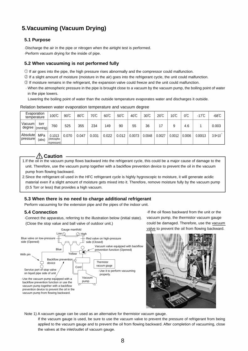
Relation between water evaporation temperature and vacuum degree
Evaporation temperature
760
0.1013
100:
525
0.070
90:
355
0.047
80:
234
0.031
70:
149
0.022
60:
90
0.012
50:
55
0.0073
40:
36
0.0048
30:
17
0.0027
20:
9
0.0012
10:
4.6
0.0006
0:
1
0.00013
0.003
3.9o10
-17: -68:
-7
torr(mmHg)
MPa(abs)
Vacuum degree
Absolute pressure (Atmosphe-
ricpressure)
1.If the oil in the vacuum pump flows backward into the refrigerant cycle, this could be a major cause of damage to theunit. Therefore, use the vacuum pump together with a backflow prevention device to prevent the oil in the vacuumpump from flowing backward.
2.Since the refrigerant oil used in the HFC refrigerant cycle is highly hygroscopic to moisture, it will generate acidicmaterial even if a slight amount of moisture gets mixed into it. Therefore, remove moisture fully by the vacuum pump(0.5 Torr or less) that provides a high vacuum.
Caution
5.3 When there is no need to charge additional refrigerantPerform vacuuming for the extension pipe and the pipes of the indoor unit.
5.4 Connection·Connect the apparatus, referring to the illustration below (initial state).
(Close the stop value and ball valve of outdoor unit.)
Thermistor
Vacuum pump
With pin
Service port of stop valve on liquid pipe side of unit
Low
Blue
Yellow
High
Gauge manifold
Vacuum valve equipped with backflow prevention function (Opened)
Blue valve on low-pressure side (Opened)
Red valve on high-pressure side (Closed)
Backflow preventiondevice
Cord vacuum gauge
· Use the vacuum pump equipped with a backflow prevention function or use the vacuum pump together with a backflow prevention device to prevent the oil in the vacuum pump from flowing backward.
· Use it to perform vacuuming properly.
Note 1) A vacuum gauge can be used as an alternative for thermistor vacuum gauge.If the vacuum gauge is used, be sure to use the vacuum valve to prevent the pressure of refrigerant from beingapplied to the vacuum gauge and to prevent the oil from flowing backward. After completion of vacuuming, closethe valves at the inlet/outlet of vacuum gauge.
·If the oil flows backward from the unit or the
vacuum pump, the thermistor vacuum gauge
could be damaged. Therefore, use the vacuum
valve to prevent the oil from flowing backward.
Power-Inverter.qxp 04.7.15 5:38 PM Page 8
9
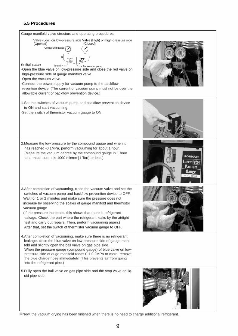
5.5 Procedures
/Now, the vacuum drying has been finished when there is no need to charge additional refrigerant.
Gauge manifold valve structure and operating procedures
(Initial state)·Open the blue valve on low-pressure side and close the red valve onhigh-pressure side of gauge manifold valve.·Open the vacuum valve.·Connect the power supply for vacuum pump to the backflow revention device. (The current of vacuum pump must not be over theallowable current of backflow prevention device.)
1.Set the switches of vacuum pump and backflow prevention deviceto ON and start vacuuming.
·Set the switch of thermistor vacuum gauge to ON.
2.Measure the low pressure by the compound gauge and when it has reached -0.1MPa, perform vacuuming for about 1 hour. (Measure the vacuum degree by the compound gauge in 1 hour and make sure it is 1000 micron [1 Torr] or less.)
3.After completion of vacuuming, close the vacuum valve and set theswitches of vacuum pump and backflow prevention device to OFF.Wait for 1 or 2 minutes and make sure the pressure does not increase by observing the scales of gauge manifold and thermistorvacuum gauge.(If the pressure increases, this shows that there is refrigerant eakage. Check the part where the refrigerant leaks by the airtighttest and carry out repairs. Then, perform vacuuming again.)After that, set the switch of thermistor vacuum gauge to OFF.
4.After completion of vacuuming, make sure there is no refrigerantleakage, close the blue valve on low-pressure side of gauge mani-fold and slightly open the ball valve on gas pipe side. When the pressure gauge (compound gauge) of blue valve on low-pressure side of auge manifold reads 0.1-0.2MPa or more, removethe blue charge hose immediately. (This prevents air from goinginto the refrigerant pipe.)
5.Fully open the ball valve on gas pipe side and the stop valve on liq-uid pipe side.
Low High
Valve (Low) on low-pressure side Valve (High) on high-pressure side
To unit To vacuum pump
Compound gauge
(Opened) (Closed)
Power-Inverter.qxp 04.7.15 5:38 PM Page 9
10
6.Checking the Gas Leakage
6.1 Purpose
It is important to pay attention to gas leakage since R410A has smaller constituent element and higher pressure
compared to the conventional refrigerant.
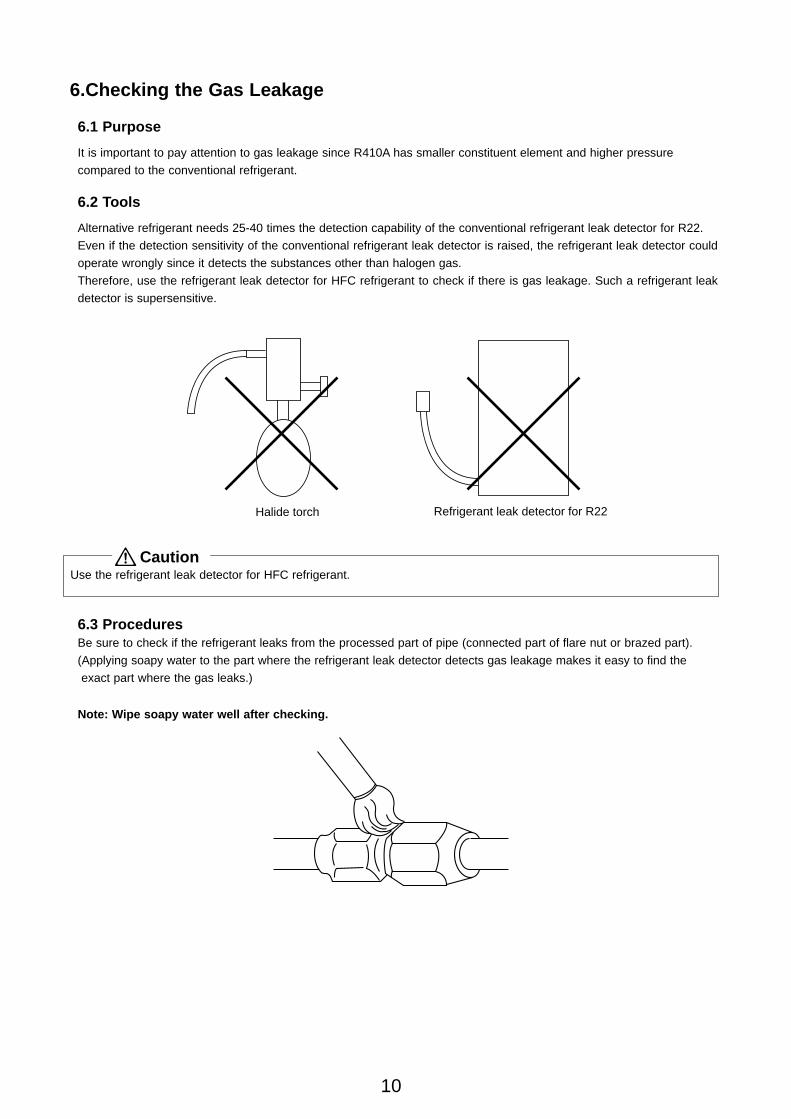
6.2 Tools
Alternative refrigerant needs 25-40 times the detection capability of the conventional refrigerant leak detector for R22.
Even if the detection sensitivity of the conventional refrigerant leak detector is raised, the refrigerant leak detector could
operate wrongly since it detects the substances other than halogen gas.
Therefore, use the refrigerant leak detector for HFC refrigerant to check if there is gas leakage. Such a refrigerant leak
detector is supersensitive.
Halide torch Refrigerant leak detector for R22
Use the refrigerant leak detector for HFC refrigerant.Caution
6.3 ProceduresBe sure to check if the refrigerant leaks from the processed part of pipe (connected part of flare nut or brazed part).
(Applying soapy water to the part where the refrigerant leak detector detects gas leakage makes it easy to find the
exact part where the gas leaks.)
Note: Wipe soapy water well after checking.
Power-Inverter.qxp 04.7.15 5:38 PM Page 10
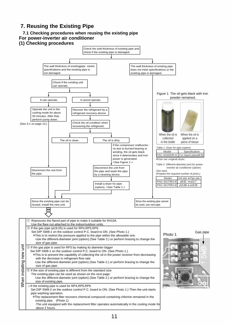
Check the wall thickness of existing pipe and check if the existing pipe is damaged.
Check if the existing unit can operate.
Recover the refrigerant by a refrigerant recovery device.
Check the oil condition when recovering the refrigerant.
Operate the unit in the cooling mode for about 30 minutes. After that, perform pump down.
Since the existing pipe can be reused, install the new unit.
Since the existing pipe cannot be used, use new pipe.
Disconnect the unit from the pipe and wash the pipe by a cleaning device.
Install a dryer for pipe (option). <See Table 1.>
The oil is dirty.The oil is clean.
It can operate.
(See 3-1 on page 13.)
It cannot operate.
The wall thickness of existing pipe does not meet specifications or the existing pipe is damaged.
The wall thickness of existingpipe meetsspecifications and the existing pipe isnot damaged.
If the compressor malfunctio-ns due to burned bearing or winding, the oil gets black since it deteriorates and iron power is generated. <See Figure 1.>
Disconnect the unit from the pipe.
Table 1 Dryer for pipe (option)
wUse our original dryer.
ModelPAC-SG82DR-E
SpecificationFor liquid pipe{9.52
Table 2 Different-diameter joint for power- inverter air conditioner (option)One each (Prepare the required number of joints.)
ModelPAC-SG73RJ-EPAC-SG75RJ-E
Unit side ➔ Pipe side{9.52 ➔ {12.7{15.88 ➔ {19.05
11
7. Reusing the Existing Pipe7.1 Checking procedures when reusing the existing pipe
For power-inverter air conditioner(1) Checking procedures
When the oil is applied on a
piece of tissue
When the oil is collected
in the bottle
Figure 1 The oil gets black with iron powder remained.
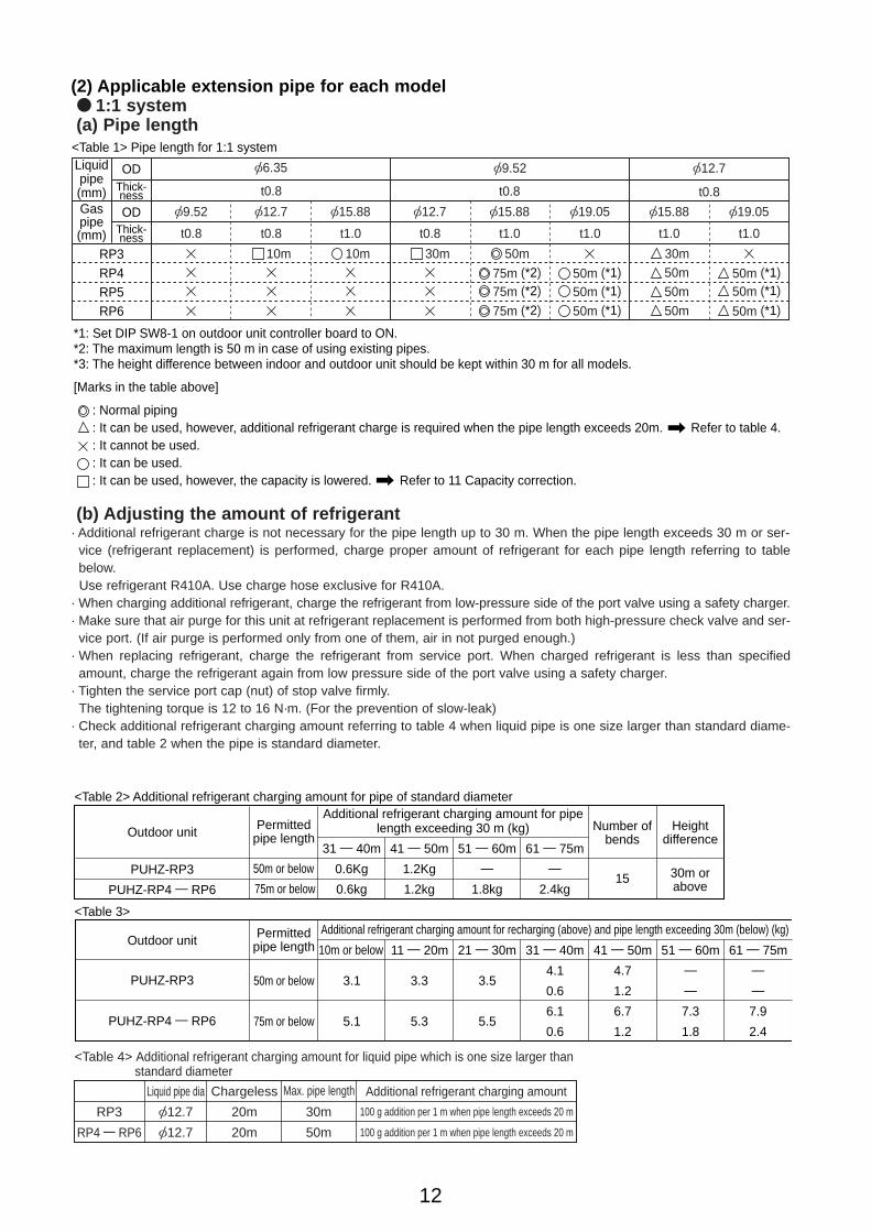
1 Reprocess the flared part of pipe to make it suitable for R410A. Use the flare nut attached to the indoor/outdoor units.2 If the gas pipe ({19.05) is used for RP4,RP5,RP6 Set DIP SW8-1 on the outdoor control P.C. board to ON. (See Photo 1.) wThis is to restrict the pressure applied to the pipe within the allowable one. ·Use the different-diameter joint (option) (See Table 2.) or perform brazing to change the size of gas pipe.
3 If the gas pipe is used for RP3 by making its diameter bigger Set DIP SW8-1 on the outdoor control P.C. board to ON. (See Photo 1.) wThis is to prevent the capability of collecting the oil in the power receiver from decreasing with the decrease in refrigerant flow rate. ·Use the different-diameter joint (option) (See Table 2.) or perform brazing to change the size of gas pipe.
4 If the size of existing pipe is different from the standard size The existing pipe can be used as shown on the next page. ·Use the different-diameter joint (option) (See Table 2.) or perform brazing to change the size of existing pipe.
If the existing pipe is used for RP4,RP5,RP6 Set DIP SW8-2 on the outdoor control P.C. board to ON. (See Photo 1.) Then the unit starts pipe washing operation. wThe replacement filter recovers chemical compound containing chlorine remained in the existing pipe. (Photo 1) ·The unit equipped with the replacement filter operates automatically in the cooling mode for about 2 hours.
Photo 1Gas pipe
Power-Inverter.qxp 04.7.15 5:38 PM Page 11
12
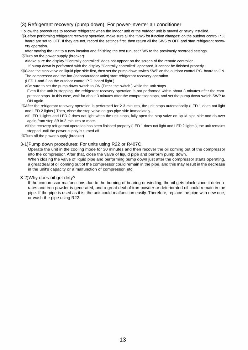
(2) Applicable extension pipe for each model● 1:1 system(a) Pipe length
Liquid pipe(mm)Gas pipe(mm)
[6.35 [9.52 [12.7
[9.52
ODThick-ness
ODThick-ness
RP3RP4RP5RP6
t0.8
t0.8
[12.7
t0.8
[15.88
t1.0
[12.7
t0.8
[15.88
t1.0
[19.05
t1.0
[15.88
t1.0
[19.05
t1.0
t0.8 t0.8
: Normal piping: It can be used, however, additional refrigerant charge is required when the pipe length exceeds 20m. Refer to table 4.: It cannot be used.: It can be used.: It can be used, however, the capacity is lowered. Refer to 11 Capacity correction.
<Table 1> Pipe length for 1:1 system
*1: Set DIP SW8-1 on outdoor unit controller board to ON.*2: The maximum length is 50 m in case of using existing pipes.*3: The height difference between indoor and outdoor unit should be kept within 30 m for all models.
[Marks in the table above]
10m 30m 30m50m50m
50m
10m
50m (*1)75m (*2)50m
75m (*2)
75m (*2)
50m (*1)50m (*1)
50m (*1)50m (*1)
50m (*1)
(b) Adjusting the amount of refrigerant· Additional refrigerant charge is not necessary for the pipe length up to 30 m. When the pipe length exceeds 30 m or ser-
vice (refrigerant replacement) is performed, charge proper amount of refrigerant for each pipe length referring to tablebelow.Use refrigerant R410A. Use charge hose exclusive for R410A.
· When charging additional refrigerant, charge the refrigerant from low-pressure side of the port valve using a safety charger.· Make sure that air purge for this unit at refrigerant replacement is performed from both high-pressure check valve and ser-
vice port. (If air purge is performed only from one of them, air in not purged enough.)· When replacing refrigerant, charge the refrigerant from service port. When charged refrigerant is less than specified
amount, charge the refrigerant again from low pressure side of the port valve using a safety charger.· Tighten the service port cap (nut) of stop valve firmly.
The tightening torque is 12 to 16 N·m. (For the prevention of slow-leak)· Check additional refrigerant charging amount referring to table 4 when liquid pipe is one size larger than standard diame-
ter, and table 2 when the pipe is standard diameter.
15 30m orabove
31 — 40m
0.6Kg
0.6kg
10m or below
41 — 50m
1.2Kg
1.2kg
51 — 60m
—
1.8kg
61 — 75m
—
2.4kg
<Table 2> Additional refrigerant charging amount for pipe of standard diameter
<Table 3>
Outdoor unit Permittedpipe length
Additional refrigerant charging amount for pipelength exceeding 30 m (kg)
PUHZ-RP3
PUHZ-RP4 — RP6
Outdoor unit
PUHZ-RP3
PUHZ-RP4 — RP6
Number ofbends
Heightdifference
50m or below
75m or below
Permitted pipe length
50m or below
75m or below
3.1
5.1
11 — 20m 21 — 30m
3.3
5.3
3.5
5.5
31 — 40m
4.1
0.6
6.1
0.6
4.7
1.2
6.7
1.2
—
—
7.3
1.8
—
—
7.9
2.4
41 — 50m 51 — 60m 61 — 75m
Additional refrigerant charging amount for recharging (above) and pipe length exceeding 30m (below) (kg)
<Table 4> Additional refrigerant charging amount for liquid pipe which is one size larger than standard diameter
[12.7
[12.7
RP3
RP4 — RP6
Liquid pipe dia Chargeless
30m
50m
100 g addition per 1 m when pipe length exceeds 20 m
100 g addition per 1 m when pipe length exceeds 20 m
20m
20m
Max. pipe length Additional refrigerant charging amount
Power-Inverter.qxp 04.7.15 5:38 PM Page 12
13
(3) Refrigerant recovery (pump down): For power-inverter air conditioner·Follow the procedures to recover refrigerant when the indoor unit or the outdoor unit is moved or newly installed.1Before performing refrigerant recovery operation, make sure all the "SW5 for function changes" on the outdoor control P.C.
board are set to OFF. If they are not, record the settings first, then return all the SW5 to OFF and start refrigerant recov-ery operation. After moving the unit to a new location and finishing the test run, set SW5 to the previously recorded settings.
2Turn on the power supply (breaker).wMake sure the display "Centrally controlled" does not appear on the screen of the remote controller.
If pump down is performed with the display "Centrally controlled" appeared, it cannot be finished properly. 3Close the stop valve on liquid pipe side first, then set the pump down switch SWP on the outdoor control P.C. board to ON.
The compressor and the fan (indoor/outdoor units) start refrigerant recovery operation. (LED 1 and 2 on the outdoor control P.C. board light.)wBe sure to set the pump down switch to ON (Press the switch.) while the unit stops.
Even if the unit is stopping, the refrigerant recovery operation is not performed within about 3 minutes after the com-pressor stops. In this case, wait for about 3 minutes after the compressor stops, and set the pump down switch SWP toON again.
4After the refrigerant recovery operation is performed for 2-3 minutes, the unit stops automatically (LED 1 does not lightand LED 2 lights.) Then, close the stop valve on gas pipe side immediately.wIf LED 1 lights and LED 2 does not light when the unit stops, fully open the stop valve on liquid pipe side and do over
again from step áB in 3 minutes or more.wIf the recovery refrigerant operation has been finished properly (LED 1 does not light and LED 2 lights.), the unit remains
stopped until the power supply is turned off.5Turn off the power supply (breaker).
3-1)Pump down procedures: For units using R22 or R407COperate the unit in the cooling mode for 30 minutes and then recover the oil coming out of the compressorinto the compressor. After that, close the valve of liquid pipe and perform pump down. When closing the valve of liquid pipe and performing pump down just after the compressor starts operating,a great deal of oil coming out of the compressor could remain in the pipe, and this may result in the decreasein the unit's capacity or a malfunction of compressor, etc.
3-2)Why does oil get dirty?If the compressor malfunctions due to the burning of bearing or winding, the oil gets black since it deterio-rates and iron powder is generated, and a great deal of iron powder or deteriorated oil could remain in thepipe. If the pipe is used as it is, the unit could malfunction easily. Therefore, replace the pipe with new one,or wash the pipe using R22.
Power-Inverter.qxp 04.7.15 5:38 PM Page 13
14
7.2 Reprocessing of pipe end and Operation when reusing the existing pipe
When reusing the existing pipe, reprocess the flared part of pipe to make it suitable for R410A. Moreover, replace the flarenut with one attached to the unit.
(1) Power-inverter operation
1There is no need for this operation if new pipe is used.2As for RP3, there is no need for this operation even if the existing pipe for R22 is used.
(The power-inverter operation cannot be performed.)
·Procedures for power-inverter operation1Turn on the power supply.2Set SW8-3 on the outdoor control P.C. board to ON to start power-inverter operation.
·Since the power-inverter operation is performed in the cooling mode, the indoor unit blows out cool air during this oper-ation.·During the power-inverter operation, LED 1 and 2 on the outdoor control P.C. board blink at the same time with thedisplay "Test run" appeared on the screen of the remote controller.
3Be sure to perform the power-inverter operation for 2 hours or more.·The unit stops power-inverter operation automatically 2hours after setting SW8-2 to ON.·Since the power-inverter operation can be repeated by changing the setting of SW8-2 from OFF to ON, be sure toperform the operation for 2 hours or more. (If the operation time is less than 2 hours, the unit could be damaged sincethe existing pipe is not washed fully.)
4Set SW8-2 to OFF. (Now, the power-inverter operation has been finished.)wThe compressor may operate continuously at the room temperature less than 15:, however, this is not a alfunction of unit.
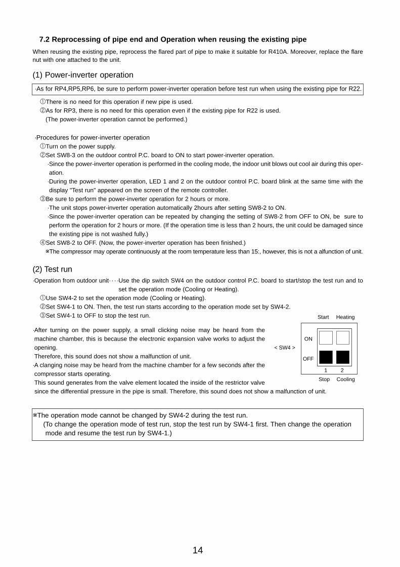
(2) Test run·Operation from outdoor unit· · · ·Use the dip switch SW4 on the outdoor control P.C. board to start/stop the test run and to
set the operation mode (Cooling or Heating).1Use SW4-2 to set the operation mode (Cooling or Heating).2Set SW4-1 to ON. Then, the test run starts according to the operation mode set by SW4-2.3Set SW4-1 to OFF to stop the test run.
·After turning on the power supply, a small clicking noise may be heard from themachine chamber, this is because the electronic expansion valve works to adjust theopening.Therefore, this sound does not show a malfunction of unit.
·A clanging noise may be heard from the machine chamber for a few seconds after thecompressor starts operating. This sound generates from the valve element located the inside of the restrictor valvesince the differential pressure in the pipe is small. Therefore, this sound does not show a malfunction of unit.
·As for RP4,RP5,RP6, be sure to perform power-inverter operation before test run when using the existing pipe for R22.
< SW4 >
Heating
Cooling
1 2
ON
OFF
Start
Stop
wThe operation mode cannot be changed by SW4-2 during the test run.(To change the operation mode of test run, stop the test run by SW4-1 first. Then change the operationmode and resume the test run by SW4-1.)
Power-Inverter.qxp 04.7.15 5:38 PM Page 14
1/4"
3/8"
1/2"
5/8"
5/8"3/4"
6.35
9.52
12.7
15.88
15.8819.05
R22
17
22
24
27
36
R410A
17
22
26
29
3636
18N · m(180kgf · cm)
42N · m(420kgf · cm)
55N · m(550kgf · cm)
75N · m(750kgf · cm)
100N · m(1000kgf · cm)
100N · m(1000kgf · cm)
Nominal diameter
TorqueOutside diameter
Dimension "B"
[mm]
15
8. Tools for Installation
8.1 Necessary tools
(1) For R410A
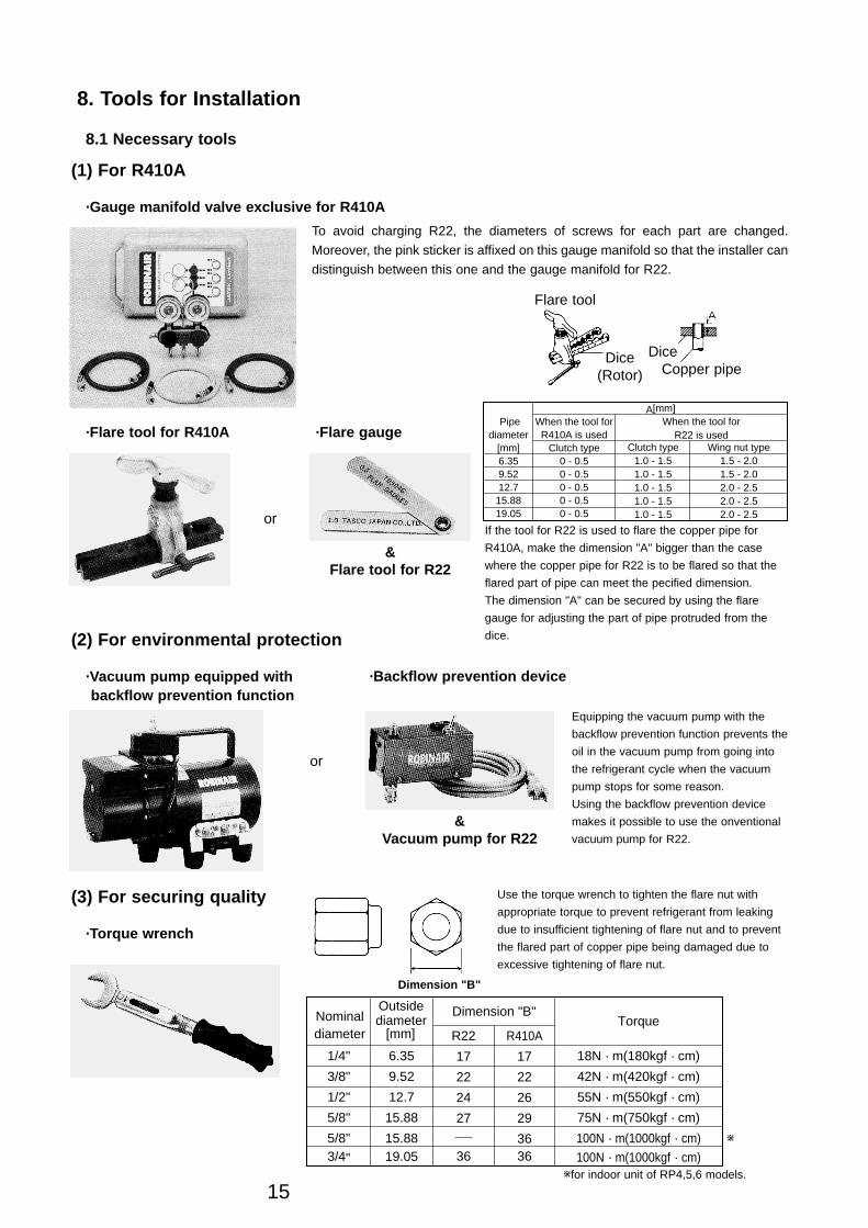
·Gauge manifold valve exclusive for R410A
To avoid charging R22, the diameters of screws for each part are changed.
Moreover, the pink sticker is affixed on this gauge manifold so that the installer can
distinguish between this one and the gauge manifold for R22.
Flare tool
Dice(Rotor)
DiceCopper pipe
·Flare tool for R410A ·Flare gauge
or
&Flare tool for R22
Pipe diameter
[mm]6.359.5212.7
15.8819.05
When the tool for R410A is used
Clutch type0 - 0.50 - 0.50 - 0.50 - 0.50 - 0.5
Clutch type1.0 - 1.51.0 - 1.51.0 - 1.51.0 - 1.51.0 - 1.5
Wing nut type1.5 - 2.01.5 - 2.02.0 - 2.52.0 - 2.52.0 - 2.5
When the tool for R22 is used
A[mm]
If the tool for R22 is used to flare the copper pipe for
R410A, make the dimension "A" bigger than the case
where the copper pipe for R22 is to be flared so that the
flared part of pipe can meet the pecified dimension.
The dimension "A" can be secured by using the flare
gauge for adjusting the part of pipe protruded from the
dice.(2) For environmental protection
·Vacuum pump equipped with backflow prevention function
·Backflow prevention device
or
&Vacuum pump for R22
Equipping the vacuum pump with the
backflow prevention function prevents the
oil in the vacuum pump from going into
the refrigerant cycle when the vacuum
pump stops for some reason.
Using the backflow prevention device
makes it possible to use the onventional
vacuum pump for R22.
(3) For securing quality
·Torque wrench
Dimension "B"
w
wfor indoor unit of RP4,5,6 models.
Use the torque wrench to tighten the flare nut with
appropriate torque to prevent refrigerant from leaking
due to insufficient tightening of flare nut and to prevent
the flared part of copper pipe being damaged due to
excessive tightening of flare nut.
Power-Inverter.qxp 04.7.15 5:38 PM Page 15
16
8.2 Convenient tools
(1) For securing quality
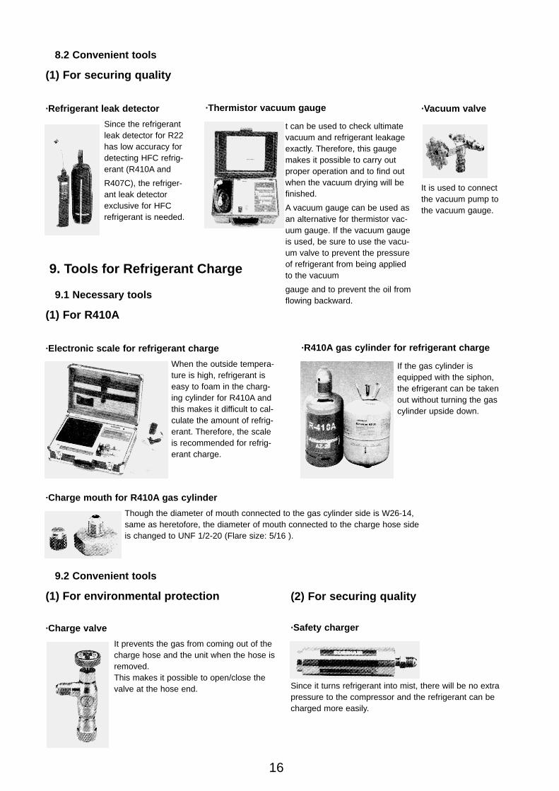
·Refrigerant leak detector
Since the refrigerantleak detector for R22has low accuracy fordetecting HFC refrig-erant (R410A and
R407C), the refriger-ant leak detectorexclusive for HFCrefrigerant is needed.
t can be used to check ultimatevacuum and refrigerant leakageexactly. Therefore, this gaugemakes it possible to carry outproper operation and to find outwhen the vacuum drying will befinished.
A vacuum gauge can be used asan alternative for thermistor vac-uum gauge. If the vacuum gaugeis used, be sure to use the vacu-um valve to prevent the pressureof refrigerant from being appliedto the vacuum
gauge and to prevent the oil fromflowing backward.
·Thermistor vacuum gauge ·Vacuum valve
It is used to connectthe vacuum pump tothe vacuum gauge.
9.1 Necessary tools
(1) For R410A
·Electronic scale for refrigerant charge
When the outside tempera-ture is high, refrigerant iseasy to foam in the charg-ing cylinder for R410A andthis makes it difficult to cal-culate the amount of refrig-erant. Therefore, the scaleis recommended for refrig-erant charge.
If the gas cylinder isequipped with the siphon,the efrigerant can be takenout without turning the gascylinder upside down.
·R410A gas cylinder for refrigerant charge
9. Tools for Refrigerant Charge
·Charge mouth for R410A gas cylinder
Though the diameter of mouth connected to the gas cylinder side is W26-14,same as heretofore, the diameter of mouth connected to the charge hose sideis changed to UNF 1/2-20 (Flare size: 5/16 ).
9.2 Convenient tools
(1) For environmental protection
·Charge valve
It prevents the gas from coming out of thecharge hose and the unit when the hose isremoved.This makes it possible to open/close thevalve at the hose end. Since it turns refrigerant into mist, there will be no extra
pressure to the compressor and the refrigerant can becharged more easily.
·Safety charger
(2) For securing quality
Power-Inverter.qxp 04.7.15 5:38 PM Page 16
17
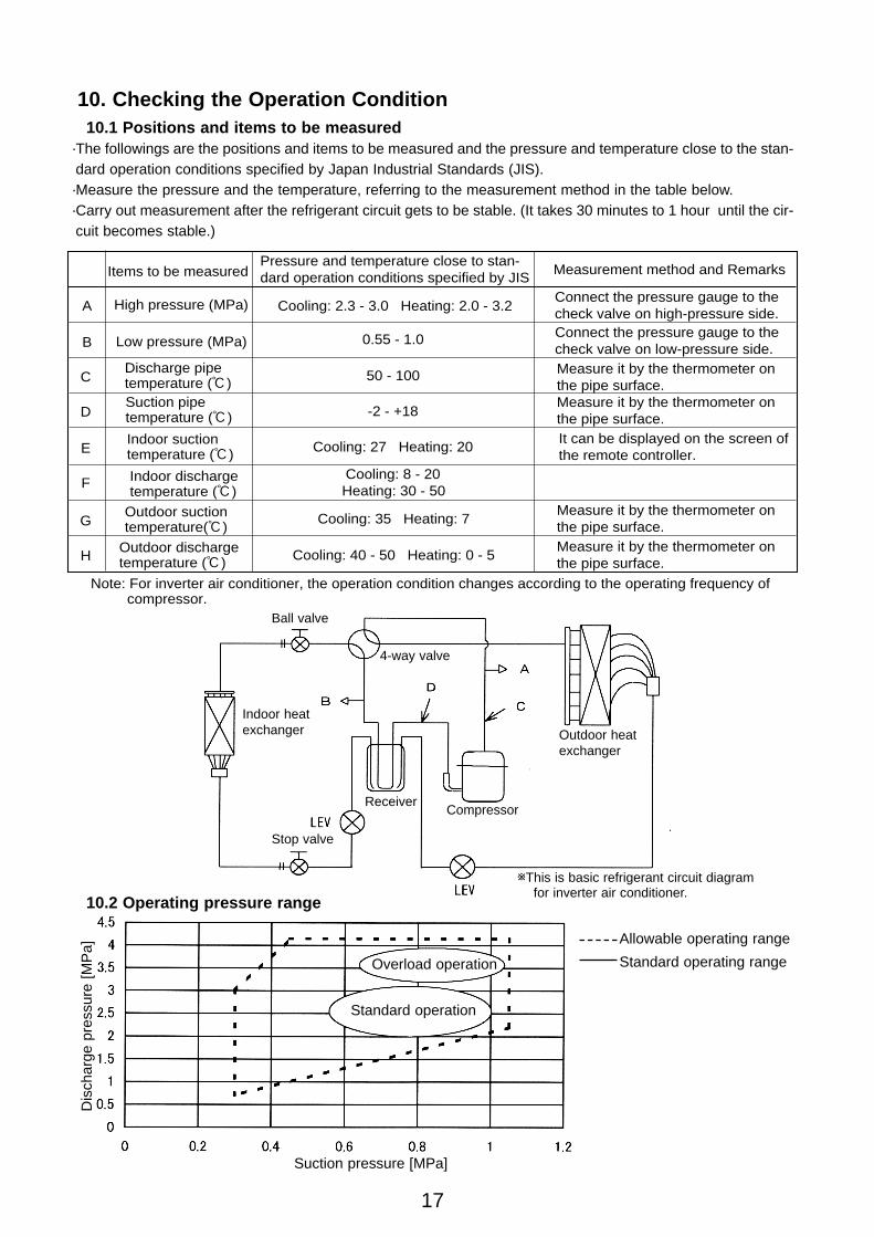
10. Checking the Operation Condition10.1 Positions and items to be measured
·The followings are the positions and items to be measured and the pressure and temperature close to the stan-dard operation conditions specified by Japan Industrial Standards (JIS).·Measure the pressure and the temperature, referring to the measurement method in the table below.·Carry out measurement after the refrigerant circuit gets to be stable. (It takes 30 minutes to 1 hour until the cir-cuit becomes stable.)
Items to be measured
0.55 - 1.0
Pressure and temperature close to stan-dard operation conditions specified by JIS
Measurement method and Remarks
A
Note: For inverter air conditioner, the operation condition changes according to the operating frequency of compressor.
High pressure (MPa)
Discharge pipetemperature (:)Suction pipetemperature (:)
Indoor suctiontemperature (:)
C
D
E
F
G
H
Indoor dischargetemperature (:)
Outdoor suctiontemperature(:)
Outdoor dischargetemperature (:)
50 - 100
-2 - +18
Cooling: 27 Heating: 20
Cooling: 8 - 20Heating: 30 - 50
Cooling: 35 Heating: 7
Cooling: 40 - 50 Heating: 0 - 5
B Low pressure (MPa)
Cooling: 2.3 - 3.0 Heating: 2.0 - 3.2Connect the pressure gauge to thecheck valve on high-pressure side.Connect the pressure gauge to thecheck valve on low-pressure side.Measure it by the thermometer onthe pipe surface.Measure it by the thermometer onthe pipe surface.It can be displayed on the screen of the remote controller.
Measure it by the thermometer onthe pipe surface.Measure it by the thermometer onthe pipe surface.
wThis is basic refrigerant circuit diagram for inverter air conditioner.
Ball valve
Indoor heatexchanger
Stop valve
Compressor
4-way valve
Outdoor heatexchanger
Receiver
10.2 Operating pressure range
Dis
char
ge p
ress
ure
[MP
a]
Suction pressure [MPa]
Standard operating range
Allowable operating range
Standard operation
Overload operation
Power-Inverter.qxp 04.7.15 5:38 PM Page 17
18
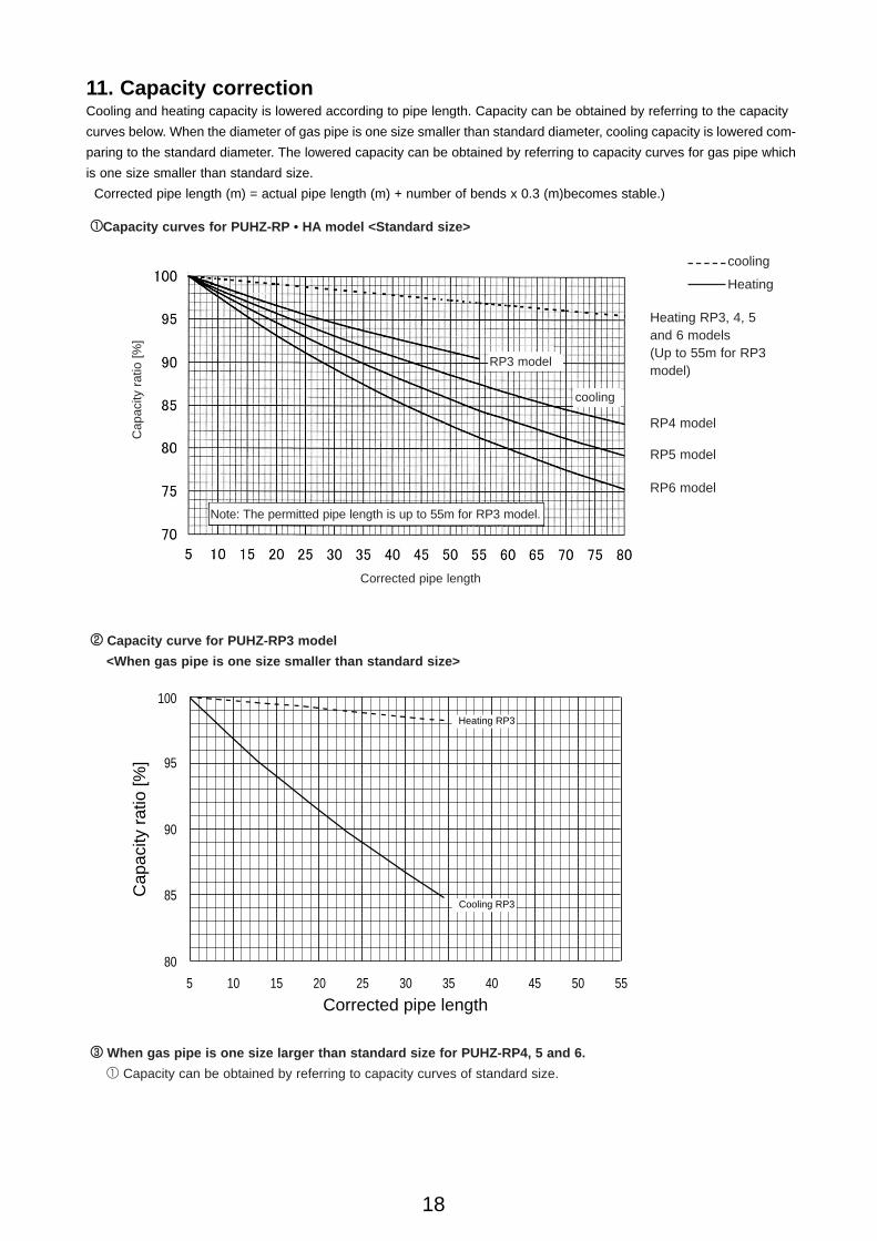
11. Capacity correctionCooling and heating capacity is lowered according to pipe length. Capacity can be obtained by referring to the capacity
curves below. When the diameter of gas pipe is one size smaller than standard diameter, cooling capacity is lowered com-
paring to the standard diameter. The lowered capacity can be obtained by referring to capacity curves for gas pipe which
is one size smaller than standard size.
Corrected pipe length (m) = actual pipe length (m) + number of bends x 0.3 (m)becomes stable.)
11Capacity curves for PUHZ-RP • HA model <Standard size>
Cap
acity
rat
io [
%]
Note: The permitted pipe length is up to 55m for RP3 model.
Heating
cooling
Corrected pipe length
RP3 model
RP5 model
RP4 model
cooling
RP6 model
Heating RP3, 4, 5and 6 models(Up to 55m for RP3model)
22 Capacity curve for PUHZ-RP3 model
<When gas pipe is one size smaller than standard size>
5 10 15 20 25 30 35 40 45 50 55
80
Cap
acity
rat
io [%
]
Corrected pipe length
85
90
95
100
Heating RP3
Cooling RP3
33 When gas pipe is one size larger than standard size for PUHZ-RP4, 5 and 6.
1 Capacity can be obtained by referring to capacity curves of standard size.
Power-Inverter.qxp 04.7.15 5:38 PM Page 18
19
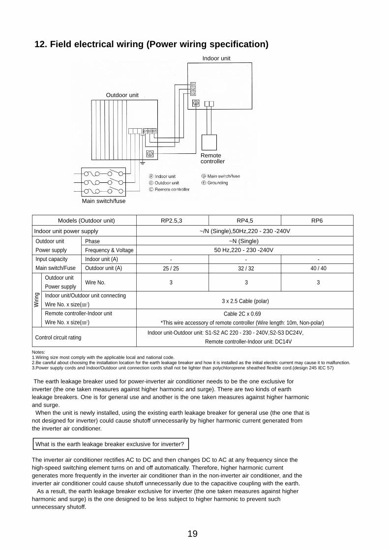
12. Field electrical wiring (Power wiring specification)
Remotecontroller
Indoor unit
Main switch/fuse
Phase
Frequency & Voltage
Indoor unit (A)
Outdoor unit (A)
Models (Outdoor unit)
Indoor unit power supply
Outdoor unit
Power supply
Input capacity
Main switch/Fuse
Outdoor unit
Power supply
Indoor unit/Outdoor unit connecting
Wire No. x size(e)
Remote controller-Indoor unit
Wire No. x size(e)
Control circuit rating
RP2.5,3 RP4,5 RP6
~/N (Single),50Hz,220 - 230 -240V
~N (Single)
50 Hz,220 - 230 -240V
-
25 / 25
-
32 / 32
-
40 / 40
3 3 3Wire No.
3 x 2.5 Cable (polar)
Cable 2C x 0.69
*This wire accessory of remote controller (Wire length: 10m, Non-polar)
Indoor unit-Outdoor unit: S1-S2 AC 220 - 230 - 240V,S2-S3 DC24V,
Remote controller-Indoor unit: DC14V
Notes:1.Wiring size most comply with the applicable local and national code.2.Be careful about choosing the installation location for the earth leakage breaker and how it is installed as the initial electric current may cause it to malfunction.3.Power supply cords and Indoor/Outdoor unit connection cords shall not be lighter than polychloroprene sheathed flexible cord.(design 245 IEC 57)
The earth leakage breaker used for power-inverter air conditioner needs to be the one exclusive for inverter (the one taken measures against higher harmonic and surge). There are two kinds of earth leakage breakers. One is for general use and another is the one taken measures against higher harmonic and surge.
When the unit is newly installed, using the existing earth leakage breaker for general use (the one that is not designed for inverter) could cause shutoff unnecessarily by higher harmonic current generated from the inverter air conditioner.
What is the earth leakage breaker exclusive for inverter?
The inverter air conditioner rectifies AC to DC and then changes DC to AC at any frequency since the high-speed switching element turns on and off automatically. Therefore, higher harmonic current generates more frequently in the inverter air conditioner than in the non-inverter air conditioner, and the inverter air conditioner could cause shutoff unnecessarily due to the capacitive coupling with the earth.
As a result, the earth leakage breaker exclusive for inverter (the one taken measures against higher harmonic and surge) is the one designed to be less subject to higher harmonic to prevent such unnecessary shutoff.
Outdoor unit
Power-Inverter.qxp 04.7.15 5:38 PM Page 19
20
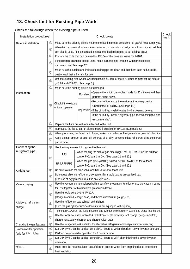
13. Check List for Existing Pipe Work
Make sure the existing pipe is not the one used in the air conditioner of gas/oil heat pump type.
When two or three indoor units are connected to one outdoor unit, check if our original distribu-
tion pipe is used. (If it is not used, change the distribution pipe to our original one.)
Prepare the tools that can be used for R410A or the ones exclusive for R410A.
If the different-diameter pipe is used, make sure the pipe length is within the specified
maximum one.(See page 12.)
Make sure the outside and inside of existing pipe are clean and that there is no sulfur, oxide,
dust or warf that is harmful for use.
Use the existing pipe whose wall thickness is t0.8mm or more (t1.0mm or more for the pipe of
{15.88 and {19.05). (See page 5.)
Make sure the existing pipe is not damaged.
Installation procedures
Check the followings when the existing pipe is used.
Before installation
Installation
2
1
1Check if the existingunit can operate.
RP3
RP4,RP5,RP6
Possible
Impossible
Check pointsCheckmark
3
1
4
5
6
7
2 Replace the flare nut with one attached to the unit.
Reprocess the flared part of pipe to make it suitable for R410A. (See page 5.)
When processing the flared part of pipe, make sure no burr or foreign material goes into the pipe.
Apply a small amount of ester oil, ethereal oil or alkyl benzene oil as refrigerant oil to the flared
part of pipe.
3
4
5
· Operate the unit in the cooling mode for 30 minutes and then
perform pump down.
· Recover refrigerant by the refrigerant recovery device.
· Check if the oil is dirty. (See page 11.)
· If the oil is dirty, wash the pipe by the cleaning device.
· If the oil is dirty, install a dryer for pipe after washing the pipe
(recommended).
Connecting therefrigerant pipe
Use the torque wrench to tighten the flare nut.1
· When making the size of gas pipe bigger, set DIP SW8-1 on the outdoor
control P.C. board to ON. (See page 11 and 12.)
· When the gas pipe ({19.05) is used, set DIP SW8-1 on the outdoor
control P.C. board to ON. (See page 11 and 12.)
Airtight test
2
Be sure to close the stop valve and ball valve of outdoor unit.
Do not use chlorine refrigerant, oxygen or flammable gas as pressurized gas.
(The use of oxygen could result in an explosion.)
Use the vacuum pump equipped with a backflow prevention function or use the vacuum pump
for R22 together with a backflow prevention device.
Use the tools exclusive for R410A.
(Gauge manifold, charge hose, and thermistor vacuum gauge, etc.)
Use the refrigerant gas cylinder with siphon.
(Turn the gas cylinder upside down if it is not equipped with siphon.)
Take out R410A from the liquid phase of gas cylinder and charge R410A of gas phase into the unit.
Use the tools exclusive for R410A. (Electronic scale for refrigerant charge, gauge manifold,
charge hose,safety charger, and charge valve, etc.)
Use the refrigerant leak detector for alternative refrigerant and soapy water for checking.
Set DIP SW8-2 on the outdoor control P.C. board to ON and perform power-inverter operation.
Perform power-inverter operation for 2 hours or more.
Set DIP SW8-2 on the outdoor control P.C. board to OFF after finishing the power-inverter
operation.
Make sure the heat insulation is sufficient to prevent water from dropping due to insufficient
heat insulation.
2
Vacuum drying1
2
Additional refrigerant
charge1
2
3
Checking the gas leakage
Power-inverter operation
(only for RP4 - RP6)
1
1
2
3
Others1
Power-Inverter.qxp 04.7.15 5:38 PM Page 20

21
Power-Inverter.qxp 04.7.15 5:38 PM Page 21

22
Power-Inverter.qxp 04.7.15 5:38 PM Page 22

23
Power-Inverter.qxp 04.7.15 5:38 PM Page 23

Issued in 2003 For R410A
Construction Manual for Power-Inverter Air Conditioner
Power-Inverter.qxp 04.7.15 5:38 PM Page 24