Embed Size (px)
Citation preview
- 0 -
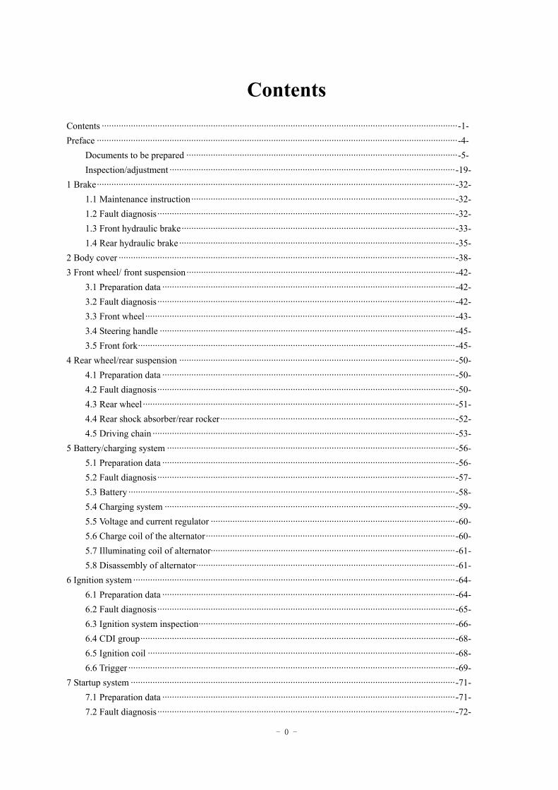
Contents Contents ···················································································································································-1- Preface ·····················································································································································-4-
Documents to be prepared ················································································································-5- Inspection/adjustment ······················································································································-19-
1 Brake····················································································································································-32- 1.1 Maintenance instruction·············································································································-32- 1.2 Fault diagnosis···························································································································-32- 1.3 Front hydraulic brake·················································································································-33- 1.4 Rear hydraulic brake ··················································································································-35-
2 Body cover ···········································································································································-38- 3 Front wheel/ front suspension···············································································································-42-
3.1 Preparation data ·························································································································-42- 3.2 Fault diagnosis···························································································································-42- 3.3 Front wheel································································································································-43- 3.4 Steering handle ··························································································································-45- 3.5 Front fork···································································································································-45-
4 Rear wheel/rear suspension ··················································································································-50- 4.1 Preparation data ·························································································································-50- 4.2 Fault diagnosis···························································································································-50- 4.3 Rear wheel ·································································································································-51- 4.4 Rear shock absorber/rear rocker·································································································-52- 4.5 Driving chain ·····························································································································-53-
5 Battery/charging system ·······················································································································-56- 5.1 Preparation data ·························································································································-56- 5.2 Fault diagnosis···························································································································-57- 5.3 Battery ·······································································································································-58- 5.4 Charging system ························································································································-59- 5.5 Voltage and current regulator ·····································································································-60- 5.6 Charge coil of the alternator·······································································································-60- 5.7 Illuminating coil of alternator·····································································································-61- 5.8 Disassembly of alternator···········································································································-61-
6 Ignition system ·····································································································································-64- 6.1 Preparation data ·························································································································-64- 6.2 Fault diagnosis···························································································································-65- 6.3 Ignition system inspection··········································································································-66- 6.4 CDI group··································································································································-68- 6.5 Ignition coil ·······························································································································-68- 6.6 Trigger ·······································································································································-69-
7 Startup system ······································································································································-71- 7.1 Preparation data ·························································································································-71- 7.2 Fault diagnosis···························································································································-72-
- 1 -
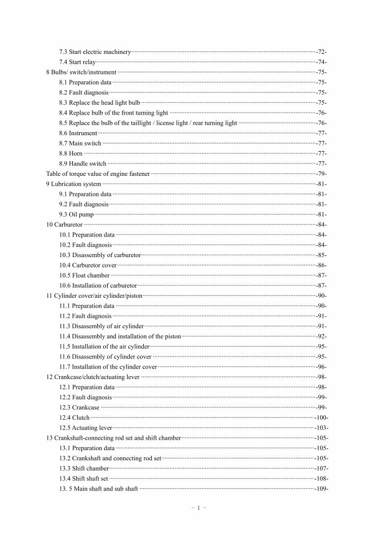
7.3 Start electric machinery··············································································································-72- 7.4 Start relay···································································································································-74-
8 Bulbs/ switch/instrument ······················································································································-75- 8.1 Preparation data ·························································································································-75- 8.2 Fault diagnosis···························································································································-75- 8.3 Replace the head light bulb ········································································································-75- 8.4 Replace bulb of the front turning light ·······················································································-76- 8.5 Replace the bulb of the taillight / license light / rear turning light ··············································-76- 8.6 Instrument··································································································································-77- 8.7 Main switch ·······························································································································-77- 8.8 Horn ··········································································································································-77- 8.9 Handle switch ····························································································································-77-
Table of torque value of engine fastener ··································································································-79- 9 Lubrication system ·······························································································································-81-
9.1 Preparation data ·························································································································-81- 9.2 Fault diagnosis···························································································································-81- 9.3 Oil pump····································································································································-81-
10 Carburetor ··········································································································································-84- 10.1 Preparation data ·······················································································································-84- 10.2 Fault diagnosis ·························································································································-84- 10.3 Disassembly of carburetor········································································································-85- 10.4 Carburetor cover ······················································································································-86- 10.5 Float chamber ··························································································································-87- 10.6 Installation of carburetor ··········································································································-87-
11 Cylinder cover/air cylinder/piston·······································································································-90- 11.1 Preparation data ·······················································································································-90- 11.2 Fault diagnosis ·························································································································-91- 11.3 Disassembly of air cylinder ······································································································-91- 11.4 Disassembly and installation of the piston················································································-92- 11.5 Installation of the air cylinder···································································································-95- 11.6 Disassembly of cylinder cover ·································································································-95- 11.7 Installation of the cylinder cover ······························································································-96-
12 Crankcase/clutch/actuating lever ········································································································-98- 12.1 Preparation data ·······················································································································-98- 12.2 Fault diagnosis ·························································································································-99- 12.3 Crankcase ································································································································-99- 12.4 Clutch ·····································································································································-100- 12.5 Actuating lever························································································································-103-
13 Crankshaft-connecting rod set and shift chamber···············································································-105- 13.1 Preparation data ······················································································································-105- 13.2 Crankshaft and connecting rod set···························································································-105- 13.3 Shift chamber··························································································································-107- 13.4 Shift shaft set ··························································································································-108- 13. 5 Main shaft and sub shaft ········································································································-109-
- 2 -
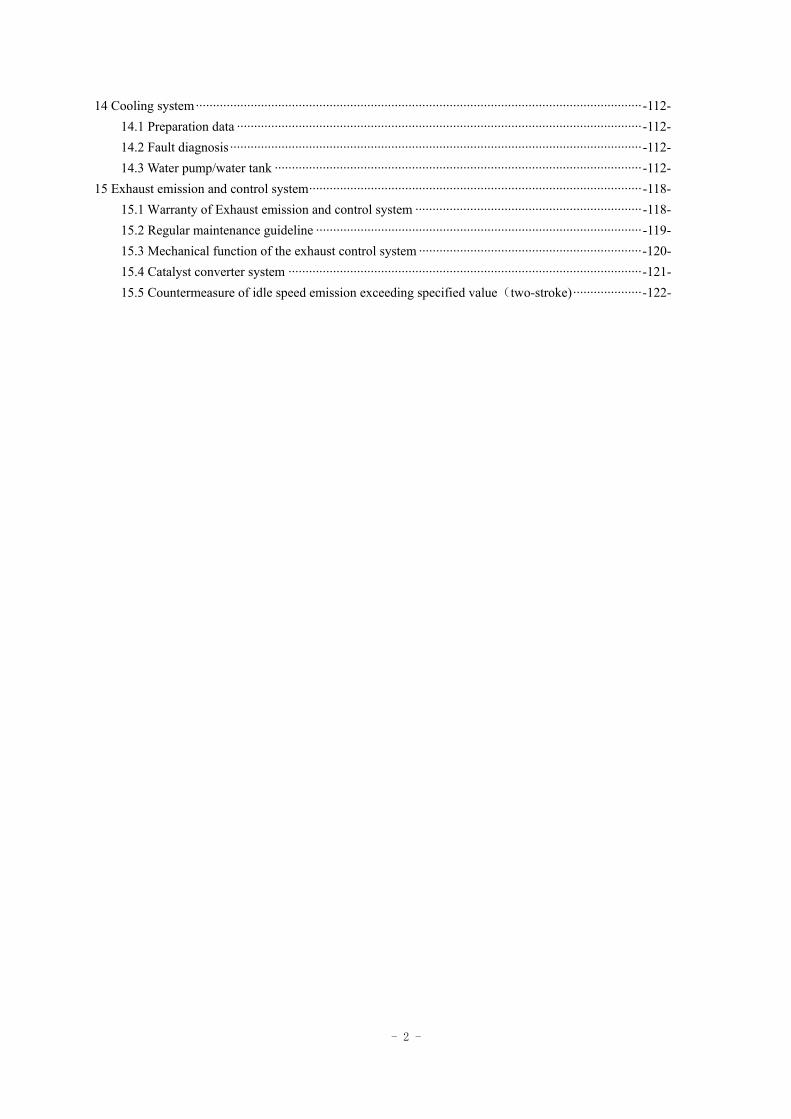
14 Cooling system··································································································································-112- 14.1 Preparation data ······················································································································-112- 14.2 Fault diagnosis ························································································································-112- 14.3 Water pump/water tank ···········································································································-112-
15 Exhaust emission and control system·································································································-118- 15.1 Warranty of Exhaust emission and control system ··································································-118- 15.2 Regular maintenance guideline ·······························································································-119- 15.3 Mechanical function of the exhaust control system ·································································-120- 15.4 Catalyst converter system ·······································································································-121- 15.5 Countermeasure of idle speed emission exceeding specified value(two-stroke)····················-122-
- 3 -
Preface This Manual explains the maintenance of Generic Trigger 50ccm The documents to be prepared are the maintenance manual and all the operations are included in, please read the manual prior to operation. Inspection and Adjustment explains the gist of inspection and adjustment; the maintenance of safety of vehicle and the performance of each part should come into force since regular inspection. After Chapter I is the explanation of the gist of disassembly, assembly and inspection of engine, entire vehicle and electric fittings. There are exploded view, system diagram, maintenance, fault diagnosis and explanation before each chapter. Notice: For the universal parts of both types of motorcycle, this manual does not seperate the explanation. There is no prior individual notification on the alteration of mode or structure of motorcycle and the actual product shall prevail if there is discrepancy between the photos, pictures or explanation contained in this Manual and the actual product.
- 4 -
Documents to be prepared General safety Maintenance regulation Specififcation sheet Troubleshooting
General safety Carbon monoxide The engine should be started in ventilated area other than closed area. Attention The exhaust contains toxic gas, carbon monoxide, which can numb people and may result in death.
The engine should be started in an open area and the exhaust scavenging system should be applied if the engine has to be started in a closed area.
Gasoline The operation should be made in a ventilated area and smoking or lighting fires should be strictly forbidden in working space or the place stored gasoline.
- 5 -
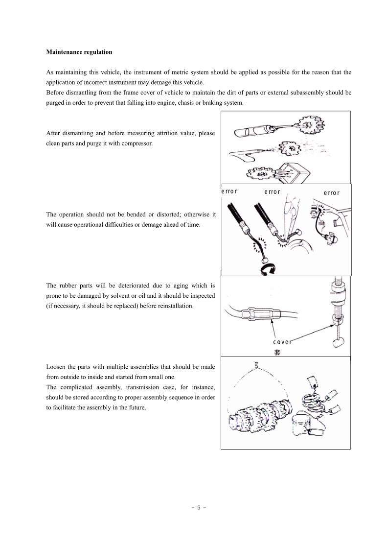
Maintenance regulation As maintaining this vehicle, the instrument of metric system should be applied as possible for the reason that the application of incorrect instrument may demage this vehicle. Before dismantling from the frame cover of vehicle to maintain the dirt of parts or external subassembly should be purged in order to prevent that falling into engine, chasis or braking system. After dismantling and before measuring attrition value, please clean parts and purge it with compressor. The operation should not be bended or distorted; otherwise it will cause operational difficulties or demage ahead of time. The rubber parts will be deteriorated due to aging which is prone to be damaged by solvent or oil and it should be inspected (if necessary, it should be replaced) before reinstallation. Loosen the parts with multiple assemblies that should be made from outside to inside and started from small one. The complicated assembly, transmission case, for instance, should be stored according to proper assembly sequence in order to facilitate the assembly in the future.
error error error
cover
- 6 -
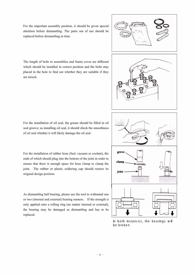
For the important assembly position, it should be given special attention before dismantling. The parts out of use should be replaced before dismantling in time. The length of bolts to assemblies and frame cover are different which should be installed in correct position and the bolts may placed in the hole to find out whether they are suitable if they are mixed. For the installation of oil seal, the grease should be filled in oil seal groove; as installing oil seal, it should check the smoothness of oil seal whether it will likely damage the oil seal. For the installation of rubber hose (fuel, vacuum or coolant), the ends of which should plug into the bottom of the joint in order to ensure that there is enough space for hose clamp to clamp the joint. The rubber or plastic soldering cup should restore its original design position. As dismantling ball bearing, please use the tool to withstand one or two (internal and external) bearing runners. If the strength is only applied onto a rolling ring (no matter internal or external), the bearing may be damaged as dismantling and has to be replaced.
In both instances, the bearings will be broken
- 7 -
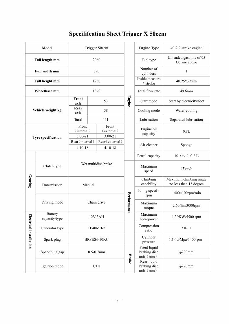
Specififcation Sheet Trigger X 50ccm
Model Trigger 50ccm Engine Type 40-2 2-stroke engine
Full length mm 2060 Fuel type Unleaded gasoline of 95 Octane above
Full width mm 890 Number of cylinders 1
Full height mm 1230 Inside measure * stroke 40.25*39mm
Wheelbase mm 1370 Total flow rate 49.6mm
Front axle 53 Start mode Start by electricity/foot
Rear axle 58 Cooling mode Water-cooling Vehicle weight kg
Total 111 Lubrication Separated lubrication
Front(internal)
Front(external)
3.00-21 3.00-21
Engine oil capacity 0.8L
Rear(internal) Rear(external) Tyre specification
4.10-18 4.10-18 Air cleaner Sponge
Engine
Petrol capacity 10(+/-)0.2 L
Clutch type Wet multidisc brake Maximum
speed 45km/h
Climbing capability
Maximum climbing angle no less than 15 degree Transmission Manual
Idling speed - rpm 1400±100rpm/min
Gearing
Driving mode Chain drive Maximum torque 2.60Nm/3000rpm
Battery capacity/type 12V 3AH Maximum
horsepower 1.39KW/5500 rpm
Generator type 1E40MB-2 Compression ratio 7.0:1
Spark plug BR8ES/F10KC
Performance
Cylinder pressure 1.1-1.3Mpa/1400rpm
Spark plug gap 0.5-0.7mm Front liquid braking disc unit(mm)
φ230mm
Electrical installation
Ignition mode CDI
Brake Rear liquid
braking disc unit(mm)
φ220mm
- 8 -
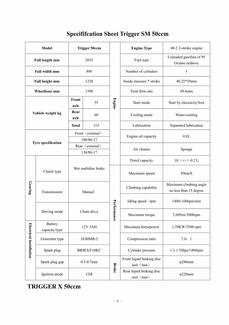
Specififcation Sheet Trigger SM 50ccm
Model Trigger 50ccm Engine Type 40-2 2-stroke engine
Full length mm 2035 Fuel type Unleaded gasoline of 95
Octane orabove
Full width mm 890 Number of cylinders 1
Full height mm 1230 Inside measure * stroke 40.25*39mm
Wheelbase mm 1390 Total flow rate 49.6mm
Front axle
55 Start mode Start by electricity/foot
Rear axle
60 Cooling mode Water-cooling Vehicle weight kg
Total 115 Lubrication Separated lubrication
Front(external)
100/80-17 Engine oil capacity 0.8L
Rear(external) Tyre specification
130/80-17 Air cleaner Sponge
Engine
Petrol capacity 10(+/-)0.2 L
Clutch type Wet multidisc brake
Maximum speed 45km/h
Climbing capability Maximum climbing angle
no less than 15 degree Transmission Manual
Idling speed - rpm 1400±100rpm/min G
earing
Driving mode Chain drive Maximum torque 2.60Nm/3000rpm
Battery capacity/type
12V 3AH Maximum horsepower 1.39KW/5500 rpm
Generator type 1E40MB-2 Compression ratio 7.0:1
Spark plug BR8ES/F10KC
Performance
Cylinder pressure 1.1-1.3Mpa/1400rpm
Spark plug gap 0.5-0.7mm Front liquid braking disc
unit(mm) φ280mm
Electrical installation
Ignition mode CDI
Brake Rear liquid braking disc
unit(mm) φ220mm
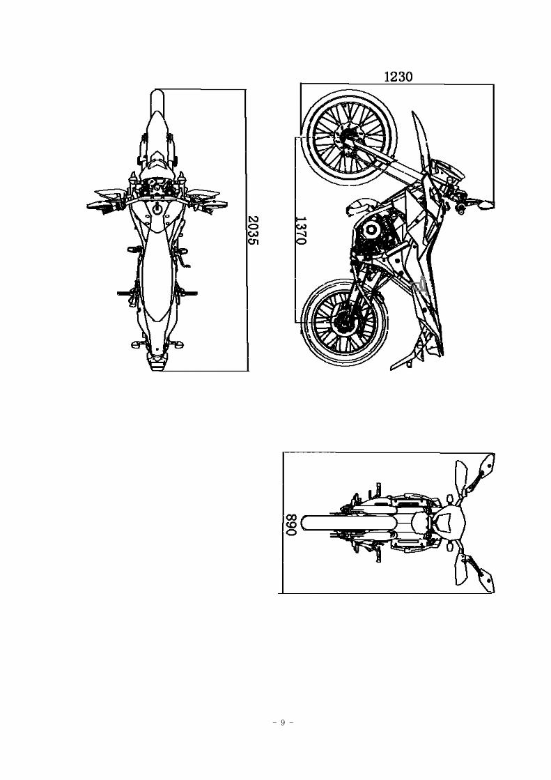
TRIGGER X 50ccm
- 9 -
- 10 -
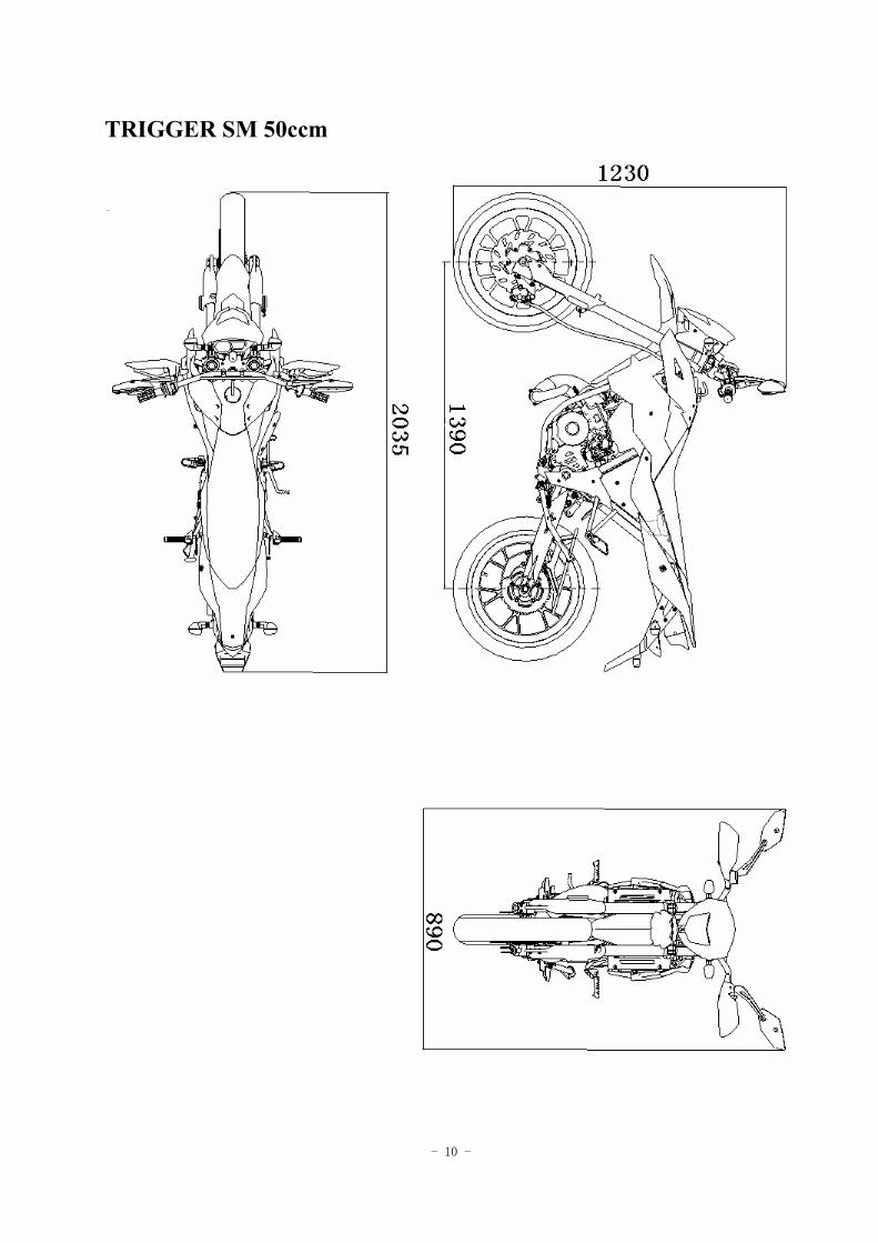
TRIGGER SM 50ccm
- 11 -
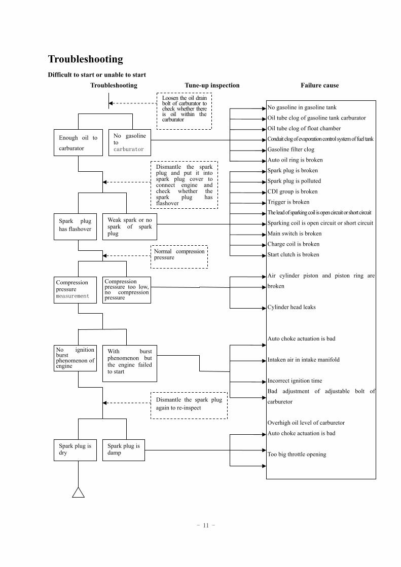
Troubleshooting Difficult to start or unable to start
Troubleshooting Tune-up inspection Failure cause
Enough oil to
carburator
No gasoline to carburator
Loosen the oil drain bolt of carburator to check whether there is oil within the carburator
Spark plug has flashover
Weak spark or no spark of spark plug
Dismantle the spark plug and put it into spark plug cover to connect engine and check whether the spark plug has flashover
Compression pressure measurement
Compression pressure too low, no compression pressure
Normal compression pressure
No ignition burst phenomenon of engine
With burst phenomenon but the engine failed to start
Spark plug is damp
Spark plug is dry
Dismantle the spark plug again to re-inspect
No gasoline in gasoline tank
Oil tube clog of gasoline tank carburator
Oil tube clog of float chamber
Conduit clog of evaporation control system of fuel tank
Gasoline filter clog
Auto oil ring is broken
Spark plug is broken
Spark plug is polluted
CDI group is broken
Trigger is broken
The lead of sparking coil is open circuit or short circuit
Sparking coil is open circuit or short circuit
Main switch is broken
Charge coil is broken
Start clutch is broken
Air cylinder piston and piston ring are
broken
Cylinder head leaks
Auto choke actuation is bad
Intaken air in intake manifold
Incorrect ignition time
Bad adjustment of adjustable bolt of
carburetor
Overhigh oil level of carburetor
Auto choke actuation is bad
Too big throttle opening
- 12 -
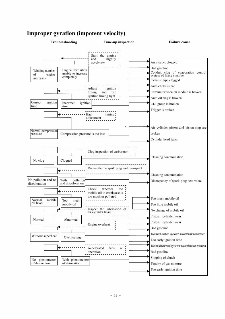
Improper gyration (impotent velocity) Troubleshooting Tune-up inspection Failure cause
Winding number of engine increases
Engine revolution unable to increase completely
Start the engine and slightly accelerate
Correct ignition time
Incorrect ignition time
Adjust ignition timing and use ignition timing light
Normal compression pressure Compression pressure is too low
Bad timing adjustment
No clog Clogged
With pollution and discoloration
No pollution and no discoloration
Dismantle the spark plug and re-inspect
Clog inspection of carburetor
Normal Abnormal
Without superheat Overheating
No phenomenon of detonation
With phenomenon of detonation
Accelerated drive or operation
Engine overheat
Inspect the lubrication of air cylinder head
Normal mobile oil level
Too much mobile oil
Check whether the mobile oil in crankcase is too much or polluted
Air cleaner clogged
Bad gasoline Conduit clog of evaporation control system of firing chamber Exhaust pipe clogged
Auto choke is bad
Carburetor vacuum module is broken
Auto oil ring is broken
CDI group is broken
Trigger is broken
Air cylinder piston and piston ring are
broken
Cylinder head leaks
Cleaning contamination
Cleaning contamination
Discrepancy of spark-plug heat value
Too much mobile oil
Too little mobile oil
No change of mobile oil
Piston,cylinder wear
Piston,cylinder wear
Bad gasoline
Too much carbon laydown in combustion chamber
Too early ignition time
Too much carbon laydown in combustion chamber
Bad gasoline
Slipping of clutch
Tenuity of gas mixture
Too early ignition time
- 13 -
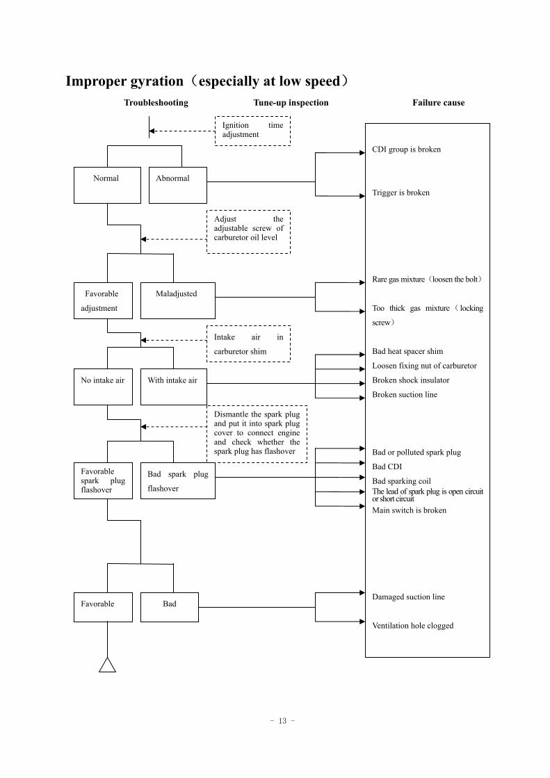
Improper gyration(especially at low speed) Troubleshooting Tune-up inspection Failure cause
Normal Abnormal
Ignition time adjustment
Favorable
adjustment
Maladjusted
Adjust the adjustable screw of carburetor oil level
No intake air With intake air
Dismantle the spark plug and put it into spark plug cover to connect engine and check whether the spark plug has flashover
Favorable spark plug flashover
Bad spark plug
flashover
Bad Favorable
Intake air in
carburetor shim
CDI group is broken
Trigger is broken
Rare gas mixture(loosen the bolt)
Too thick gas mixture( locking
screw)
Bad heat spacer shim
Loosen fixing nut of carburetor
Broken shock insulator
Broken suction line
Bad or polluted spark plug
Bad CDI
Bad sparking coil The lead of spark plug is open circuit or short circuit Main switch is broken
Damaged suction line
Ventilation hole clogged
- 14 -
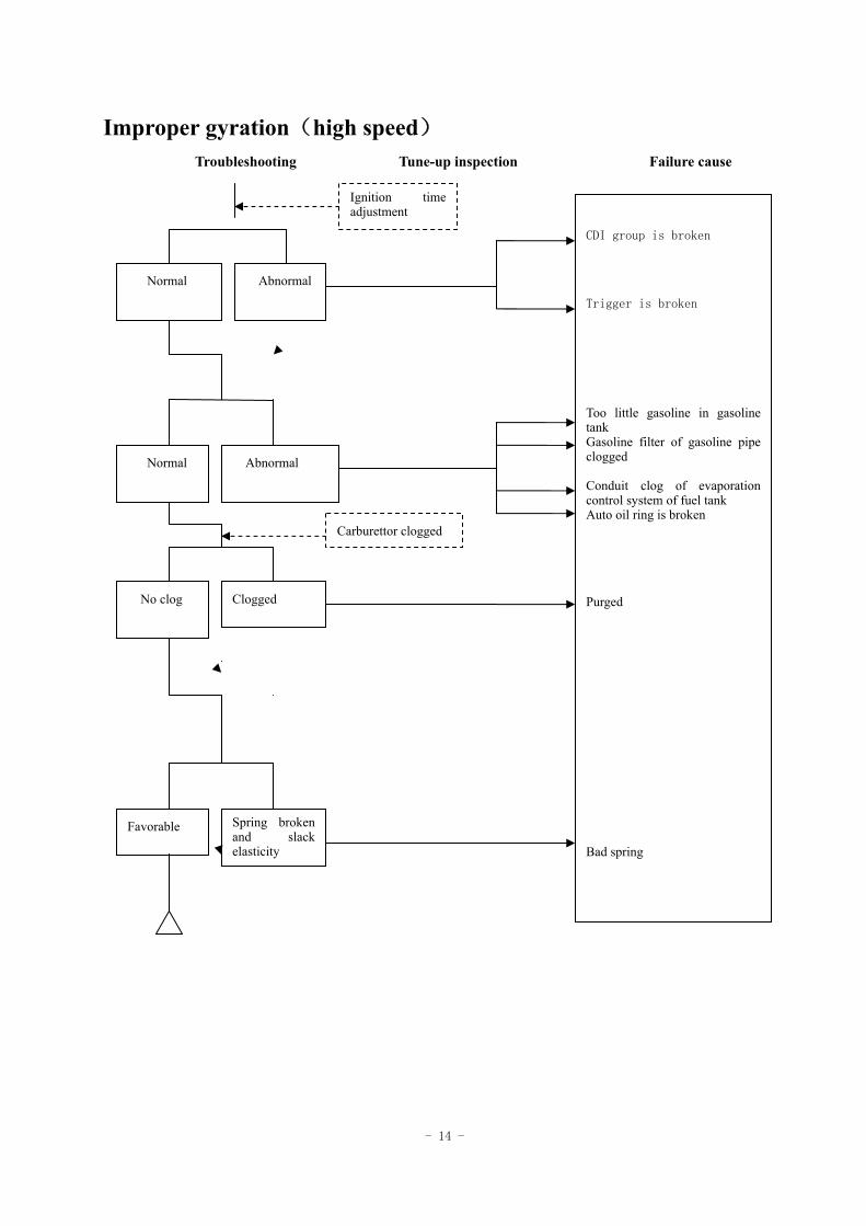
Improper gyration(high speed) Troubleshooting Tune-up inspection Failure cause
Normal
Abnormal
Ignition time adjustment
Normal
Abnormal
No clog Clogged
Spring broken and slack elasticity
Favorable
Carburettor clogged
CDI group is broken
Trigger is broken
Too little gasoline in gasoline tank Gasoline filter of gasoline pipe clogged Conduit clog of evaporation control system of fuel tank Auto oil ring is broken
Purged
Bad spring
- 15 -
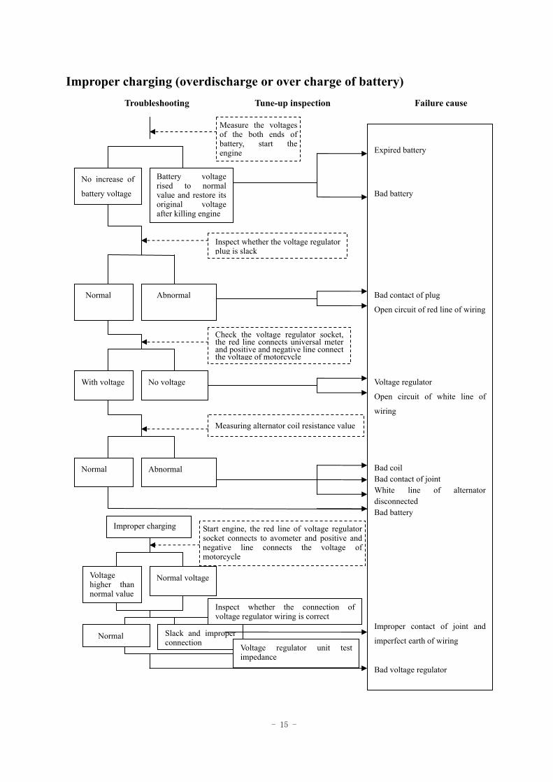
Improper charging (overdischarge or over charge of battery) Troubleshooting Tune-up inspection Failure cause
No increase of
battery voltage
Battery voltage rised to normal value and restore its original voltage after killing engine
Measure the voltages of the both ends of battery, start the engine
Normal Abnormal
Inspect whether the voltage regulator plug is slack
With voltage No voltage
Measuring alternator coil resistance value
Normal Abnormal
Normal voltage Voltage higher than normal value
Start engine, the red line of voltage regulator socket connects to avometer and positive and negative line connects the voltage of motorcycle
Check the voltage regulator socket, the red line connects universal meter and positive and negative line connect the voltage of motorcycle
Improper charging
Normal Slack and improper connection
Inspect whether the connection of voltage regulator wiring is correct
Voltage regulator unit test impedance
Expired battery
Bad battery
Bad contact of plug
Open circuit of red line of wiring
Voltage regulator
Open circuit of white line of
wiring
Bad coil Bad contact of joint White line of alternator disconnected Bad battery
Improper contact of joint and
imperfect earth of wiring
Bad voltage regulator
- 16 -
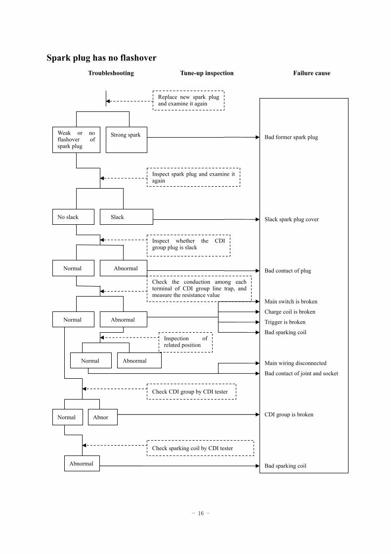
Spark plug has no flashover Troubleshooting Tune-up inspection Failure cause
Weak or no flashover of spark plug
Strong spark
Replace new spark plug and examine it again
No slack Slack
Inspect spark plug and examine it again
Normal Abnormal
Check the conduction among each terminal of CDI group line trap, and measure the resistance value
Normal Abnormal
Abnormal Normal
Inspection of related position
Inspect whether the CDI group plug is slack
Normal Abnor
Abnormal
Check sparking coil by CDI tester
Check CDI group by CDI tester
Bad former spark plug
Slack spark plug cover
Bad contact of plug
Main switch is broken
Charge coil is broken
Trigger is broken
Bad sparking coil
Main wiring disconnected
Bad contact of joint and socket
CDI group is broken
Bad sparking coil
- 17 -
Inspection/adjustment
Preparation of documents Cylinder pressure
Check list of constant maintenance Gear mobile oil
Engine mobile oil/oil strainer Changing gear oil
Gasoline filter Driving chain
Inspection/adjustment of accelerator's pull wire Clearance of front/rear brake
Air cleaner Front shoe block abrasion
Spark plug Head lighting
Battery Clutch
Carburator Front/rear suspension system
Ignition timing Bolt/nut/fixture
Rim/tyre Tyre specification
Steering post bearing and handle fixture
Preparation requirement
General Warning! •Before starting engine, please confirm whether there is favorable ventilation and do not start engine in a closed location for that the exhaust gas contains carbon monoxide which may numb or kill people. •Under certain condition, gasoline is prone to volatilize and explode so that the working place should be ventilated and kill the engine and should be free from smoking and lighting in the working area or oil storage.
- 18 -
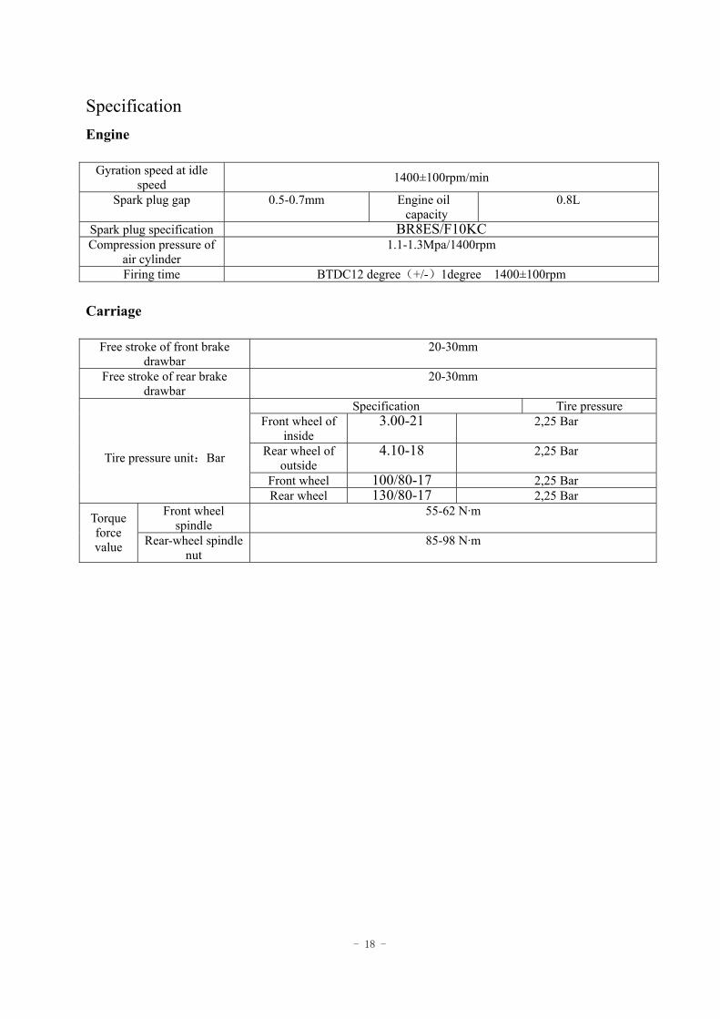
Specification Engine
Gyration speed at idle speed 1400±100rpm/min
Spark plug gap 0.5-0.7mm Engine oil capacity
0.8L
Spark plug specification BR8ES/F10KC Compression pressure of
air cylinder 1.1-1.3Mpa/1400rpm
Firing time BTDC12 degree(+/-)1degree 1400±100rpm Carriage
Free stroke of front brake drawbar
20-30mm
Free stroke of rear brake drawbar
20-30mm
Specification Tire pressure Front wheel of
inside 3.00-21 2,25 Bar
Rear wheel of outside
4.10-18 2,25 Bar
Front wheel 100/80-17 2,25 Bar
Tire pressure unit:Bar
Rear wheel 130/80-17 2,25 Bar Front wheel
spindle 55-62 N·m Torque
force value Rear-wheel spindle
nut 85-98 N·m
- 19 -
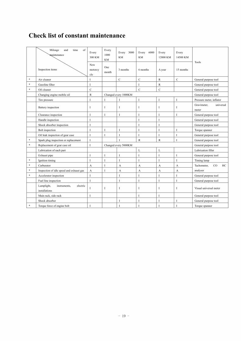
Check list of constant maintenance
Every
300 KM
Every
1000
KM
Every 3000
KM
Every 6000
KM
Every
12000 KM
Every
14500 KM
Mileage and time of
maintenance
Inspection items
New
motorcy
cle
One
month 3 months 6 months A year 15 months
Tools
* Air cleaner I C C R C General purpose tool
* Gasoline filter I I R General purpose tool
* Oil cleaner C C C General purpose tool
Changing engine mobile oil R Changed every 1000KM General purpose tool
Tire pressure I I I I I I Pressure meter, inflator
Battery inspection I I I I I I Gravimeter, universal
meter
Clearance inspection I I I I I I General purpose tool
Handle inspection I I I General purpose tool
Shock absorber inspection I I I General purpose tool
Bolt inspection I I I I I I Torque spanner
Oil leak inspection of gear case I I I I I I General purpose tool
* Spark plug inspection or replacement I I R R I General purpose tool
* Replacement of gear case oil I Changed every 5000KM General purpose tool
Lubrication of each part L L Lubrication filler
Exhaust pipe I I I I I I General purpose tool
* Ignition timing I I I I I I Timing lamp
* Carburator A I A A A A
* Inspection of idle speed and exhaust gas A I A A A A
Tachometer, CO HC
analyser
* Accelerator inspection I I I I I General purpose tool
Fuel line inspection I I I I I General purpose tool
Lamplight, instruments, electric
installations I I I I I I Visual universal meter
Main rack, side rack I I I General purpose tool
Shock absorber I I I I General purpose tool
* Torque force of engine bolt I I I I I Torque spanner
- 20 -
Pre-inspection 1 Ignition system - maintenance and inspection of ignition malfunction of distinct continuity, engine failed to
start and superheat of afterburning. 2 Carbon laydown purging - purging the carbon laydown in the head of air cylinder, piston head and exhaust air
system when the horsepower is in distinct deficiency. 3 Piston, air cylinder - excessive wear of air cylinder and cylinder smoothness, please replace.
Please be inspected at the dealer in Generic regularly in order to keep motorcycle under its optimized condition.
The said table is based on that the motorcycle runs 1000km per month.
I - inspection, A - adjustment, R - replacement, C - clean, L - lubrication
Remarks: 1. " * " for the project of exhaust emission, according to the provisions of State Environmental Protection Administration of
China, the maintenance should be implemented according to the specifications of the Instruction Manual of the Company and
should not be adjusted or repaired without permission, otherwise the company will not take any responsibility.
2. If the motorcycle is driven on the sandstone road or under the environment of severe contamination, the times of purging air
filtrator should be increased to prolong the service life.
3. For the motorcycle which is frequently driven at high speed or the milage is large the frequency of maintenance should be
increased.
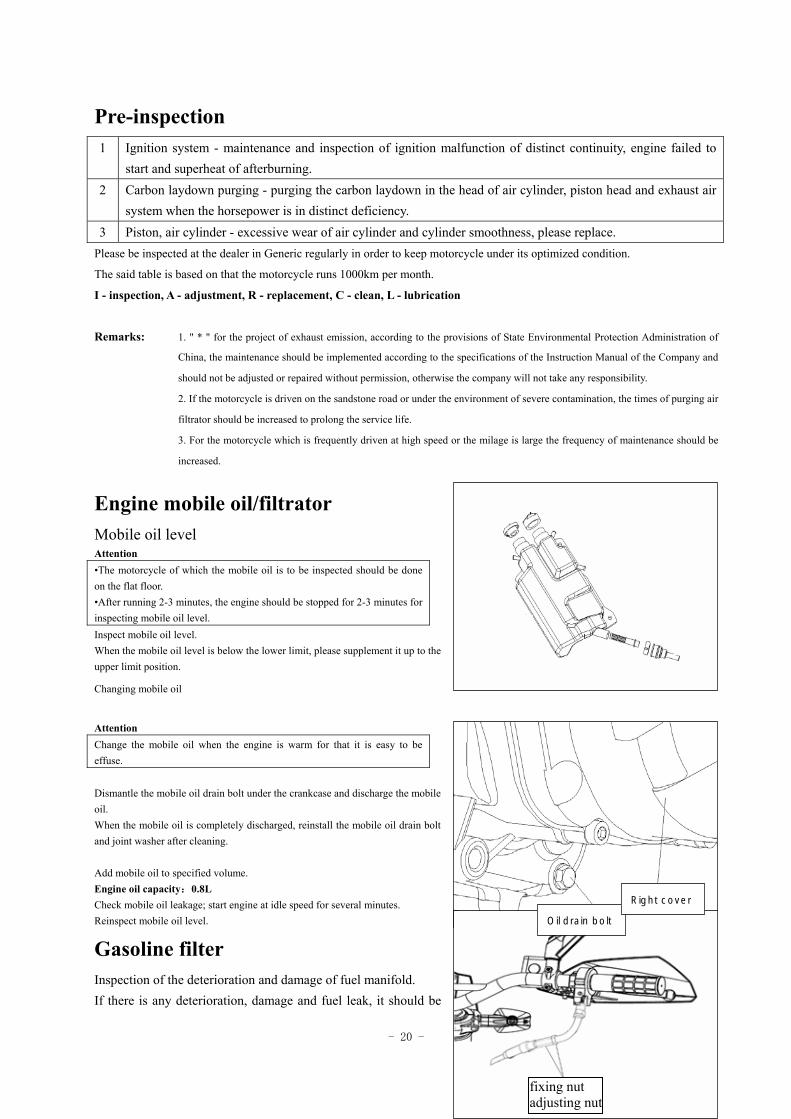
Engine mobile oil/filtrator Mobile oil level Attention •The motorcycle of which the mobile oil is to be inspected should be done on the flat floor. •After running 2-3 minutes, the engine should be stopped for 2-3 minutes for inspecting mobile oil level. Inspect mobile oil level. When the mobile oil level is below the lower limit, please supplement it up to the upper limit position.
Changing mobile oil
Attention Change the mobile oil when the engine is warm for that it is easy to be effuse. Dismantle the mobile oil drain bolt under the crankcase and discharge the mobile oil. When the mobile oil is completely discharged, reinstall the mobile oil drain bolt and joint washer after cleaning. Add mobile oil to specified volume. Engine oil capacity:0.8L Check mobile oil leakage; start engine at idle speed for several minutes. Reinspect mobile oil level.
Gasoline filter Inspection of the deterioration and damage of fuel manifold. If there is any deterioration, damage and fuel leak, it should be
fixing nut adjusting nut
Oil drain bolt
Right cover
- 21 -
replaced with new product. Warning! Smoking or lighting fires are strictly forbidened.
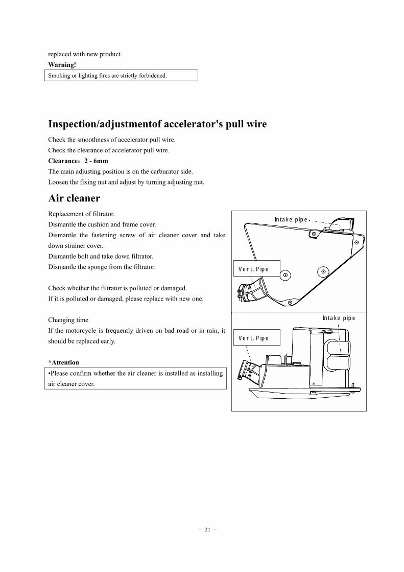
Inspection/adjustmentof accelerator's pull wire Check the smoothness of accelerator pull wire. Check the clearance of accelerator pull wire. Clearance:2 - 6mm The main adjusting position is on the carburator side. Loosen the fixing nut and adjust by turning adjusting nut.
Air cleaner Replacement of filtrator. Dismantle the cushion and frame cover. Dismantle the fastening screw of air cleaner cover and take down strainer cover. Dismantle bolt and take down filtrator. Dismantle the sponge from the filtrator. Check whether the filtrator is polluted or damaged. If it is polluted or damaged, please replace with new one. Changing time If the motorcycle is frequently driven on bad road or in rain, it should be replaced early. *Attention •Please confirm whether the air cleaner is installed as installing air cleaner cover.
Intake pipe
Intake pipe
Vent. Pipe
Vent. Pipe
- 22 -
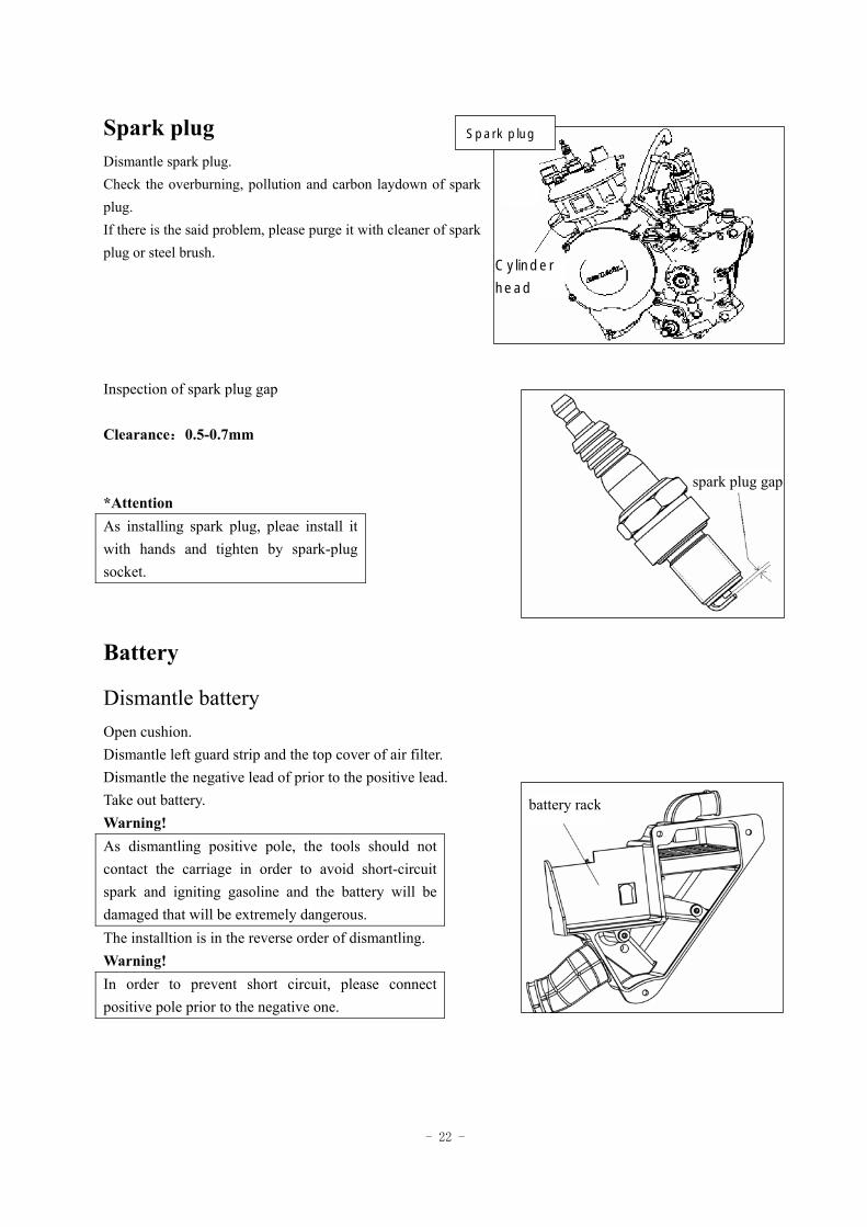
Spark plug Dismantle spark plug. Check the overburning, pollution and carbon laydown of spark plug. If there is the said problem, please purge it with cleaner of spark plug or steel brush. Inspection of spark plug gap Clearance:0.5-0.7mm *Attention As installing spark plug, pleae install it with hands and tighten by spark-plug socket.
Battery
Dismantle battery Open cushion. Dismantle left guard strip and the top cover of air filter. Dismantle the negative lead of prior to the positive lead. Take out battery. Warning! As dismantling positive pole, the tools should not contact the carriage in order to avoid short-circuit spark and igniting gasoline and the battery will be damaged that will be extremely dangerous. The installtion is in the reverse order of dismantling. Warning! In order to prevent short circuit, please connect positive pole prior to the negative one.
Cylinder
head
spark plug gap
battery rack
Spark plug
- 23 -
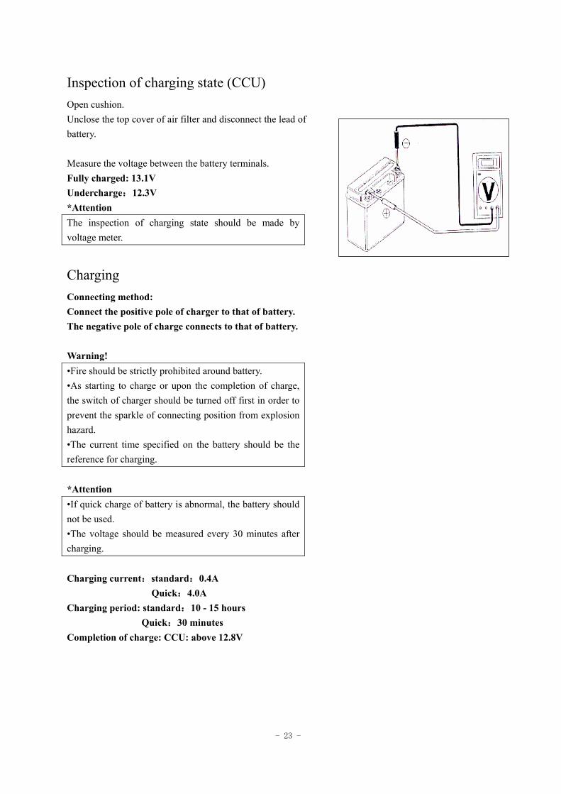
Inspection of charging state (CCU) Open cushion. Unclose the top cover of air filter and disconnect the lead of battery. Measure the voltage between the battery terminals. Fully charged: 13.1V Undercharge:12.3V *Attention The inspection of charging state should be made by voltage meter.
Charging Connecting method: Connect the positive pole of charger to that of battery. The negative pole of charge connects to that of battery. Warning! •Fire should be strictly prohibited around battery. •As starting to charge or upon the completion of charge, the switch of charger should be turned off first in order to prevent the sparkle of connecting position from explosion hazard. •The current time specified on the battery should be the reference for charging. *Attention •If quick charge of battery is abnormal, the battery should not be used. •The voltage should be measured every 30 minutes after charging. Charging current:standard:0.4A Quick:4.0A Charging period: standard:10 - 15 hours Quick:30 minutes Completion of charge: CCU: above 12.8V
- 24 -
Carburator
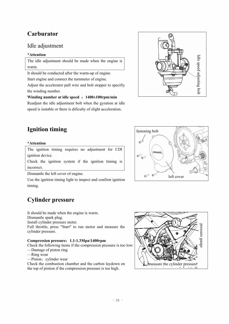
Idle adjustment *Attention The idle adjustment should be made when the engine is warm. It should be conducted after the warm-up of engine. Start engine and connect the turnmeter of engine. Adjust the accelerator pull wire and bolt stopper to specifiy the winding number. Winding number at idle speed :1400±100rpm/min Readjust the idle adjustment bolt when the gyration at idle speed is instable or there is dificulty of slight acceleration.
Ignition timing
*Attention The ignition timing requires no adjustment for CDI ignition device. Check the ignition system if the ignition timing is incorrect. Dismantle the left cover of engine. Use the ignition timing light to inspect and confirm ignition timing.
Cylinder pressure
It should be made when the engine is warm. Dismantle spark plug. Install cylinder pressure meter. Full throttle, press "Start" to run motor and measure the cylinder pressure. Compression pressure:1.1-1.3Mpa/1400rpm Check the following items if the compression pressure is too low: —Damage of piston ring —Ring wear —Piston,cylinder wear Check the combustion chamber and the carbon laydown on the top of pistion if the compression pressure is too high.
Idle speed adjusting bolt
left cover
fastening bolt
pressure gauge
measure the cylinder pressure
- 25 -
Gear mobile oil
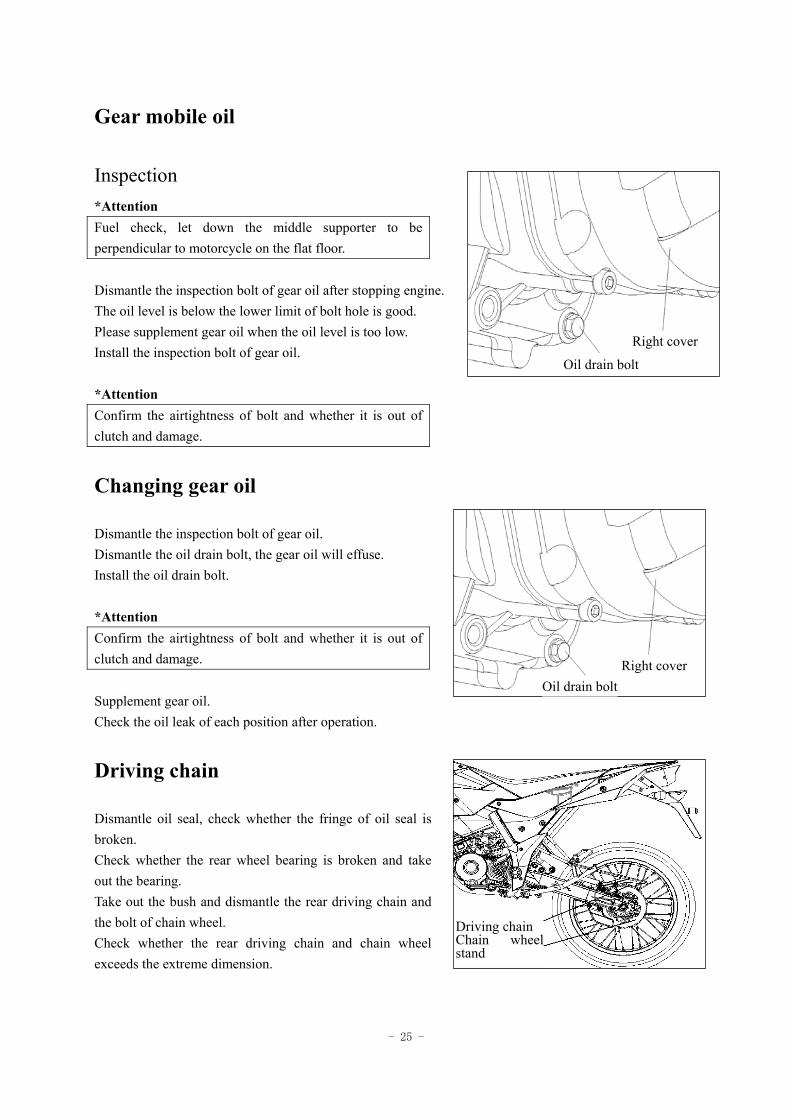
Inspection *Attention Fuel check, let down the middle supporter to be perpendicular to motorcycle on the flat floor. Dismantle the inspection bolt of gear oil after stopping engine. The oil level is below the lower limit of bolt hole is good. Please supplement gear oil when the oil level is too low. Install the inspection bolt of gear oil. *Attention Confirm the airtightness of bolt and whether it is out of clutch and damage.
Changing gear oil
Dismantle the inspection bolt of gear oil. Dismantle the oil drain bolt, the gear oil will effuse. Install the oil drain bolt. *Attention Confirm the airtightness of bolt and whether it is out of clutch and damage. Supplement gear oil. Check the oil leak of each position after operation.
Driving chain
Dismantle oil seal, check whether the fringe of oil seal is broken. Check whether the rear wheel bearing is broken and take out the bearing. Take out the bush and dismantle the rear driving chain and the bolt of chain wheel. Check whether the rear driving chain and chain wheel exceeds the extreme dimension.
Driving chainChain wheel stand
Right cover
Oil drain bolt
Right coverOil drain bolt
- 26 -
Clearance of front/rear brake
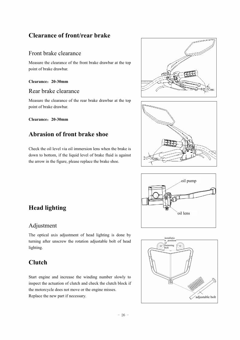
Front brake clearance Measure the clearance of the front brake drawbar at the top point of brake drawbar. Clearance:20-30mm
Rear brake clearance Measure the clearance of the rear brake drawbar at the top point of brake drawbar. Clearance:20-30mm
Abrasion of front brake shoe
Check the oil level via oil immersion lens when the brake is down to bottom, if the liquid level of brake fluid is against the arrow in the figure, please replace the brake shoe.
Head lighting
Adjustment The optical axis adjustment of head lighting is done by turning after unscrew the rotation adjustable bolt of head lighting.
Clutch
Start engine and increase the winding number slowly to inspect the actuation of clutch and check the clutch block if the motorcycle does not move or the engine misses. Replace the new part if necessary.
oil pump
oil lens
installation position of fastening bolt
adjustable bolt
- 27 -
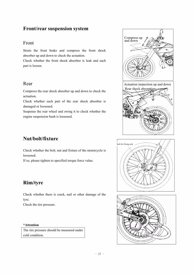
Front/rear suspension system
Front Strain the front brake and compress the front shock absorber up and down to check the actuation. Check whether the front shock absorber is leak and each part is loosen.
Rear Compress the rear shock absorber up and down to check the actuation. Check whether each part of the rear shock absorber is damaged or loosened. Suspense the rear wheel and swing it to check whether the engine suspension bush is loosened.
Nut/bolt/fixture
Check whether the bolt, nut and fixture of the motorcycle is loosened. If so, please tighten to specified torque force value.
Rim/tyre
Check whether there is crack, nail or other damage of the tyre. Check the tire pressure. *Attention The tire pressure should be measured under cold condition.
Compress up and down
Actuation inspection up and down Rear shock absorption
bolt for fixing axle
- 28 -
Specified pressure unit:Kpa Specification Tire pressure
Front wheel 3.00-21 225
QJ50-23 Rear wheel 4.10-18 225
Front wheel 100/80-17 225
QJ50-23A Rear wheel 130/80-17 225
Tyre specification
Front wheel of inside
3.00-21
Front wheel of outside
3.00-21
Rear wheel of inside
4.10-18 QJ50-23
Rear wheel of outside
4.10-18
Front wheel 100/80-17 QJ50-23A Rear wheel 130/80-17 Check whether the front wheel spindle is loosened. Check whether the nuts of rear wheel are loosened. If so, please tighten to specified torque force value. Torque force value: Front wheel spindle 55-62 N·m Rear-wheel spindle nut 85-98 N·m
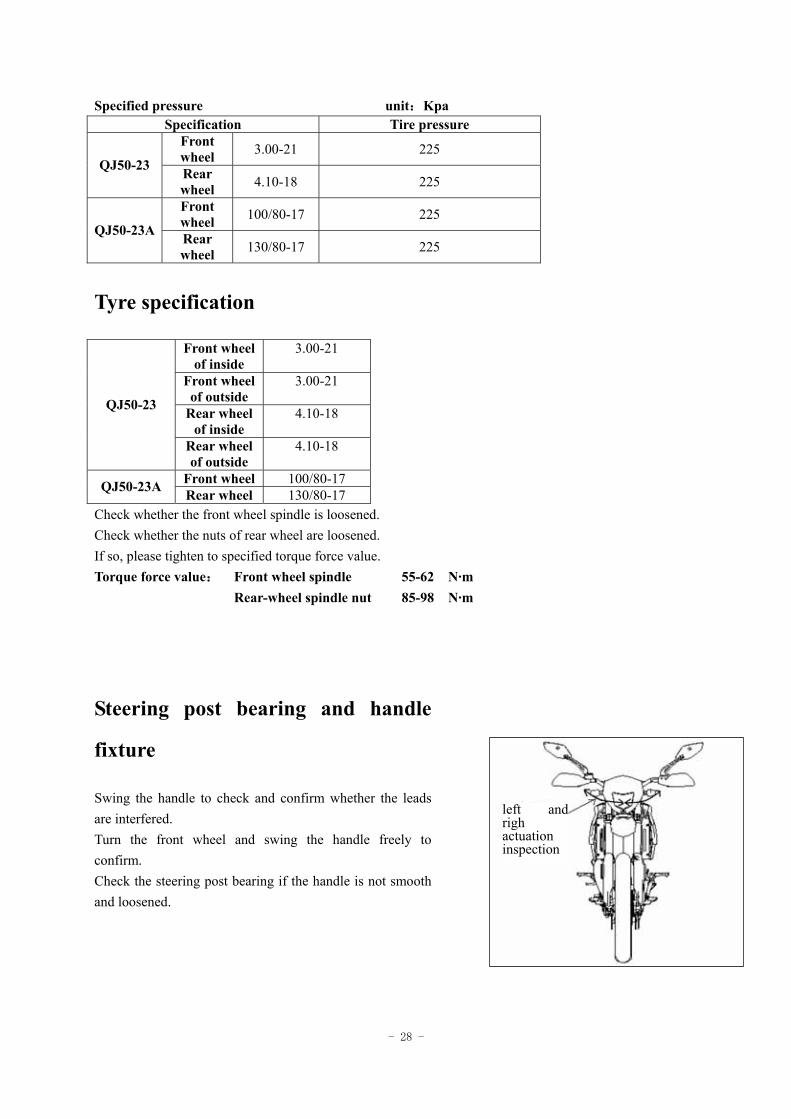
Steering post bearing and handle
fixture
Swing the handle to check and confirm whether the leads are interfered. Turn the front wheel and swing the handle freely to confirm. Check the steering post bearing if the handle is not smooth and loosened.
left and righ actuation inspection
- 29 -
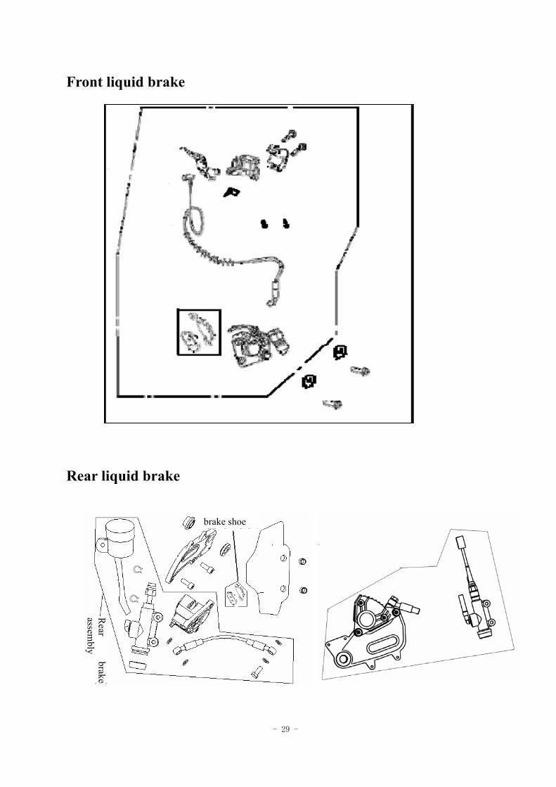
Front liquid brake
Rear liquid brake
brake shoe
Rear
brakeassem
bly
- 30 -
1 Brake
Maintenance instruction ------------------------ 1.1
Fault diagnosis ----------------------------------- 1.2
Front hydraulic brake ----------------------------1.3
Rear hydraulic brake ---------------------------- 1.4
1.1 Maintenance instruction
Matters needing attention in operation * Note
*Inspect the brake before riding the motorcycle.*
1.1.1 Specification Item Standard value (mm) Allowable limit(mm)
thickness of front brake disc 4.0 - thickness of front brake pad 4.5 3.0 thickness of rear brake disc 4.0 - thickness of rear brake pad 7.0 3.0
QJ50-23 diameter of front hydraulic brake φ230mm Diameter of rear hydraulic brake φ220mm
QJ50-23A diameter of front hydraulic brake φ280mm Diameter of rear hydraulic brake φ220mm
1.1.2 torque value Fixing bolt of brake disc 22-29 N·m Mounting bolt of brake caliper 22-29 N·m
1.2 Fault diagnosis
Brake
Bad braking quality Slow brake or tight rod 1. Unfavorable brake adjustment 1. Unfavorable brake adjustment
•The braking components can not be spoiled by oil stain in installation or disassembly. •Rinse with stipulated cleaning agent in order to avoid reduction of braking quality.
- 31 -
2. Brake pad worn out 2. Brake pad worn out 3. Improper installation of brake pad 3. Improper installation of brake pad 4. Brake pad polluted
Strange sound in braking
1. Brake pad worn out 2. Brake pad polluted
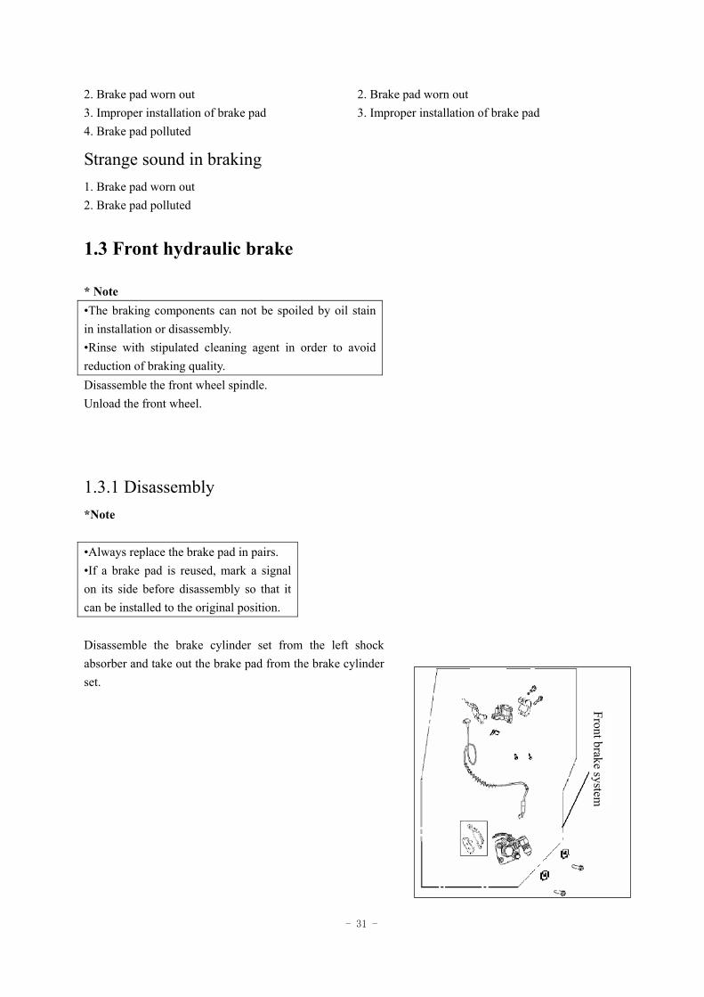
1.3 Front hydraulic brake
* Note •The braking components can not be spoiled by oil stain in installation or disassembly. •Rinse with stipulated cleaning agent in order to avoid reduction of braking quality. Disassemble the front wheel spindle. Unload the front wheel.
1.3.1 Disassembly *Note •Always replace the brake pad in pairs. •If a brake pad is reused, mark a signal on its side before disassembly so that it can be installed to the original position. Disassemble the brake cylinder set from the left shock absorber and take out the brake pad from the brake cylinder set.
Front brake system
- 32 -
1.3.2 Inspection
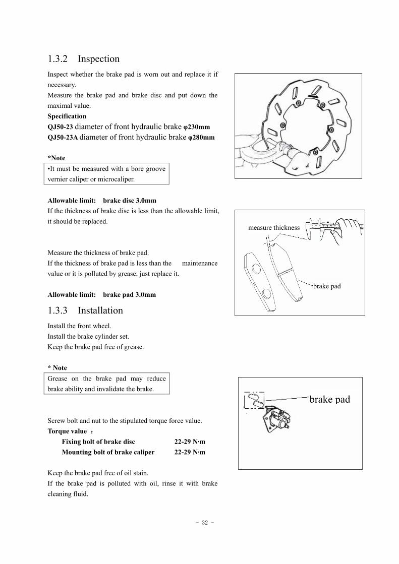
Inspect whether the brake pad is worn out and replace it if necessary. Measure the brake pad and brake disc and put down the maximal value. Specification QJ50-23 diameter of front hydraulic brake φ230mm QJ50-23A diameter of front hydraulic brake φ280mm *Note •It must be measured with a bore groove vernier caliper or microcaliper. Allowable limit: brake disc 3.0mm If the thickness of brake disc is less than the allowable limit, it should be replaced. Measure the thickness of brake pad. If the thickness of brake pad is less than the maintenance value or it is polluted by grease, just replace it. Allowable limit: brake pad 3.0mm
1.3.3 Installation
Install the front wheel. Install the brake cylinder set. Keep the brake pad free of grease. * Note Grease on the brake pad may reduce brake ability and invalidate the brake.
Screw bolt and nut to the stipulated torque force value. Torque value :
Fixing bolt of brake disc 22-29 N·m Mounting bolt of brake caliper 22-29 N·m
Keep the brake pad free of oil stain. If the brake pad is polluted with oil, rinse it with brake cleaning fluid.
measure thickness
brake pad
brake pad
- 33 -
* Note Grease on the brake pad may reduce brake
ability and invalidate the brake.
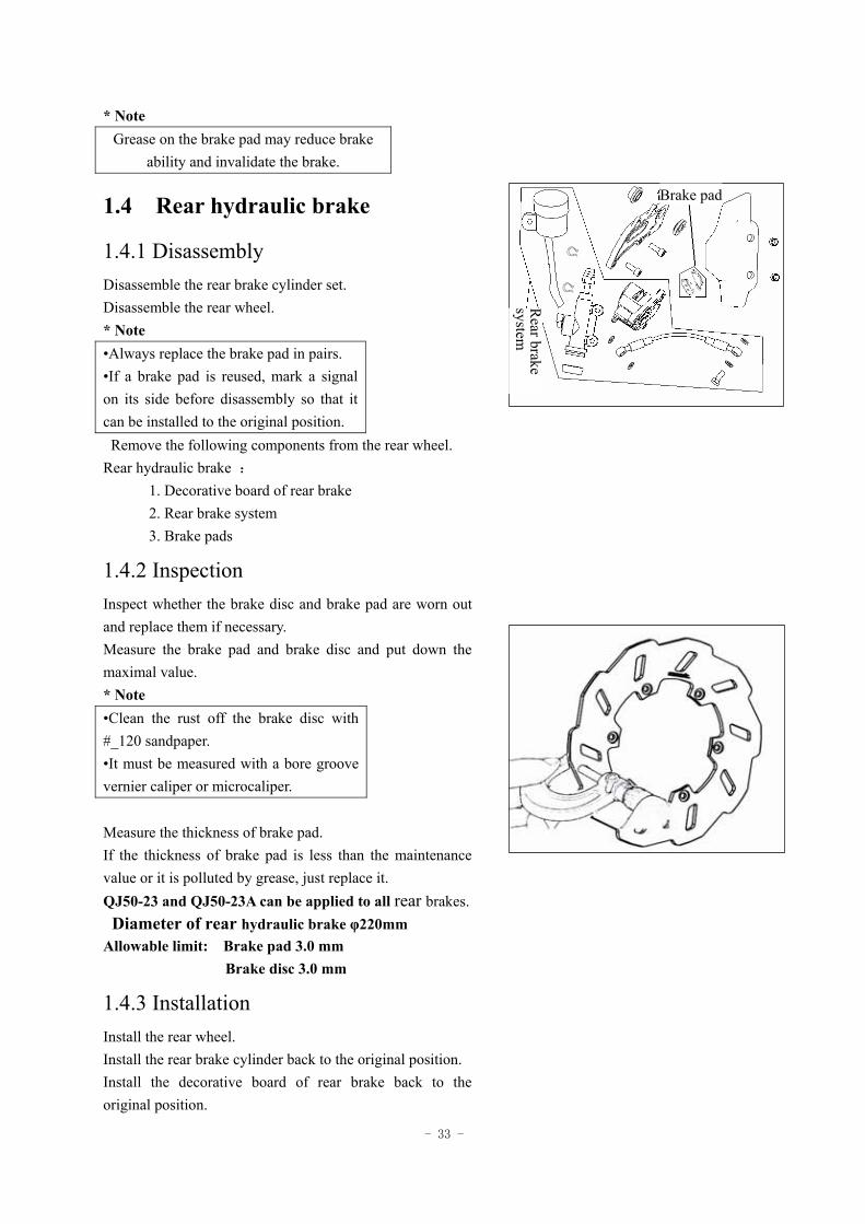
1.4 Rear hydraulic brake
1.4.1 Disassembly Disassemble the rear brake cylinder set. Disassemble the rear wheel. * Note •Always replace the brake pad in pairs. •If a brake pad is reused, mark a signal on its side before disassembly so that it can be installed to the original position. Remove the following components from the rear wheel. Rear hydraulic brake :
1. Decorative board of rear brake 2. Rear brake system 3. Brake pads
1.4.2 Inspection Inspect whether the brake disc and brake pad are worn out and replace them if necessary. Measure the brake pad and brake disc and put down the maximal value. * Note •Clean the rust off the brake disc with #_120 sandpaper. •It must be measured with a bore groove vernier caliper or microcaliper.
Measure the thickness of brake pad. If the thickness of brake pad is less than the maintenance value or it is polluted by grease, just replace it. QJ50-23 and QJ50-23A can be applied to all rear brakes. Diameter of rear hydraulic brake φ220mm Allowable limit: Brake pad 3.0 mm Brake disc 3.0 mm
1.4.3 Installation Install the rear wheel. Install the rear brake cylinder back to the original position. Install the decorative board of rear brake back to the original position.
Brake pad
Rear brake
system
- 34 -
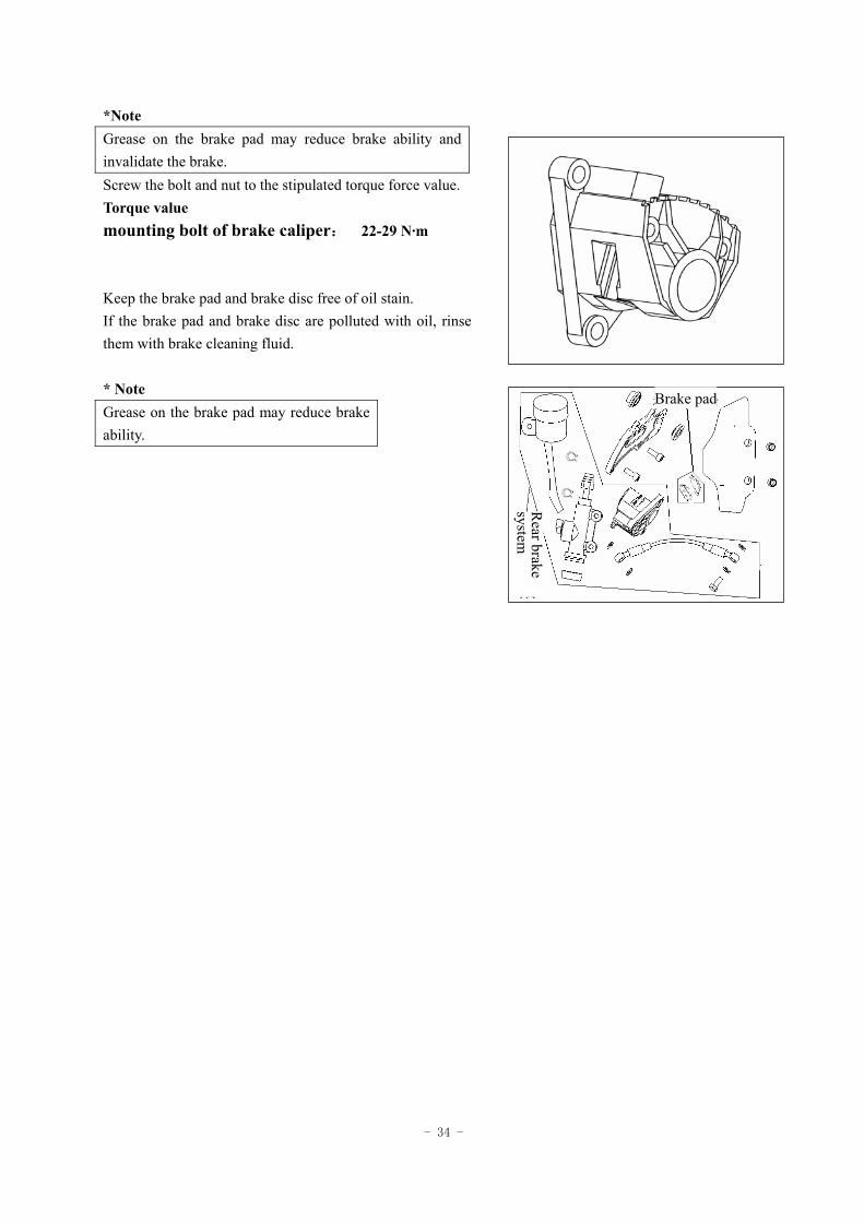
*Note Grease on the brake pad may reduce brake ability and invalidate the brake. Screw the bolt and nut to the stipulated torque force value. Torque value mounting bolt of brake caliper: 22-29 N·m Keep the brake pad and brake disc free of oil stain. If the brake pad and brake disc are polluted with oil, rinse them with brake cleaning fluid. * Note Grease on the brake pad may reduce brake ability.
Brake pad
Rear brake
system
- 35 -
air guide sleeveinstrum
ent support
right front upper board
right front lower board
right guard
right lower board
Connecting
board of
left and
right guard
Rear m
udguard I
front mudguard
inner rear
mudguard
Rear m
udguardII
leftguardstrip
rightguardstrip
downw
ard air sleeve
left front lower board
left front lower board
right fram
e guard
left fram
e guard
cushion lock
left rear board
- 36 -
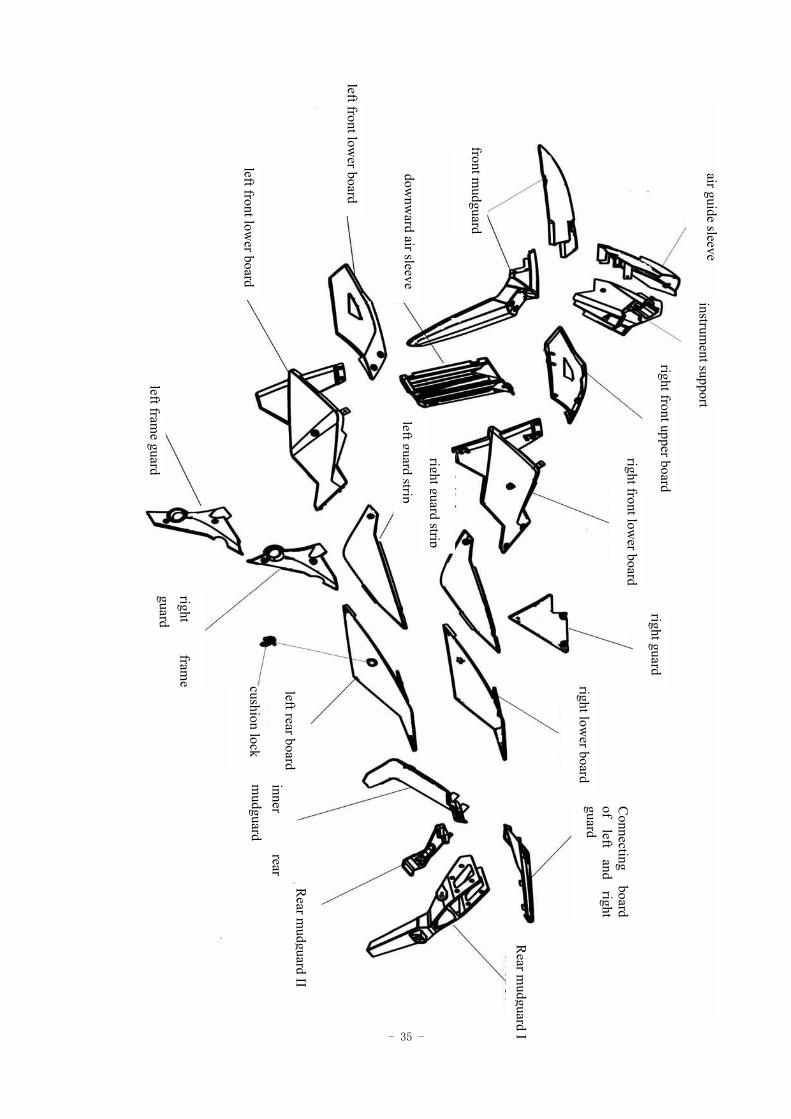
2 Body cover
Disassemble the motorcycle body according to the following order:
Rearview mirror → Air guide sleeve → Instrument support → Instrument → Front
mudguard →Front top guards
↓
Front bottom guards →cushion→left, right guard strip → Rear left and right
guard→ Connecting board of left and right guard
↓
→ Rear mudguard I→Rear mudguard II→Inner Rear mudguard → Left guard→Left and
right guard of the frame * Note Do not damage any body cover during installation or disassembly. Do not damage the knuckle on body cover during installation or disassembly. Align the panel and cover plate on the body cover with their own grooves. Correctly install the knuckle of each part in assembly. No spare parts could be damaged in installation of the cover.
- 37 -
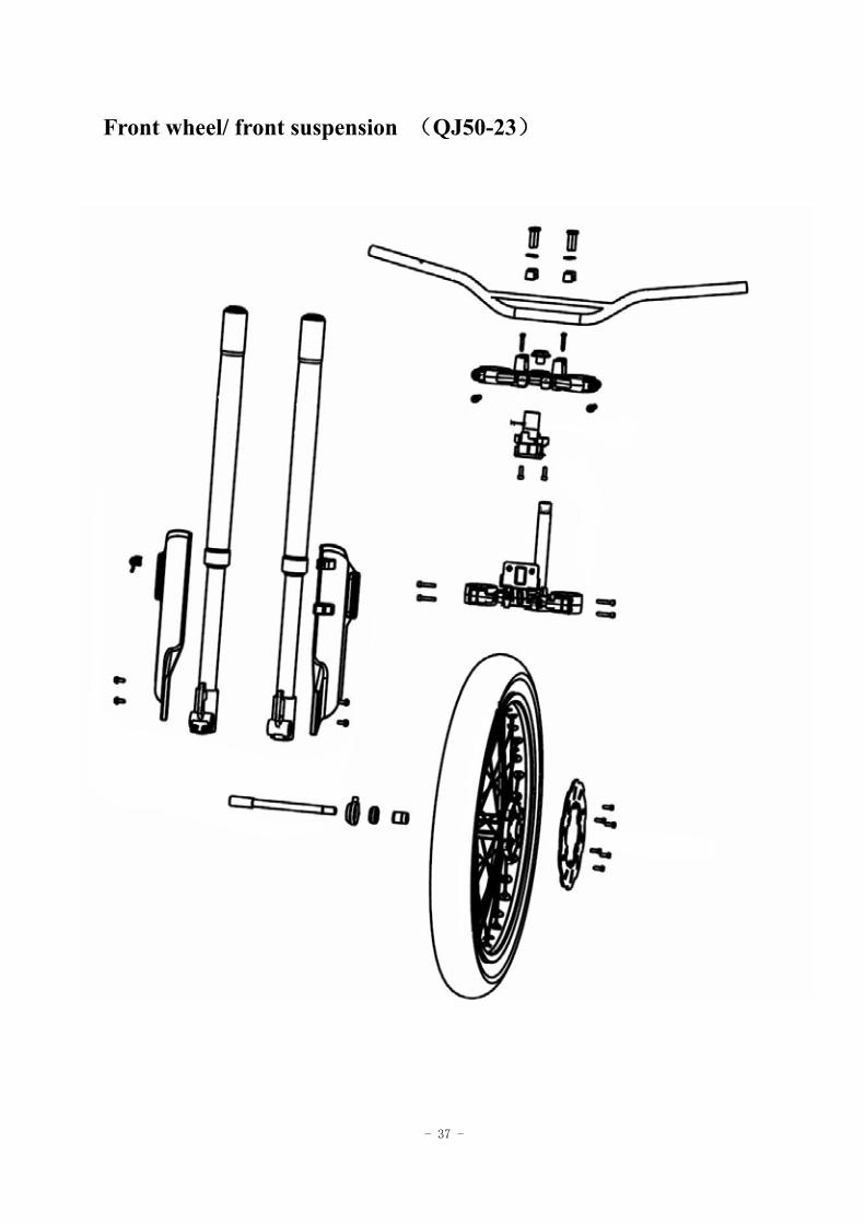
Front wheel/ front suspension (QJ50-23)
- 38 -
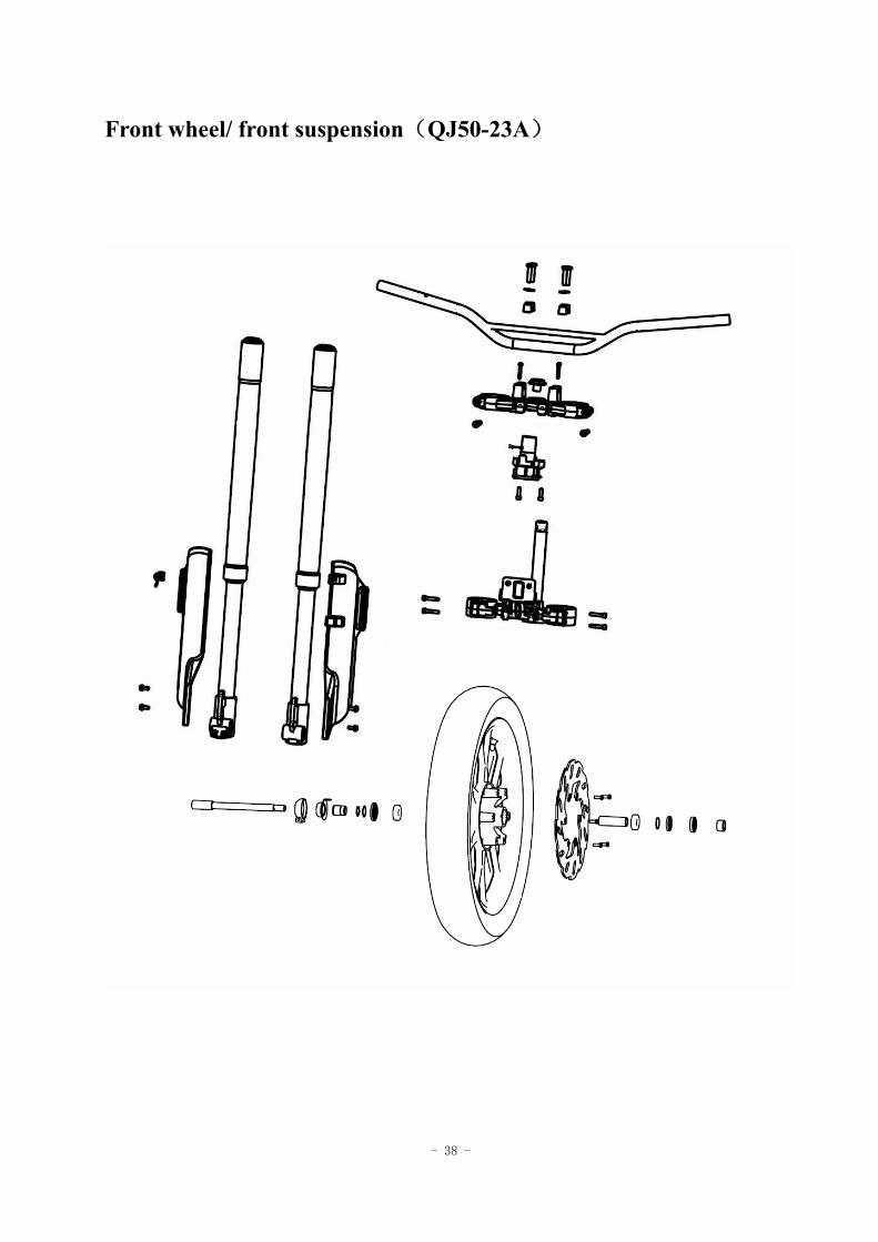
Front wheel/ front suspension(QJ50-23A)
- 39 -
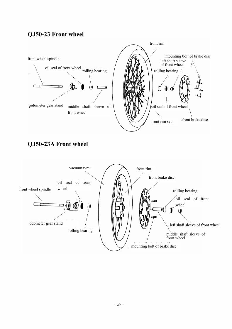
QJ50-23 Front wheel
QJ50-23A Front wheel
front rim
front wheel spindle
oil seal of front wheel rolling bearing
odometer gear stand middle shaft sleeve offront wheel
mounting bolt of brake disc left shaft sleeve of front wheel
rolling bearing
oil seal of front wheel
front rim set front brake disc
front rim
front wheel spindle
oil seal of front wheel
vacuum tyre
rolling bearing
odometer gear stand
middle shaft sleeve of front wheel
mounting bolt of brake disc
left shaft sleeve of front whee
front brake disc
oil seal of front wheel
rolling bearing
- 40 -
3 Front wheel/ front suspension
Preparation data -------------------------3.1
Fault diagnosis -------------------------3.2
Front wheel -------------------------3.3
Steering handle -------------------------3.4
Front fork -------------------------3.5
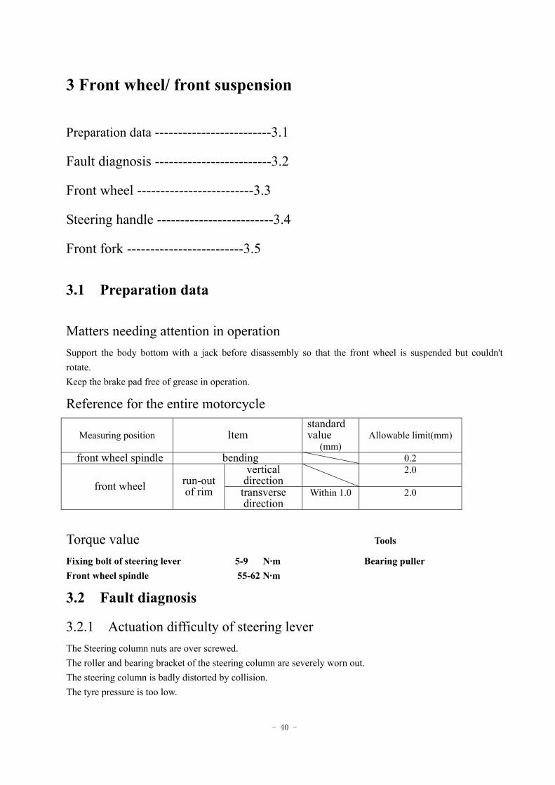
3.1 Preparation data
Matters needing attention in operation Support the body bottom with a jack before disassembly so that the front wheel is suspended but couldn't rotate. Keep the brake pad free of grease in operation.
Reference for the entire motorcycle
Measuring position Item standard value
(mm) Allowable limit(mm)
front wheel spindle bending 0.2 vertical
direction 2.0
front wheel run-out of rim transverse
direction Within 1.0 2.0
Torque value Tools
Fixing bolt of steering lever 5-9 N·m Bearing puller Front wheel spindle 55-62 N·m
3.2 Fault diagnosis
3.2.1 Actuation difficulty of steering lever The Steering column nuts are over screwed. The roller and bearing bracket of the steering column are severely worn out. The steering column is badly distorted by collision. The tyre pressure is too low.
- 41 -
3.2.2 Deviation of steering lever The left and right shock absorbers are not balanced. The front fork is bent. The front tire is bent and the tyre deviates. 3.2.3 Front wheel yawing The tyre is distorted. The front wheel bearing is loosened. The tyre is not good. 3.2.4 Front shock absorber too soft Elasticity fatigue of spring 3.2.5 Strange noise in front shock absorber Friction noise in shock absorber guard Loosening of bolts in rear shock absorber
3.3 Front wheel
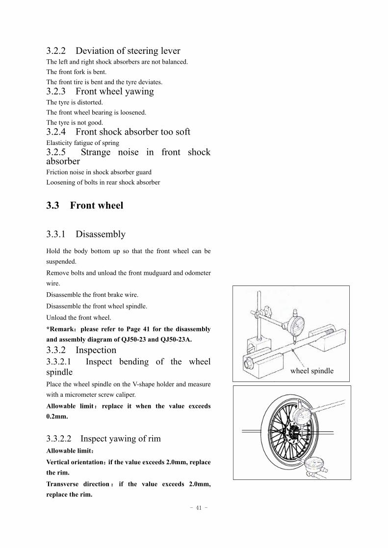
3.3.1 Disassembly
Hold the body bottom up so that the front wheel can be suspended.
Remove bolts and unload the front mudguard and odometer wire.
Disassemble the front brake wire.
Disassemble the front wheel spindle.
Unload the front wheel.
*Remark:please refer to Page 41 for the disassembly and assembly diagram of QJ50-23 and QJ50-23A.
3.3.2 Inspection 3.3.2.1 Inspect bending of the wheel spindle Place the wheel spindle on the V-shape holder and measure with a micrometer screw caliper.
Allowable limit:replace it when the value exceeds 0.2mm.
3.3.2.2 Inspect yawing of rim Allowable limit:
Vertical orientation:if the value exceeds 2.0mm, replace the rim.
Transverse direction : if the value exceeds 2.0mm, replace the rim.
wheel spindle
- 42 -
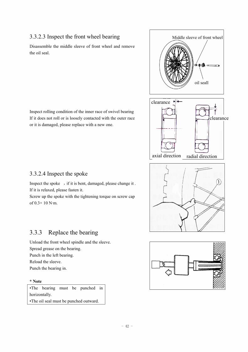
3.3.2.3 Inspect the front wheel bearing
Disassemble the middle sleeve of front wheel and remove the oil seal. Inspect rolling condition of the inner race of swivel bearing If it does not roll or is loosely contacted with the outer race or it is damaged, please replace with a new one.
3.3.2.4 Inspect the spoke Inspect the spoke,if it is bent, damaged, please change it . If it is relaxed, please fasten it. Screw up the spoke with the tightening torque on screw cap of 0.3× 10 N·m.
3.3.3 Replace the bearing Unload the front wheel spindle and the sleeve. Spread grease on the bearing. Punch in the left bearing. Reload the sleeve. Punch the bearing in. * Note •The bearing must be punched in horizontally. •The oil seal must be punched outward.
Middle sleeve of front wheel
oil seall
clearance
clearance
axial direction radial direction
- 43 -
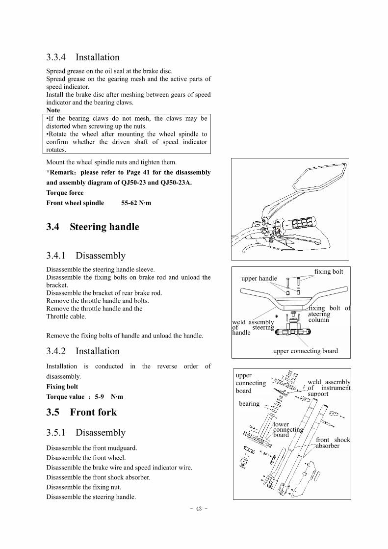
3.3.4 Installation
Spread grease on the oil seal at the brake disc. Spread grease on the gearing mesh and the active parts of speed indicator. Install the brake disc after meshing between gears of speed indicator and the bearing claws. Note •If the bearing claws do not mesh, the claws may be distorted when screwing up the nuts. •Rotate the wheel after mounting the wheel spindle to confirm whether the driven shaft of speed indicator rotates.
Mount the wheel spindle nuts and tighten them. *Remark:please refer to Page 41 for the disassembly and assembly diagram of QJ50-23 and QJ50-23A. Torque force Front wheel spindle 55-62 N·m
3.4 Steering handle
3.4.1 Disassembly Disassemble the steering handle sleeve. Disassemble the fixing bolts on brake rod and unload the bracket. Disassemble the bracket of rear brake rod. Remove the throttle handle and bolts. Remove the throttle handle and the Throttle cable. Remove the fixing bolts of handle and unload the handle.
3.4.2 Installation Installation is conducted in the reverse order of disassembly. Fixing bolt Torque value :5-9 N·m
3.5 Front fork
3.5.1 Disassembly Disassemble the front mudguard. Disassemble the front wheel. Disassemble the brake wire and speed indicator wire. Disassemble the front shock absorber. Disassemble the fixing nut. Disassemble the steering handle.
fixing boltupper handle
fixing bolt of steering column weld assembly
of steering handle
upper connecting board
upper connecting board
lower connecting board
bearing
weld assembly of instrument support
front shock absorber
- 44 -
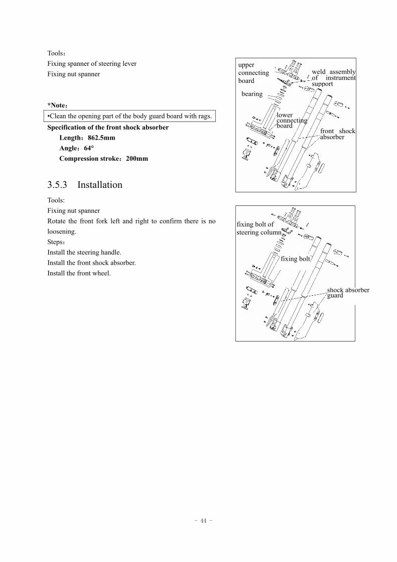
Tools: Fixing spanner of steering lever Fixing nut spanner *Note: •Clean the opening part of the body guard board with rags. Specification of the front shock absorber
Length:862.5mm Angle:64° Compression stroke:200mm
3.5.3 Installation Tools: Fixing nut spanner Rotate the front fork left and right to confirm there is no loosening. Steps: Install the steering handle. Install the front shock absorber. Install the front wheel.
upper connecting board
lower connecting board
bearing
weld assembly of instrument support
front shock absorber
fixing bolt of steering column
fixing bolt
shock absorberguard
- 45 -
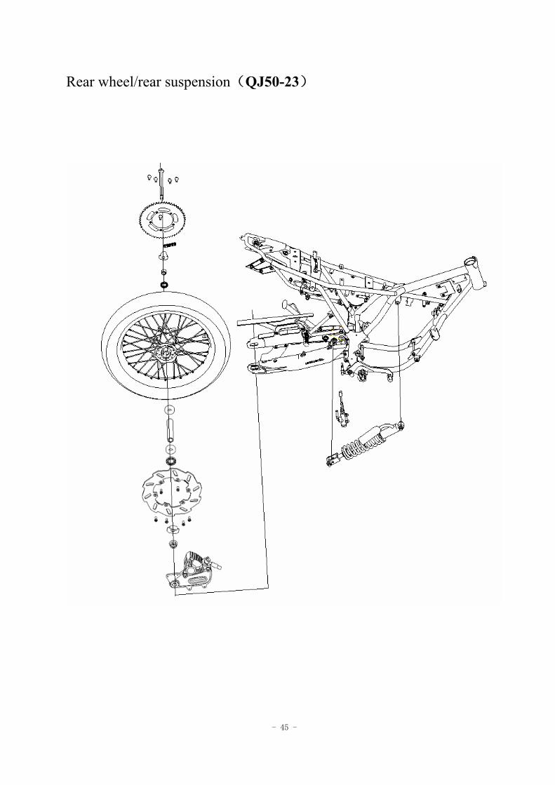
Rear wheel/rear suspension(QJ50-23)
- 46 -
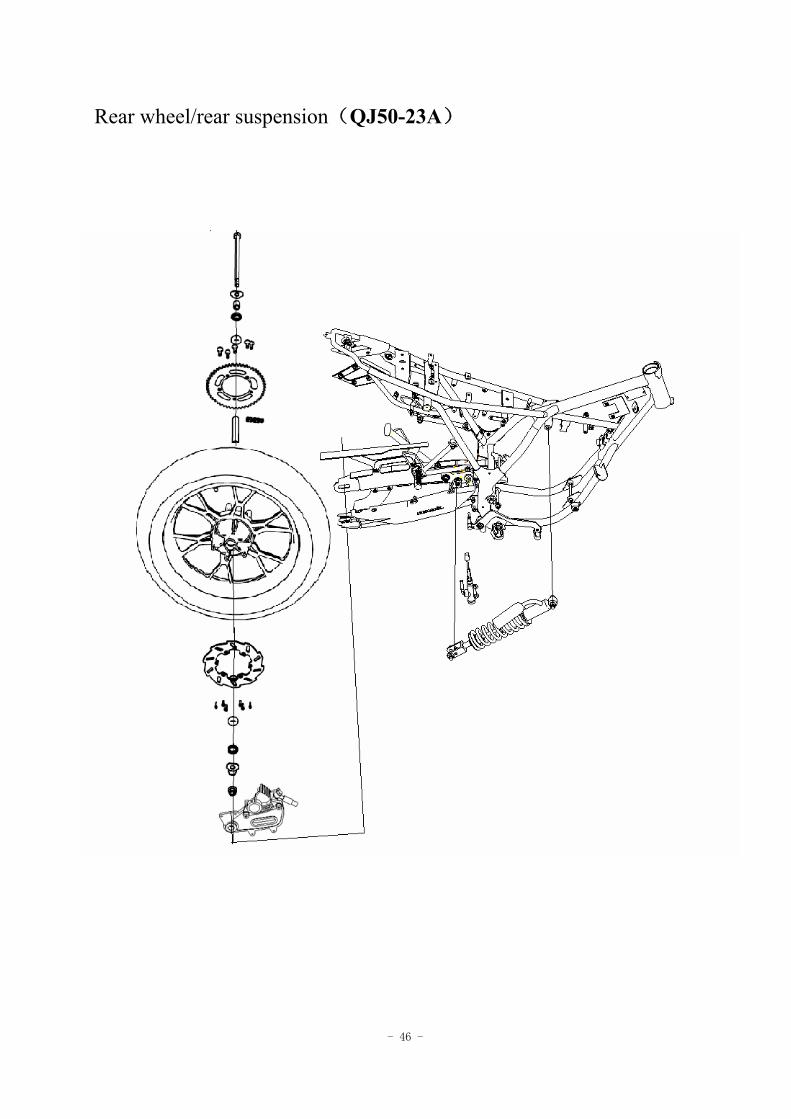
Rear wheel/rear suspension(QJ50-23A)
- 47 -
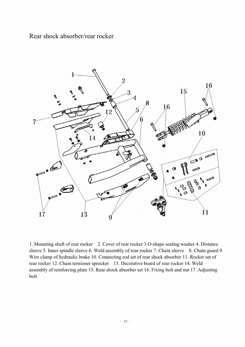
Rear shock absorber/rear rocker
1. Mounting shaft of rear rocker 2. Cover of rear rocker 3.O-shape sealing washer 4. Distance sleeve 5. Inner spindle sleeve 6. Weld assembly of rear rocker 7. Chain sleeve 8. Chain guard 9. Wire clamp of hydraulic brake 10. Connecting rod set of rear shock absorber 11. Rocker set of rear rocker 12. Chain tensioner sprocket 13. Decorative board of rear rocker 14. Weld assembly of reinforcing plate 15. Rear shock absorber set 16. Fixing bolt and nut 17. Adjusting bolt
- 48 -
4 Rear wheel/rear suspension
Preparation data -----------------4.1
Fault diagnosis -----------------4.2
Rear wheel -----------------4.3
Rear shock absorber/rear rocker ----------4.4
Driving chain -----------------4.5
4.1 Preparation data
Matters needing attention in operation There cannot be any oil stain stuck to the surface of the brake disc or brake pad.
Preparation reference
Item Standard value (mm) Allowable limit (mm) Vertical direction
2.0 Run-out of rear wheel
Transverse direction
2.0
Torque value Nut of Rear-wheel spindle 85-98 N·m Topping nut of the rear shock absorber 37-44 N·m Bottom nut of the rear shock absorber 37-44 N·m
4.2 Fault diagnosis
4.2.1 Run-out of rear wheel The rim is distorted. The tyre is not good.
4.2.2 Shock absorber too soft Elasticity fatigue of spring
- 49 -
4.3 Rear wheel
4.3.1 Disassembly Loosen the nuts on rear-wheel spindle. Remove the nuts on the rear-wheel spindle and the chain. Unload the rear-wheel spindle. Unload the rear-wheel.
4.3.2 Inspection Inspect the run-out of rear wheel. Allowable limit : Vertical direction :2.0mm or above. Transverse direction :2.0mm or above. When the run-out of rear wheel exceeds the allowable limit, the bearing of final drive shaft will be loosened, resulting in bending of bearing shafts. Replace the bearing after inspection.
4.3.3 Installation Install the rear wheel in the reverse order of disassembly and screw the spindle nut. Locknut of rear-wheel spindle Torque value :85-98 N·m
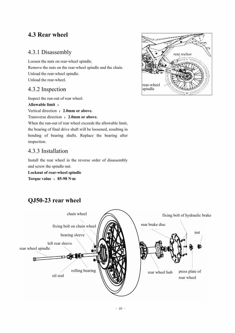
QJ50-23 rear wheel
rear rocker
rear-wheel spindle
chain wheel
fixing bolt on chain wheel
bearing sleeve
left rear sleeve rear wheel spindle
oil seal rolling bearing
rear brake disc
fixing bolt of hydraulic brake
nut
rear wheel hub press plate of rear wheel
- 50 -
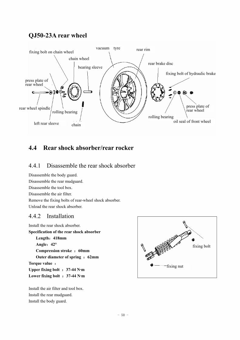
QJ50-23A rear wheel
4.4 Rear shock absorber/rear rocker
4.4.1 Disassemble the rear shock absorber Disassemble the body guard. Disassemble the rear mudguard. Disassemble the tool box. Disassemble the air filter. Remove the fixing bolts of rear-wheel shock absorber. Unload the rear shock absorber.
4.4.2 Installation Install the rear shock absorber. Specification of the rear shock absorber
Length:418mm Angle:42° Compression stroke :60mm Outer diameter of spring :62mm
Torque value : Upper fixing bolt :37-44 N·m Lower fixing bolt :37-44 N·m Install the air filter and tool box. Install the rear mudguard. Install the body guard.
fixing bolt on chain wheel
press plate of rear wheel
chain wheel
bearing sleeve
vacuum tyre rear rim
rear brake disc
fixing bolt of hydraulic brake
rolling bearing rolling bearing
oil seal of front wheel
press plate of rear wheel rear wheel spindle
left rear sleeve chain
fixing bolt
fixing nut
- 51 -
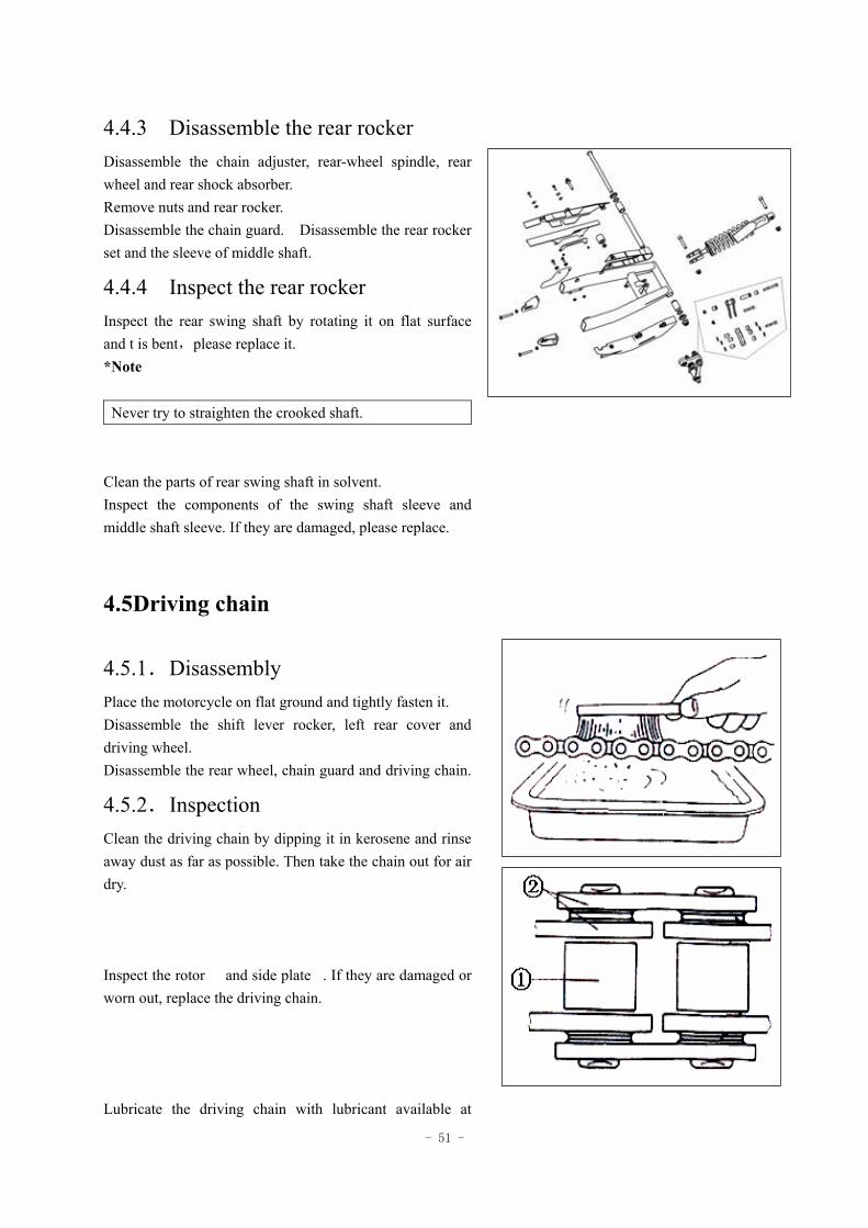
4.4.3 Disassemble the rear rocker Disassemble the chain adjuster, rear-wheel spindle, rear wheel and rear shock absorber. Remove nuts and rear rocker. Disassemble the chain guard. Disassemble the rear rocker set and the sleeve of middle shaft.
4.4.4 Inspect the rear rocker Inspect the rear swing shaft by rotating it on flat surface and t is bent,please replace it. *Note
Never try to straighten the crooked shaft. Clean the parts of rear swing shaft in solvent. Inspect the components of the swing shaft sleeve and middle shaft sleeve. If they are damaged, please replace.
4.5Driving chain
4.5.1.Disassembly Place the motorcycle on flat ground and tightly fasten it. Disassemble the shift lever rocker, left rear cover and driving wheel. Disassemble the rear wheel, chain guard and driving chain.
4.5.2.Inspection Clean the driving chain by dipping it in kerosene and rinse away dust as far as possible. Then take the chain out for air dry.
Inspect the rotor and side plate. If they are damaged or worn out, replace the driving chain.
Lubricate the driving chain with lubricant available at
- 52 -
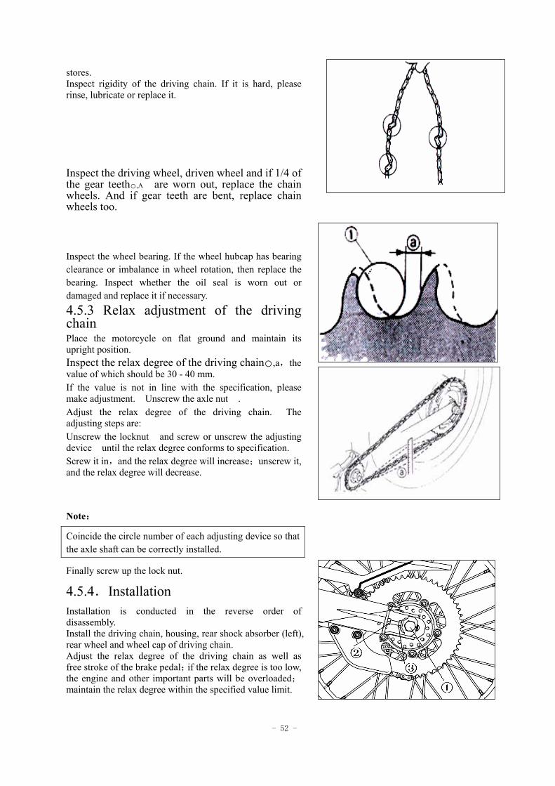
stores. Inspect rigidity of the driving chain. If it is hard, please rinse, lubricate or replace it. Inspect the driving wheel, driven wheel and if 1/4 of the gear teeth,A are worn out, replace the chain wheels. And if gear teeth are bent, replace chain wheels too. Inspect the wheel bearing. If the wheel hubcap has bearing clearance or imbalance in wheel rotation, then replace the bearing. Inspect whether the oil seal is worn out or damaged and replace it if necessary. 4.5.3 Relax adjustment of the driving chain Place the motorcycle on flat ground and maintain its upright position. Inspect the relax degree of the driving chain,a,the value of which should be 30 - 40 mm. If the value is not in line with the specification, please make adjustment. Unscrew the axle nut . Adjust the relax degree of the driving chain. The adjusting steps are: Unscrew the locknut and screw or unscrew the adjusting device until the relax degree conforms to specification. Screw it in,and the relax degree will increase;unscrew it, and the relax degree will decrease.
Note:
Finally screw up the lock nut.
4.5.4.Installation Installation is conducted in the reverse order of disassembly. Install the driving chain, housing, rear shock absorber (left), rear wheel and wheel cap of driving chain. Adjust the relax degree of the driving chain as well as free stroke of the brake pedal;if the relax degree is too low, the engine and other important parts will be overloaded;maintain the relax degree within the specified value limit.
Coincide the circle number of each adjusting device so that the axle shaft can be correctly installed.
- 53 -
- 54 -
5 Battery/charging system
Preparation data -------------5.1 Fault diagnosis -------------5.2 Battery ---------------5.3 Charging system -------------5.4 Voltage and current regulator -------5.5 Charge coil of the alternator ---5.6 Illuminating coil of alternator ---5.7 Disassembly of alternator -----5.8
5.1 Preparation data
Matters needing attention in operation * Note 1. The battery can be charged and discharged over again. If the battery is unused after discharge, the service life will shorten and the performance will degrade. Generally, performance of the battery used for 2 or 3 years will degrade. Such battery(capacity declined)may restore its voltage after charging but the voltage will drop off rapidly when loaded. 2.Surcharge of battery:generally surcharge can be observed from the battery proper. If the battery is cut short inside, no voltage can be tested at the terminal of the battery or the voltage is very low. Invalidation of the regulator:the battery will have too high voltage, which may shorten its service life. 3. Long rest of the battery will result in self discharge and the electric capacity will reduce, therefore, it must be charged every 3 months. 5. Inspect the charging system in accordance with the order stipulated in the fault diagnosis table. 6. If there is electric current passes through an electrical unit, do not disassemble the connector, otherwise, overtension will occur which can damage the electronic parts inside the voltage regulator. The main switch must be pushed to "off" before any operation. 7. Maintenance free(dry charged type)battery does not need inspection, replenish of electrolyte solution or distilled water. 8. Inspect the entire power load. 9. Emergency charging cannot be used except in contingency situations. 10.In emergency charging of the battery,it must be unloaded from the motorcycle before charging. 11. Please do not use liquid type battery when exchanging batterys. 12. A voltage meter must be used when inspecting the charging conditions.
- 55 -
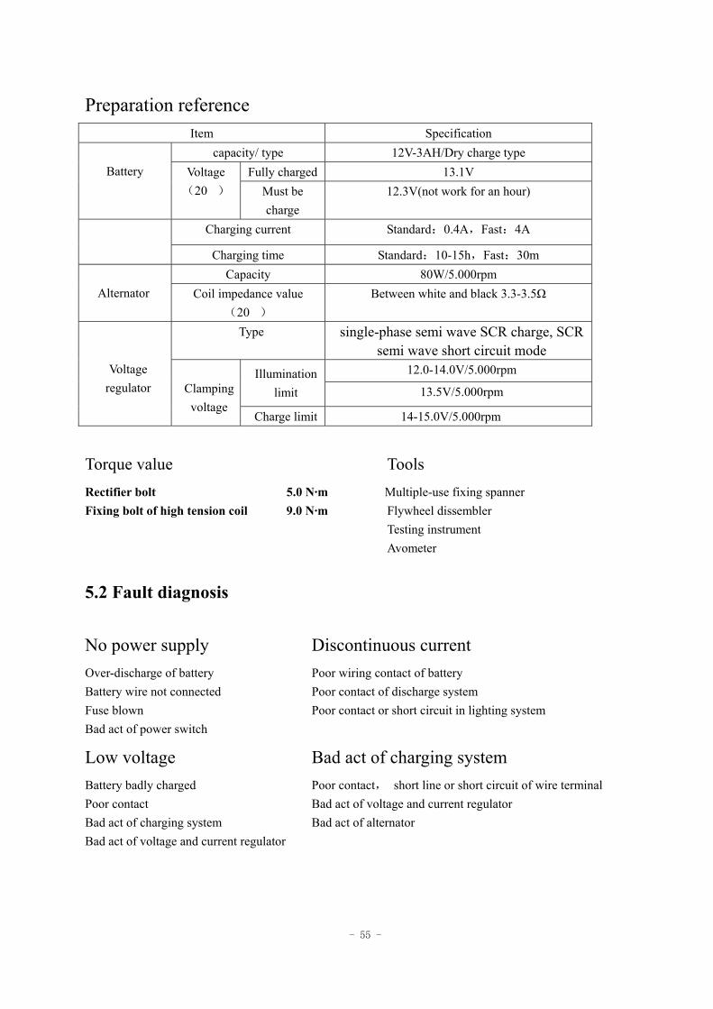
Preparation reference Item Specification
capacity/ type 12V-3AH/Dry charge type Fully charged 13.1V
Battery Voltage
(20) Must be charge
12.3V(not work for an hour)
Charging current Standard:0.4A,Fast:4A
Charging time Standard:10-15h,Fast:30m Capacity 80W/5.000rpm
Alternator Coil impedance value (20)
Between white and black 3.3-3.5Ω
Type single-phase semi wave SCR charge, SCR semi wave short circuit mode
12.0-14.0V/5.000rpm Illumination limit 13.5V/5.000rpm
Voltage regulator
Clamping voltage
Charge limit 14-15.0V/5.000rpm
Torque value Tools Rectifier bolt 5.0 N·m Multiple-use fixing spanner Fixing bolt of high tension coil 9.0 N·m Flywheel dissembler
Testing instrument Avometer
5.2 Fault diagnosis
No power supply Discontinuous current Over-discharge of battery Poor wiring contact of battery Battery wire not connected Poor contact of discharge system Fuse blown Poor contact or short circuit in lighting system Bad act of power switch
Low voltage Bad act of charging system Battery badly charged Poor contact, short line or short circuit of wire terminal Poor contact Bad act of voltage and current regulator Bad act of charging system Bad act of alternator Bad act of voltage and current regulator
- 56 -
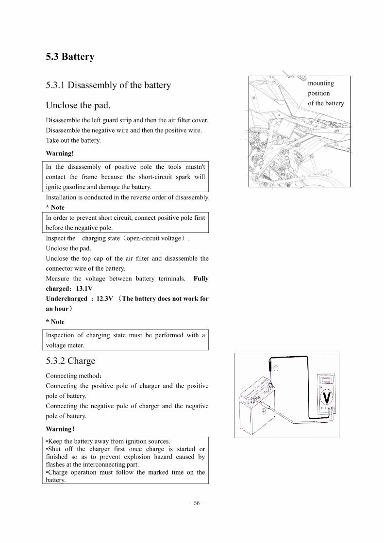
5.3 Battery
5.3.1 Disassembly of the battery
Unclose the pad. Disassemble the left guard strip and then the air filter cover. Disassemble the negative wire and then the positive wire. Take out the battery.
Warning!
In the disassembly of positive pole the tools mustn't contact the frame because the short-circuit spark will ignite gasoline and damage the battery. Installation is conducted in the reverse order of disassembly. * Note In order to prevent short circuit, connect positive pole first before the negative pole. Inspect the charging state(open-circuit voltage). Unclose the pad. Unclose the top cap of the air filter and disassemble the connector wire of the battery. Measure the voltage between battery terminals. Fully charged:13.1V Undercharged :12.3V (The battery does not work for an hour)
* Note
Inspection of charging state must be performed with a voltage meter.
5.3.2 Charge Connecting method: Connecting the positive pole of charger and the positive pole of battery. Connecting the negative pole of charger and the negative pole of battery.
Warning!
•Keep the battery away from ignition sources. •Shut off the charger first once charge is started or finished so as to prevent explosion hazard caused by flashes at the interconnecting part. •Charge operation must follow the marked time on the battery.
电瓶的安
装位置
mounting position of the battery
- 57 -
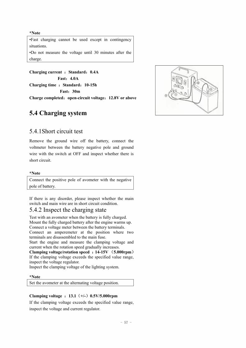
*Note •Fast charging cannot be used except in contingency situations. •Do not measure the voltage until 30 minutes after the charge. Charging current :Standard:0.4A Fast:4.0A Charging time :Standard:10-15h Fast:30m Charge completed:open-circuit voltage:12.8V or above
5.4 Charging system
5.4.1Short circuit test Remove the ground wire off the battery, connect the voltmeter between the battery negative pole and ground wire with the switch at OFF and inspect whether there is short circuit. *Note Connect the positive pole of avometer with the negative pole of battery. If there is any disorder, please inspect whether the main switch and main wire are in short circuit condition. 5.4.2 Inspect the charging state Test with an avometer when the battery is fully charged. Mount the fully charged battery after the engine warms up. Connect a voltage meter between the battery terminals. Connect an amperemeter at the position where two terminals are disassembled to the main fuse. Start the engine and measure the clamping voltage and current when the rotation speed gradually increases. Clamping voltage/rotation speed :14-15V (5.000rpm) If the clamping voltage exceeds the specified value range, inspect the voltage regulator. Inspect the clamping voltage of the lighting system. *Note Set the avometer at the alternating voltage position. Clamping voltage :13.1(+/-)0.5V/5.000rpm If the clamping voltage exceeds the specified value range, inspect the voltage and current regulator.
- 58 -
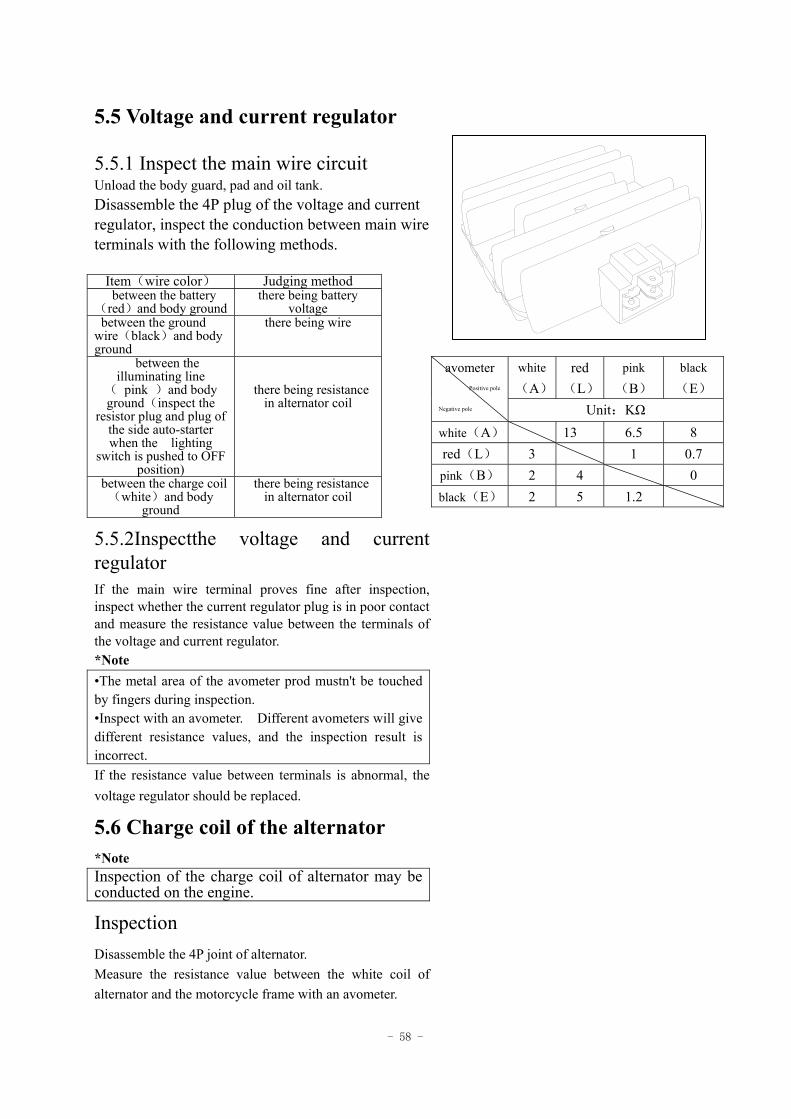
5.5 Voltage and current regulator
5.5.1 Inspect the main wire circuit Unload the body guard, pad and oil tank. Disassemble the 4P plug of the voltage and current regulator, inspect the conduction between main wire terminals with the following methods.
Item(wire color) Judging method between the battery
(red)and body ground there being battery
voltage between the ground wire(black)and body ground
there being wire
between the illuminating line
( pink )and body ground(inspect the
resistor plug and plug of the side auto-starter when the lighting
switch is pushed to OFF position)
there being resistance in alternator coil
between the charge coil(white)and body
ground
there being resistance in alternator coil
5.5.2Inspectthe voltage and current regulator If the main wire terminal proves fine after inspection, inspect whether the current regulator plug is in poor contact and measure the resistance value between the terminals of the voltage and current regulator. *Note •The metal area of the avometer prod mustn't be touched by fingers during inspection. •Inspect with an avometer. Different avometers will give different resistance values, and the inspection result is incorrect. If the resistance value between terminals is abnormal, the voltage regulator should be replaced.
5.6 Charge coil of the alternator *Note Inspection of the charge coil of alternator may be conducted on the engine.
Inspection Disassemble the 4P joint of alternator. Measure the resistance value between the white coil of alternator and the motorcycle frame with an avometer.
white
(A)
red (L)
pink
(B) black
(E) avometer
Positive pole
Negative pole Unit:KΩ white(A) 13 6.5 8 red(L) 3 1 0.7 pink(B) 2 4 0 black(E) 2 5 1.2
- 59 -
Standard value :0.6-1Ω(20) If the measured value exceeds the standard value, replace the alternator coil.
5.7 Illuminating coil of alternator
*Note Inspection of the illuminating coil of alternator can be conducted on the engine.
Inspection Disassemble the 4P joint of alternator. Measure the resistance value between the white coil of alternator and the body ground with an avometer. Standard value :0.6-1Ω(20) If the measured value exceeds the standard value, replace the alternator coil.
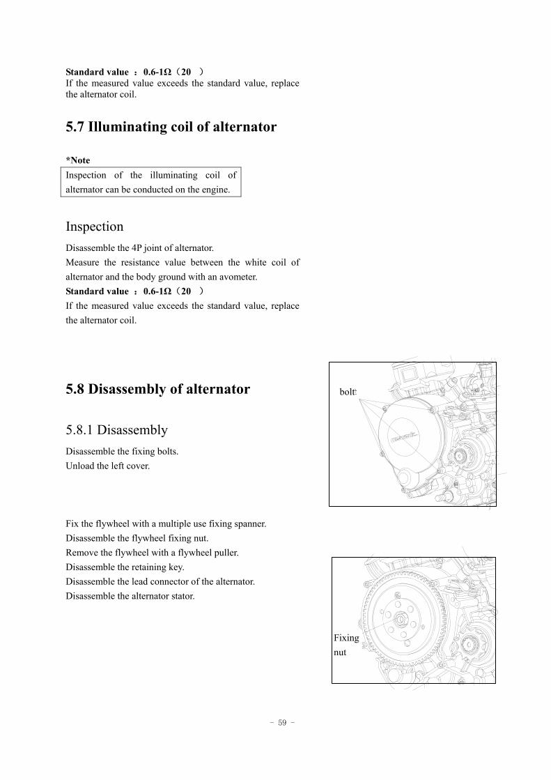
5.8 Disassembly of alternator
5.8.1 Disassembly Disassemble the fixing bolts. Unload the left cover. Fix the flywheel with a multiple use fixing spanner. Disassemble the flywheel fixing nut. Remove the flywheel with a flywheel puller. Disassemble the retaining key. Disassemble the lead connector of the alternator. Disassemble the alternator stator.
螺栓bolt
固定
螺母
Fixingnut
- 60 -
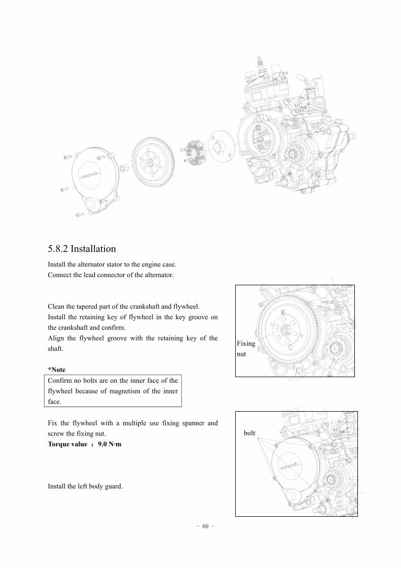
5.8.2 Installation
Install the alternator stator to the engine case. Connect the lead connector of the alternator. Clean the tapered part of the crankshaft and flywheel. Install the retaining key of flywheel in the key groove on the crankshaft and confirm. Align the flywheel groove with the retaining key of the shaft. *Note Confirm no bolts are on the inner face of the flywheel because of magnetism of the inner face. Fix the flywheel with a multiple use fixing spanner and screw the fixing nut. Torque value :9.0 N·m Install the left body guard.
螺栓
固定
螺母
Fixingnut
bolt
- 61 -
BATTERY
MAIN SW
FUSE 10A
W/G
SPARK PLUG
IGNITION COIL
BB/W W/GBL/W R/W
W
W/GBL/W B
MAGNETO
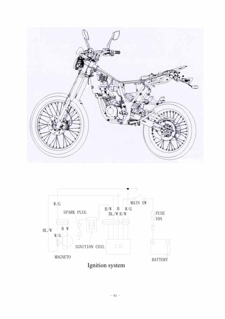
点火系统Ignition system
- 62 -
6 Ignition system
Preparation data ---------------------- 6.1 Ignition coil -------------------- 6.5 Fault diagnosis ----------------------- 6.2 Trigger -------------------------- 6.6 Ignition system inspection --------- 6.3 Charge coil --------------------- 6.7 CDI group ---------------------------- 6.4
6.1 Preparation data
Matters needing attention in operation 1. Inspect the ignition system in accordance with the order stipulated in the fault diagnosis table. 2. The ignition system is an electronic auto-advance device integrated in the CDI group, therefore the ignition time needs no adjustment. 3. Inspect the ignition system in accordance with the order stipulated in the fault diagnosis table. 4.Take particular care in disassembly that the CDI group of ignition system should not fall off and drop down or should not stricken with might(which is the main cause of fault) 5. Bad socket contact is the main cause of the ignition system fault, so inspect whether the joint of each part is in poor contact or not. 6. Inspect whether the spark plug is utilized at a proper thermal value. Improper spark plug may lead to unsmooth operation of engine or burn-out of the spark plug. 7. Inspection in the chapter is based on explanation of peak voltage and the judgment whether the resistance value of ignition coil is OK or not according to records after the inspection. 8. Inspection of the main switch should be performed in accordance with the conduction table. 9. The disassembly of the alternator and stator should be conducted in accordance with the disassembly explanation.
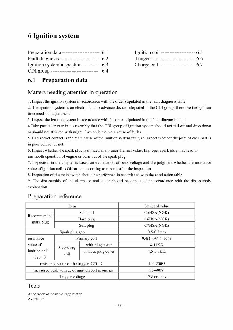
Preparation reference Item Standard value
Standard C5HSA(NGK) Hard plug C6HSA(NGK)
Recommended spark plug
Soft plug C7HSA(NGK) Spark plug gap 0.5-0.7mm
Primary coil 0.4Ω(+/-)10% with plug cover 8-11KΩ
resistance value of ignition coil
(20)
Secondary coil
without plug cover 4.5-5.5KΩ
resistance value of the trigger(20) 100-200Ω measured peak voltage of ignition coil at one go 95-400V
Trigger voltage 1.7V or above
Tools Accessory of peak voltage meter Avometer
- 63 -
6.2 Fault diagnosis
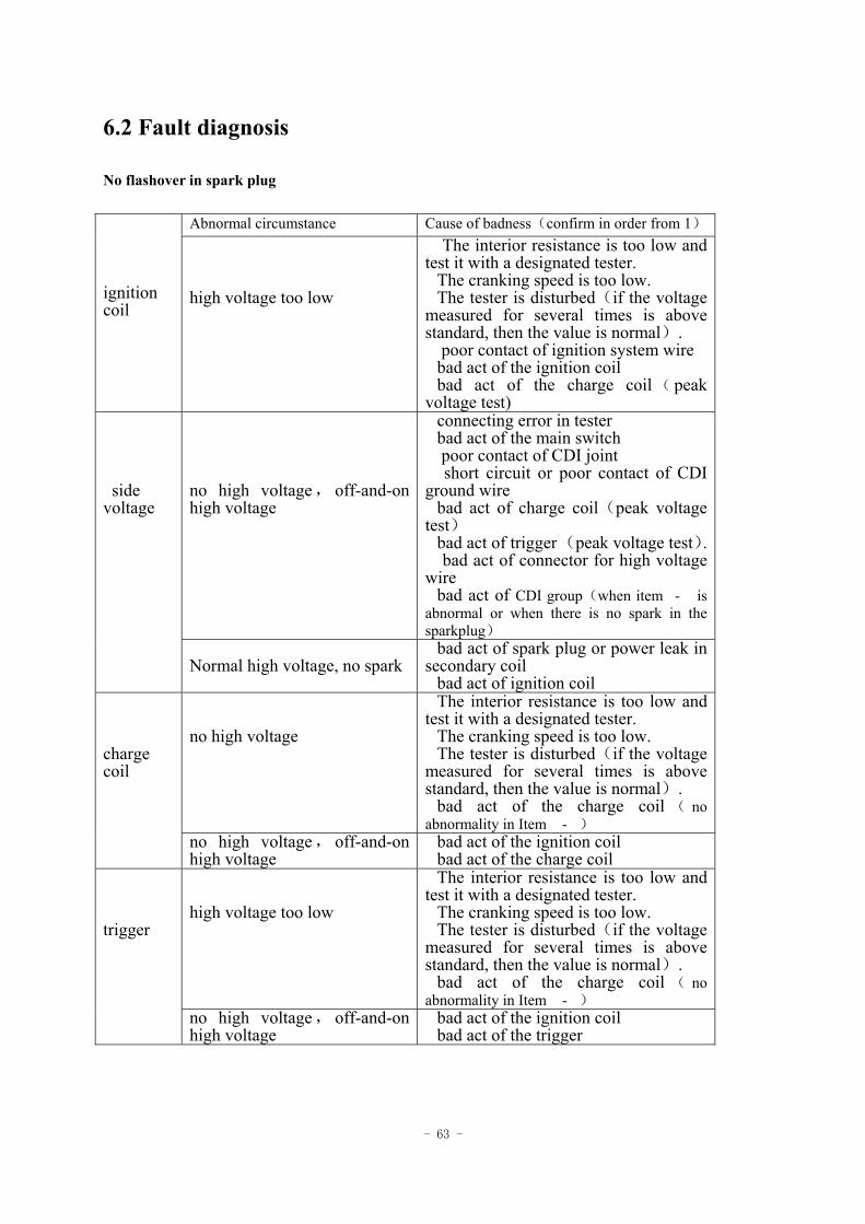
No flashover in spark plug
Abnormal circumstance Cause of badness(confirm in order from 1) ignition coil
high voltage too low
The interior resistance is too low and test it with a designated tester. The cranking speed is too low. The tester is disturbed(if the voltage measured for several times is above standard, then the value is normal). poor contact of ignition system wire bad act of the ignition coil bad act of the charge coil ( peak voltage test)
no high voltage,off-and-on high voltage
connecting error in tester bad act of the main switch poor contact of CDI joint short circuit or poor contact of CDI ground wire bad act of charge coil(peak voltage test) bad act of trigger (peak voltage test). bad act of connector for high voltage wire bad act of CDI group(when item- is abnormal or when there is no spark in the sparkplug)
side voltage
Normal high voltage, no spark bad act of spark plug or power leak in secondary coil bad act of ignition coil
no high voltage
The interior resistance is too low and test it with a designated tester. The cranking speed is too low. The tester is disturbed(if the voltage measured for several times is above standard, then the value is normal). bad act of the charge coil ( no abnormality in Item -)
charge coil
no high voltage,off-and-on high voltage
bad act of the ignition coil bad act of the charge coil
high voltage too low
The interior resistance is too low and test it with a designated tester. The cranking speed is too low. The tester is disturbed(if the voltage measured for several times is above standard, then the value is normal). bad act of the charge coil ( no abnormality in Item -)
trigger
no high voltage,off-and-on high voltage
bad act of the ignition coil bad act of the trigger
- 64 -
6.3 Ignition system inspection
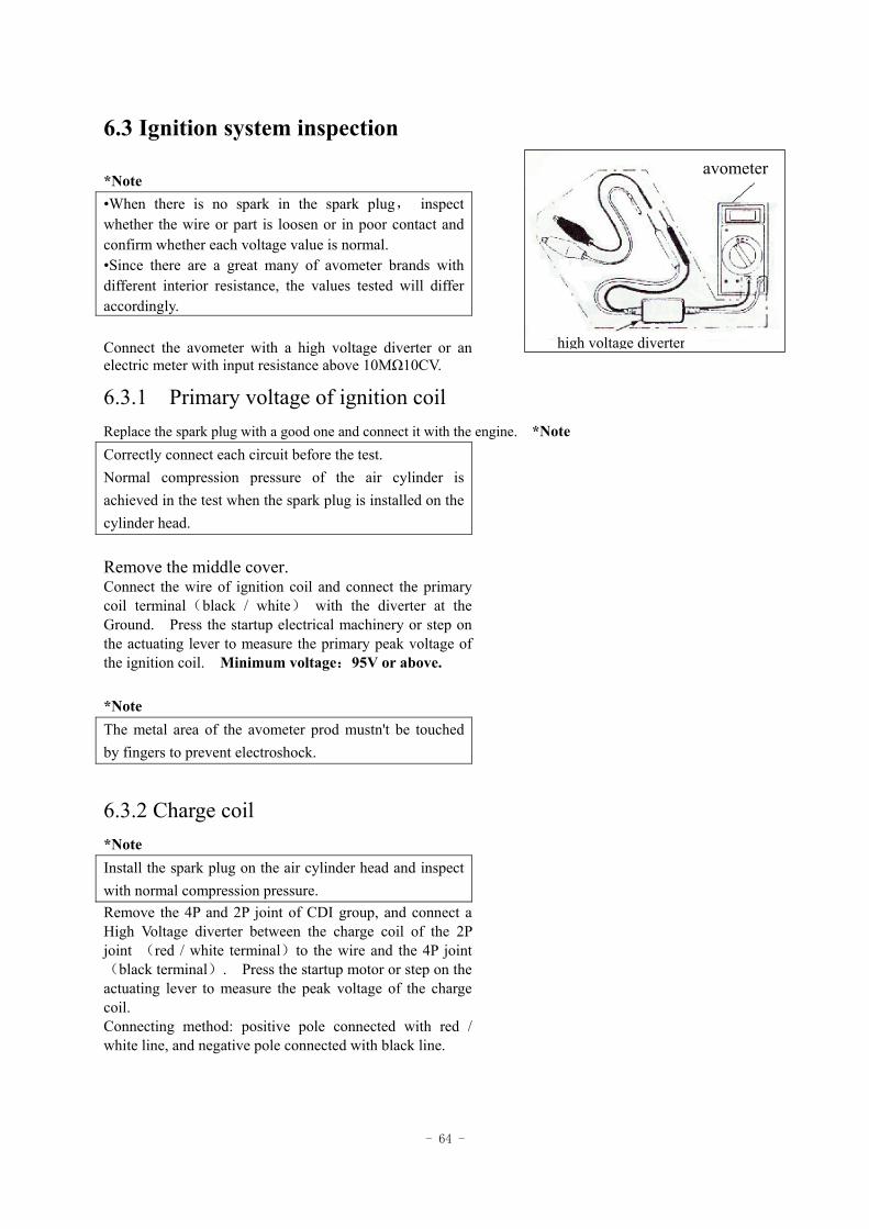
*Note •When there is no spark in the spark plug, inspect whether the wire or part is loosen or in poor contact and confirm whether each voltage value is normal. •Since there are a great many of avometer brands with different interior resistance, the values tested will differ accordingly. Connect the avometer with a high voltage diverter or an electric meter with input resistance above 10MΩ10CV.
6.3.1 Primary voltage of ignition coil Replace the spark plug with a good one and connect it with the engine. *Note Correctly connect each circuit before the test. Normal compression pressure of the air cylinder is achieved in the test when the spark plug is installed on the cylinder head. Remove the middle cover. Connect the wire of ignition coil and connect the primary coil terminal(black / white) with the diverter at the Ground. Press the startup electrical machinery or step on the actuating lever to measure the primary peak voltage of the ignition coil. Minimum voltage:95V or above. *Note The metal area of the avometer prod mustn't be touched by fingers to prevent electroshock.
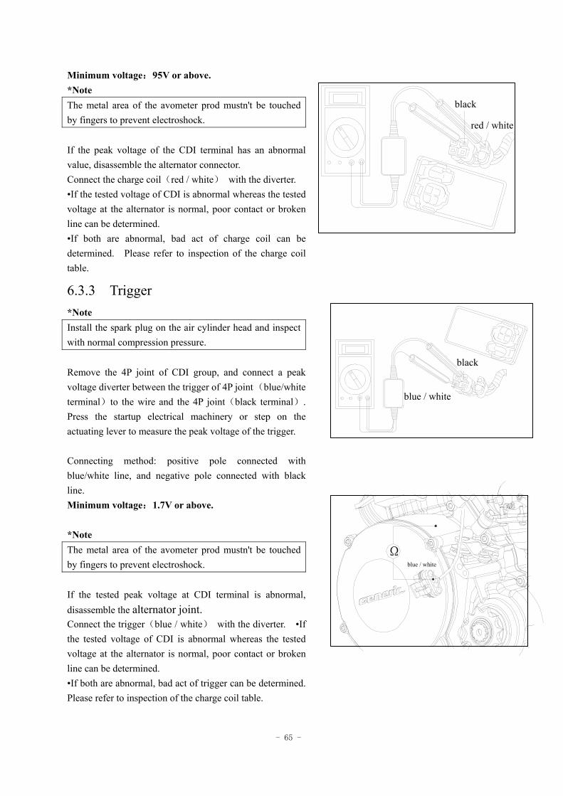
6.3.2 Charge coil *Note Install the spark plug on the air cylinder head and inspect with normal compression pressure. Remove the 4P and 2P joint of CDI group, and connect a High Voltage diverter between the charge coil of the 2P joint (red / white terminal)to the wire and the 4P joint(black terminal). Press the startup motor or step on the actuating lever to measure the peak voltage of the charge coil. Connecting method: positive pole connected with red / white line, and negative pole connected with black line.
avometer
high voltage diverter
- 65 -
Minimum voltage:95V or above. *Note The metal area of the avometer prod mustn't be touched by fingers to prevent electroshock. If the peak voltage of the CDI terminal has an abnormal value, disassemble the alternator connector. Connect the charge coil(red / white) with the diverter. •If the tested voltage of CDI is abnormal whereas the tested voltage at the alternator is normal, poor contact or broken line can be determined. •If both are abnormal, bad act of charge coil can be determined. Please refer to inspection of the charge coil table.
6.3.3 Trigger *Note Install the spark plug on the air cylinder head and inspect with normal compression pressure. Remove the 4P joint of CDI group, and connect a peak voltage diverter between the trigger of 4P joint (blue/white terminal)to the wire and the 4P joint(black terminal). Press the startup electrical machinery or step on the actuating lever to measure the peak voltage of the trigger. Connecting method: positive pole connected with blue/white line, and negative pole connected with black line. Minimum voltage:1.7V or above. *Note The metal area of the avometer prod mustn't be touched by fingers to prevent electroshock. If the tested peak voltage at CDI terminal is abnormal, disassemble the alternator joint. Connect the trigger(blue / white) with the diverter. •If the tested voltage of CDI is abnormal whereas the tested voltage at the alternator is normal, poor contact or broken line can be determined. •If both are abnormal, bad act of trigger can be determined. Please refer to inspection of the charge coil table.
黑
红/白
black
red / white
Ω蓝\白
黑
蓝/白
black
blue / white
blue / white
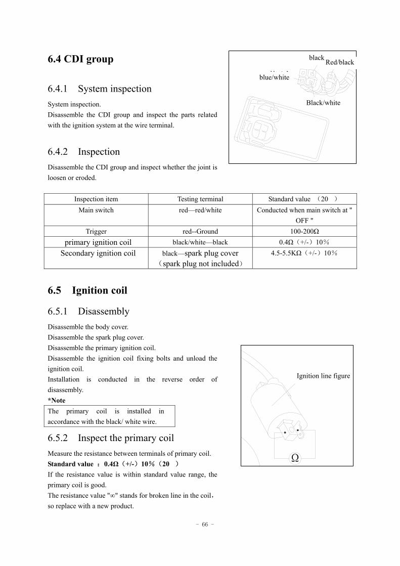
- 66 -
6.4 CDI group
6.4.1 System inspection System inspection. Disassemble the CDI group and inspect the parts related with the ignition system at the wire terminal.
6.4.2 Inspection Disassemble the CDI group and inspect whether the joint is loosen or eroded.
Inspection item Testing terminal Standard value (20) Main switch red—red/white Conducted when main switch at "
OFF " Trigger red--Ground 100-200Ω
primary ignition coil black/white—black 0.4Ω(+/-)10% Secondary ignition coil black—spark plug cover
(spark plug not included) 4.5-5.5KΩ(+/-)10%
6.5 Ignition coil
6.5.1 Disassembly Disassemble the body cover. Disassemble the spark plug cover. Disassemble the primary ignition coil. Disassemble the ignition coil fixing bolts and unload the ignition coil. Installation is conducted in the reverse order of disassembly. *Note The primary coil is installed in accordance with the black/ white wire.
6.5.2 Inspect the primary coil Measure the resistance between terminals of primary coil. Standard value :0.4Ω(+/-)10%(20) If the resistance value is within standard value range, the primary coil is good. The resistance value "∞" stands for broken line in the coil,so replace with a new product.
红/黑
蓝/白
黑
黑/白
black Red/black
Black/white
blue/white
Ω
点火线图Ignition line figure
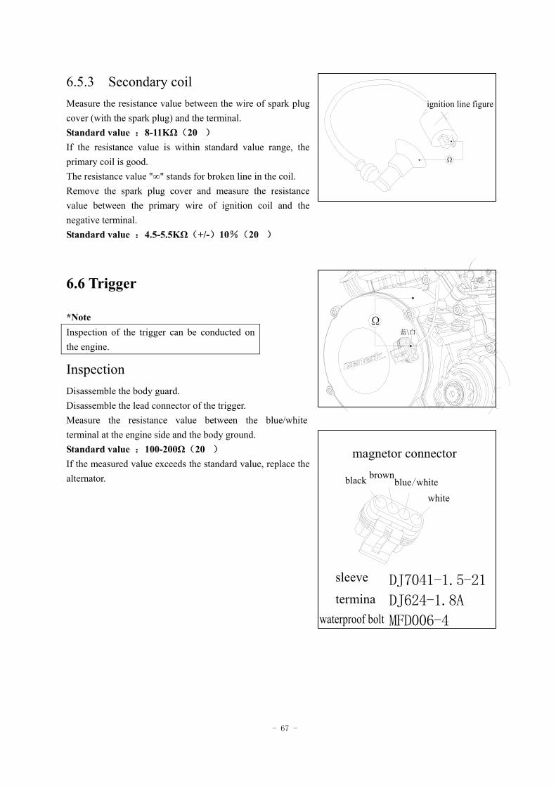
- 67 -
6.5.3 Secondary coil Measure the resistance value between the wire of spark plug cover (with the spark plug) and the terminal. Standard value :8-11KΩ(20) If the resistance value is within standard value range, the primary coil is good. The resistance value "∞" stands for broken line in the coil. Remove the spark plug cover and measure the resistance value between the primary wire of ignition coil and the negative terminal. Standard value :4.5-5.5KΩ(+/-)10%(20)
6.6 Trigger
*Note Inspection of the trigger can be conducted on the engine.
Inspection Disassemble the body guard. Disassemble the lead connector of the trigger. Measure the resistance value between the blue/white terminal at the engine side and the body ground. Standard value :100-200Ω(20) If the measured value exceeds the standard value, replace the alternator.
点火线图
Ω
Ω蓝\白
ignition line figure
磁电机接口
白
蓝/白灰黑
护套 DJ7041-1.5-21
端子 DJ624-1.8A
防水栓 MFD006-4
magnetor connector
black brown blue/white
white
sleeve
terminawaterproof bolt
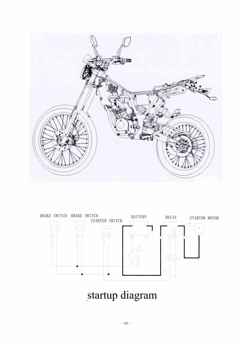
- 68 -
启动示意图
BATTERY RELAYBRAKE SWITCHBRAKE SWITCHSTARTER SWITCH
STARTOR MOTOR
startup diagram
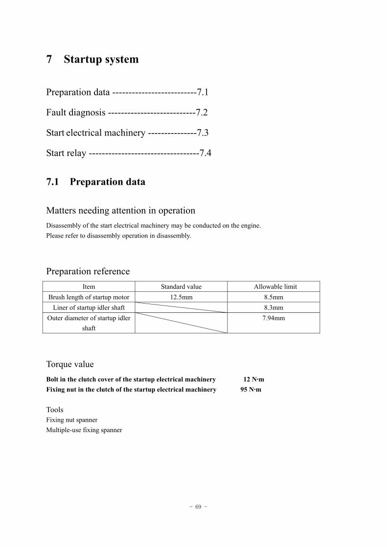
- 69 -
7 Startup system
Preparation data --------------------------7.1
Fault diagnosis ---------------------------7.2
Start electrical machinery ---------------7.3
Start relay ----------------------------------7.4
7.1 Preparation data
Matters needing attention in operation Disassembly of the start electrical machinery may be conducted on the engine. Please refer to disassembly operation in disassembly.
Preparation reference Item Standard value Allowable limit
Brush length of startup motor 12.5mm 8.5mm Liner of startup idler shaft 8.3mm
Outer diameter of startup idler shaft
7.94mm
Torque value Bolt in the clutch cover of the startup electrical machinery 12 N·m Fixing nut in the clutch of the startup electrical machinery 95 N·m Tools Fixing nut spanner Multiple-use fixing spanner
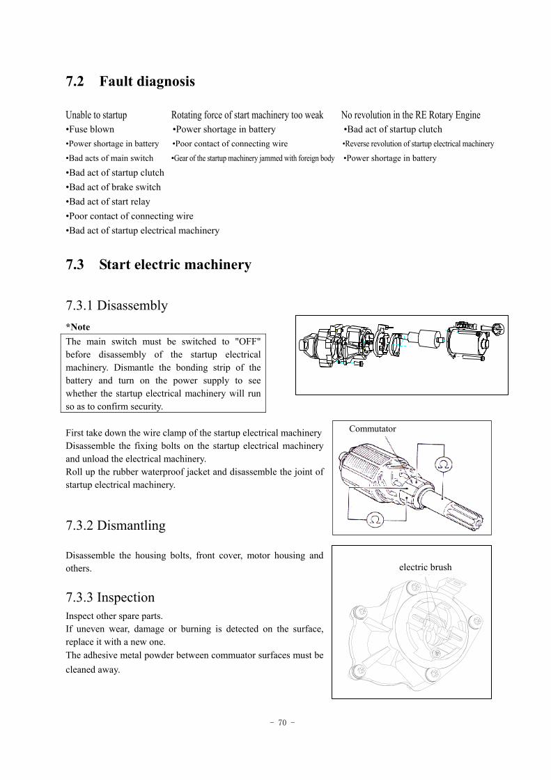
- 70 -
7.2 Fault diagnosis
Unable to startup Rotating force of start machinery too weak No revolution in the RE Rotary Engine •Fuse blown •Power shortage in battery •Bad act of startup clutch •Power shortage in battery •Poor contact of connecting wire •Reverse revolution of startup electrical machinery
•Bad acts of main switch •Gear of the startup machinery jammed with foreign body •Power shortage in battery
•Bad act of startup clutch •Bad act of brake switch •Bad act of start relay •Poor contact of connecting wire •Bad act of startup electrical machinery
7.3 Start electric machinery
7.3.1 Disassembly *Note The main switch must be switched to "OFF" before disassembly of the startup electrical machinery. Dismantle the bonding strip of the battery and turn on the power supply to see whether the startup electrical machinery will run so as to confirm security. First take down the wire clamp of the startup electrical machinery Disassemble the fixing bolts on the startup electrical machinery and unload the electrical machinery. Roll up the rubber waterproof jacket and disassemble the joint of startup electrical machinery.
7.3.2 Dismantling Disassemble the housing bolts, front cover, motor housing and others.
7.3.3 Inspection
Inspect other spare parts. If uneven wear, damage or burning is detected on the surface, replace it with a new one. The adhesive metal powder between commuator surfaces must be cleaned away.
电刷electric brush
Commutator
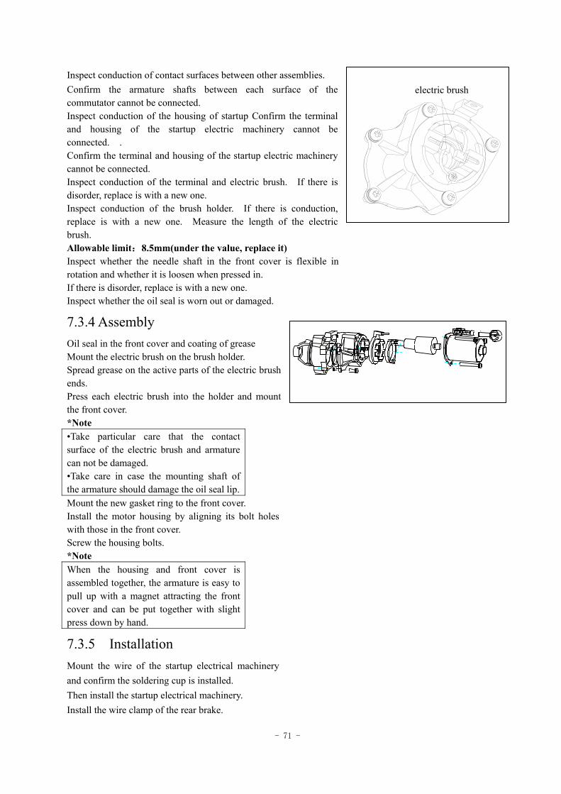
- 71 -
Inspect conduction of contact surfaces between other assemblies. Confirm the armature shafts between each surface of the commutator cannot be connected. Inspect conduction of the housing of startup Confirm the terminal and housing of the startup electric machinery cannot be connected. . Confirm the terminal and housing of the startup electric machinery cannot be connected. Inspect conduction of the terminal and electric brush. If there is disorder, replace is with a new one. Inspect conduction of the brush holder. If there is conduction, replace is with a new one. Measure the length of the electric brush. Allowable limit:8.5mm(under the value, replace it) Inspect whether the needle shaft in the front cover is flexible in rotation and whether it is loosen when pressed in. If there is disorder, replace is with a new one. Inspect whether the oil seal is worn out or damaged.
7.3.4 Assembly Oil seal in the front cover and coating of grease Mount the electric brush on the brush holder. Spread grease on the active parts of the electric brush ends. Press each electric brush into the holder and mount the front cover. *Note •Take particular care that the contact surface of the electric brush and armature can not be damaged. •Take care in case the mounting shaft of the armature should damage the oil seal lip. Mount the new gasket ring to the front cover. Install the motor housing by aligning its bolt holes with those in the front cover. Screw the housing bolts. *Note When the housing and front cover is assembled together, the armature is easy to pull up with a magnet attracting the front cover and can be put together with slight press down by hand.
7.3.5 Installation Mount the wire of the startup electrical machinery and confirm the soldering cup is installed. Then install the startup electrical machinery. Install the wire clamp of the rear brake.
电刷electric brush
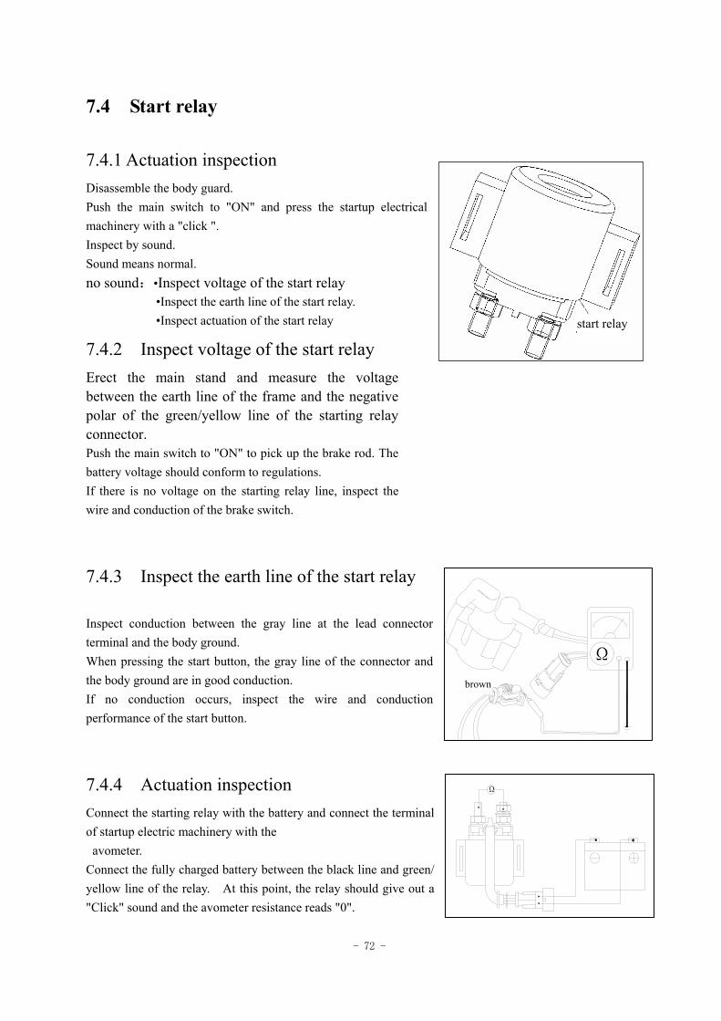
- 72 -
7.4 Start relay
7.4.1 Actuation inspection Disassemble the body guard. Push the main switch to "ON" and press the startup electrical machinery with a "click ". Inspect by sound. Sound means normal. no sound:•Inspect voltage of the start relay •Inspect the earth line of the start relay. •Inspect actuation of the start relay
7.4.2 Inspect voltage of the start relay Erect the main stand and measure the voltage between the earth line of the frame and the negative polar of the green/yellow line of the starting relay connector. Push the main switch to "ON" to pick up the brake rod. The battery voltage should conform to regulations. If there is no voltage on the starting relay line, inspect the wire and conduction of the brake switch.
7.4.3 Inspect the earth line of the start relay Inspect conduction between the gray line at the lead connector terminal and the body ground. When pressing the start button, the gray line of the connector and the body ground are in good conduction. If no conduction occurs, inspect the wire and conduction performance of the start button.
7.4.4 Actuation inspection Connect the starting relay with the battery and connect the terminal of startup electric machinery with the
avometer. Connect the fully charged battery between the black line and green/ yellow line of the relay. At this point, the relay should give out a "Click" sound and the avometer resistance reads "0".
Ω
Ω
灰
start relay
brown
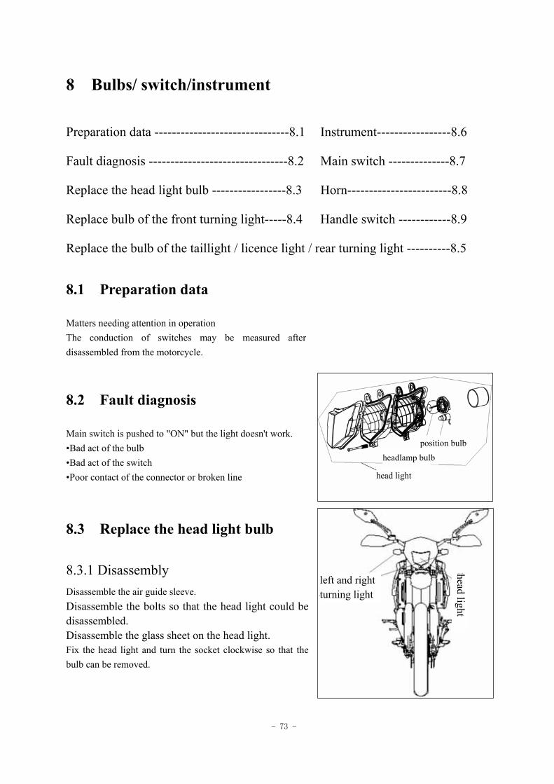
- 73 -
8 Bulbs/ switch/instrument
Preparation data -------------------------------8.1 Instrument-----------------8.6
Fault diagnosis --------------------------------8.2 Main switch --------------8.7
Replace the head light bulb -----------------8.3 Horn------------------------8.8
Replace bulb of the front turning light-----8.4 Handle switch ------------8.9
Replace the bulb of the taillight / licence light / rear turning light ----------8.5
8.1 Preparation data
Matters needing attention in operation The conduction of switches may be measured after disassembled from the motorcycle.
8.2 Fault diagnosis
Main switch is pushed to "ON" but the light doesn't work. •Bad act of the bulb •Bad act of the switch •Poor contact of the connector or broken line
8.3 Replace the head light bulb
8.3.1 Disassembly Disassemble the air guide sleeve. Disassemble the bolts so that the head light could be disassembled. Disassemble the glass sheet on the head light. Fix the head light and turn the socket clockwise so that the bulb can be removed.
position bulb
headlamp bulb
head light
left and right turning light
head light
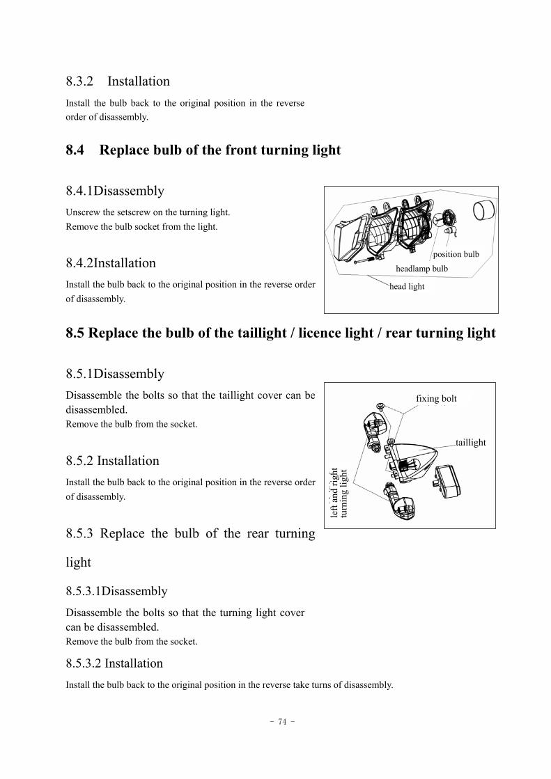
- 74 -
8.3.2 Installation
Install the bulb back to the original position in the reverse order of disassembly.
8.4 Replace bulb of the front turning light
8.4.1Disassembly Unscrew the setscrew on the turning light. Remove the bulb socket from the light.
8.4.2Installation Install the bulb back to the original position in the reverse order of disassembly.
8.5 Replace the bulb of the taillight / licence light / rear turning light
8.5.1Disassembly Disassemble the bolts so that the taillight cover can be disassembled. Remove the bulb from the socket. 8.5.2 Installation Install the bulb back to the original position in the reverse order of disassembly. 8.5.3 Replace the bulb of the rear turning
light
8.5.3.1Disassembly Disassemble the bolts so that the turning light cover can be disassembled. Remove the bulb from the socket.
8.5.3.2 Installation Install the bulb back to the original position in the reverse take turns of disassembly.
position bulb
headlamp bulb
head light
fixing bolt
taillight
left
and
right
tu
rnin
g lig
ht
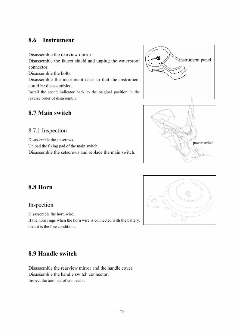
- 75 -
8.6 Instrument
Disassemble the rearview mirror; Disassemble the faucet shield and unplug the waterproof connector. Disassemble the bolts. Disassemble the instrument case so that the instrument could be disassembled. Install the speed indicator back to the original position in the reverse order of disassembly.
8.7 Main switch
8.7.1 Inspection Disassemble the setscrews. Unload the fixing pad of the main switch. Disassemble the setscrews and replace the main switch.
8.8 Horn
Inspection Disassemble the horn wire. If the horn rings when the horn wire is connected with the battery, then it is the fine conditions.
8.9 Handle switch
Disassemble the rearview mirror and the handle cover. Disassemble the handle switch connector. Inspect the terminal of connector.
电源开关
instrument panel
power switch
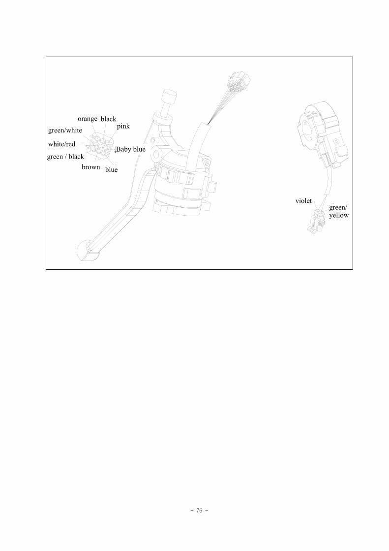
- 76 -
绿/白
白\红
绿/黑棕 蓝
黑橙
淡蓝
粉红
绿/黄
紫
white/red
green/white orange black
pink
Baby blue
bluebrown green / black
violet green/ yellow
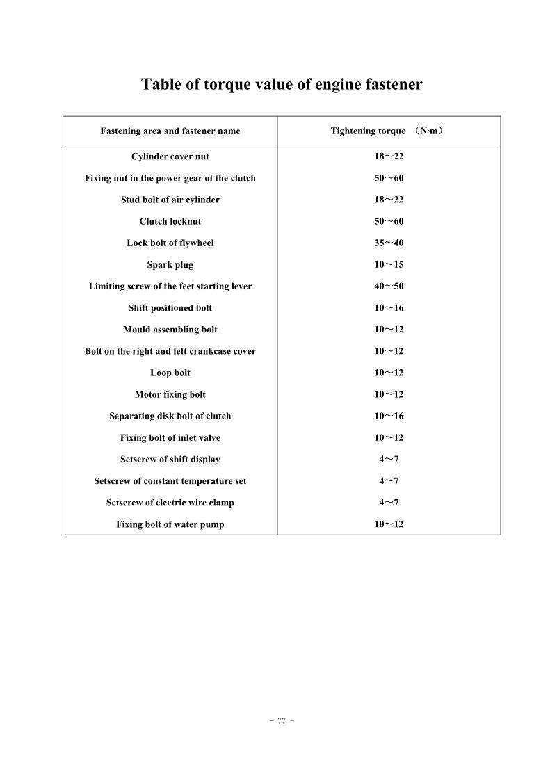
- 77 -
Table of torque value of engine fastener
Fastening area and fastener name Tightening torque (N·m)
Cylinder cover nut
Fixing nut in the power gear of the clutch
Stud bolt of air cylinder
Clutch locknut
Lock bolt of flywheel
Spark plug
Limiting screw of the feet starting lever
Shift positioned bolt
Mould assembling bolt
Bolt on the right and left crankcase cover
Loop bolt
Motor fixing bolt
Separating disk bolt of clutch
Fixing bolt of inlet valve
Setscrew of shift display
Setscrew of constant temperature set
Setscrew of electric wire clamp
Fixing bolt of water pump
18~22
50~60
18~22
50~60
35~40
10~15
40~50
10~16
10~12
10~12
10~12
10~12
10~16
10~12
4~7
4~7
4~7
10~12
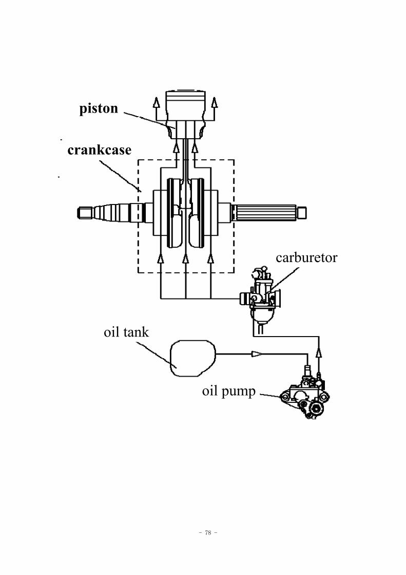
- 78 -
piston
crankcase
carburetor
oil tank
oil pump
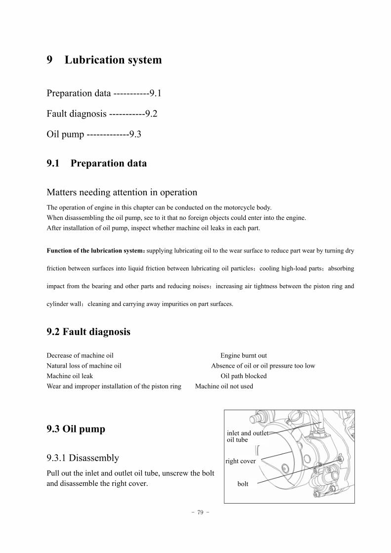
- 79 -
9 Lubrication system
Preparation data -----------9.1
Fault diagnosis -----------9.2
Oil pump -------------9.3
9.1 Preparation data
Matters needing attention in operation The operation of engine in this chapter can be conducted on the motorcycle body. When disassembling the oil pump, see to it that no foreign objects could enter into the engine. After installation of oil pump, inspect whether machine oil leaks in each part.
Function of the lubrication system:supplying lubricating oil to the wear surface to reduce part wear by turning dry
friction between surfaces into liquid friction between lubricating oil particles;cooling high-load parts;absorbing
impact from the bearing and other parts and reducing noises;increasing air tightness between the piston ring and
cylinder wall;cleaning and carrying away impurities on part surfaces.
9.2 Fault diagnosis
Decrease of machine oil Engine burnt out Natural loss of machine oil Absence of oil or oil pressure too low Machine oil leak Oil path blocked Wear and improper installation of the piston ring Machine oil not used
9.3 Oil pump
9.3.1 Disassembly Pull out the inlet and outlet oil tube, unscrew the bolt and disassemble the right cover.
inlet and outlet oil tube
right cover
bolt
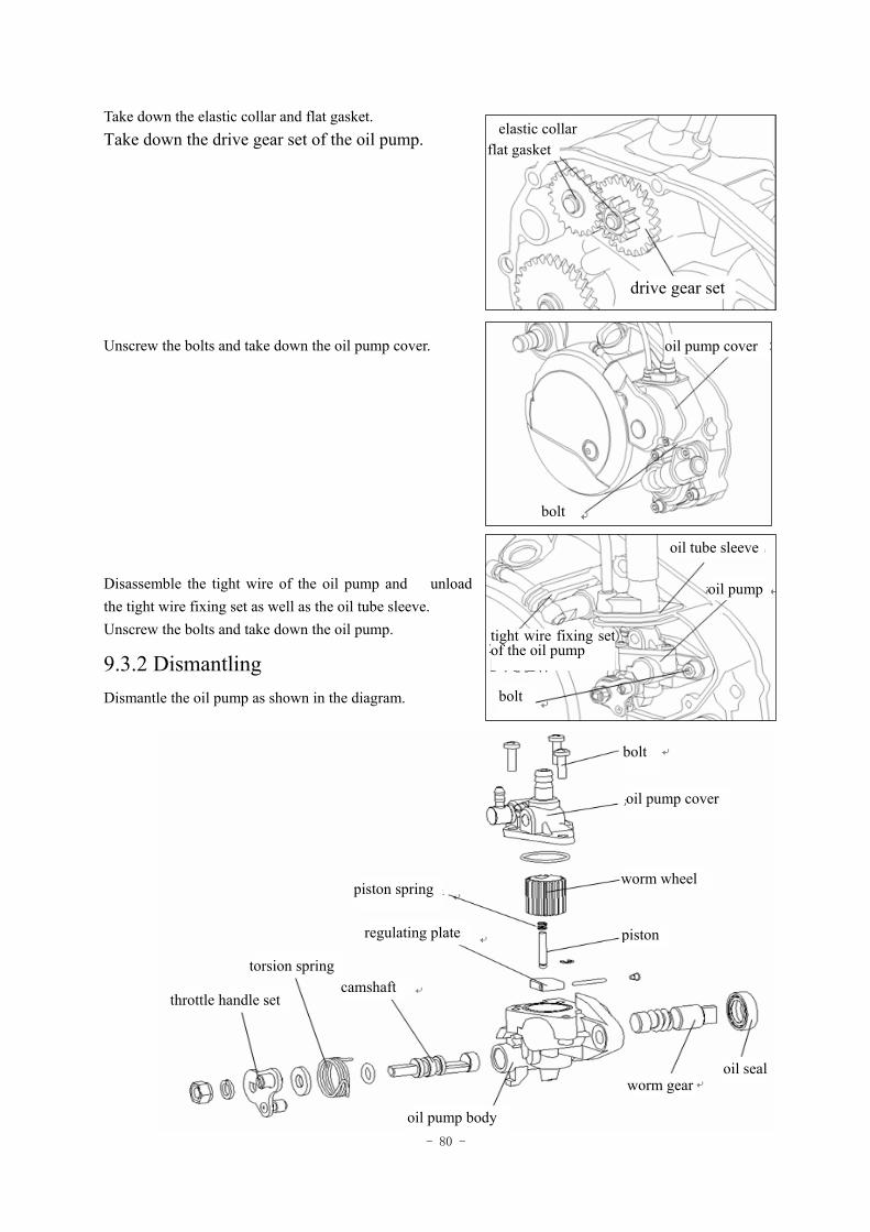
- 80 -
Take down the elastic collar and flat gasket. Take down the drive gear set of the oil pump. Unscrew the bolts and take down the oil pump cover.
Disassemble the tight wire of the oil pump and unload the tight wire fixing set as well as the oil tube sleeve. Unscrew the bolts and take down the oil pump.
9.3.2 Dismantling
Dismantle the oil pump as shown in the diagram.
elastic collarflat gasket
drive gear set
oil pump cover
bolt
oil tube sleeve
oil pump
tight wire fixing set of the oil pump
bolt
bolt
oil pump cover
piston spring worm wheel
regulating plate piston
torsion spring camshaft
throttle handle set
oil pump body
worm gear oil seal
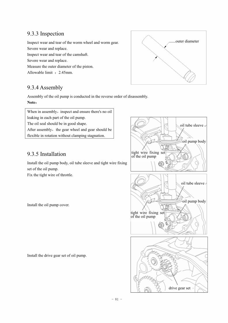
- 81 -
9.3.3 Inspection Inspect wear and tear of the worm wheel and worm gear. Severe wear and replace. Inspect wear and tear of the camshaft. Severe wear and replace. Measure the outer diameter of the piston. Allowable limit :2.45mm.
9.3.4 Assembly Assembly of the oil pump is conducted in the reverse order of disassembly. Note:
9.3.5 Installation Install the oil pump body, oil tube sleeve and tight wire fixing set of the oil pump. Fix the tight wire of throttle. Install the oil pump cover.
Install the drive gear set of oil pump.
When in assembly,inspect and ensure there's no oil leaking in each part of the oil pump. The oil seal should be in good shape. After assembly,the gear wheel and gear should be flexible in rotation without clamping stagnation.
外径outer diameter
oil tube sleeve
oil pump body
tight wire fixing set of the oil pump
tight wire fixing set of the oil pump
oil tube sleeve
oil pump body
drive gear set
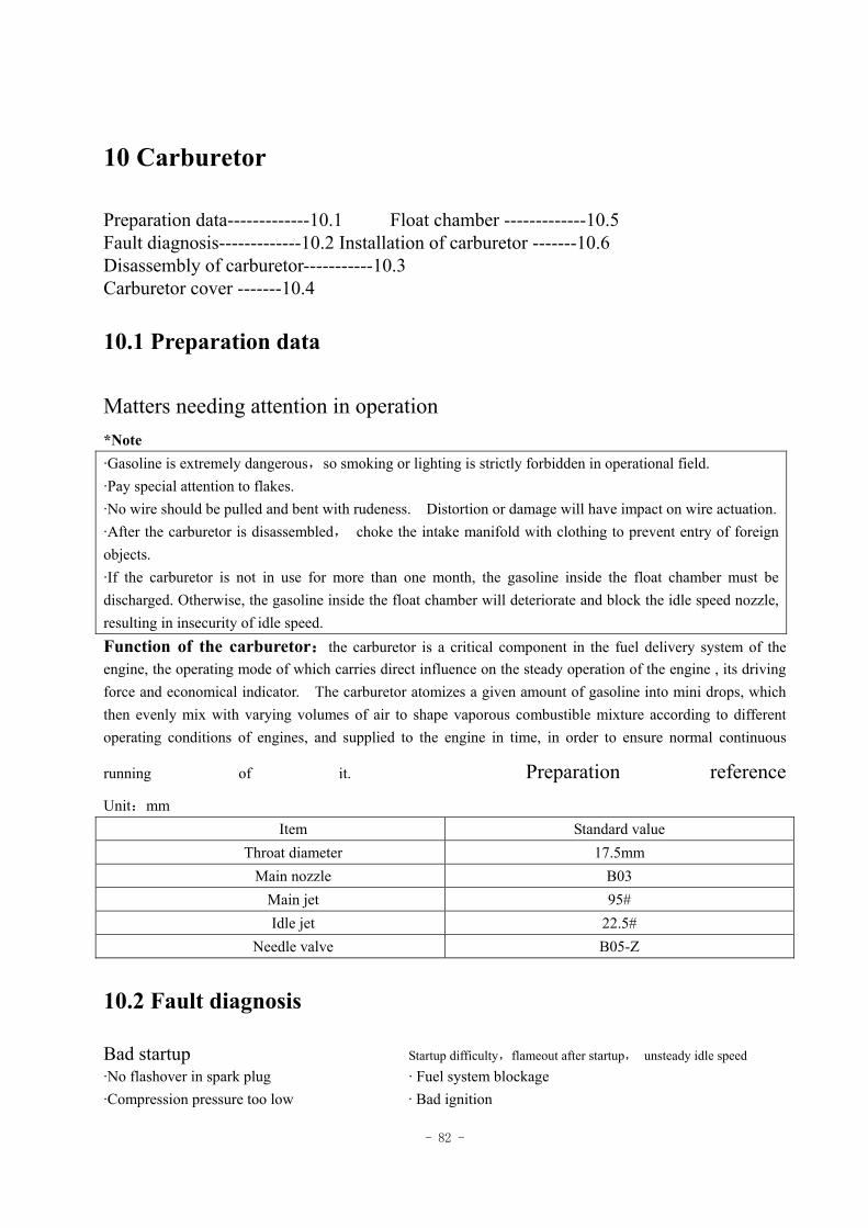
- 82 -
10 Carburetor
Preparation data-------------10.1 Float chamber -------------10.5 Fault diagnosis-------------10.2 Installation of carburetor -------10.6 Disassembly of carburetor-----------10.3 Carburetor cover -------10.4
10.1 Preparation data
Matters needing attention in operation *Note ·Gasoline is extremely dangerous,so smoking or lighting is strictly forbidden in operational field. ·Pay special attention to flakes. ·No wire should be pulled and bent with rudeness. Distortion or damage will have impact on wire actuation. ·After the carburetor is disassembled, choke the intake manifold with clothing to prevent entry of foreign objects. ·If the carburetor is not in use for more than one month, the gasoline inside the float chamber must be discharged. Otherwise, the gasoline inside the float chamber will deteriorate and block the idle speed nozzle, resulting in insecurity of idle speed. Function of the carburetor:the carburetor is a critical component in the fuel delivery system of the engine, the operating mode of which carries direct influence on the steady operation of the engine , its driving force and economical indicator. The carburetor atomizes a given amount of gasoline into mini drops, which then evenly mix with varying volumes of air to shape vaporous combustible mixture according to different operating conditions of engines, and supplied to the engine in time, in order to ensure normal continuous
running of it. Preparation reference
Unit:mm Item Standard value
Throat diameter 17.5mm Main nozzle B03
Main jet 95# Idle jet 22.5#
Needle valve B05-Z
10.2 Fault diagnosis
Bad startup Startup difficulty,flameout after startup, unsteady idle speed ·No flashover in spark plug · Fuel system blockage ·Compression pressure too low · Bad ignition
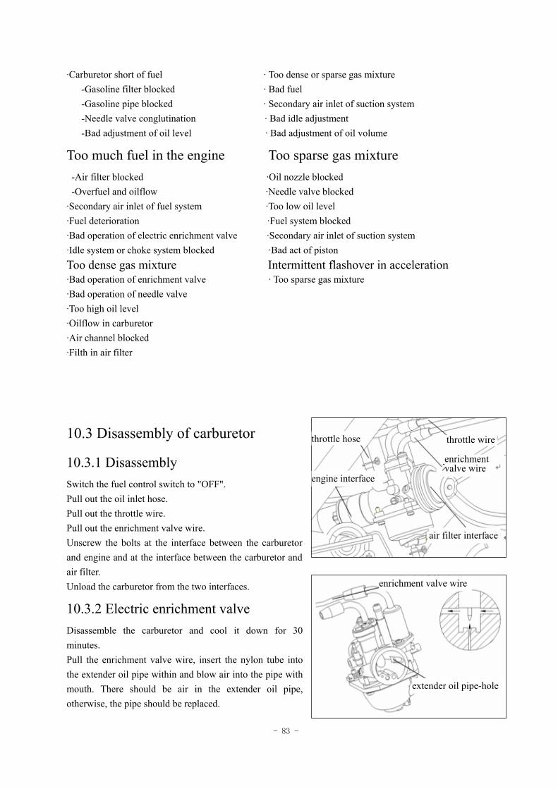
- 83 -
·Carburetor short of fuel · Too dense or sparse gas mixture -Gasoline filter blocked · Bad fuel -Gasoline pipe blocked · Secondary air inlet of suction system -Needle valve conglutination · Bad idle adjustment -Bad adjustment of oil level · Bad adjustment of oil volume
Too much fuel in the engine Too sparse gas mixture -Air filter blocked ·Oil nozzle blocked -Overfuel and oilflow ·Needle valve blocked ·Secondary air inlet of fuel system ·Too low oil level ·Fuel deterioration ·Fuel system blocked ·Bad operation of electric enrichment valve ·Secondary air inlet of suction system ·Idle system or choke system blocked ·Bad act of piston Too dense gas mixture Intermittent flashover in acceleration ·Bad operation of enrichment valve · Too sparse gas mixture ·Bad operation of needle valve ·Too high oil level ·Oilflow in carburetor ·Air channel blocked ·Filth in air filter
10.3 Disassembly of carburetor
10.3.1 Disassembly Switch the fuel control switch to "OFF". Pull out the oil inlet hose. Pull out the throttle wire. Pull out the enrichment valve wire. Unscrew the bolts at the interface between the carburetor and engine and at the interface between the carburetor and air filter. Unload the carburetor from the two interfaces.
10.3.2 Electric enrichment valve Disassemble the carburetor and cool it down for 30 minutes. Pull the enrichment valve wire, insert the nylon tube into the extender oil pipe within and blow air into the pipe with mouth. There should be air in the extender oil pipe, otherwise, the pipe should be replaced.
throttle hose throttle wire
enrichment valve wire
engine interface
air filter interface
enrichment valve wire
extender oil pipe-hole
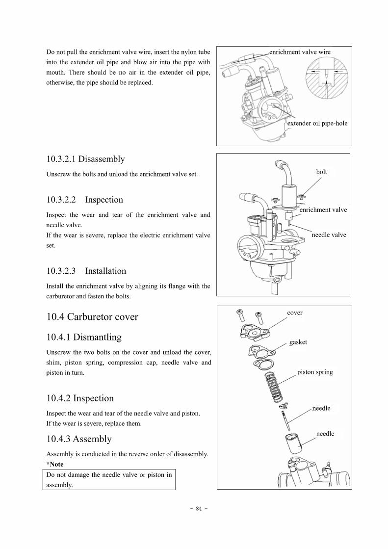
- 84 -
Do not pull the enrichment valve wire, insert the nylon tube into the extender oil pipe and blow air into the pipe with mouth. There should be no air in the extender oil pipe, otherwise, the pipe should be replaced.
10.3.2.1 Disassembly Unscrew the bolts and unload the enrichment valve set.
10.3.2.2 Inspection Inspect the wear and tear of the enrichment valve and needle valve. If the wear is severe, replace the electric enrichment valve set.
10.3.2.3 Installation Install the enrichment valve by aligning its flange with the carburetor and fasten the bolts.
10.4 Carburetor cover
10.4.1 Dismantling Unscrew the two bolts on the cover and unload the cover, shim, piston spring, compression cap, needle valve and piston in turn.
10.4.2 Inspection Inspect the wear and tear of the needle valve and piston. If the wear is severe, replace them.
10.4.3 Assembly Assembly is conducted in the reverse order of disassembly. *Note Do not damage the needle valve or piston in assembly.
cover
gasket
piston spring
needle
needle
needle valve
enrichment valve
bolt
extender oil pipe-hole
enrichment valve wire
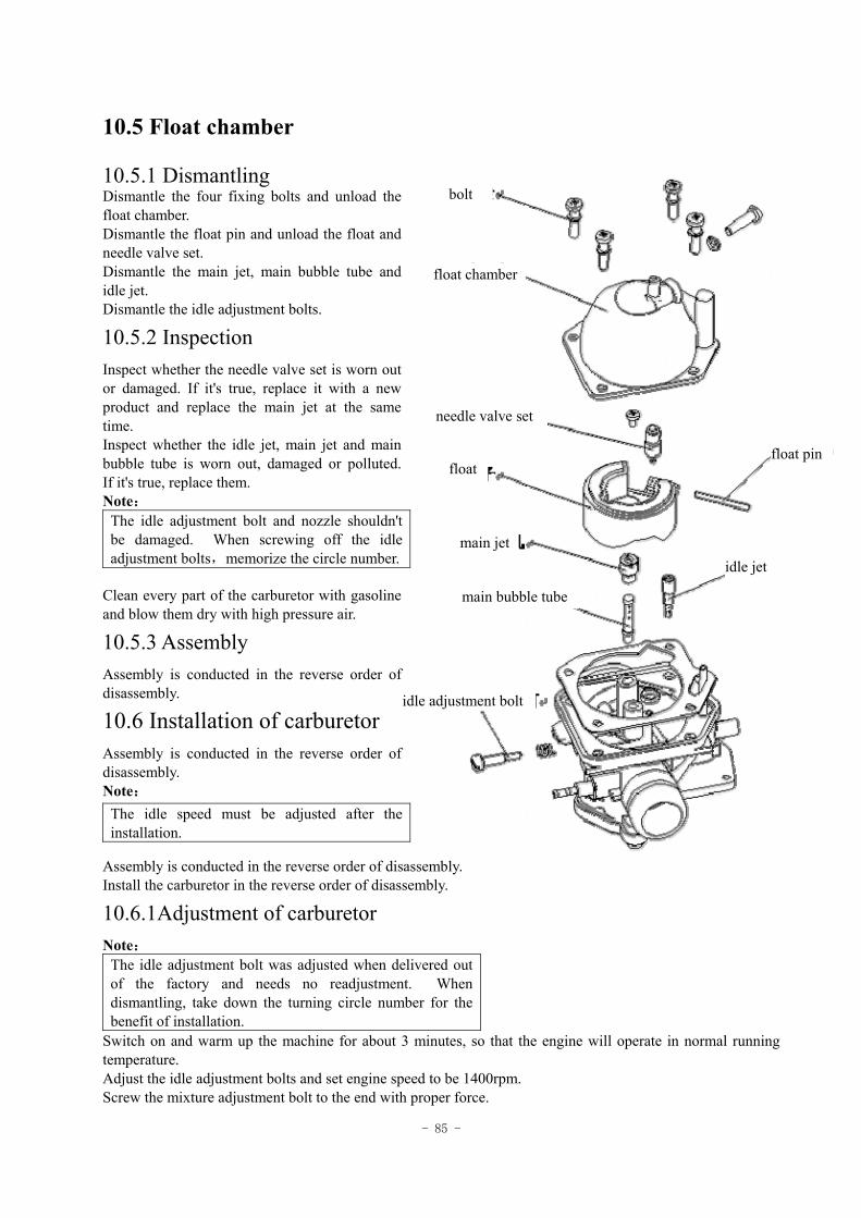
- 85 -
10.5 Float chamber
10.5.1 Dismantling Dismantle the four fixing bolts and unload the float chamber. Dismantle the float pin and unload the float and needle valve set. Dismantle the main jet, main bubble tube and idle jet. Dismantle the idle adjustment bolts.
10.5.2 Inspection Inspect whether the needle valve set is worn out or damaged. If it's true, replace it with a new product and replace the main jet at the same time. Inspect whether the idle jet, main jet and main bubble tube is worn out, damaged or polluted. If it's true, replace them. Note:
Clean every part of the carburetor with gasoline and blow them dry with high pressure air.
10.5.3 Assembly Assembly is conducted in the reverse order of disassembly.
10.6 Installation of carburetor Assembly is conducted in the reverse order of disassembly. Note:
Assembly is conducted in the reverse order of disassembly. Install the carburetor in the reverse order of disassembly.
10.6.1Adjustment of carburetor Note:
The idle adjustment bolt was adjusted when delivered out of the factory and needs no readjustment. When dismantling, take down the turning circle number for the benefit of installation.
Switch on and warm up the machine for about 3 minutes, so that the engine will operate in normal running temperature. Adjust the idle adjustment bolts and set engine speed to be 1400rpm. Screw the mixture adjustment bolt to the end with proper force.
The idle adjustment bolt and nozzle shouldn't be damaged. When screwing off the idle adjustment bolts,memorize the circle number.
The idle speed must be adjusted after the installation.
bolt
float chamber
needle valve set
float
main jet
float pin
main bubble tube
idle adjustment bolt
idle jet
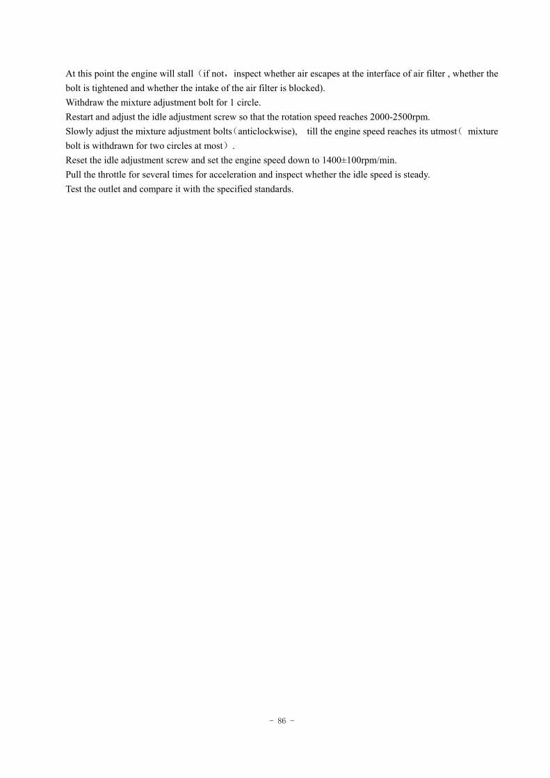
- 86 -
At this point the engine will stall(if not,inspect whether air escapes at the interface of air filter , whether the bolt is tightened and whether the intake of the air filter is blocked). Withdraw the mixture adjustment bolt for 1 circle. Restart and adjust the idle adjustment screw so that the rotation speed reaches 2000-2500rpm. Slowly adjust the mixture adjustment bolts(anticlockwise), till the engine speed reaches its utmost( mixture bolt is withdrawn for two circles at most). Reset the idle adjustment screw and set the engine speed down to 1400±100rpm/min. Pull the throttle for several times for acceleration and inspect whether the idle speed is steady. Test the outlet and compare it with the specified standards.
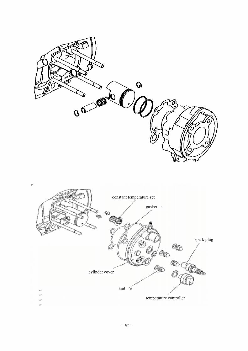
- 87 -
constant temperature set
gasket
spark plug
temperature controller
nut
cylinder cover
- 88 -
11 Cylinder cover/air cylinder/piston
Preparation data ---------------11.1
Fault diagnosis ---------------11.2
Disassembly of air cylinder -------------11.3
Disassembly and installation of the piston -------11.4
Installation of air cylinder -------------11.5
Disassembly of cylinder cover -----------11.6
Installation of cylinder cover - ---------11.7
11.1 Preparation data
Matters needing attention in operation ·The operation of air cylinder/piston can be conducted on the frame. ·Blow it dry with compressed air after dismantling, before inspection and test or after cleaning. ·In order to ensure the encapsulation of cylinder cover and cylinder body,the cylinder cover bears considerable bolt retightening force. Retightening force value:50Nm. All parts should be cleaned before inspection and test and should be blow dry with high pressure air. Function of the cylinder: the cylinder body provides space for the compression, burning and expansion of air and plays a steering function to piston motion. It also transmits part of the heat in the air cylinder to the surrounding cooling media. Function of piston: 1.Bearing the pressure caused by burning of combustible mixture gas and pass the pressure to the connecting rod, driving the rotation of the crankshaft. 2.Shaping a combustion chamber with the cylinder cover and others. 3.Acting as the sliding valve to lock and unlock the air channel, pressing the fresh air mixture in the crankcase into the air cylinder and ejecting the exhaust gas out of the air cylinder after combustion. Function of the cylinder cover :the cylinder cover is designed to encapsulate the air cylinder, constitute a combustion chamber with the piston and bear combustible gas with high pressure and high temperature.
Preparation reference Unit: mm
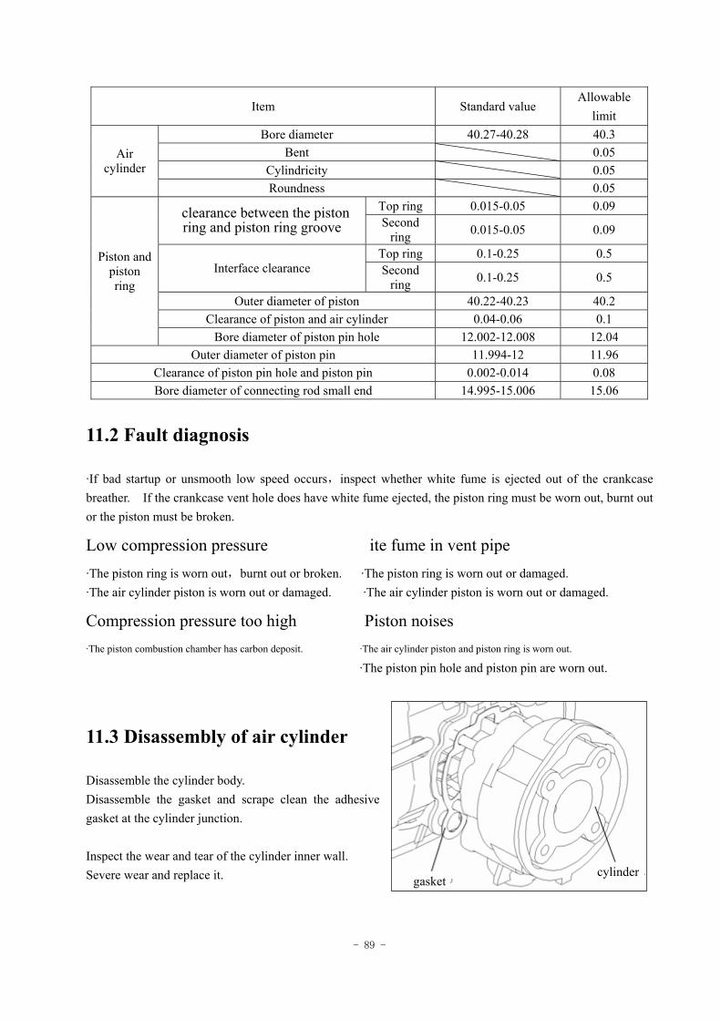
- 89 -
Item Standard value Allowable
limit Bore diameter 40.27-40.28 40.3
Bent 0.05 Cylindricity 0.05
Air cylinder
Roundness 0.05 Top ring 0.015-0.05 0.09 clearance between the piston
ring and piston ring groove Second ring 0.015-0.05 0.09
Top ring 0.1-0.25 0.5 Interface clearance Second
ring 0.1-0.25 0.5
Outer diameter of piston 40.22-40.23 40.2 Clearance of piston and air cylinder 0.04-0.06 0.1
Piston and piston ring
Bore diameter of piston pin hole 12.002-12.008 12.04 Outer diameter of piston pin 11.994-12 11.96
Clearance of piston pin hole and piston pin 0.002-0.014 0.08 Bore diameter of connecting rod small end 14.995-15.006 15.06
11.2 Fault diagnosis
·If bad startup or unsmooth low speed occurs,inspect whether white fume is ejected out of the crankcase breather. If the crankcase vent hole does have white fume ejected, the piston ring must be worn out, burnt out or the piston must be broken.
Low compression pressure ite fume in vent pipe
·The piston ring is worn out,burnt out or broken. ·The piston ring is worn out or damaged. ·The air cylinder piston is worn out or damaged. ·The air cylinder piston is worn out or damaged.
Compression pressure too high Piston noises ·The piston combustion chamber has carbon deposit. ·The air cylinder piston and piston ring is worn out.
·The piston pin hole and piston pin are worn out.
11.3 Disassembly of air cylinder
Disassemble the cylinder body. Disassemble the gasket and scrape clean the adhesive gasket at the cylinder junction. Inspect the wear and tear of the cylinder inner wall. Severe wear and replace it. gasket
cylinder
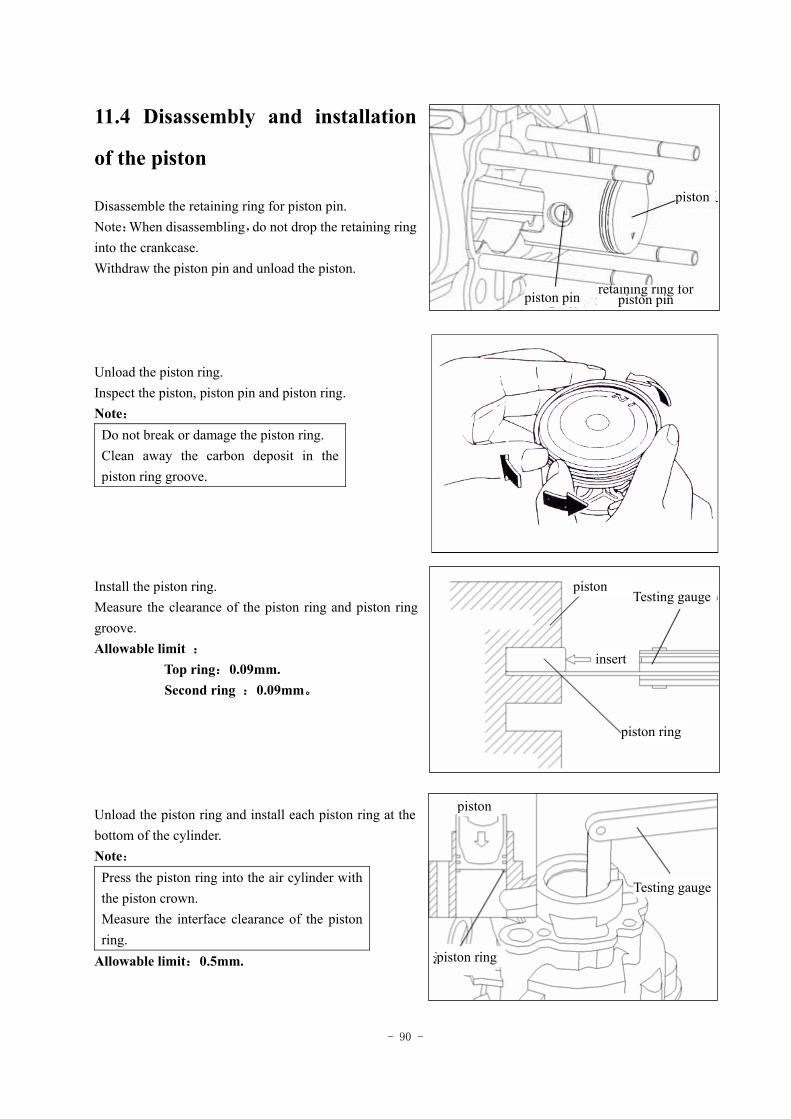
- 90 -
11.4 Disassembly and installation
of the piston
Disassemble the retaining ring for piston pin. Note:When disassembling,do not drop the retaining ring into the crankcase. Withdraw the piston pin and unload the piston. Unload the piston ring. Inspect the piston, piston pin and piston ring. Note:
Do not break or damage the piston ring. Clean away the carbon deposit in the piston ring groove.
Install the piston ring. Measure the clearance of the piston ring and piston ring groove. Allowable limit :
Top ring:0.09mm. Second ring :0.09mm。 Unload the piston ring and install each piston ring at the bottom of the cylinder. Note:
Press the piston ring into the air cylinder with the piston crown. Measure the interface clearance of the piston ring.
Allowable limit:0.5mm.
piston pin
piston
retaining ring for piston pin
piston Testing gauge
piston ring
insert
piston
piston ring
Testing gauge
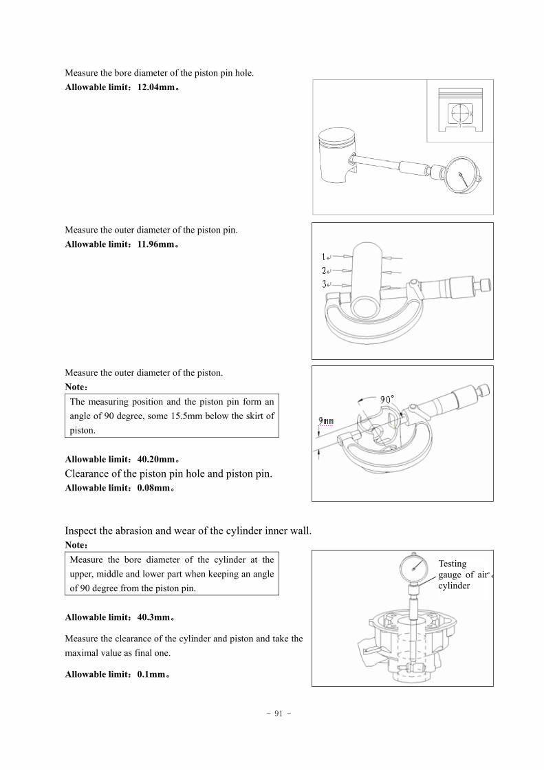
- 91 -
Measure the bore diameter of the piston pin hole. Allowable limit:12.04mm。 Measure the outer diameter of the piston pin. Allowable limit:11.96mm。 Measure the outer diameter of the piston. Note:
The measuring position and the piston pin form an angle of 90 degree, some 15.5mm below the skirt of piston.
Allowable limit:40.20mm。 Clearance of the piston pin hole and piston pin. Allowable limit:0.08mm。 Inspect the abrasion and wear of the cylinder inner wall. Note:
Measure the bore diameter of the cylinder at the upper, middle and lower part when keeping an angle of 90 degree from the piston pin.
Allowable limit:40.3mm。
Measure the clearance of the cylinder and piston and take the maximal value as final one.
Allowable limit:0.1mm。
Testing gauge of air cylinder
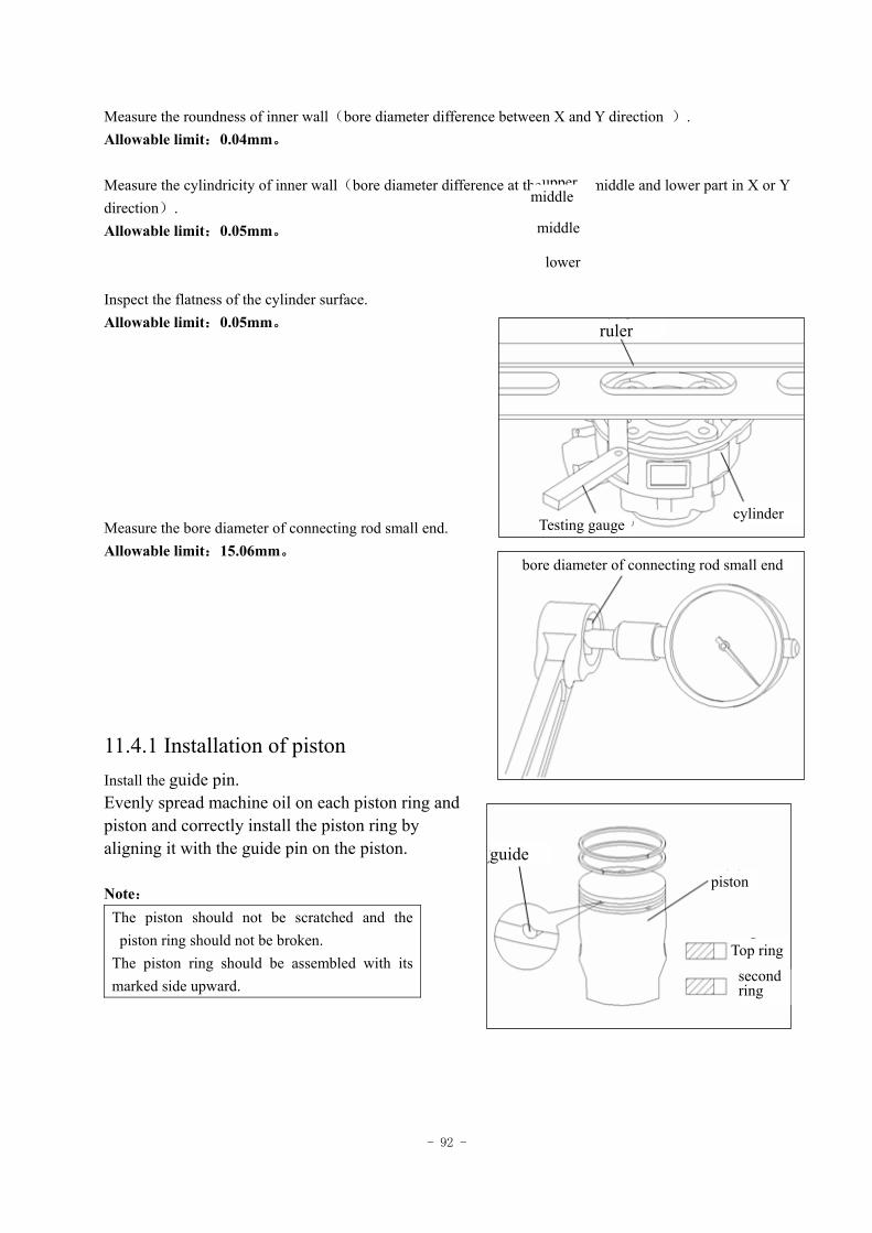
- 92 -
Measure the roundness of inner wall(bore diameter difference between X and Y direction ). Allowable limit:0.04mm。 Measure the cylindricity of inner wall(bore diameter difference at the upper , middle and lower part in X or Y direction). Allowable limit:0.05mm。 Inspect the flatness of the cylinder surface. Allowable limit:0.05mm。 Measure the bore diameter of connecting rod small end. Allowable limit:15.06mm。
11.4.1 Installation of piston Install the guide pin. Evenly spread machine oil on each piston ring and piston and correctly install the piston ring by aligning it with the guide pin on the piston. Note:
The piston should not be scratched and the piston ring should not be broken.
The piston ring should be assembled with its marked side upward.
upper middle
lower
middle
ruler
Testing gauge cylinder
bore diameter of connecting rod small end
guide piston
Top ring
second ring
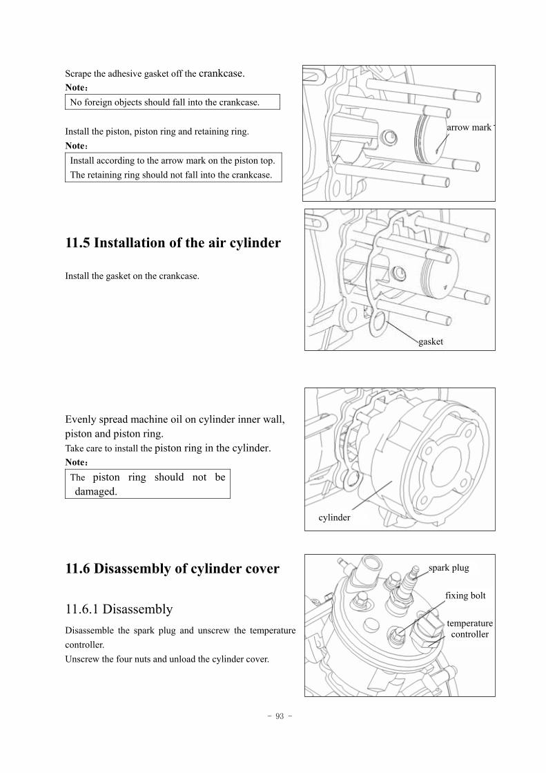
- 93 -
Scrape the adhesive gasket off the crankcase. Note:
No foreign objects should fall into the crankcase. Install the piston, piston ring and retaining ring. Note:
Install according to the arrow mark on the piston top. The retaining ring should not fall into the crankcase.
11.5 Installation of the air cylinder
Install the gasket on the crankcase. Evenly spread machine oil on cylinder inner wall, piston and piston ring. Take care to install the piston ring in the cylinder. Note:
The piston ring should not be damaged.
11.6 Disassembly of cylinder cover
11.6.1 Disassembly Disassemble the spark plug and unscrew the temperature controller. Unscrew the four nuts and unload the cylinder cover.
arrow mark
gasket
cylinder
spark plug
temperature controller
fixing bolt
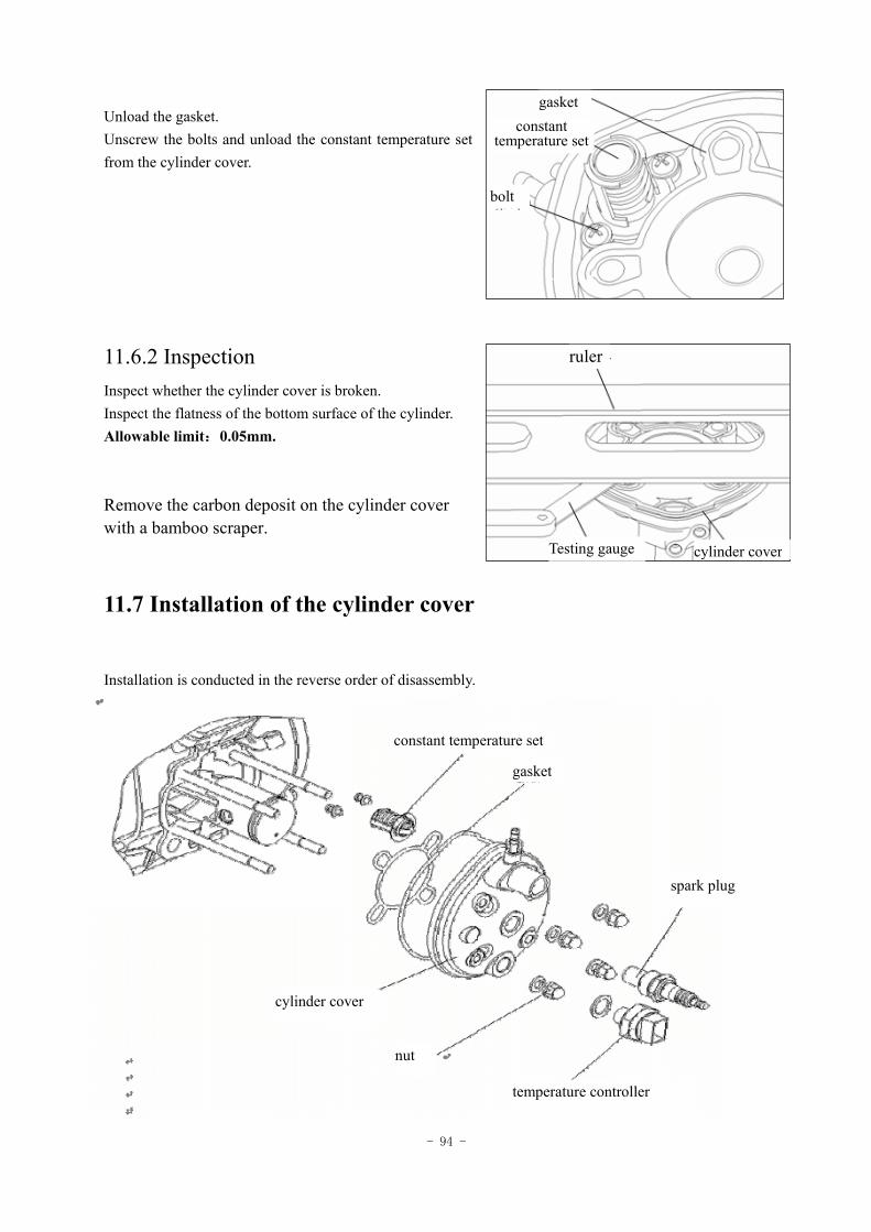
- 94 -
Unload the gasket. Unscrew the bolts and unload the constant temperature set from the cylinder cover.
11.6.2 Inspection Inspect whether the cylinder cover is broken. Inspect the flatness of the bottom surface of the cylinder. Allowable limit:0.05mm. Remove the carbon deposit on the cylinder cover with a bamboo scraper.
11.7 Installation of the cylinder cover
Installation is conducted in the reverse order of disassembly.
constant temperature set
gasket
spark plug
temperature controller
nut
cylinder cover
gasket constant
temperature set
bolt
ruler
Testing gauge cylinder cover
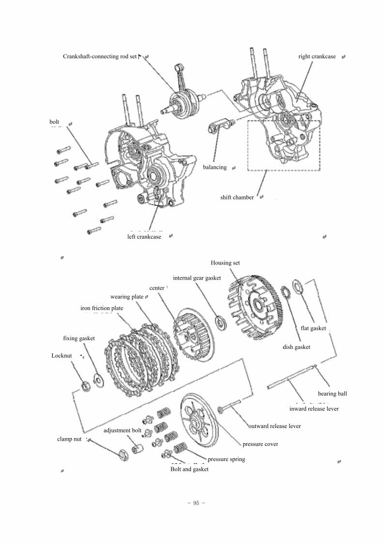
- 95 -
Crankshaft-connecting rod set right crankcase
bolt
balancing
shift chamber
left crankcase
Housing set
internal gear gasket
centerwearing plate
iron friction plate
fixing gasket
Locknut
clamp nut
flat gasket
dish gasket
bearing ball
inward release lever
outward release lever
pressure cover
pressure spring
Bolt and gasket
adjustment bolt
- 96 -
12 Crankcase/clutch/actuating lever
Preparation data ----------------12.1
Fault diagnosis -----------------12.2
Crankcase -----------------------12.3
Clutch ---------------------------12.4
Actuating lever -----------------12.5
12.1 Preparation data
Matters needing attention in operation Since the crankcase is a thin-section casting, please avoid impact on it during operation in case there is any distortion or rupture. All parts should be cleaned before inspection and test and should be blow dry with high pressure air. Before operation, discharge the lubricating oil in the crankcase. Function of the crankcase:the bearing part of the engine. Its primary function is supporting the crankshaft, clutch, gearbox, cylinder body as well as the cylinder cover and bearing bursting impact of combustion and movement inertia force of crankshaft connecting rod system and constituting some closed (oil, air seal) space. The crankcase has a hanging hole which links the engine and the frame with other parts by connecting with the hanging hole.
Preparation reference Unit:mm
Item Standard value Allowable limit clearance of connecting
rod big end in right and left direction
0.1-0.35 0.55
axial clearance of connecting rod big end in
vertical angle
0-0.008 0.05 Crankshaft
vibration 0.1 Thickness of wearing plate 2.9-3 2.6
Clutch Length of pressure spring 29.4-30.6 29.0 Bore diameter of shift fork 7.825-7.845 7.91
Thickness of shift fork 3.95-4.05 3.9 Outer diameter of shift drum 41.8-42 41.75
Shift mechanism
Locked groove width of shift drum
6.05-6.15 6.3
Tools Multiple use fixer Clutch spring compressors Driver's perch Box spanner Guide rod Bearing driver
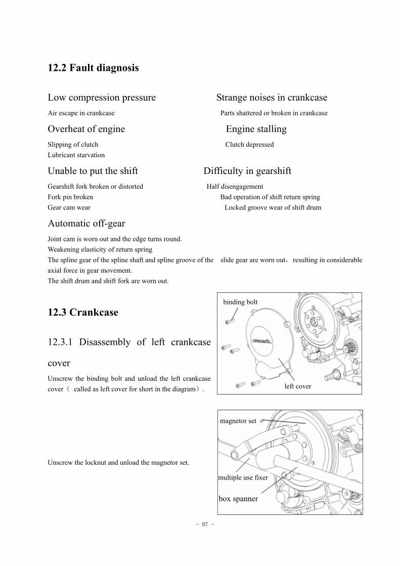
- 97 -
12.2 Fault diagnosis
Low compression pressure Strange noises in crankcase Air escape in crankcase Parts shattered or broken in crankcase
Overheat of engine Engine stalling Slipping of clutch Clutch depressed Lubricant starvation
Unable to put the shift Difficulty in gearshift Gearshift fork broken or distorted Half disengagement Fork pin broken Bad operation of shift return spring Gear cam wear Locked groove wear of shift drum
Automatic off-gear
Joint cam is worn out and the edge turns round. Weakening elasticity of return spring The spline gear of the spline shaft and spline groove of the slide gear are worn out, resulting in considerable axial force in gear movement. The shift drum and shift fork are worn out.
12.3 Crankcase
12.3.1 Disassembly of left crankcase
cover Unscrew the binding bolt and unload the left crankcase cover( called as left cover for short in the diagram). Unscrew the locknut and unload the magnetor set.
binding bolt
magnetor set
multiple use fixer
box spanner
left cover
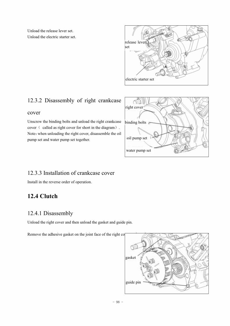
- 98 -
Unload the release lever set. Unload the electric starter set.
12.3.2 Disassembly of right crankcase
cover Unscrew the binding bolts and unload the right crankcase cover( called as right cover for short in the diagram). Note:when unloading the right cover, disassemble the oil pump set and water pump set together.
12.3.3 Installation of crankcase cover Install in the reverse order of operation.
12.4 Clutch
12.4.1 Disassembly Unload the right cover and then unload the gasket and guide pin. Remove the adhesive gasket on the joint face of the right cover and crankcase.
guide pin
gasket
water pump set
oil pump set
binding bolts
right cover
electric starter set
release lever set
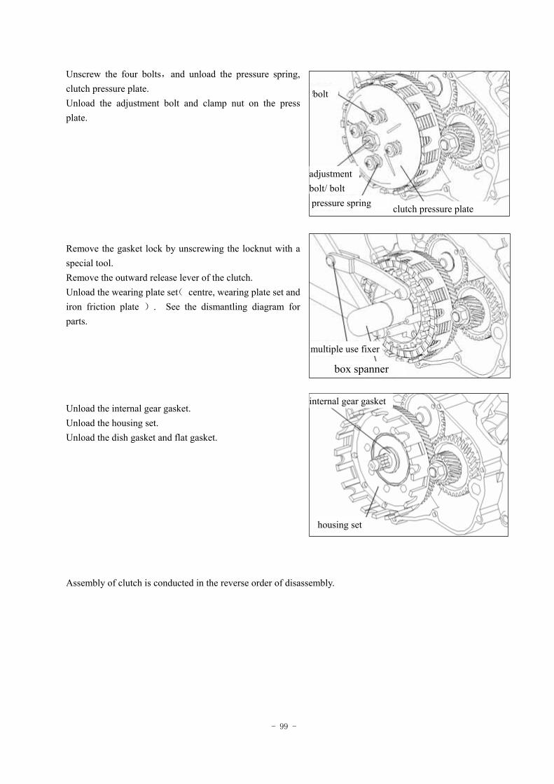
- 99 -
Unscrew the four bolts,and unload the pressure spring, clutch pressure plate. Unload the adjustment bolt and clamp nut on the press plate. Remove the gasket lock by unscrewing the locknut with a special tool. Remove the outward release lever of the clutch. Unload the wearing plate set( centre, wearing plate set and iron friction plate ). See the dismantling diagram for parts. Unload the internal gear gasket. Unload the housing set. Unload the dish gasket and flat gasket. Assembly of clutch is conducted in the reverse order of disassembly.
bolt
adjustment bolt/ bolt pressure spring clutch pressure plate
multiple use fixer
box spanner
internal gear gasket
housing set
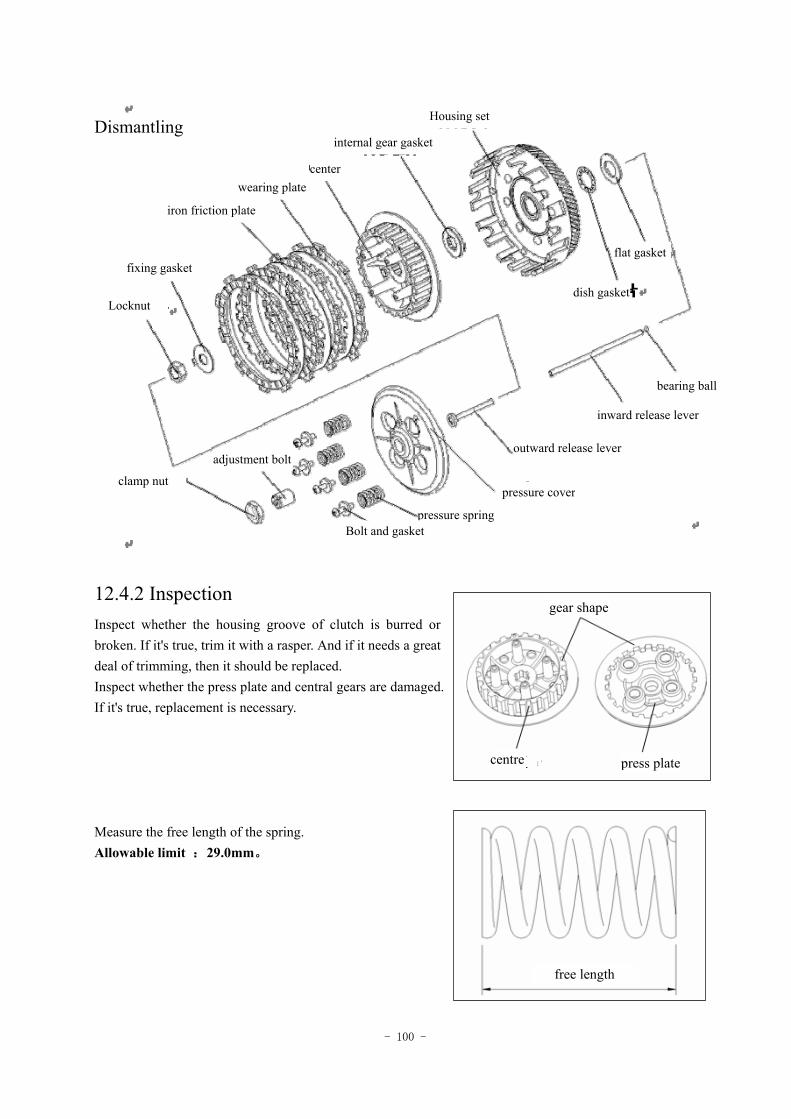
- 100 -
12.4.2 Inspection Inspect whether the housing groove of clutch is burred or broken. If it's true, trim it with a rasper. And if it needs a great deal of trimming, then it should be replaced. Inspect whether the press plate and central gears are damaged. If it's true, replacement is necessary. Measure the free length of the spring. Allowable limit :29.0mm。
Dismantling Housing set
internal gear gasket
center wearing plate
iron friction plate
fixing gasket
Locknut
flat gasket
dish gasket
bearing ball
inward release lever
outward release lever
pressure cover
pressure spring Bolt and gasket
clamp nut
adjustment bolt
gear shape
centre press plate
free length
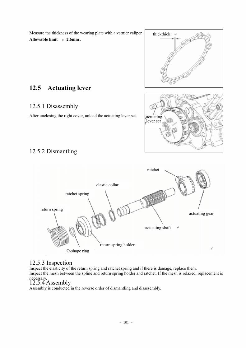
- 101 -
Measure the thickness of the wearing plate with a vernier caliper. Allowable limit :2.6mm。
12.5 Actuating lever
12.5.1 Disassembly After unclosing the right cover, unload the actuating lever set.
12.5.2 Dismantling
12.5.3 Inspection Inspect the elasticity of the return spring and ratchet spring and if there is damage, replace them. Inspect the mesh between the spline and return spring holder and ratchet. If the mesh is relaxed, replacement is necessary. 12.5.4 Assembly Assembly is conducted in the reverse order of dismantling and disassembly.
thickthick
actuating lever set
ratchet
elastic collar
ratchet spring
return spring
O-shape ring return spring holder
actuating shaft
actuating gear
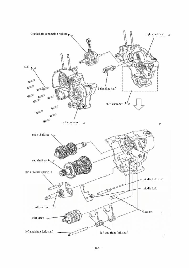
- 102 -
Crankshaft-connecting rod set right crankcase
bolt
balancing shaft
shift chamber
left crankcase
main shaft set
sub shaft set
pin of return spring
shift shaft set
middle fork shaft
middle fork
fixer set
shift drum
left and right fork shaft left and right fork shaft
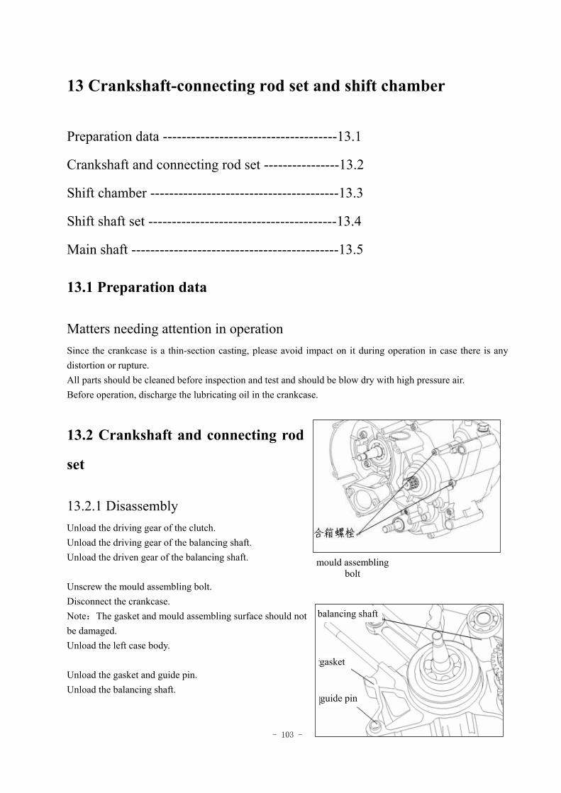
- 103 -
13 Crankshaft-connecting rod set and shift chamber
Preparation data -------------------------------------13.1
Crankshaft and connecting rod set ----------------13.2
Shift chamber ----------------------------------------13.3
Shift shaft set ----------------------------------------13.4
Main shaft --------------------------------------------13.5
13.1 Preparation data
Matters needing attention in operation Since the crankcase is a thin-section casting, please avoid impact on it during operation in case there is any distortion or rupture. All parts should be cleaned before inspection and test and should be blow dry with high pressure air. Before operation, discharge the lubricating oil in the crankcase.
13.2 Crankshaft and connecting rod
set
13.2.1 Disassembly Unload the driving gear of the clutch. Unload the driving gear of the balancing shaft. Unload the driven gear of the balancing shaft. Unscrew the mould assembling bolt. Disconnect the crankcase. Note:The gasket and mould assembling surface should not be damaged. Unload the left case body. Unload the gasket and guide pin. Unload the balancing shaft.
mould assembling bolt
balancing shaft
gasket
guide pin
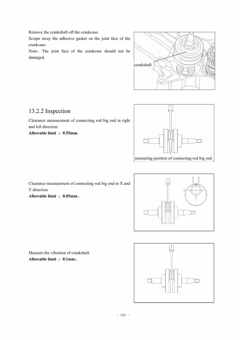
- 104 -
Remove the crankshaft off the crankcase. Scrape away the adhesive gasket on the joint face of the crankcase. Note:The joint face of the crankcase should not be damaged.
13.2.2 Inspection Clearance measurement of connecting rod big end in right and left direction Allowable limit :0.55mm. Clearance measurement of connecting rod big end in X and Y direction Allowable limit :0.05mm。 Measure the vibration of crankshaft. Allowable limit :0.1mm。
measuring position of connecting rod big end
crankshaft
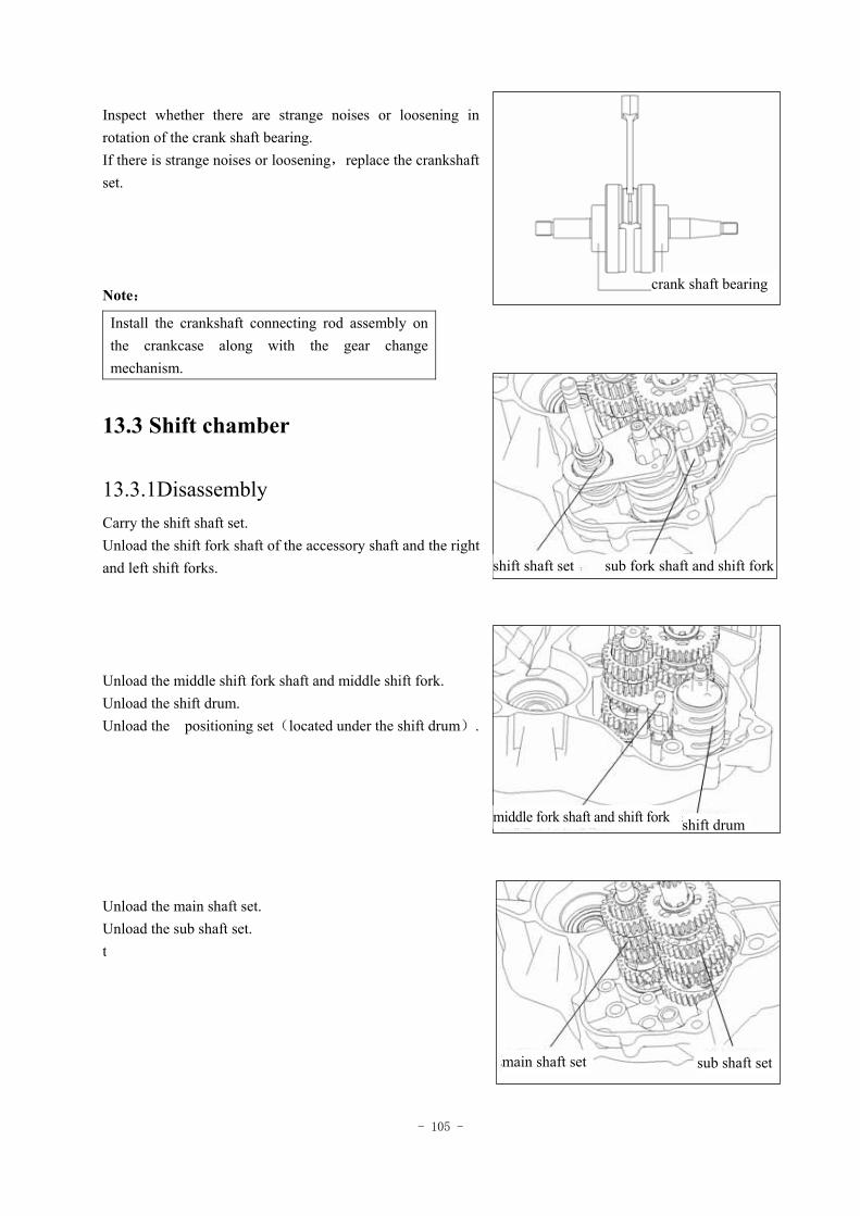
- 105 -
Inspect whether there are strange noises or loosening in rotation of the crank shaft bearing. If there is strange noises or loosening,replace the crankshaft set. Note:
13.3 Shift chamber
13.3.1Disassembly Carry the shift shaft set. Unload the shift fork shaft of the accessory shaft and the right and left shift forks. Unload the middle shift fork shaft and middle shift fork. Unload the shift drum. Unload the positioning set(located under the shift drum). Unload the main shaft set. Unload the sub shaft set. t
Install the crankshaft connecting rod assembly on the crankcase along with the gear change mechanism.
main shaft set sub shaft set
crank shaft bearing
shift shaft set sub fork shaft and shift fork
middle fork shaft and shift fork shift drum
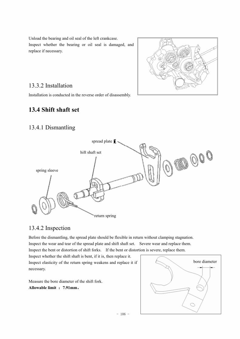
- 106 -
Unload the bearing and oil seal of the left crankcase. Inspect whether the bearing or oil seal is damaged, and replace if necessary.
13.3.2 Installation Installation is conducted in the reverse order of disassembly.
13.4 Shift shaft set
13.4.1 Dismantling
13.4.2 Inspection Before the dismantling, the spread plate should be flexible in return without clamping stagnation. Inspect the wear and tear of the spread plate and shift shaft set. Severe wear and replace them. Inspect the bent or distortion of shift forks. If the bent or distortion is severe, replace them. Inspect whether the shift shaft is bent, if it is, then replace it. Inspect elasticity of the return spring weakens and replace it if necessary. Measure the bore diameter of the shift fork. Allowable limit :7.91mm。
bore diameter
return spring
spring sleeve
hift shaft set
spread plate
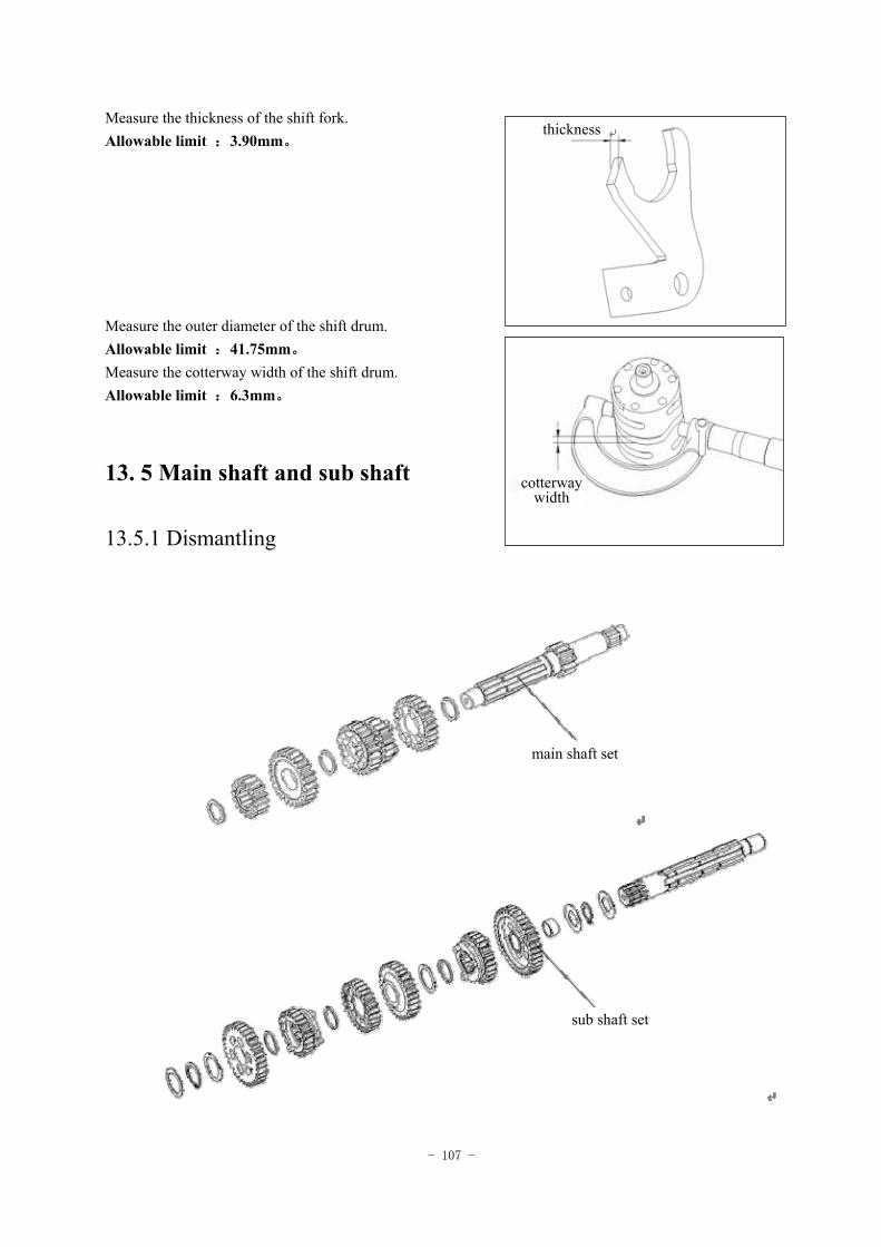
- 107 -
Measure the thickness of the shift fork. Allowable limit :3.90mm。 Measure the outer diameter of the shift drum. Allowable limit :41.75mm。 Measure the cotterway width of the shift drum. Allowable limit :6.3mm。
13. 5 Main shaft and sub shaft
13.5.1 Dismantling
sub shaft set
main shaft set
cotterway width
thickness
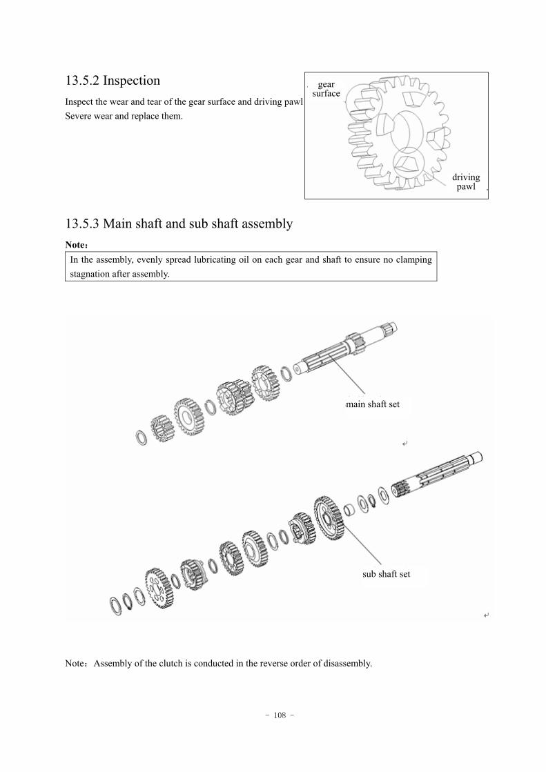
- 108 -
13.5.2 Inspection Inspect the wear and tear of the gear surface and driving pawl respectively. Severe wear and replace them.
13.5.3 Main shaft and sub shaft assembly Note:
In the assembly, evenly spread lubricating oil on each gear and shaft to ensure no clamping stagnation after assembly.
Note:Assembly of the clutch is conducted in the reverse order of disassembly.
gear surface
driving pawl
main shaft set
sub shaft set
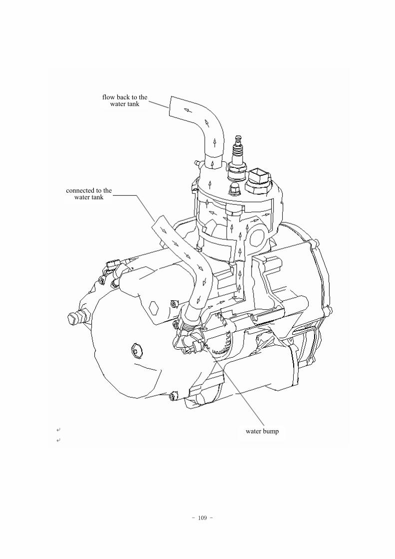
- 109 -
flow back to the water tank
connected to the water tank
water bump
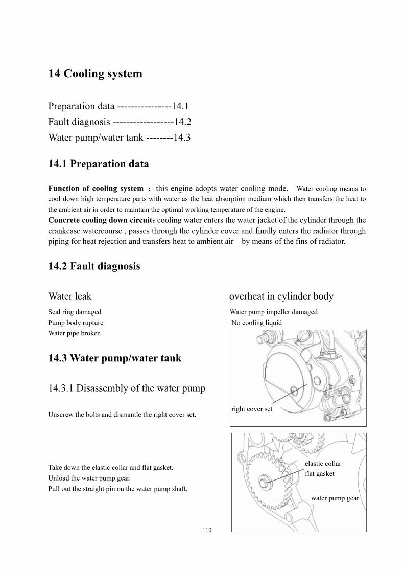
- 110 -
14 Cooling system
Preparation data ----------------14.1 Fault diagnosis ------------------14.2 Water pump/water tank --------14.3
14.1 Preparation data
Function of cooling system :this engine adopts water cooling mode. Water cooling means to cool down high temperature parts with water as the heat absorption medium which then transfers the heat to the ambient air in order to maintain the optimal working temperature of the engine. Concrete cooling down circuit:cooling water enters the water jacket of the cylinder through the crankcase watercourse , passes through the cylinder cover and finally enters the radiator through piping for heat rejection and transfers heat to ambient air by means of the fins of radiator.
14.2 Fault diagnosis
Water leak overheat in cylinder body Seal ring damaged Water pump impeller damaged Pump body rupture No cooling liquid Water pipe broken
14.3 Water pump/water tank
14.3.1 Disassembly of the water pump
Unscrew the bolts and dismantle the right cover set. Take down the elastic collar and flat gasket. Unload the water pump gear. Pull out the straight pin on the water pump shaft.
water pump gear
elastic collar flat gasket
right cover set
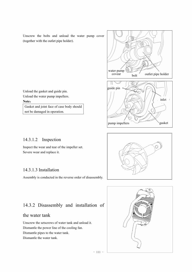
- 111 -
Unscrew the bolts and unload the water pump cover (together with the outlet pipe holder). Unload the gasket and guide pin. Unload the water pump impellers. Note:
Gasket and joint face of case body should not be damaged in operation.
14.3.1.2 Inspection Inspect the wear and tear of the impeller set. Severe wear and replace it.
14.3.1.3 Installation Assembly is conducted in the reverse order of disassembly.
14.3.2 Disassembly and installation of
the water tank Unscrew the setscrews of water tank and unload it. Dismantle the power line of the cooling fan. Dismantle pipes to the water tank. Dismantle the water tank.
water pump covear outlet pipe holder bolt
guide pin
inlet
gasket pump impellers
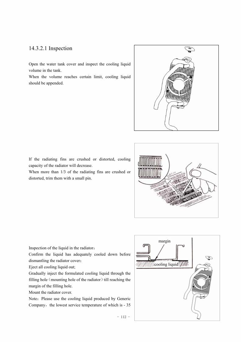
- 112 -
14.3.2.1 Inspection Open the water tank cover and inspect the cooling liquid volume in the tank. When the volume reaches certain limit, cooling liquid should be appended.
If the radiating fins are crushed or distorted, cooling capacity of the radiator will decrease. When more than 1/3 of the radiating fins are crushed or distorted, trim them with a small pin.
Inspection of the liquid in the radiator: Confirm the liquid has adequately cooled down before dismantling the radiator cover; Eject all cooling liquid out; Gradually inject the formulated cooling liquid through the filling hole(mounting hole of the radiator)till reaching the margin of the filling hole. Mount the radiator cover. Note:Please use the cooling liquid produced by Generic Company,the lowest service temperature of which is - 35
cooling liquid
margin
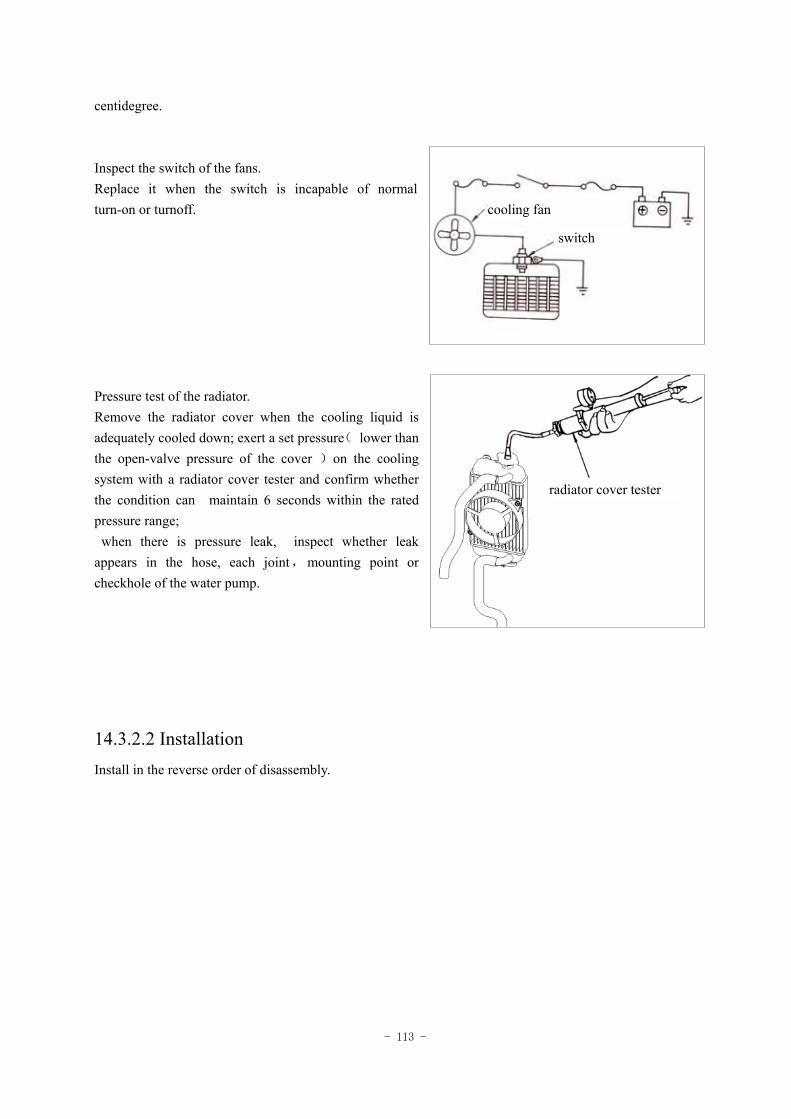
- 113 -
centidegree. Inspect the switch of the fans. Replace it when the switch is incapable of normal turn-on or turnoff.
Pressure test of the radiator. Remove the radiator cover when the cooling liquid is adequately cooled down; exert a set pressure( lower than the open-valve pressure of the cover )on the cooling system with a radiator cover tester and confirm whether the condition can maintain 6 seconds within the rated pressure range;
when there is pressure leak, inspect whether leak appears in the hose, each joint,mounting point or checkhole of the water pump.
14.3.2.2 Installation Install in the reverse order of disassembly.
cooling fan
switch
radiator cover tester
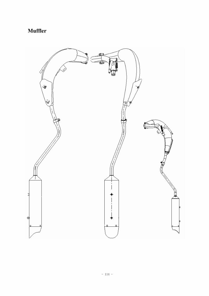
- 114 -
Muffler
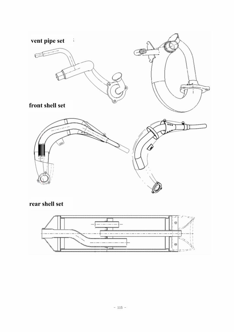
- 115 -
vent pipe set
front shell set
rear shell set
- 116 -
15 Exhaust emission and control system
Warranty of Exhaust emission and control system ----------------------------15.1 Regular maintenance guideline/ensurance of emission standard ------------15.2 Mechanical function of the exhaust control system ----------------------------15.3 Catalyst converter system ----------------------------------------------------------15.4 Countermeasures to idle speed emission exceeding specified value ---------15.5
15.1 Warranty of Exhaust emission and control system
1. The exhaust emission and control system of this motorcycle conforms to European Union EC/97/24/5/I and the revised version of 2003/77/EC B stage. Our Company gives warranty if the user fully follows regular service and specified maintenance of the system in effective service life. 2. Warranty scope 1〉Function warranty of exhaust emission and control system We guarantee that within riding of 15 thousand km, regular or irregular exhaust inspection standards implemented by the government will be satisfied. 3. If the following conditions occur, this warranty clause is not applicable, but maintenance and service at a reasonable price will be provided to customers by our dealers or service departments at province or city level. 1〉Regular maintenance is not performed in accordance with the specified time or service kilometers by our Company. 2〉Those who do not have regular inspection,adjustment or service at our dealers or service centers or who fail to bring forward the maintenance records. 3〉Overload or improper use 4〉Reconstruction of the vehicle, disassembly of original binding parts or mounting other equipment at will
5〉Used for racing or frequent riding on roads for non-motorized vehicles 6〉Damage caused by typhoon, flood and other natural disasters, or damage and fault caused by negligence,traffic accidents,collision with foreign objects. 7〉Long-term disuse without regular maintenance 8〉Odometer damaged without immediate repair or factitious reconstruction, disuse and replacement 9〉Please go to the check point for regular exhaust inspection every 3 months. ·The new motorcycle produced by the Company has passed EC 97/24/9 and 2003/77/EC standards implemented by the European Union after noise inspection.
- 117 -
15.2 Regular maintenance guideline
·To prevent further environment pollution, the State requires all automotive vehicles by manufacturers should meet standards of air pollution emission. Our Company does its utmost to purify air and reduce air pollution besides ensuring that production conforms to standards. ·Each of the motorcycles has passed strict inspection before delivered out of the company and meets standards of air pollution emission. But since customers differ in use of our products, we've established the following regular inspection table for exhaust emission to ensure normal emission. Please inspect, adjust or service the motorcycle at schedule time. ·For special problems of use,please inquire the dealers or service centers of Generic. ·Related emission regulations are as follows:
Emission regulation CO HC+NOX Emission standard ≤1.0g/km ≤1.2g/km
If there is any change to the emission standard, take the up-to-date state regulation as final. ·If the motorcycle is banned due to nonperformance of periodic inspection at dealers or service centers of Generic, we do no shoulder any responsibilities. Please make necessary inspection at any time in order to maintain optimized vehicle conditions. Note:Increase cleaning times of air filter if the motorcycle is used on sandstone roadways or in severely polluted environment, so that service life of the engine may be extended.
When the vehicle is driven at high speed or in frequent use with considerable service kilometers, its maintenance degree should be increased.
Ensure the emission standards and pay attention to the following matters: 1〉Please use 92 or 95 unleaded gasoline only. 2〉Please use machine oil of specified Standard only. 3〉Please maintain the motorcycle according to stipulations in the regular maintenance table. 4> As to exhaust control system, random adjustment or replacement (including use of spark plug, idle adjustment, ignition timing, carburetor adjustment)is strictly forbidden . 5〉Matters needing attention: ·The disorder of ignition, charge and fuel system will have great impact on the catalyst device, therefore, if you feel disorder of the engine, please go to designated dealers or service centers of our Company for inspection, adjustment or service. · Please use 92 or 95 unleaded gasoline only, or else the catalyst device (two-stroke system)will be damaged. 6〉The exhaust control system of the product conforms to state regulations , so make sure to use parts from Generic when replacing any part of the system. And the replacement should be carried out by the designated dealers or service centers.
- 118 -
15.3 Mechanical function of the exhaust control system
Outline The countermeasure of exhaust gas is taking the two-stroke single-cylinder engine,carburetor mode as the reference and adopts Air induction device to maintain fine exhaust level. In addition, the charcoal Canister Purge is employed in vaporized exhaust. ※ Improvement of engine
Middle spark plug ,semicircular combustion chamber and improvement of compression ratio, ignition time,such improvement in exhaust system alone has achieved high intake and exhaust efficiency which enables increase of combustion efficiency.
※ Air induction device Introduce the air into the vent-pipe so that the CO and HC incomplete combustion could be turned into innocuous gas in the second reaction.
difference Device Constituting part Objective and function
Combustion system
Combustion chamber Hemispherical
combustion chamber
Middle spark plug and hemispherical combustion chamber for security of
combustion.
Exhaust system
Catalyst device Catalyst converter
Canned oxygenation catalyst installed in the center of the vent pipe enables
the oxygenation of CO, HC and NOX. —Adjustable parameters and suggested set value ·Idle adjustment- engine speed 1400±100rpm/min CO concentration 0.5-1.2%
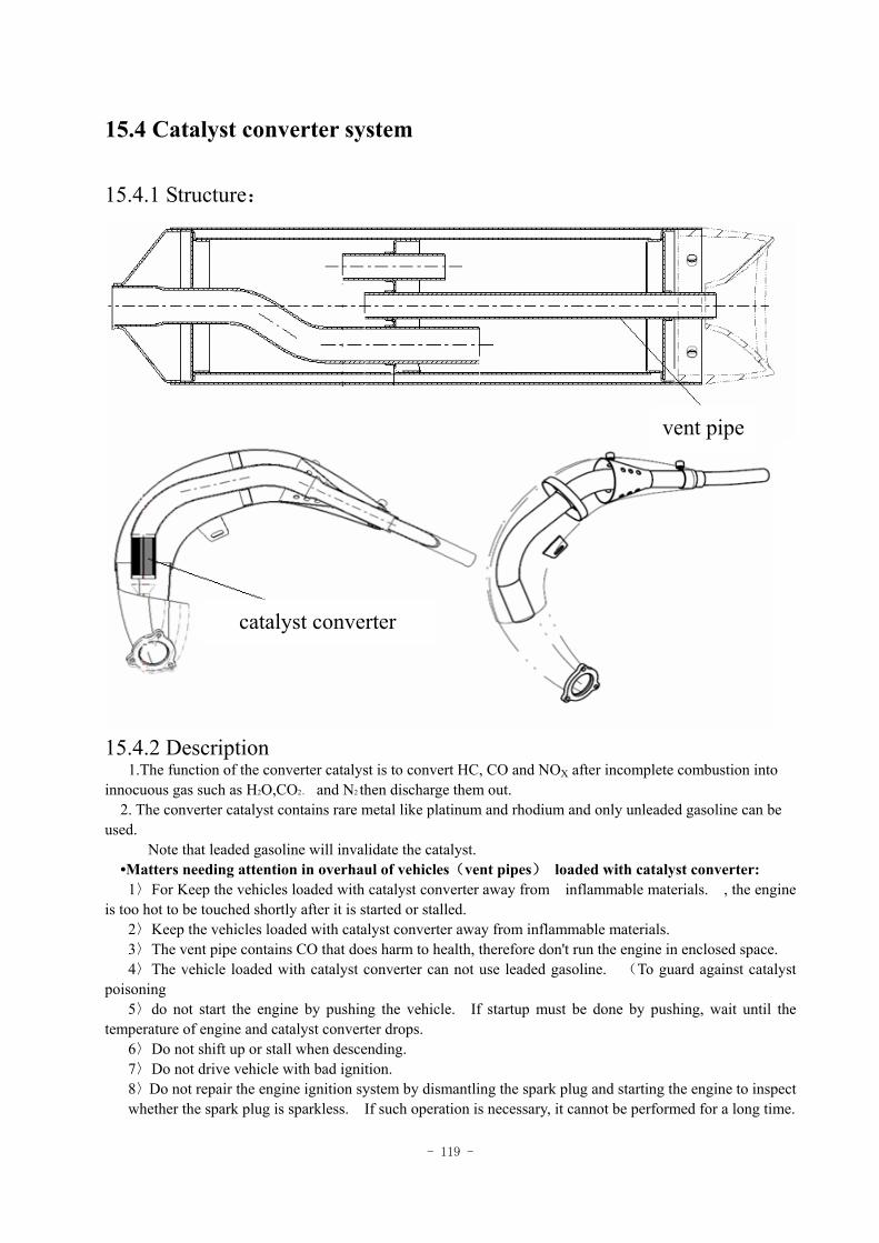
- 119 -
15.4 Catalyst converter system
15.4.1 Structure:
15.4.2 Description 1.The function of the converter catalyst is to convert HC, CO and NOX after incomplete combustion into innocuous gas such as H2O,CO2、 and N2 then discharge them out. 2. The converter catalyst contains rare metal like platinum and rhodium and only unleaded gasoline can be used.
Note that leaded gasoline will invalidate the catalyst. •Matters needing attention in overhaul of vehicles(vent pipes) loaded with catalyst converter: 1〉For Keep the vehicles loaded with catalyst converter away from inflammable materials. , the engine
is too hot to be touched shortly after it is started or stalled. 2〉Keep the vehicles loaded with catalyst converter away from inflammable materials. 3〉The vent pipe contains CO that does harm to health, therefore don't run the engine in enclosed space. 4〉The vehicle loaded with catalyst converter can not use leaded gasoline. (To guard against catalyst
poisoning 5〉do not start the engine by pushing the vehicle. If startup must be done by pushing, wait until the
temperature of engine and catalyst converter drops. 6〉Do not shift up or stall when descending. 7〉Do not drive vehicle with bad ignition. 8〉Do not repair the engine ignition system by dismantling the spark plug and starting the engine to inspect whether the spark plug is sparkless. If such operation is necessary, it cannot be performed for a long time.
vent pipe
catalyst converter
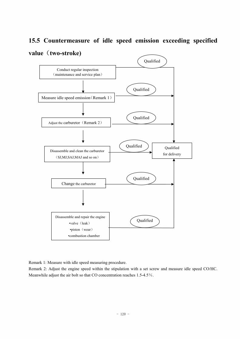
- 120 -
Conduct regular inspection (maintenance and service plan)
Measure idle speed emission(Remark 1)
Adjust the carburetor(Remark 2)
Disassemble and clean the carburetor
(SJ,MJ,SAJ,MAJ and so on)
Change the carburetor
Disassemble and repair the engine
•valve(leak)
•piston(wear)
•combustion chamber
Qualified
for delivery
Qualified
Qualified
Qualified
Qualified
Qualified
15.5 Countermeasure of idle speed emission exceeding specified
value(two-stroke)
Remark 1: Measure with idle speed measuring procedure. Remark 2: Adjust the engine speed within the stipulation with a set screw and measure idle speed CO/HC. Meanwhile adjust the air bolt so that CO concentration reaches 1.5-4.5%.
Qualified
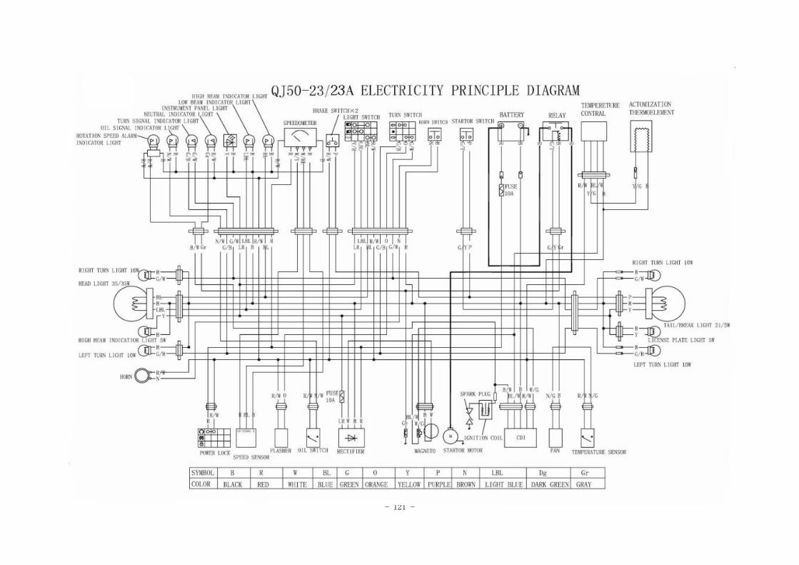
- 121 -