Embed Size (px)
Citation preview
Con
trol
boa
rds
and
cabi
nets
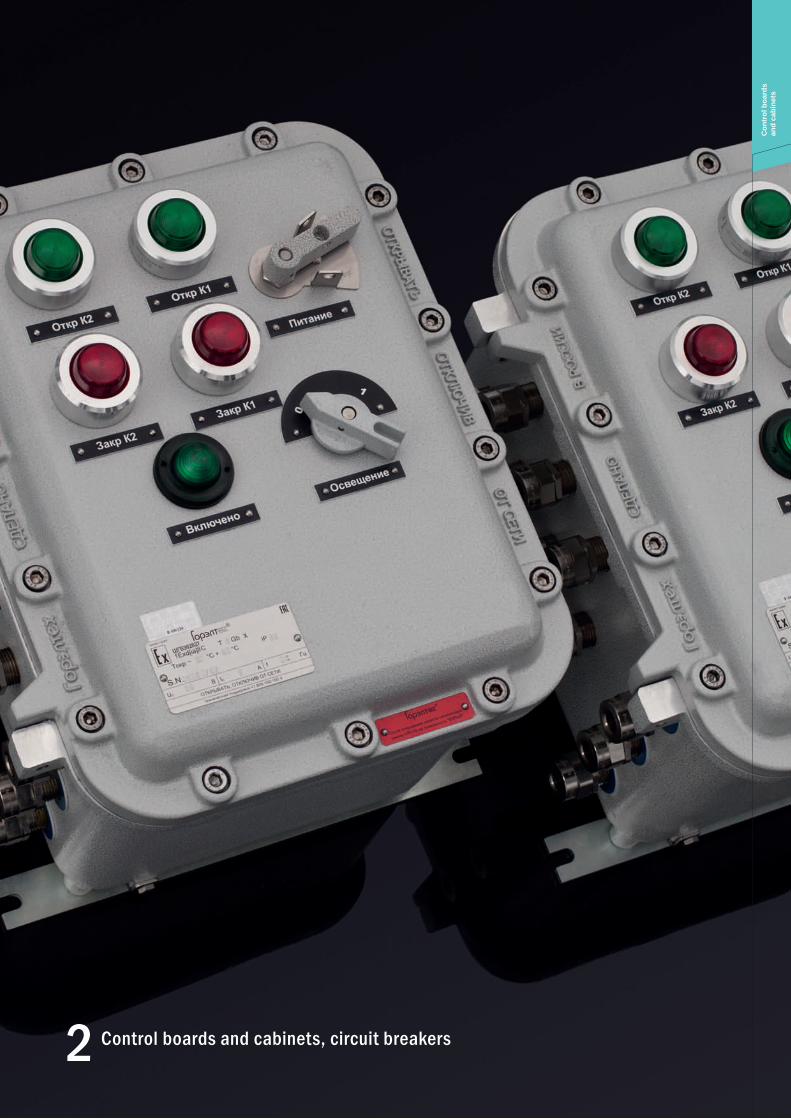
Control boards and cabinets, circuit breakers2
Control boards and cabinets, circuit breakersC
ontr
ol b
oard
s an
d ca
bine
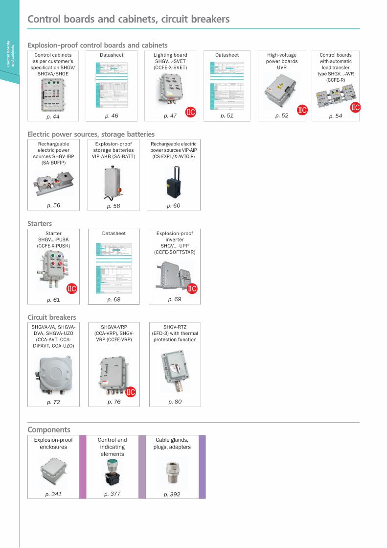
ts Explosion-proof control boards and cabinetsControl cabinets
as per customer’s specification SHGV/
SHGVA/SHGE
p. 44
Datasheet Назначение
Зона установки Зона 0 Зона 1 Зона 2 Исполнение PH Исполнение PB
PО PП Требуемый вид взрывозащиты ______________________Группа и подгруппа газовоздушной
смеси IIA IIB IIB+H2 IIC X IIC IIIC
Температурный класс Т4 Т5 T6 Температура эксплуатации T окр от _____ до _____
Защита IP IP66 (по умолчанию) IP65 IP67 IP68
Материал корпуса Коррозионностойкий алюминиево-кремниевый сплав Нержавеющая сталь
Полиэстр, армированный стекловолокном Малоуглеродистая сталь с порошковым покрытием
Способ установки Крепление на стену Напольная установка на раме Рама Другое ______________________Предусмотреть установку оборудования (автоматические выключатели, контакторы и др.)
Органы операционного управления и индикаторы
Размещение КИП
Кабельные вводы
Сторона расположения
Кол-во вводов на сторону
Диаметр внешней оболочки кабеля, мм
Диаметр внутренней оболочки кабеля, мм (только для
бронированного кабеля)
Тип кабельного ввода
Марка кабеля
A Б В Г
Опции, аксессуары и исполнения
Антиконденсатное покрытие /АП Дренажное устройство для слива конденсата /ДКУВ
Исполнение для тропиков с защитой от насекомых /ТЕРМИТЫ Морское исполнение /МОРЕ
Сейсмостойкое исполнение /МШК-64 Приемка заказчика /ПРИЕМКА
Окрашивание внешней поверхности в цвет по требованию заказчика /RAL (код)
Невзрывозащищённое исполнение, температура эксплуатации от –60 С до +80 С /ПРОМ
Обогрев /ОБОГРЕВ Внутренняя теплоизоляция /ТЕПЛОИЗОЛЯЦИЯ
Несущая рама. Скоба крепления по схеме заказчика /РАМА Исполнение для температуры эксплуатации –75°С /АНТАРКТИКА
Исполнение для оборудования постоянно эксплуатируемого при низких температурах /ХОЛОД
Количество, шт. штук
Примечания заказчика
Ограничение габаритов шкафа (если есть): _______Х_______ Х_______длина высота глубина
Контактная информация
Организация: Тел./факс:Почтовый адрес:Контактное лицо: E-mail:
p. 46
Lighting board SHGV…-SVET
(CCFE-X-SVET)
p. 47
Datasheet Назначение
Зона установки Зона 0 Зона 1 Зона 2 Исполнение PH Исполнение PB
PО PП Требуемый вид взрывозащиты ______________________Группа и подгруппа газовоздушной
смеси IIA IIB IIB+H2 IIC X IIC IIIC
Температурный класс Т4 Т5 T6 Температура эксплуатации T окр от _____ до _____
Защита IP IP66 (по умолчанию) IP65 IP67 IP68
Материал корпуса Коррозионностойкий алюминиево-кремниевый сплав Нержавеющая сталь
Полиэстр, армированный стекловолокном Малоуглеродистая сталь с порошковым покрытием
Способ установки Крепление на стену Напольная установка на раме Рама Другое ______________________Предусмотреть установку оборудования (автоматические выключатели, контакторы и др.)
Органы операционного управления и индикаторы
Размещение КИП
Кабельные вводы
Сторона расположения
Кол-во вводов на сторону
Диаметр внешней оболочки кабеля, мм
Диаметр внутренней оболочки кабеля, мм (только для
бронированного кабеля)
Тип кабельного ввода
Марка кабеля
A Б В Г
Опции, аксессуары и исполнения
Антиконденсатное покрытие /АП Дренажное устройство для слива конденсата /ДКУВ
Исполнение для тропиков с защитой от насекомых /ТЕРМИТЫ Морское исполнение /МОРЕ
Сейсмостойкое исполнение /МШК-64 Приемка заказчика /ПРИЕМКА
Окрашивание внешней поверхности в цвет по требованию заказчика /RAL (код)
Невзрывозащищённое исполнение, температура эксплуатации от –60 С до +80 С /ПРОМ
Обогрев /ОБОГРЕВ Внутренняя теплоизоляция /ТЕПЛОИЗОЛЯЦИЯ
Несущая рама. Скоба крепления по схеме заказчика /РАМА Исполнение для температуры эксплуатации –75°С /АНТАРКТИКА
Исполнение для оборудования постоянно эксплуатируемого при низких температурах /ХОЛОД
Количество, шт. штук
Примечания заказчика
Ограничение габаритов шкафа (если есть): _______Х_______ Х_______длина высота глубина
Контактная информация
Организация: Тел./факс:Почтовый адрес:Контактное лицо: E-mail:
p. 51
High-voltage power boards
UVR
p. 52
Control boards with automatic load transfer
type SHGV…-AVR (CCFE-R)
p. 54
Electric power sources, storage batteriesRechargeable electric power
sources SHGV-IBP (SA-BUFIP)
p. 56
Explosion-proof storage batteries
VIP-AKB (SA-BATT)
p. 58
Rechargeable electric power sources VIP-AIP (CS-EXPL/X-AVTOIP)
p. 60
StartersStarter
SHGV…-PUSK (CCFE-X-PUSK)
p. 61
Datasheet
Назначение
Зона установки Зона 0 Зона 1 Зона 2 Исполнение PH Исполнение PB
PО PП Требуемый вид взрывозащиты ______________________Группа и подгруппа газовоздушной
смеси IIA IIB IIB+H2 IIC X IIC IIIC
Температурный класс Т4 Т5 T6 Температура эксплуатации T окр от _____ до _____
Защита IP IP66 (по умолчанию) IP65 IP67 IP68
Материал корпуса Коррозионностойкий алюминиево-кремниевый сплав Нержавеющая сталь
Полиэстр, армированный стекловолокном Малоуглеродистая сталь с порошковым покрытием
Способ установки Крепление на стену Напольная установка на раме Рама Другое ______________________Предусмотреть установку оборудования (автоматические выключатели, контакторы и др.)
Органы операционного управления и индикаторы
Размещение КИП
Кабельные вводы
Сторона расположения
Кол-во вводов на сторону
Диаметр внешней оболочки кабеля, мм
Диаметр внутренней оболочки кабеля, мм (только для
бронированного кабеля)
Тип кабельного ввода
Марка кабеля
A Б В Г
Опции, аксессуары и исполнения
Антиконденсатное покрытие /АП Дренажное устройство для слива конденсата /ДКУВ
Исполнение для тропиков с защитой от насекомых /ТЕРМИТЫ Морское исполнение /МОРЕ
Сейсмостойкое исполнение /МШК-64 Приемка заказчика /ПРИЕМКА
Окрашивание внешней поверхности в цвет по требованию заказчика /RAL (код)
Невзрывозащищённое исполнение, температура эксплуатации от –60 С до +80 С /ПРОМ
Обогрев /ОБОГРЕВ Внутренняя теплоизоляция /ТЕПЛОИЗОЛЯЦИЯ
Несущая рама. Скоба крепления по схеме заказчика /РАМА Исполнение для температуры эксплуатации –75°С /АНТАРКТИКА
Исполнение для оборудования постоянно эксплуатируемого при низких температурах /ХОЛОД
Количество, шт. штук
Примечания заказчика
Ограничение габаритов шкафа (если есть): _______Х_______ Х_______длина высота глубина
Контактная информация
Организация: Тел./факс:Почтовый адрес:Контактное лицо: E-mail:
p. 68
Explosion-proof inverter
SHGV…-UPP (CCFE-SOFTSTAR)
p. 69
Circuit breakersSHGVA-VA, SHGVA-DVA, SHGVA-UZO (CCA-AVT, CCA-
DIFAVT, CCA-UZO)
p. 72
SHGVA-VRP (CCA-VRP), SHGV-VRP (CCFE-VRP)
p. 76
SHGV-RTZ (EFD-3) with thermal protection function
p. 80
ComponentsExplosion-proof
enclosures
p. 341
Control and indicating elements
p. 377
Cable glands, plugs, adapters
p. 392
Con
trol
boa
rds
and
cabi
nets
44
Control boards as per customer’s specification SHGV/SHGVA/SHGEC
ontr
ol b
oard
s an
d ca
bine
ts
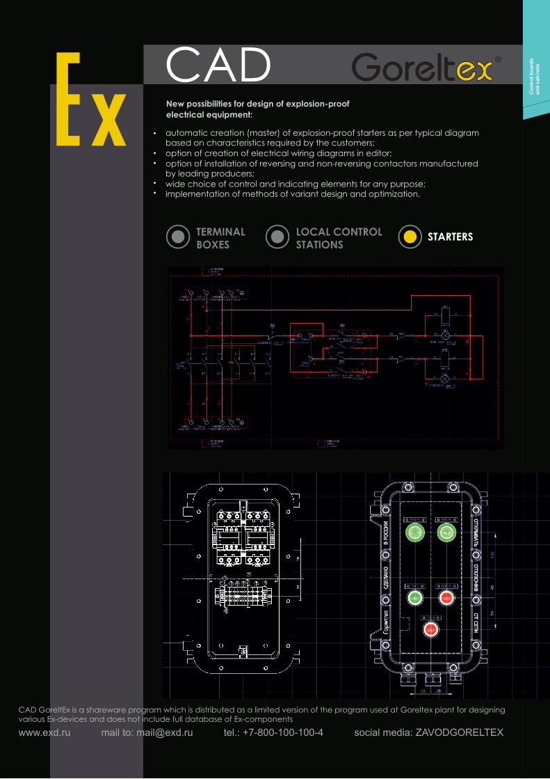
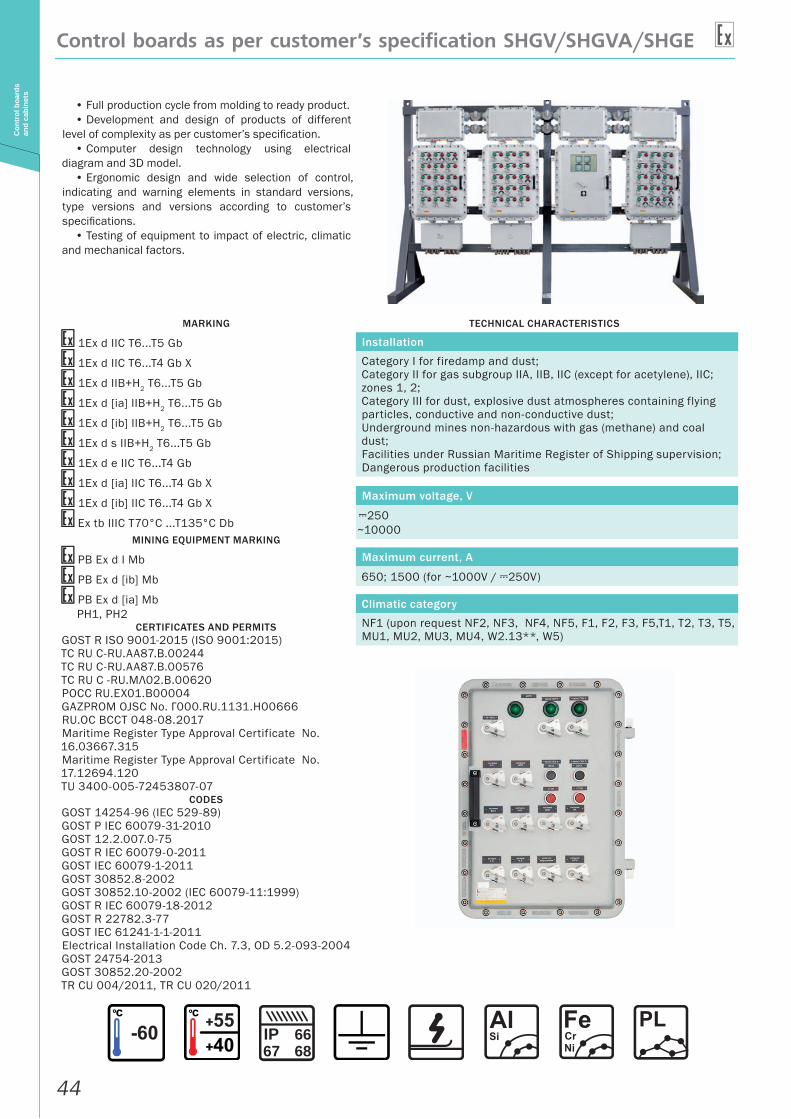
• Full production cycle from molding to ready product.• Development and design of products of different
level of complexity as per customer’s specification.• Computer design technology using electrical
diagram and 3D model.• Ergonomic design and wide selection of control,
indicating and warning elements in standard versions, type versions and versions according to customer’s specifications.
• Testing of equipment to impact of electric, climatic and mechanical factors.
MARKING
1Ex d IIC T6...T5 Gb
1Ex d IIС T6...T4 Gb X
1Ex d IIB+H2 T6...T5 Gb
1Ex d [ia] IIB+H2 T6...T5 Gb
1Ex d [ib] IIB+H2 T6...T5 Gb
1Ex d s IIB+H2 T6...T5 Gb
1Ex d e IIC T6...T4 Gb
1Ex d [ia] IIC T6...T4 Gb X
1Ex d [ib] IIC T6...T4 Gb X
Ex tb IIIC T70°C ...T135°C DbMINING EQUIPMENT MARKING
PB Ex d I Mb
PB Ex d [ib] Mb
PB Ex d [ia] MbРН1, РН2
CERTIFICATES AND PERMITSGOST R ISO 9001-2015 (ISO 9001:2015)ТС RU С-RU.AA87.В.00244ТС RU С-RU.AA87.В.00576TC RU C -RU.МЛ02.B.00620РОСС RU.EX01.B00004GAZPROM OJSC No. Г000.RU.1131.H00666RU.OC BCCT 048-08.2017Maritime Register Type Approval Certificate No. 16.03667.315Maritime Register Type Approval Certificate No. 17.12694.120TU 3400-005-72453807-07
CODESGOST 14254-96 (IEC 529-89)GOST Р IEC 60079-31-2010GOST 12.2.007.0-75GOST R IEC 60079-0-2011GOST IEC 60079-1-2011GOST 30852.8-2002GOST 30852.10-2002 (IEC 60079-11:1999)GOST R IEC 60079-18-2012GOST R 22782.3-77GOST IEC 61241-1-1-2011Electrical Installation Code Ch. 7.3, OD 5.2-093-2004GOST 24754-2013GOST 30852.20-2002TR CU 004/2011, TR CU 020/2011
TECHNICAL CHARACTERISTICS
Installation
Category I for firedamp and dust;Category II for gas subgroup IIA, IIB, IIC (except for acetylene), IIC; zones 1, 2;Category III for dust, explosive dust atmospheres containing flying particles, conductive and non-conductive dust;Underground mines non-hazardous with gas (methane) and coal dust;Facilities under Russian Maritime Register of Shipping supervision;Dangerous production facilities
Maximum voltage, V
A250~10000
Maximum current, A
650; 1500 (for ~1000V / A250V)
Climatic category
NF1 (upon request NF2, NF3, NF4, NF5, F1, F2, F3, F5,T1, T2, T3, T5, MU1, MU2, MU3, MU4, W2.13**, W5)
IP 6667 68
45
Control boards as per customer’s specification SHGV/SHGVA/SHGE
Con
trol
boa
rds
and
cabi
nets
OPTIONS, ACCESSORIES AND VERSIONS
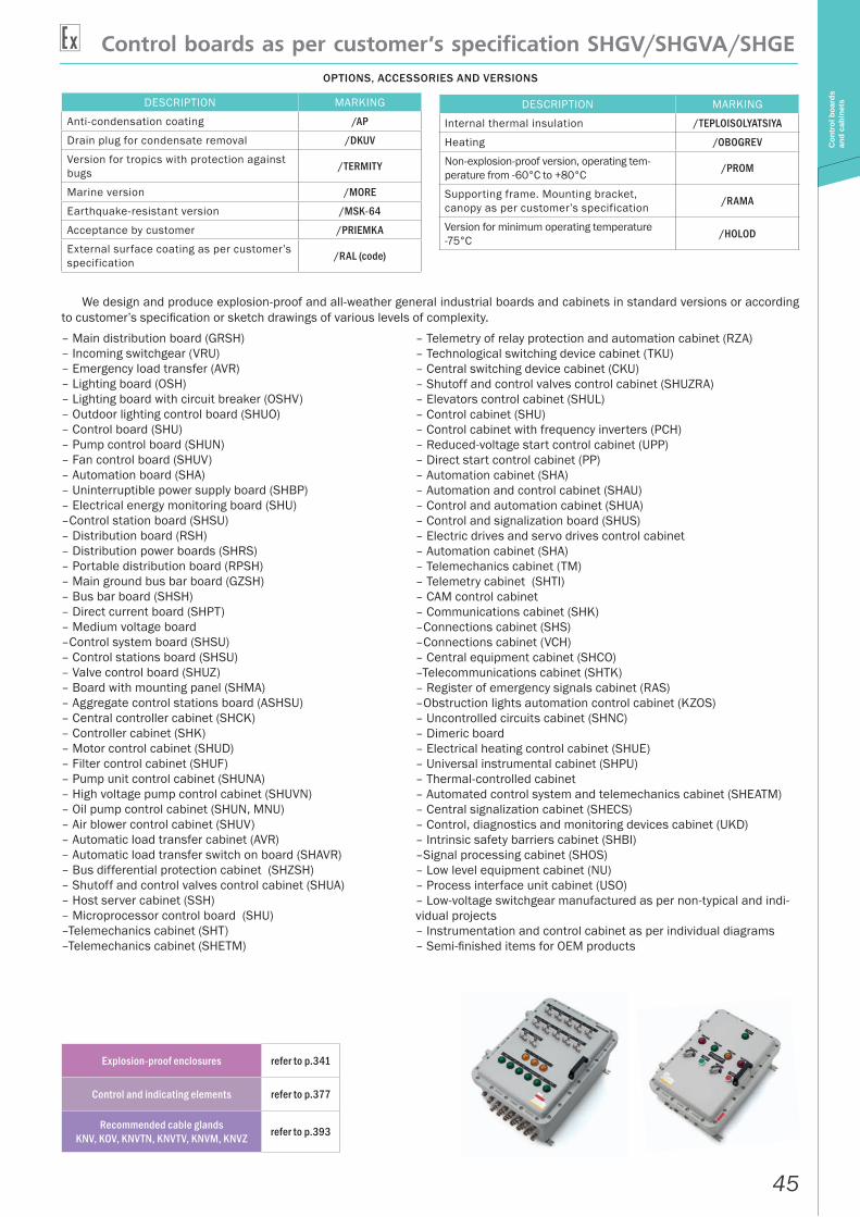
We design and produce explosion-proof and all-weather general industrial boards and cabinets in standard versions or according to customer’s specification or sketch drawings of various levels of complexity.– Main distribution board (GRSH)– Incoming switchgear (VRU)– Emergency load transfer (AVR)– Lighting board (OSH)– Lighting board with circuit breaker (OSHV)– Outdoor lighting control board (SHUO)– Control board (SHU)– Pump control board (SHUN)– Fan control board (SHUV)– Automation board (SHA)– Uninterruptible power supply board (SHBP)– Electrical energy monitoring board (SHU)–Control station board (SHSU)– Distribution board (RSH)– Distribution power boards (SHRS)– Portable distribution board (RPSH)– Main ground bus bar board (GZSH)– Bus bar board (SHSH)– Direct current board (SHPT)– Medium voltage board–Control system board (SHSU)– Control stations board (SHSU)– Valve control board (SHUZ)– Board with mounting panel (SHMA)– Aggregate control stations board (ASHSU)– Central controller cabinet (SHCK)– Controller cabinet (SHK)– Motor control cabinet (SHUD)– Filter control cabinet (SHUF)– Pump unit control cabinet (SHUNA)– High voltage pump control cabinet (SHUVN)– Oil pump control cabinet (SHUN, MNU)– Air blower control cabinet (SHUV)– Automatic load transfer cabinet (AVR)– Automatic load transfer switch on board (SHAVR)– Bus differential protection cabinet (SHZSH)– Shutoff and control valves control cabinet (SHUA)– Host server cabinet (SSH)– Microprocessor control board (SHU)–Telemechanics cabinet (SHT)–Telemechanics cabinet (SHETM)
– Telemetry of relay protection and automation cabinet (RZA)– Technological switching device cabinet (TKU)– Central switching device cabinet (CKU)– Shutoff and control valves control cabinet (SHUZRA)– Elevators control cabinet (SHUL)– Control cabinet (SHU)– Control cabinet with frequency inverters (PCH)– Reduced-voltage start control cabinet (UPP)– Direct start control cabinet (PP)– Automation cabinet (SHA)– Automation and control cabinet (SHAU)– Control and automation cabinet (SHUA)– Control and signalization board (SHUS)– Electric drives and servo drives control cabinet– Automation cabinet (SHA)– Telemechanics cabinet (TM)– Telemetry cabinet (SHTI)– CAM control cabinet– Communications cabinet (SHK)–Connections cabinet (SHS)–Connections cabinet (VCH)– Central equipment cabinet (SHCO)–Telecommunications cabinet (SHTK)– Register of emergency signals cabinet (RAS)–Obstruction lights automation control cabinet (KZOS)– Uncontrolled circuits cabinet (SHNC)– Dimeric board– Electrical heating control cabinet (SHUE)– Universal instrumental cabinet (SHPU)– Thermal-controlled cabinet – Automated control system and telemechanics cabinet (SHEATM)– Central signalization cabinet (SHECS)– Control, diagnostics and monitoring devices cabinet (UKD)– Intrinsic safety barriers cabinet (SHBI)–Signal processing cabinet (SHOS)– Low level equipment cabinet (NU)– Process interface unit cabinet (USO)– Low-voltage switchgear manufactured as per non-typical and indi-vidual projects– Instrumentation and control cabinet as per individual diagrams– Semi-finished items for OEM products
DESCRIPTION MARKING
Anti-condensation coating /AP
Drain plug for condensate removal /DKUV
Version for tropics with protection against bugs /TERMITY
Marine version /MORE
Earthquake-resistant version /MSK-64
Acceptance by customer /PRIEMKA
External surface coating as per customer’s specification /RAL (code)
DESCRIPTION MARKING
Internal thermal insulation /TEPLOISOLYATSIYA
Heating /OBOGREV
Non-explosion-proof version, operating tem-perature from -60°C to +80°C /PROM
Supporting frame. Mounting bracket, canopy as per customer’s specification /RAMA
Version for minimum operating temperature -75°C /HOLOD
Explosion-proof enclosures refer to p.341
Control and indicating elements refer to p.377
Recommended cable glands KNV, KOV, KNVTN, KNVTV, KNVM, KNVZ refer to p.393
46
DatasheetC
ontr
ol b
oard
s an
d ca
bine
ts
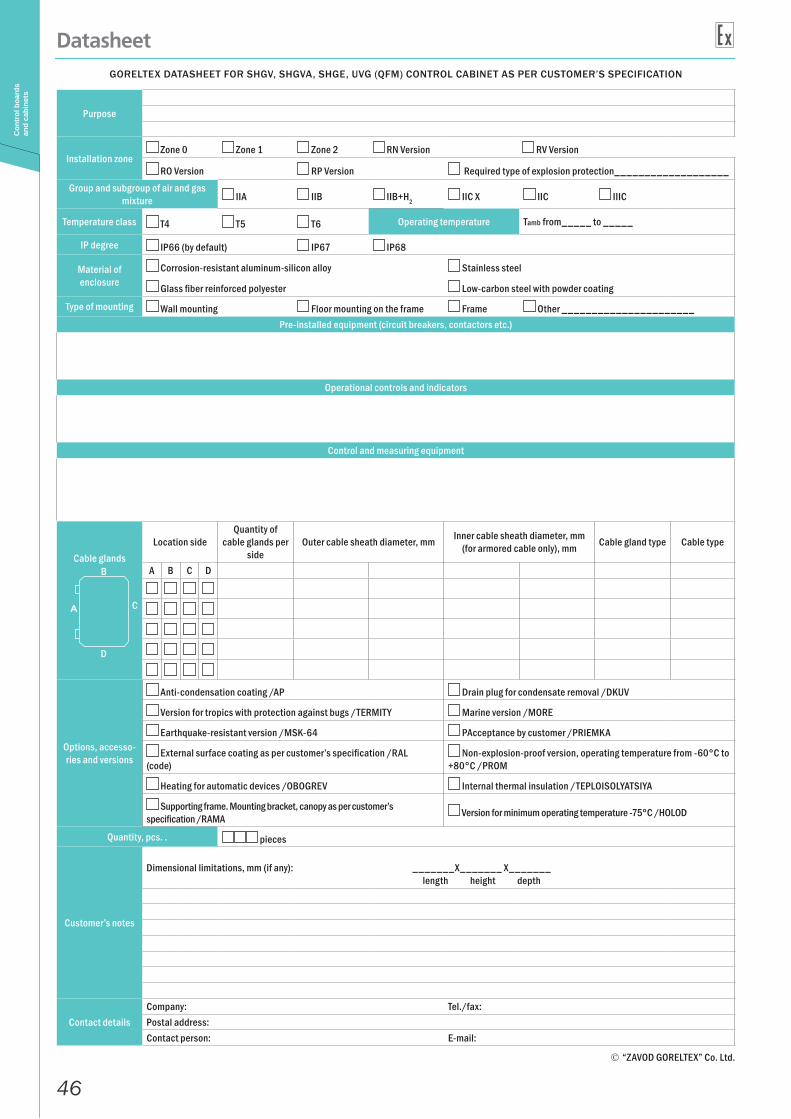
GORELTEX DATASHEET FOR SHGV, SHGVA, SHGE, UVG (QFM) CONTROL CABINET AS PER CUSTOMER’S SPECIFICATION
Purpose
Installation zone Zone 0 Zone 1 Zone 2 RN Version RV Version
RO Version RP Version Required type of explosion protection___________________Group and subgroup of air and gas
mixture IIA IIB IIB+H2 IIC X IIC IIIC
Temperature class Т4 Т5 T6 Operating temperature Tamb from_____ to _____
IP degree IP66 (by default) IP67 IP68
Material of enclosure
Corrosion-resistant aluminum-silicon alloy Stainless steel
Glass fiber reinforced polyester Low-carbon steel with powder coating
Type of mounting Wall mounting Floor mounting on the frame Frame Other ______________________Pre-installed equipment (circuit breakers, contactors etc.)
Operational controls and indicators
Control and measuring equipment
Cable glandsLocation side
Quantity of cable glands per
sideOuter cable sheath diameter, mm Inner cable sheath diameter, mm
(for armored cable only), mm Cable gland type Cable type
A B C D
Options, accesso-ries and versions
Anti-condensation coating /AP Drain plug for condensate removal /DKUV
Version for tropics with protection against bugs /TERMITY Marine version /MORE
Earthquake-resistant version /MSK-64 PAcceptance by customer /PRIEMKA
External surface coating as per customer’s specification /RAL (code)
Non-explosion-proof version, operating temperature from -60°C to +80°C /PROM
Heating for automatic devices /OBOGREV Internal thermal insulation /TEPLOISOLYATSIYA
Supporting frame. Mounting bracket, canopy as per customer’s specification /RAMA Version for minimum operating temperature -75°C /HOLOD
Quantity, pcs. . pieces
Customer’s notes
Dimensional limitations, mm (if any): _______Х_______ Х_______length height depth
Contact detailsCompany: Tel./fax:Postal address:Contact person: E-mail:
“ZAVOD GORELTEX” Co. Ltd.
B
C
D
47
SHGV-SVET CCFE-X-SVET
Con
trol
boa
rds
and
cabi
nets
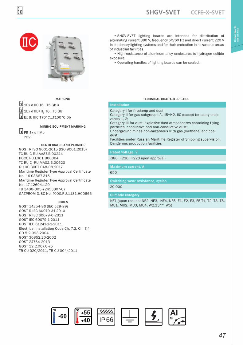
• SHGV-SVET lighting boards are intended for distribution of alternating current 380 V, frequency 50/60 Hz and direct current 220 V in stationary lighting systems and for their protection in hazardous areas of industrial facilities.
• High resistance of aluminum alloy enclosures to hydrogen sulfide exposure.
• Operating handles of lighting boards can be sealed.
MARKING
1Ex d IIC T6...T5 Gb X
1Ex d IIB+H2 T6...T5 Gb
Ex tb IIIC T70°С...T100°С Db
MINING EQUIPMENT MARKING
РВ Ex d I MbРН2
CERTIFICATES AND PERMITSGOST R ISO 9001-2015 (ISO 9001:2015)ТС RU С-RU.AA87.В.00244РОСС RU.EX01.B00004TC RU C -RU.МЛ02.B.00620RU.OC BCCT 048-08.2017Maritime Register Type Approval Certificate No. 16.03667.315Maritime Register Type Approval Certificate No. 17.12694.120TU 3400-005-72453807-07GAZPROM OJSC No. Г000.RU.1131.H00666
CODESGOST 14254-96 (IEC 529-89)GOST R IEC 60079-31-2010GOST R IEC 60079-0-2011GOST IEC 60079-1-2011GOST IEC 61241-1-1-2011Electrical Installation Code Ch. 7.3, Ch. 7.4OD 5.2-093-2004GOST 30852.20-2002GOST 24754-2013GOST 12.2.007.0-75TR CU 020/2011, TR CU 004/2011
TECHNICAL CHARACTERISTICS
Installation
Category I for firedamp and dust;Category II for gas subgroup IIA, IIB+H2, IIC (except for acetylene); zones 1, 2;Category III for dust, explosive dust atmospheres containing flying particles, conductive and non-conductive dust;Underground mines non-hazardous with gas (methane) and coal dust;Facilities under Russian Maritime Register of Shipping supervision;Dangerous production facilities
Rated voltage, V
~380, ~220 (A220 upon approval)
Maximum current, A
650
Switching wear-resistance, cycles
20 000
Climatic category
NF1 (upon request NF2, NF3, NF4, NF5, F1, F2, F3, F5,T1, T2, T3, T5, MU1, MU2, MU3, MU4, W2.13**, W5)
66IP
48
SHGV-SVET CCFE-X-SVET
Con
trol
boa
rds
and
cabi
nets
OPTIONS, ACCESSORIES AND VERSIONS
DESCRIPTION MARKING
Anti-condensation coating /AP
Marine version /MORE
Drain plug for condensate removal /DKUV
Version for tropics with protection against bugs /TERMITY
Earthquake-resistant version /MSK-64
Acceptance by customer /PRIEMKA
External surface coating as per customer’s specification /RAL (code)
Material of enclosure: highly corrosion-resistant chrome-nickel stainless casting steel /N
Internal thermal insulation /TEPLOISOLYATSIYA
Heating /OBOGREV
Remote light sensor of twilight switch /DS
Supporting frame. Mounting bracket as per customer’s specification /RAMA
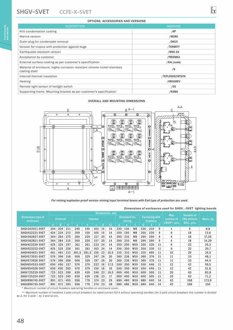
OVERALL AND MOUNTING DIMENSIONS
For mining explosion-proof version mining input terminal boxes with Exd type of protection are used.
Dimensions of enclosures used for SHGV…-SVET lighting boards
Dimension type of enclosure
Dimensions, mmMax.
number of CBOH*, pcs.
Number of CBs without
OHs., pcs.Mass, kgExternal Internal Standard fas-
teningFastening with
bracketsA B C a b c S S1 d e f D E F
SHGV302021-SVET 304 204 211 240 140 163 14 14 230 130 М8 230 210 9 1 5 8,8SHGV422221-SVET 424 224 213 359 159 165 15 14 350 150 М8 350 230 9 6 18 13,6SHGV362827-SVET 364 284 275 300 220 217 20 14 290 210 М8 290 290 9 4 18 17,25SHGV362821-SVET 364 284 215 300 220 157 20 14 290 210 М8 290 290 9 4 18 14,29SHGV423229-SVET 425 325 297 361 261 233 24 14 350 250 М10 350 330 11 6 22 25,3SHGV423222-SVET 425 325 226 361 261 163 24 14 350 350 M10 350 330 11 6 22 20,7SHGV464621-SVET 461 461 213 391,5 391,5 150 22 16,5 310 310 M10 310 460 11 10 29 34,5SHGV573931-SVET 576 396 318 506 329 247 26 20 360 236 М10 360 376 11 11 33 48,1SHGV573926-SVET 576 396 268 506 326 197 26 20 360 236 М10 360 376 11 11 33 44,4SHGV654533-SVET 650 450 337 570 370 222 16 17,5 550 350 М10 550 446 11 12 42 59,5SHGV654526-SVET 650 450 265 570 370 150 16 16 550 350 M10 550 446 11 12 42 51,6SHGV725235-SVET 723 523 359 639 439 246 23 18,5 600 400 M10 600 505 11 20 63 83,8SHGV725224-SVET 723 523 249 639 439 136 23 17 600 400 M10 600 505 11 20 63 71,2SHGV896745-SVET 891 671 455 556 776 374 23 29 680 480 M16 680 640 14 42 168 173,9SHGV896735-SVET 891 671 355 556 776 274 23 28 680 480 M16 680 640 14 42 168 150* Maximum number of circuit breakers operating handles on enclosure cover.** Maximum number of installed 1-pole circuit breakers for rated current 63 A without operating handles (for 2-pole circuit breakers this number is divided
by 2, for 3-pole – by 3 and so on).
49
SHGV-SVET CCFE-X-SVET
Con
trol
boa
rds
and
cabi
nets
Control and indicating elements refer to p.377
Recommended cable glands KNV, KOV, KNVTN, KNVTV, KNVM, KNVZ refer to p.393
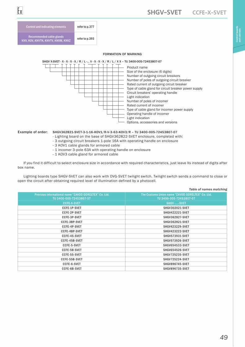
FORMATION OF MARKING
SHGV X-SVET - X - X - X - X / R / L -... V - X - X - X / R / L / X X – TU 3400-005-72453807-07
Product nameSize of the enclosure (6 digits)Number of outgoing circuit breakersNumber of poles of outgoing circuit breakerRated current of outgoing circuit breakerType of cable gland for circuit breaker power supplyCircuit breakers’ operating handleLight indicationNumber of poles of incomerRated current of incomerType of cable gland for incomer power supplyOperating handle of incomerLight indicationOptions, accessories and versions
Example of order: SHGV362821-SVET-3-1-16-KOV1/R-V-3-63-KOV3/R – TU 3400-005-72453807-07-- Lighting board on the base of SHGV362822-SVET enclosure, completed with:-- 3 outgoing circuit breakers 1-pole 16A with operating handle on enclosure-- 3 KOV1 cable glands for armored cable-- 1 incomer 3-pole 63A with operating handle on enclosure-- 1 KOV3 cable gland for armored cable
If you find it difficult to select enclosure size in accordance with required characteristics, just leave Xs instead of digits after box name.
Lighting boards type SHGV-SVET can also work with DVG-SVET twilight switch. Twilight switch sends a command to close or open the circuit after obtaining required level of illumination defined by a photocell.
Table of names matching
Previous international name “ZAVOD GORELTEX” Co. Ltd.TU 3400-005-72453807-07
The Customs Union name “ZAVOD GORELTEX” Co. Ltd.TU 3400-005-72453807-07
CCFE-X-SVET SHGV -...-SVETCCFE-1P-SVET SHGV302021-SVETCCFE-2P-SVET SHGV422221-SVETCCFE-3P-SVET SHGV362827-SVET
CCFE-3BP-SVET SHGV362821-SVETCCFE-4P-SVET SHGV423229-SVET
CCFE-4BP-SVET SHGV423222-SVETCCFE-45-SVET SHGV573931-SVET
CCFE-45B-SVET SHGV573926-SVETCCFE-5-SVET SHGV654533-SVET
CCFE-5B-SVET SHGV654526-SVETCCFE-55-SVET SHGV725235-SVET
CCFE-55B-SVET SHGV725224-SVETCCFE-6-SVET SHGV896745-SVET
CCFE-6B-SVET SHGV896735-SVET
50
SHGV-SVET CCFE-X-SVET
Con
trol
boa
rds
and
cabi
nets
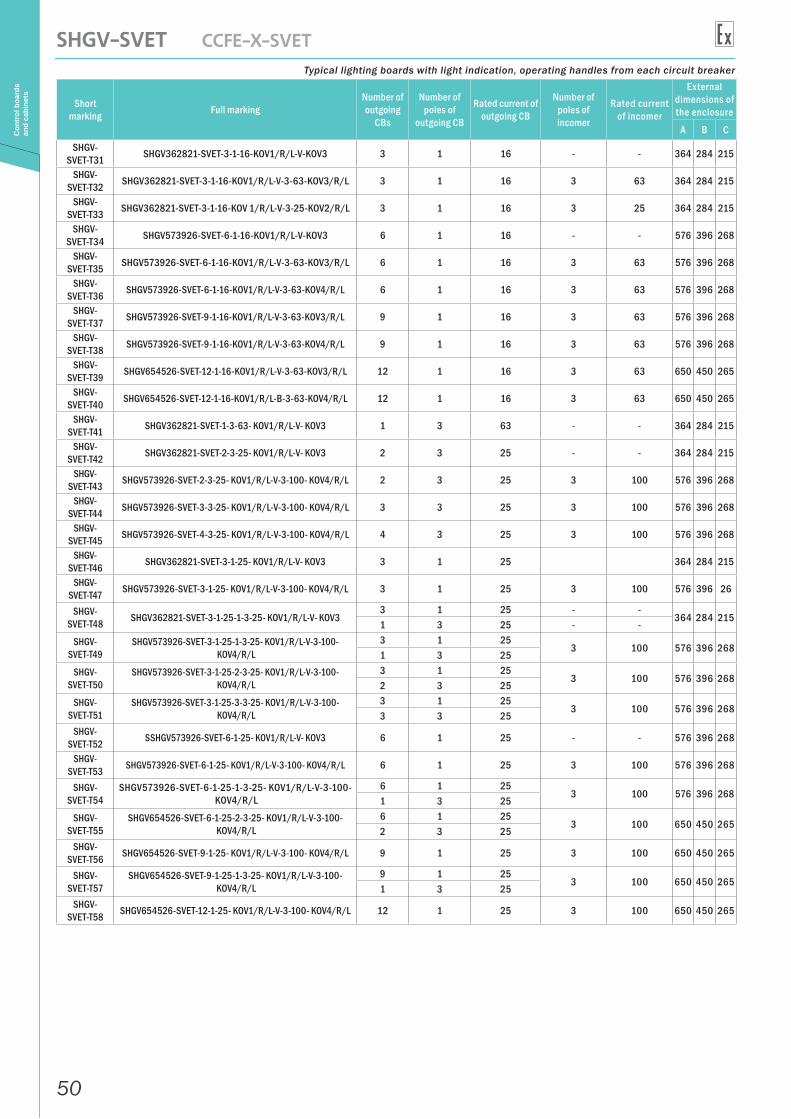
Typical lighting boards with light indication, operating handles from each circuit breaker
Short marking Full marking
Number of outgoing
CBs
Number of poles of
outgoing CB
Rated current of outgoing CB
Number of poles of incomer
Rated current of incomer
External dimensions of the enclosure
A B C
SHGV-SVET-Т31 SHGV362821-SVET-3-1-16-KOV1/R/L-V-KOV3 3 1 16 - - 364 284 215
SHGV-SVET-Т32 SHGV362821-SVET-3-1-16-KOV1/R/L-V-3-63-KOV3/R/L 3 1 16 3 63 364 284 215
SHGV-SVET-Т33 SHGV362821-SVET-3-1-16-KOV 1/R/L-V-3-25-KOV2/R/L 3 1 16 3 25 364 284 215
SHGV-SVET-Т34 SHGV573926-SVET-6-1-16-KOV1/R/L-V-KOV3 6 1 16 - - 576 396 268
SHGV-SVET-Т35 SHGV573926-SVET-6-1-16-KOV1/R/L-V-3-63-KOV3/R/L 6 1 16 3 63 576 396 268
SHGV-SVET-Т36 SHGV573926-SVET-6-1-16-KOV1/R/L-V-3-63-KOV4/R/L 6 1 16 3 63 576 396 268
SHGV-SVET-Т37 SHGV573926-SVET-9-1-16-KOV1/R/L-V-3-63-KOV3/R/L 9 1 16 3 63 576 396 268
SHGV-SVET-Т38 SHGV573926-SVET-9-1-16-KOV1/R/L-V-3-63-KOV4/R/L 9 1 16 3 63 576 396 268
SHGV-SVET-Т39 SHGV654526-SVET-12-1-16-KOV1/R/L-V-3-63-KOV3/R/L 12 1 16 3 63 650 450 265
SHGV-SVET-Т40 SHGV654526-SVET-12-1-16-KOV1/R/L-B-3-63-KOV4/R/L 12 1 16 3 63 650 450 265
SHGV-SVET-Т41 SHGV362821-SVET-1-3-63- KOV1/R/L-V- KOV3 1 3 63 - - 364 284 215
SHGV-SVET-Т42 SHGV362821-SVET-2-3-25- KOV1/R/L-V- KOV3 2 3 25 - - 364 284 215
SHGV-SVET-Т43 SHGV573926-SVET-2-3-25- KOV1/R/L-V-3-100- KOV4/R/L 2 3 25 3 100 576 396 268
SHGV-SVET-Т44 SHGV573926-SVET-3-3-25- KOV1/R/L-V-3-100- KOV4/R/L 3 3 25 3 100 576 396 268
SHGV-SVET-Т45 SHGV573926-SVET-4-3-25- KOV1/R/L-V-3-100- KOV4/R/L 4 3 25 3 100 576 396 268
SHGV-SVET-Т46 SHGV362821-SVET-3-1-25- KOV1/R/L-V- KOV3 3 1 25 364 284 215
SHGV-SVET-Т47 SHGV573926-SVET-3-1-25- KOV1/R/L-V-3-100- KOV4/R/L 3 1 25 3 100 576 396 26
SHGV-SVET-Т48 SHGV362821-SVET-3-1-25-1-3-25- KOV1/R/L-V- KOV3
3 1 25 - -364 284 215
1 3 25 - -SHGV-
SVET-Т49SHGV573926-SVET-3-1-25-1-3-25- KOV1/R/L-V-3-100-
KOV4/R/L3 1 25
3 100 576 396 2681 3 25
SHGV-SVET-Т50
SHGV573926-SVET-3-1-25-2-3-25- KOV1/R/L-V-3-100- KOV4/R/L
3 1 253 100 576 396 268
2 3 25SHGV-
SVET-Т51SHGV573926-SVET-3-1-25-3-3-25- KOV1/R/L-V-3-100-
KOV4/R/L3 1 25
3 100 576 396 2683 3 25
SHGV-SVET-Т52 SSHGV573926-SVET-6-1-25- KOV1/R/L-V- KOV3 6 1 25 - - 576 396 268
SHGV-SVET-Т53 SHGV573926-SVET-6-1-25- KOV1/R/L-V-3-100- KOV4/R/L 6 1 25 3 100 576 396 268
SHGV-SVET-Т54
SHGV573926-SVET-6-1-25-1-3-25- KOV1/R/L-V-3-100- KOV4/R/L
6 1 253 100 576 396 268
1 3 25SHGV-
SVET-Т55SHGV654526-SVET-6-1-25-2-3-25- KOV1/R/L-V-3-100-
KOV4/R/L6 1 25
3 100 650 450 2652 3 25
SHGV-SVET-Т56 SHGV654526-SVET-9-1-25- KOV1/R/L-V-3-100- KOV4/R/L 9 1 25 3 100 650 450 265
SHGV-SVET-Т57
SHGV654526-SVET-9-1-25-1-3-25- KOV1/R/L-V-3-100- KOV4/R/L
9 1 253 100 650 450 265
1 3 25SHGV-
SVET-Т58 SHGV654526-SVET-12-1-25- KOV1/R/L-V-3-100- KOV4/R/L 12 1 25 3 100 650 450 265
51
Datasheet
Con
trol
boa
rds
and
cabi
nets
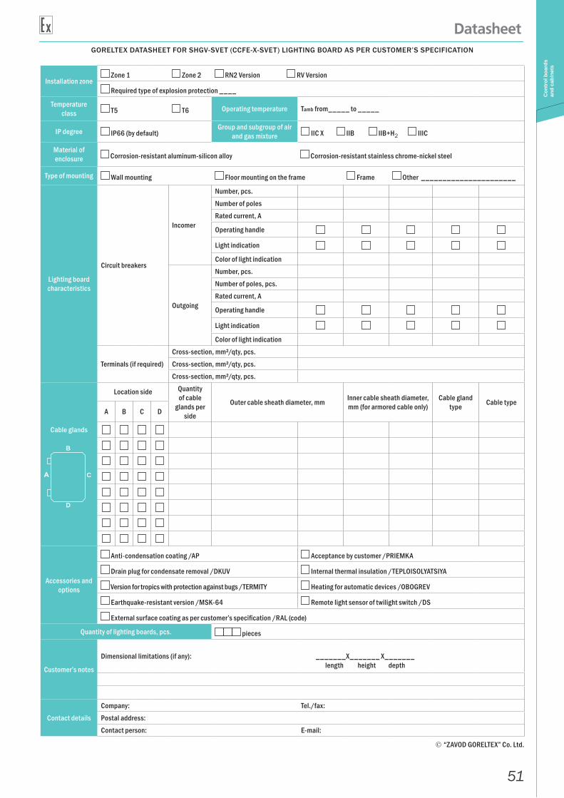
GORELTEX DATASHEET FOR SHGV-SVET (CCFE-X-SVET) LIGHTING BOARD AS PER CUSTOMER’S SPECIFICATION
Installation zone Zone 1 Zone 2 RN2 Version RV Version
Required type of explosion protection ____
Temperature class Т5 T6 Operating temperature Tamb from_____ to _____
IP degree IP66 (by default)Group and subgroup of air
and gas mixture IIC X IIB IIB+H2 IIIC
Material of enclosure Corrosion-resistant aluminum-silicon alloy Corrosion-resistant stainless chrome-nickel steel
Type of mounting Wall mounting Floor mounting on the frame Frame Other ______________________
Lighting board characteristics
Circuit breakers
Incomer
Number, pcs.
Number of poles
Rated current, A
Operating handle
Light indication
Color of light indication
Outgoing
Number, pcs.
Number of poles, pcs.
Rated current, A
Operating handle
Light indication
Color of light indication
Terminals (if required)
Cross-section, mm²/qty, pcs.
Cross-section, mm²/qty, pcs.
Cross-section, mm²/qty, pcs.
Cable glands
Location side Quantity of cable
glands per side
Outer cable sheath diameter, mm Inner cable sheath diameter, mm (for armored cable only)
Cable gland type Cable type
A B C D
Accessories and options
Anti-condensation coating /AP Acceptance by customer /PRIEMKA
Drain plug for condensate removal /DKUV Internal thermal insulation /TEPLOISOLYATSIYA
Version for tropics with protection against bugs /TERMITY Heating for automatic devices /OBOGREV
Earthquake-resistant version /MSK-64 Remote light sensor of twilight switch /DS
External surface coating as per customer’s specification /RAL (code)
Quantity of lighting boards, pcs. pieces
Customer’s notes
Dimensional limitations (if any): _______Х_______ Х_______length height depth
Contact details
Company: Tel./fax:
Postal address:
Contact person: E-mail:
“ZAVOD GORELTEX” Co. Ltd.
B
C
D
52
UVR high-voltage power boards CCFE
Con
trol
boa
rds
and
cabi
nets
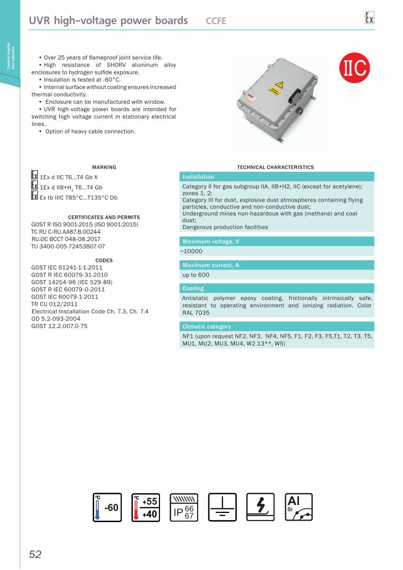
• Over 25 years of flameproof joint service life.• High resistance of SHORV aluminum alloy
enclosures to hydrogen sulfide exposure.• Insulation is tested at -60°C.• Internal surface without coating ensures increased
thermal conductivity. • Enclosure can be manufactured with window.• UVR high-voltage power boards are intended for
switching high voltage current in stationary electrical lines.
• Option of heavy cable connection.
MARKING
1Ex d IIС T6...T4 Gb X
1Ex d IIB+H2 T6...T4 Gb
Ex tb IIIC T85°С...T135°С Db
CERTIFICATES AND PERMITSGOST R ISO 9001-2015 (ISO 9001:2015)ТС RU С-RU.AA87.В.00244RU.OC BCCT 048-08.2017TU 3400-005-72453807-07
CODESGOST IEC 61241-1-1-2011GOST R IEC 60079-31-2010GOST 14254-96 (IEC 529-89)GOST R IEC 60079-0-2011GOST IEC 60079-1-2011TR CU 012/2011Electrical Installation Code Ch. 7.3, Ch. 7.4OD 5.2-093-2004GOST 12.2.007.0-75
TECHNICAL CHARACTERISTICS
Installation
Category II for gas subgroup IIA, IIB+H2, IIC (except for acetylene); zones 1, 2;Category III for dust, explosive dust atmospheres containing flying particles, conductive and non-conductive dust;Underground mines non-hazardous with gas (methane) and coal dust;Dangerous production facilities
Maximum voltage, V
~10000
Maximum current, A
up to 600
Coating
Antistatic polymer epoxy coating, frictionally intrinsically safe, resistant to operating environment and ionizing radiation. Color RAL 7035
Climatic category
NF1 (upon request NF2, NF3, NF4, NF5, F1, F2, F3, F5,T1, T2, T3, T5, MU1, MU2, MU3, MU4, W2.13**, W5)
IP 6667
53
UVR high-voltage power boards CCFE
Con
trol
boa
rds
and
cabi
nets
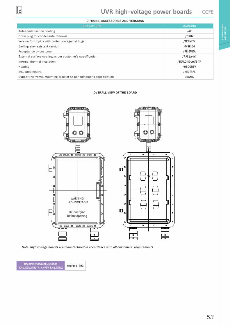
OPTIONS, ACCESSORIES AND VERSIONS
DESCRIPTION MARKING
Anti-condensation coating /AP
Drain plug for condensate removal /DKUV
Version for tropics with protection against bugs /TERMITY
Earthquake-resistant version /MSK-64
Acceptance by customer /PRIEMKA
External surface coating as per customer’s specification /RAL (code)
Internal thermal insulation /TEPLOISOLYATSIYA
Heating /OBOGREV
Insulated neutral /NEUTRAL
Supporting frame. Mounting bracket as per customer’s specification /RAMA
OVERALL VIEW OF THE BOARD
WARNING! HIGH VOLTAGE!
De-energize before opening
Note: high voltage boards are manufactured in accordance with all customers’ requirements.
Recommended cable glands KNV, KOV, KNVTN, KNVTV, KNE, KNVZ refer to p. 393
54
SHGV-AVR CCFE-R
Con
trol
boa
rds
and
cabi
nets
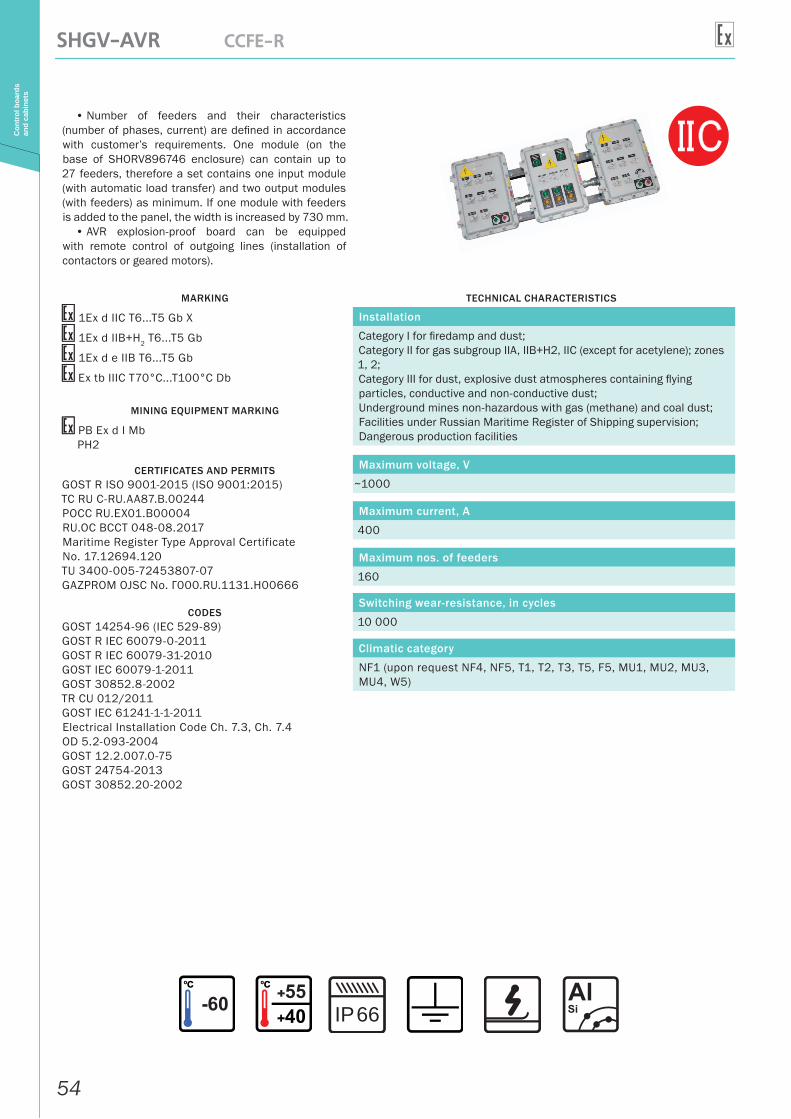
• Number of feeders and their characteristics (number of phases, current) are defined in accordance with customer’s requirements. One module (on the base of SHORV896746 enclosure) can contain up to 27 feeders, therefore a set contains one input module (with automatic load transfer) and two output modules (with feeders) as minimum. If one module with feeders is added to the panel, the width is increased by 730 mm.
• AVR explosion-proof board can be equipped with remote control of outgoing lines (installation of contactors or geared motors).
MARKING
1Ex d IIС T6...T5 Gb X
1Ex d IIB+H2 T6...T5 Gb
1Ex d e IIB T6...T5 Gb
Ex tb IIIC T70°С...T100°С Db
MINING EQUIPMENT MARKING
РВ Ex d I MbРН2
CERTIFICATES AND PERMITSGOST R ISO 9001-2015 (ISO 9001:2015)ТС RU С-RU.AA87.В.00244РОСС RU.EX01.B00004RU.OC BCCT 048-08.2017Maritime Register Type Approval Certificate No. 17.12694.120TU 3400-005-72453807-07GAZPROM OJSC No. Г000.RU.1131.H00666
CODESGOST 14254-96 (IEC 529-89)GOST R IEC 60079-0-2011GOST R IEC 60079-31-2010GOST IEC 60079-1-2011GOST 30852.8-2002TR CU 012/2011GOST IEC 61241-1-1-2011Electrical Installation Code Ch. 7.3, Ch. 7.4OD 5.2-093-2004GOST 12.2.007.0-75GOST 24754-2013GOST 30852.20-2002
TECHNICAL CHARACTERISTICS
Installation
Category I for firedamp and dust;Category II for gas subgroup IIA, IIB+H2, IIC (except for acetylene); zones 1, 2;Category III for dust, explosive dust atmospheres containing flying particles, conductive and non-conductive dust;Underground mines non-hazardous with gas (methane) and coal dust;Facilities under Russian Maritime Register of Shipping supervision;Dangerous production facilities
Maximum voltage, V
~1000
Maximum current, A
400
Maximum nos. of feeders
160
Switching wear-resistance, in cycles
10 000
Climatic category
NF1 (upon request NF4, NF5, T1, T2, T3, T5, F5, MU1, MU2, MU3, MU4, W5)
66IP
55
SHGV-AVR CCFE-R
Con
trol
boa
rds
and
cabi
nets
OPTIONS, ACCESSORIES AND VERSIONS
DESCRIPTION MARKING
Anti-condensation coating /AP
Drain plug for condensate removal /DKUV
Marine version /MORE
Version for tropics with protection against bugs /TERMITY
Earthquake-resistant version /MSK-64
Acceptance by customer /PRIEMKA
External surface coating as per customer’s specification /RAL (code)
Internal thermal insulation /TEPLOISOLYATSIYA
Heating /OBOGREV
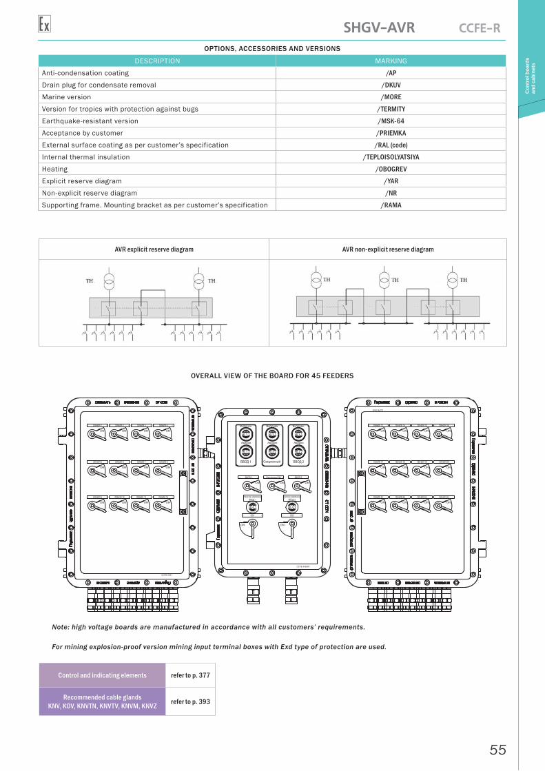
Explicit reserve diagram /YAR
Non-explicit reserve diagram /NR
Supporting frame. Mounting bracket as per customer’s specification /RAMA
AVR explicit reserve diagram AVR non-explicit reserve diagram
OVERALL VIEW OF THE BOARD FOR 45 FEEDERS
Note: high voltage boards are manufactured in accordance with all customers’ requirements.
For mining explosion-proof version mining input terminal boxes with Exd type of protection are used.
Control and indicating elements refer to p. 377
Recommended cable glands KNV, KOV, KNVTN, KNVTV, KNVM, KNVZ refer to p. 393
56
SHGV-IBP SA-BUFIP
Pow
er s
ourc
e,
stor
age
batte
ry
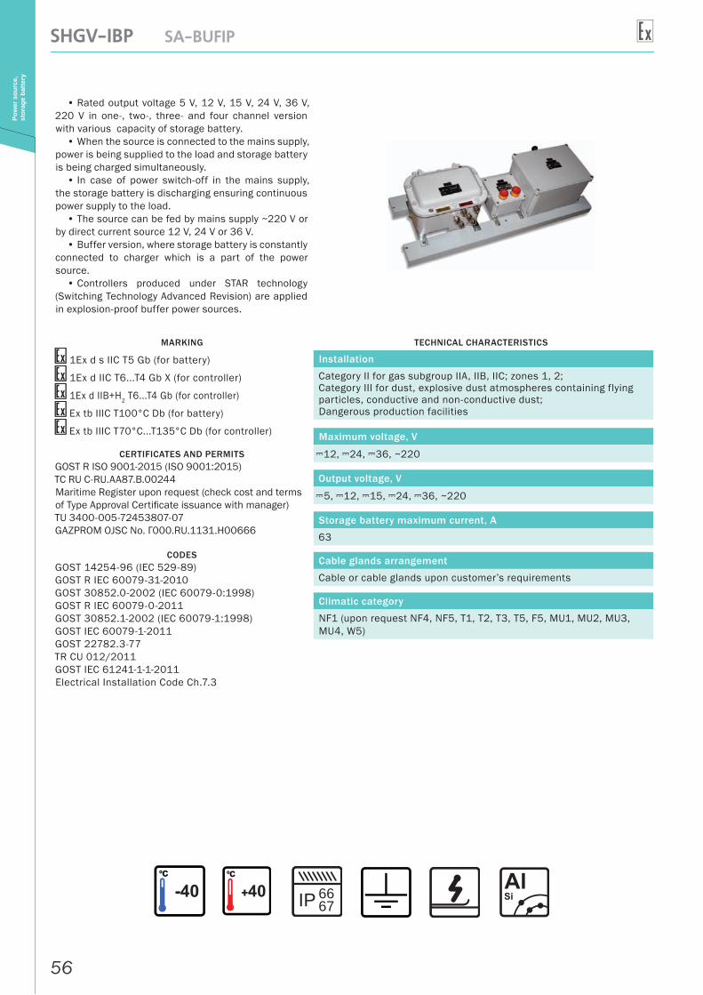
• Rated output voltage 5 V, 12 V, 15 V, 24 V, 36 V, 220 V in one-, two-, three- and four channel version with various capacity of storage battery.
• When the source is connected to the mains supply, power is being supplied to the load and storage battery is being charged simultaneously.
• In case of power switch-off in the mains supply, the storage battery is discharging ensuring continuous power supply to the load.
• The source can be fed by mains supply ~220 V or by direct current source 12 V, 24 V or 36 V.
• Buffer version, where storage battery is constantly connected to charger which is a part of the power source.
• Controllers produced under STAR technology (Switching Technology Advanced Revision) are applied in explosion-proof buffer power sources.
MARKING
1Ex d s IIC T5 Gb (for battery)
1Ex d IIC T6...T4 Gb Х (for controller)
1Ex d IIB+H2 T6...T4 Gb (for controller)
Ex tb IIIC T100°С Db (for battery)
Ex tb IIIC T70°С...T135°С Db (for controller)
CERTIFICATES AND PERMITSGOST R ISO 9001-2015 (ISO 9001:2015)ТС RU С-RU.AA87.В.00244Maritime Register upon request (check cost and terms of Type Approval Certificate issuance with manager)TU 3400-005-72453807-07GAZPROM OJSC No. Г000.RU.1131.H00666
CODESGOST 14254-96 (IEC 529-89)GOST R IEC 60079-31-2010GOST 30852.0-2002 (IEC 60079-0:1998)GOST R IEC 60079-0-2011GOST 30852.1-2002 (IEC 60079-1:1998)GOST IЕС 60079-1-2011GOST 22782.3-77TR CU 012/2011GOST IEC 61241-1-1-2011Electrical Installation Code Ch.7.3
TECHNICAL CHARACTERISTICS
Installation
Category II for gas subgroup IIA, IIB, IIC; zones 1, 2;Category III for dust, explosive dust atmospheres containing flying particles, conductive and non-conductive dust;Dangerous production facilities
Maximum voltage, V
A12, A24, A36, ~220
Output voltage, V
A5, A12, A15, A24, A36, ~220
Storage battery maximum current, A
63
Cable glands arrangement
Cable or cable glands upon customer’s requirements
Climatic category
NF1 (upon request NF4, NF5, T1, T2, T3, T5, F5, MU1, MU2, MU3, MU4, W5)
IP 6667
57
SHGV-IBP SA-BUFIP
Pow
er s
ourc
e,
stor
age
batte
ry
OPTIONS, ACCESSORIES AND VERSIONS
DESCRIPTION MARKING
Version for tropics with protection against bugs /TERMITY
Earthquake-resistant version /MSK-64
Acceptance by customer /PRIEMKA
External surface coating as per customer’s specification /RAL (code)
Internal thermal insulation /TEPLOISOLYATSIYA
Heating /OBOGREV
Supporting frame. Mounting bracket as per customer’s specification /RAMA
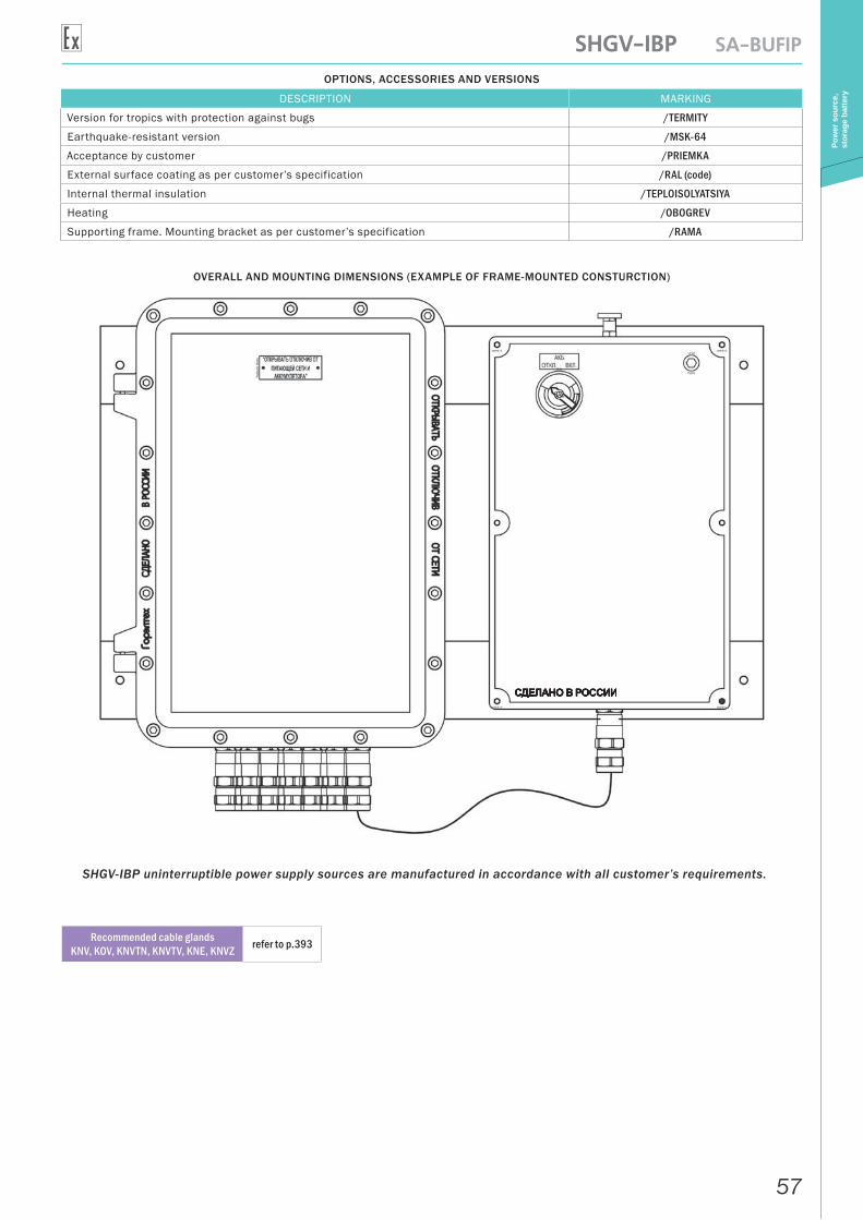
OVERALL AND MOUNTING DIMENSIONS (EXAMPLE OF FRAME-MOUNTED CONSTURCTION)
SHGV-IBP uninterruptible power supply sources are manufactured in accordance with all customer’s requirements.
Recommended cable glands KNV, KOV, KNVTN, KNVTV, KNE, KNVZ refer to p.393

58
VIP-AKB SA-BATT
Pow
er s
ourc
e,
stor
age
batte
ry
• The battery is equipped with short circuit protection device and a button for power supply circuit release, which allows to carry out installation or replacement in hazardous area.
• In case of completing with lead acid system (SLA), the battery is equipped with fire-stopping system of removal of gazes which are produced in the process of operation of the battery, and allows to sustain hydrogen concentration at level lower that 2%.
• In case of completing with lead acid system (SLA), VIP-AKB batteries can be equipped with electrical heating connected to external power source.
MARKING
1Ex d s IIC T5 Gb
Ex tb IIIC T100°С Db
CERTIFICATES AND PERMITSGOST R ISO 9001-2015 (ISO 9001:2015)ТС RU С-RU.AA87.В.00244Maritime Register upon request (check cost and terms of Type Approval Certificate issuance with manager)TU 3400-005-72453807-07GAZPROM OJSC No. Г000.RU.1131.H00666
CODESGOST 14254-96 (IEC 529-89)GOST R IEC 60079-31-2010GOST 30852.0-2002 (IEC 60079-0:1998)GOST 30852.1-2002 (IEC 60079-1:1998)TR CU 012/2011GOST 22782.3-77,GOST IEC 61241-1-1-2011Electrical Installation Code Ch. 7.3, Ch. 7.4
TECHNICAL CHARACTERISTICS
Installation
Category II for gas subgroup IIA, IIB, IIC; zones 1, 2;Category III for dust, explosive dust atmospheres containing flying particles, conductive and non-conductive dust;Dangerous production facilities
Storage battery voltage, V
A6, A12, A24, A36, A48 (other voltage upon approval)
Storage battery maximum current, A
63
Cable glands arrangement
Cable or cable glands upon customer’s requirements
Enclosure mounting
4 external mounting points
Climatic category
NF1 (upon request NF4, NF5, T1, T2, T3, T5, F5, MU1, MU2, MU3, MU4, W5)
IP 6667
59
VIP-AKB SA-BATT
Pow
er s
ourc
e,
stor
age
batte
ryOPTIONS, ACCESSORIES AND VERSIONS
DESCRIPTION MARKING
Version for tropics with protection against bugs /TERMITY
Acceptance by customer /PRIEMKA
External surface coating as per customer’s specification /RAL (code)
Internal thermal insulation /TEPLOISOLYATSIYA
Heating /OBOGREV
Supporting frame. Mounting bracket as per customer’s specification /RAMA
Mounting rail /REIKA
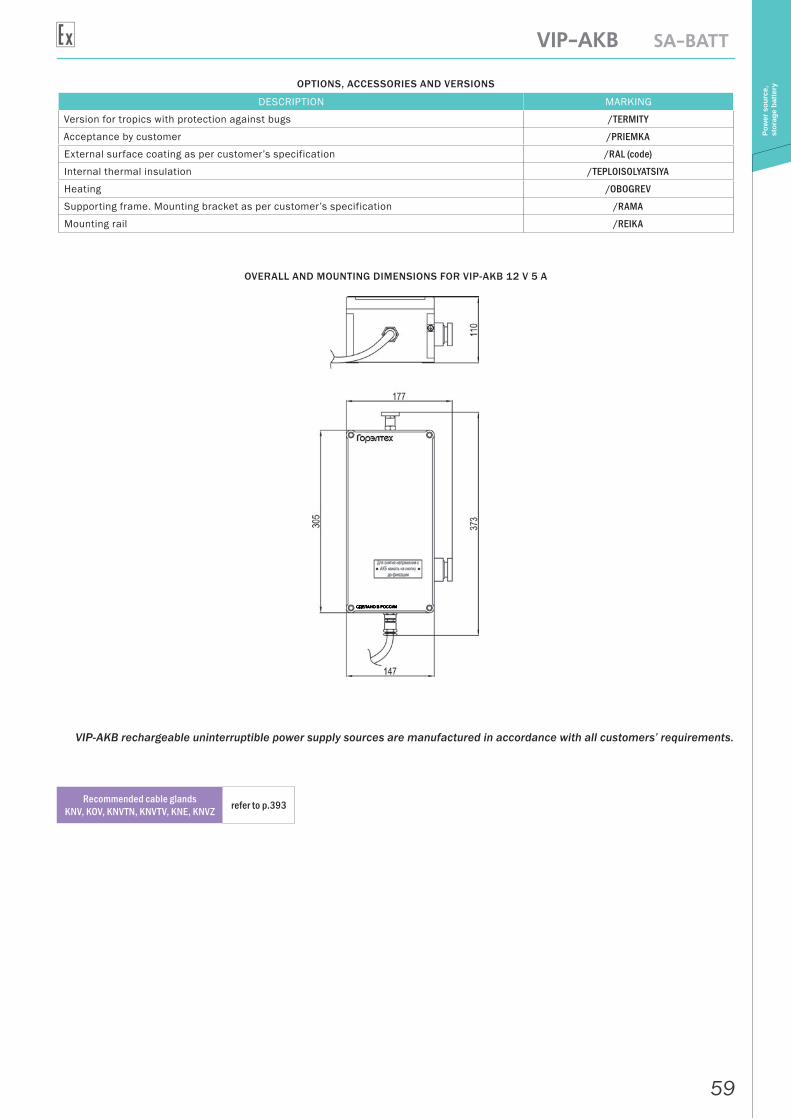
OVERALL AND MOUNTING DIMENSIONS FOR VIP-AKB 12 V 5 A
VIP-AKB rechargeable uninterruptible power supply sources are manufactured in accordance with all customers’ requirements.
Recommended cable glands KNV, KOV, KNVTN, KNVTV, KNE, KNVZ refer to p.393
60
VIP-AIP CS-EXPL/X-AVTOIP
Pow
er s
ourc
e,
stor
age
batte
ry
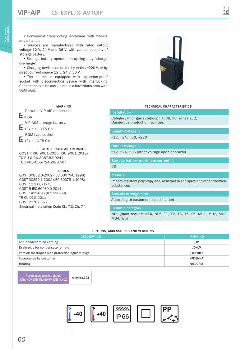
• Convenient transporting enclosure with wheels and a handle.
• Sources are manufactured with rated output voltage 12 V, 24 V and 36 V, with various capacity of storage battery.
• Storage battery operates in cycling duty “charge-discharge”.
• Charging device can be fed by mains ~220 V, or by direct current source 12 V, 24 V, 36 V.
• The source is equipped with explosion-proof socket with disconnecting device with interlocking. Connection can be carried out in a hazardous area with VGM plug.
MARKINGPortable VIP-AIP enclosure:
II GbVIP-AKB storage battery:
1Ex d s IIC T5 GbRGM type socket:
1Ex d IIC T5 Gb
CERTIFICATES AND PERMITSGOST R ISO 9001-2015 (ISO 9001:2015)ТС RU С-RU.AA87.В.00244TU 3400-005-72453807-07
CODESGOST 30852.0-2002 (IEC 60079-0:1998)GOST 30852.1-2002 (IEC 60079-1:1998)GOST 12.2.007.0-75GOST R IEC 60079-0-2011GOST 14254-96 (IEC 529-89)TR CU 012/2011GOST 22782.3-77Electrical Installation Code Ch. 7.3, Ch. 7.4
TECHNICAL CHARACTERISTICS
Installation
Category II for gas subgroup IIA, IIB, IIC; zones 1, 2;Dangerous production facilities
Supply voltage, V
A12, A24, A36, ~220
Output voltage, V
A12, A24, A36 (other voltage upon approval)
Storage battery maximum current, A
63
Material
Impact-resistant polypropylene, resistant to salt spray and other chemical substances
Sockets arrangement
According to customer’s specification
Climatic category
NF1 (upon request NF4, NF5, T1, T2, T3, T5, F5, MU1, MU2, MU3, MU4, W5)
OPTIONS, ACCESSORIES AND VERSIONS
DESCRIPTION MARKING
Anti-condensation coating /AP
Drain plug for condensate removal /DKUV
Version for tropics with protection against bugs /TERMITY
Acceptance by customer /PRIEMKA
Heating /OBOGREV
Recommended cable glands KNV, KOV, KNVTN, KNVTV, KNE, KNVZ refer to p.393
66IP
61
SHVG-PUSK CCFE-X-PUSK
Star
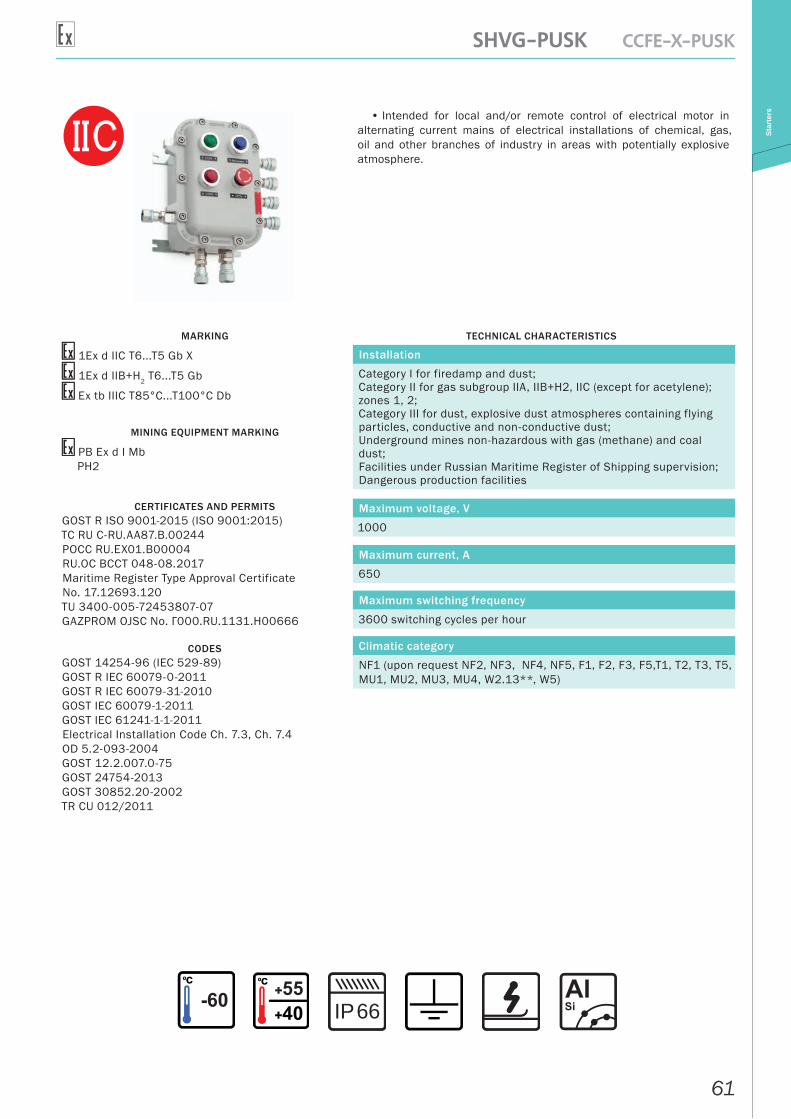
ters• Intended for local and/or remote control of electrical motor in
alternating current mains of electrical installations of chemical, gas, oil and other branches of industry in areas with potentially explosive atmosphere.
MARKING
1Ex d IIС T6...T5 Gb X
1Ex d IIB+H2 T6...T5 Gb
Ex tb IIIC T85°С...T100°С Db
MINING EQUIPMENT MARKING
РВ Ex d I MbРН2
CERTIFICATES AND PERMITSGOST R ISO 9001-2015 (ISO 9001:2015)ТС RU С-RU.AA87.В.00244РОСС RU.EX01.B00004RU.OC BCCT 048-08.2017Maritime Register Type Approval Certificate No. 17.12693.120TU 3400-005-72453807-07GAZPROM OJSC No. Г000.RU.1131.H00666
CODESGOST 14254-96 (IEC 529-89)GOST R IEC 60079-0-2011GOST R IEC 60079-31-2010GOST IEC 60079-1-2011GOST IEC 61241-1-1-2011Electrical Installation Code Ch. 7.3, Ch. 7.4OD 5.2-093-2004GOST 12.2.007.0-75GOST 24754-2013GOST 30852.20-2002TR CU 012/2011
TECHNICAL CHARACTERISTICS
Installation
Category I for firedamp and dust;Category II for gas subgroup IIA, IIB+H2, IIC (except for acetylene); zones 1, 2;Category III for dust, explosive dust atmospheres containing flying particles, conductive and non-conductive dust;Underground mines non-hazardous with gas (methane) and coal dust;Facilities under Russian Maritime Register of Shipping supervision;Dangerous production facilities
Maximum voltage, V
1000
Maximum current, A
650
Maximum switching frequency
3600 switching cycles per hour
Climatic category
NF1 (upon request NF2, NF3, NF4, NF5, F1, F2, F3, F5,T1, T2, T3, T5, MU1, MU2, MU3, MU4, W2.13**, W5)
66IP
62
SHVG-PUSK CCFE-X-PUSKSt
arte
rs
OPTIONS, ACCESSORIES AND VERSIONS
DESCRIPTION MARKING
Anti-condensation coating /AP
Drain plug for condensate removal /DKUV
Marine version /MORE
Version for tropics with protection against bugs /TERMITY
Earthquake-resistant version /MSK-64
Acceptance by customer /PRIEMKA
External surface coating as per customer’s specification /RAL (code)
Material of enclosure – highly corrosion-resistant stainless chrome-nickel casting steel /N
Internal thermal insulation /TEPLOISOLYATSIYA
Heating /OBOGREV
Soft start /PP
Remote control and local network control /MLS
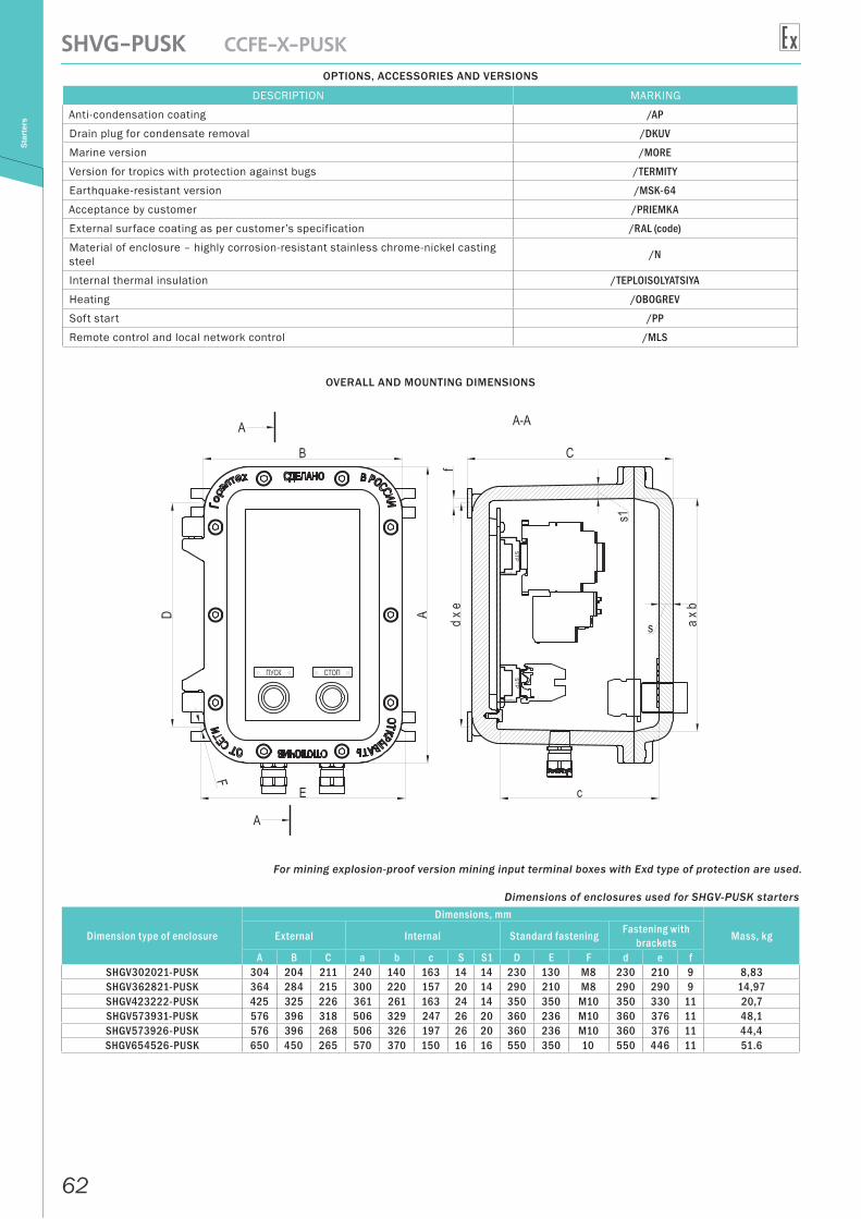
OVERALL AND MOUNTING DIMENSIONS
For mining explosion-proof version mining input terminal boxes with Exd type of protection are used.
Dimensions of enclosures used for SHGV-PUSK starters
Dimension type of enclosure
Dimensions, mm
Mass, kgExternal Internal Standard fastening Fastening with brackets
A B C a b c S S1 D E F d e fSHGV302021-PUSK 304 204 211 240 140 163 14 14 230 130 М8 230 210 9 8,83SHGV362821-PUSK 364 284 215 300 220 157 20 14 290 210 М8 290 290 9 14,97SHGV423222-PUSK 425 325 226 361 261 163 24 14 350 350 M10 350 330 11 20,7SHGV573931-PUSK 576 396 318 506 329 247 26 20 360 236 М10 360 376 11 48,1SHGV573926-PUSK 576 396 268 506 326 197 26 20 360 236 М10 360 376 11 44,4SHGV654526-PUSK 650 450 265 570 370 150 16 16 550 350 10 550 446 11 51.6
63
SHVG-PUSK CCFE-X-PUSK
Star
ters
Correspondence of explosion-proof starters of different manufacturers*
UUKV-32 (without thermal relay) SHGV302021-PUSK-M-2-220-2KOV1(V) Explosion-proof starter 32 A without thermal relay, local control, 2 KOV1 cable glands for armored cable, diameter of crimped cable 9-17 mm
UUKV-32 (with thermal relay) SHGV362821-PUSK-M-32 Т-220-32-2KOV1(V) Explosion-proof starter 32 A with thermal relay, local control, 2 KOV1 cable glands for armored cable, diameter of crimped cable 9-17 mm
UUKV-32P (reversing without thermal relay) SHGV302021-PUSK-M-32 Р-220-2KOV1(V)
Explosion-proof starter 32 A without thermal relay, reversing, local control, 2 KOV1 cable glands for armored cable, diameter of crimped cable 9-17 mm
UUKV-32P (reversing with thermal relay) SHGV362821-PUSK-M-32 R Т-220-32-2KOV1(V)
Explosion-proof starter 32 A with thermal relay, reversing, local control, 2 KOV1 cable glands for armored cable, diameter of crimped cable 9-17 mm
*You can use the following order form: SHGV-PUSK starter which corresponds to UUKV-32 (without thermal relay)
FORMATION OF MARKING
SHGV-X-PUSK-D-X P T-X-X-X X(A)/X – TU 3400-005-72453807-07
Product nameSize of the enclosure (6 digits)Remote control (if applicable)Rated current, AReversing (if applicable)Thermal relay (if applicable)Rated voltage of coil, VThermal relay setting current, AQuantity of cable glandsType of cable glandsSide of cable glands locationOptions, accessories and versions
Example of order: SHGV302021-PUSK-9Т-220-8-2KOV1(D) – TU 3400-005-72453807-07 Starter on the base of SHORV302021 enclosure, completed with:
-- 1 contactor 9 A-- 1 thermal relay with setting current 8 A-- coil, voltage 220 V-- 2 buttons (Start, Stop) for local control-- 2 KOV1 type cable glands for armored cable
If you find it difficult to select enclosure size in accordance with required characteristics, just leave Xs instead of digits after box name (SHGV-X-PUSK).
Table of names matching
Previous international name “ZAVOD GORELTEX” Co. Ltd.TU 3400-005-72453807-07
The Customs Union name “ZAVOD GORELTEX” Co. Ltd.TU 3400-005-72453807-07
CCFE-X-PUSK SHGV -...-PUSKCCFE-1P-PUSK SHGV302021-PUSK
CCFE-3BP-PUSK SHGV362821-PUSKCCFE-4BP-PUSK SHGV423222-PUSKCCFE-45-PUSK SHGV573931-PUSK
CCFE-45B-PUSK SHGV573926-PUSKCCFE-5B-PUSK SHGV654526-PUSK
Control and indicating elements refer to p.377
Recommended cable glands KNV, KOV, KNV-TN, KNV-TV, KNV-M, KNV-Z refer to p.393
64
SHVG-PUSK CCFE-X-PUSKSt
arte
rs
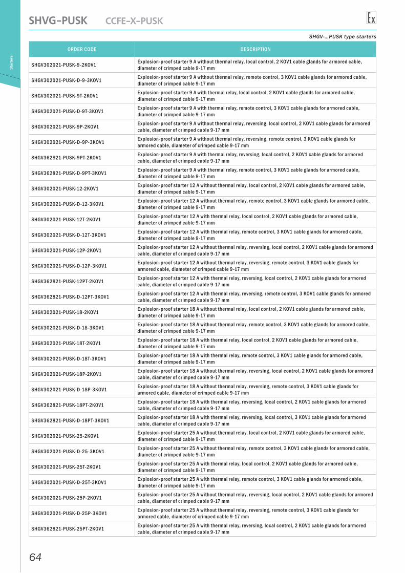
SHGV-…PUSK type starters
ORDER CODE DESCRIPTION
SHGV302021-PUSK-9-2KOV1 Explosion-proof starter 9 A without thermal relay, local control, 2 KOV1 cable glands for armored cable, diameter of crimped cable 9-17 mm
SHGV302021-PUSK-D-9-3KOV1 Explosion-proof starter 9 A without thermal relay, remote control, 3 KOV1 cable glands for armored cable, diameter of crimped cable 9-17 mm
SHGV302021-PUSK-9Т-2KOV1 Explosion-proof starter 9 A with thermal relay, local control, 2 KOV1 cable glands for armored cable, diameter of crimped cable 9-17 mm
SHGV302021-PUSK-D-9Т-3KOV1 Explosion-proof starter 9 A with thermal relay, remote control, 3 KOV1 cable glands for armored cable, diameter of crimped cable 9-17 mm
SHGV302021-PUSK-9Р-2KOV1 Explosion-proof starter 9 A without thermal relay, reversing, local control, 2 KOV1 cable glands for armored cable, diameter of crimped cable 9-17 mm
SHGV302021-PUSK-D-9Р-3KOV1 Explosion-proof starter 9 A without thermal relay, reversing, remote control, 3 KOV1 cable glands for armored cable, diameter of crimped cable 9-17 mm
SHGV362821-PUSK-9РТ-2KOV1 Explosion-proof starter 9 A with thermal relay, reversing, local control, 2 KOV1 cable glands for armored cable, diameter of crimped cable 9-17 mm
SHGV362821-PUSK-D-9РТ-3KOV1 Explosion-proof starter 9 A with thermal relay, remote control, 3 KOV1 cable glands for armored cable, diameter of crimped cable 9-17 mm
SHGV302021-PUSK-12-2KOV1 Explosion-proof starter 12 A without thermal relay, local control, 2 KOV1 cable glands for armored cable, diameter of crimped cable 9-17 mm
SHGV302021-PUSK-D-12-3KOV1 Explosion-proof starter 12 A without thermal relay, remote control, 3 KOV1 cable glands for armored cable, diameter of crimped cable 9-17 mm
SHGV302021-PUSK-12Т-2KOV1 Explosion-proof starter 12 A with thermal relay, local control, 2 KOV1 cable glands for armored cable, diameter of crimped cable 9-17 mm
SHGV302021-PUSK-D-12Т-3KOV1 Explosion-proof starter 12 A with thermal relay, remote control, 3 KOV1 cable glands for armored cable, diameter of crimped cable 9-17 mm
SHGV302021-PUSK-12Р-2KOV1 Explosion-proof starter 12 A without thermal relay, reversing, local control, 2 KOV1 cable glands for armored cable, diameter of crimped cable 9-17 mm
SHGV302021-PUSK-D-12Р-3KOV1 Explosion-proof starter 12 A without thermal relay, reversing, remote control, 3 KOV1 cable glands for armored cable, diameter of crimped cable 9-17 mm
SHGV362821-PUSK-12РТ-2KOV1 Explosion-proof starter 12 A with thermal relay, reversing, local control, 2 KOV1 cable glands for armored cable, diameter of crimped cable 9-17 mm
SHGV362821-PUSK-D-12РТ-3KOV1 Explosion-proof starter 12 A with thermal relay, reversing, remote control, 3 KOV1 cable glands for armored cable, diameter of crimped cable 9-17 mm
SHGV302021-PUSK-18-2KOV1 Explosion-proof starter 18 A without thermal relay, local control, 2 KOV1 cable glands for armored cable, diameter of crimped cable 9-17 mm
SHGV302021-PUSK-D-18-3KOV1 Explosion-proof starter 18 A without thermal relay, remote control, 3 KOV1 cable glands for armored cable, diameter of crimped cable 9-17 mm
SHGV302021-PUSK-18Т-2KOV1 Explosion-proof starter 18 A with thermal relay, local control, 2 KOV1 cable glands for armored cable, diameter of crimped cable 9-17 mm
SHGV302021-PUSK-D-18Т-3KOV1 Explosion-proof starter 18 A with thermal relay, remote control, 3 KOV1 cable glands for armored cable, diameter of crimped cable 9-17 mm
SHGV302021-PUSK-18Р-2KOV1 Explosion-proof starter 18 A without thermal relay, reversing, local control, 2 KOV1 cable glands for armored cable, diameter of crimped cable 9-17 mm
SHGV302021-PUSK-D-18Р-3KOV1 Explosion-proof starter 18 A without thermal relay, reversing, remote control, 3 KOV1 cable glands for armored cable, diameter of crimped cable 9-17 mm
SHGV362821-PUSK-18РТ-2KOV1 Explosion-proof starter 18 A with thermal relay, reversing, local control, 2 KOV1 cable glands for armored cable, diameter of crimped cable 9-17 mm
SHGV362821-PUSK-D-18РТ-3KOV1 Explosion-proof starter 18 A with thermal relay, reversing, local control, 3 KOV1 cable glands for armored cable, diameter of crimped cable 9-17 mm
SHGV302021-PUSK-25-2KOV1 Explosion-proof starter 25 A without thermal relay, local control, 2 KOV1 cable glands for armored cable, diameter of crimped cable 9-17 mm
SHGV302021-PUSK-D-25-3KOV1 Explosion-proof starter 25 A without thermal relay, remote control, 3 KOV1 cable glands for armored cable, diameter of crimped cable 9-17 mm
SHGV302021-PUSK-25Т-2KOV1 Explosion-proof starter 25 A with thermal relay, local control, 2 KOV1 cable glands for armored cable, diameter of crimped cable 9-17 mm
SHGV302021-PUSK-D-25Т-3KOV1 Explosion-proof starter 25 A with thermal relay, remote control, 3 KOV1 cable glands for armored cable, diameter of crimped cable 9-17 mm
SHGV302021-PUSK-25Р-2KOV1 Explosion-proof starter 25 A without thermal relay, reversing, local control, 2 KOV1 cable glands for armored cable, diameter of crimped cable 9-17 mm
SHGV302021-PUSK-D-25Р-3KOV1 Explosion-proof starter 25 A without thermal relay, reversing, remote control, 3 KOV1 cable glands for armored cable, diameter of crimped cable 9-17 mm
SHGV362821-PUSK-25РТ-2KOV1 Explosion-proof starter 25 A with thermal relay, reversing, local control, 2 KOV1 cable glands for armored cable, diameter of crimped cable 9-17 mm
65
SHVG-PUSK CCFE-X-PUSK
Star
ters
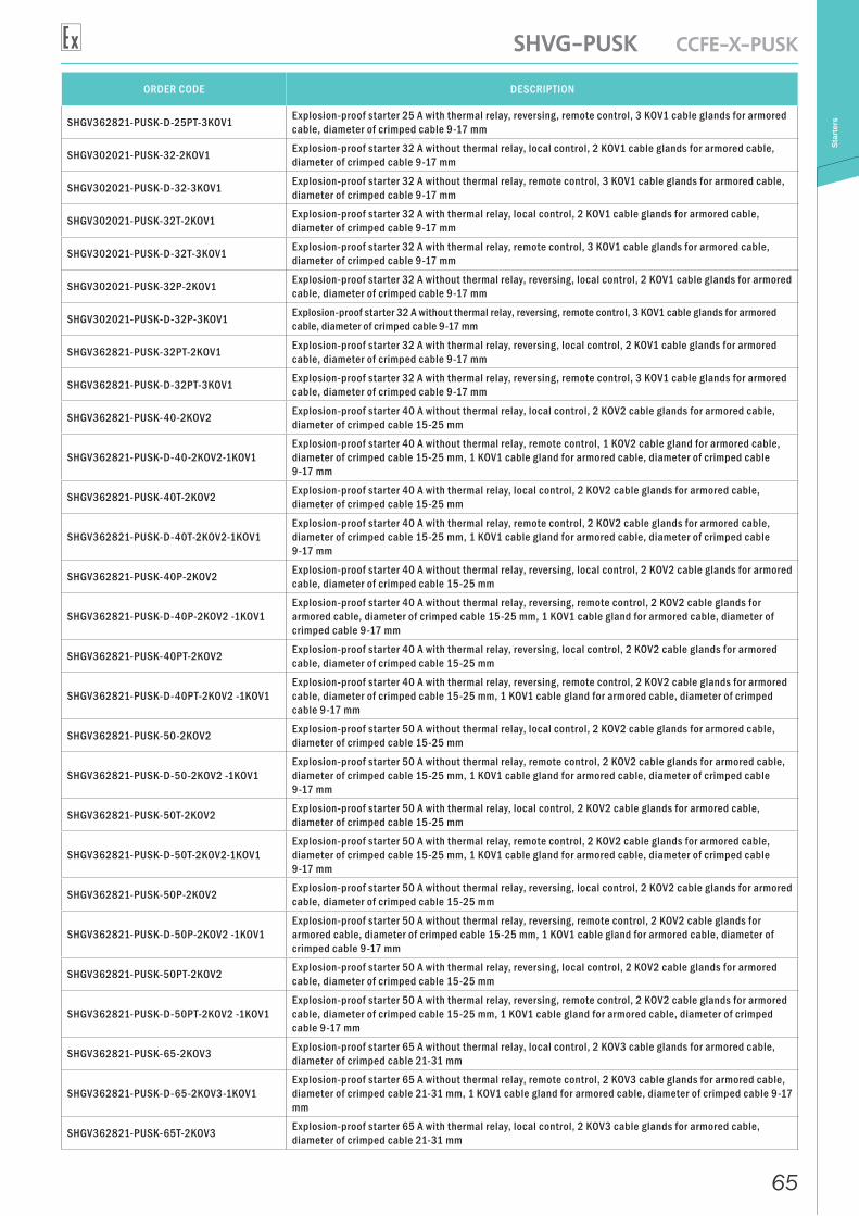
ORDER CODE DESCRIPTION
SHGV362821-PUSK-D-25РТ-3KOV1 Explosion-proof starter 25 A with thermal relay, reversing, remote control, 3 KOV1 cable glands for armored cable, diameter of crimped cable 9-17 mm
SHGV302021-PUSK-32-2KOV1 Explosion-proof starter 32 A without thermal relay, local control, 2 KOV1 cable glands for armored cable, diameter of crimped cable 9-17 mm
SHGV302021-PUSK-D-32-3KOV1 Explosion-proof starter 32 A without thermal relay, remote control, 3 KOV1 cable glands for armored cable, diameter of crimped cable 9-17 mm
SHGV302021-PUSK-32Т-2KOV1 Explosion-proof starter 32 A with thermal relay, local control, 2 KOV1 cable glands for armored cable, diameter of crimped cable 9-17 mm
SHGV302021-PUSK-D-32Т-3KOV1 Explosion-proof starter 32 A with thermal relay, remote control, 3 KOV1 cable glands for armored cable, diameter of crimped cable 9-17 mm
SHGV302021-PUSK-32Р-2KOV1 Explosion-proof starter 32 A without thermal relay, reversing, local control, 2 KOV1 cable glands for armored cable, diameter of crimped cable 9-17 mm
SHGV302021-PUSK-D-32Р-3KOV1 Explosion-proof starter 32 A without thermal relay, reversing, remote control, 3 KOV1 cable glands for armored cable, diameter of crimped cable 9-17 mm
SHGV362821-PUSK-32РТ-2KOV1 Explosion-proof starter 32 A with thermal relay, reversing, local control, 2 KOV1 cable glands for armored cable, diameter of crimped cable 9-17 mm
SHGV362821-PUSK-D-32РТ-3KOV1 Explosion-proof starter 32 A with thermal relay, reversing, remote control, 3 KOV1 cable glands for armored cable, diameter of crimped cable 9-17 mm
SHGV362821-PUSK-40-2KOV2 Explosion-proof starter 40 A without thermal relay, local control, 2 KOV2 cable glands for armored cable, diameter of crimped cable 15-25 mm
SHGV362821-PUSK-D-40-2KOV2-1KOV1Explosion-proof starter 40 A without thermal relay, remote control, 1 KOV2 cable gland for armored cable, diameter of crimped cable 15-25 mm, 1 KOV1 cable gland for armored cable, diameter of crimped cable 9-17 mm
SHGV362821-PUSK-40Т-2KOV2 Explosion-proof starter 40 A with thermal relay, local control, 2 KOV2 cable glands for armored cable, diameter of crimped cable 15-25 mm
SHGV362821-PUSK-D-40Т-2KOV2-1KOV1Explosion-proof starter 40 A with thermal relay, remote control, 2 KOV2 cable glands for armored cable, diameter of crimped cable 15-25 mm, 1 KOV1 cable gland for armored cable, diameter of crimped cable 9-17 mm
SHGV362821-PUSK-40Р-2KOV2 Explosion-proof starter 40 A without thermal relay, reversing, local control, 2 KOV2 cable glands for armored cable, diameter of crimped cable 15-25 mm
SHGV362821-PUSK-D-40Р-2KOV2 -1KOV1Explosion-proof starter 40 A without thermal relay, reversing, remote control, 2 KOV2 cable glands for armored cable, diameter of crimped cable 15-25 mm, 1 KOV1 cable gland for armored cable, diameter of crimped cable 9-17 mm
SHGV362821-PUSK-40РТ-2KOV2 Explosion-proof starter 40 A with thermal relay, reversing, local control, 2 KOV2 cable glands for armored cable, diameter of crimped cable 15-25 mm
SHGV362821-PUSK-D-40РТ-2KOV2 -1KOV1Explosion-proof starter 40 A with thermal relay, reversing, remote control, 2 KOV2 cable glands for armored cable, diameter of crimped cable 15-25 mm, 1 KOV1 cable gland for armored cable, diameter of crimped cable 9-17 mm
SHGV362821-PUSK-50-2KOV2 Explosion-proof starter 50 A without thermal relay, local control, 2 KOV2 cable glands for armored cable, diameter of crimped cable 15-25 mm
SHGV362821-PUSK-D-50-2KOV2 -1KOV1Explosion-proof starter 50 A without thermal relay, remote control, 2 KOV2 cable glands for armored cable, diameter of crimped cable 15-25 mm, 1 KOV1 cable gland for armored cable, diameter of crimped cable 9-17 mm
SHGV362821-PUSK-50Т-2KOV2 Explosion-proof starter 50 A with thermal relay, local control, 2 KOV2 cable glands for armored cable, diameter of crimped cable 15-25 mm
SHGV362821-PUSK-D-50Т-2KOV2-1KOV1Explosion-proof starter 50 A with thermal relay, remote control, 2 KOV2 cable glands for armored cable, diameter of crimped cable 15-25 mm, 1 KOV1 cable gland for armored cable, diameter of crimped cable 9-17 mm
SHGV362821-PUSK-50Р-2KOV2 Explosion-proof starter 50 A without thermal relay, reversing, local control, 2 KOV2 cable glands for armored cable, diameter of crimped cable 15-25 mm
SHGV362821-PUSK-D-50Р-2KOV2 -1KOV1Explosion-proof starter 50 A without thermal relay, reversing, remote control, 2 KOV2 cable glands for armored cable, diameter of crimped cable 15-25 mm, 1 KOV1 cable gland for armored cable, diameter of crimped cable 9-17 mm
SHGV362821-PUSK-50РТ-2KOV2 Explosion-proof starter 50 A with thermal relay, reversing, local control, 2 KOV2 cable glands for armored cable, diameter of crimped cable 15-25 mm
SHGV362821-PUSK-D-50РТ-2KOV2 -1KOV1Explosion-proof starter 50 A with thermal relay, reversing, remote control, 2 KOV2 cable glands for armored cable, diameter of crimped cable 15-25 mm, 1 KOV1 cable gland for armored cable, diameter of crimped cable 9-17 mm
SHGV362821-PUSK-65-2KOV3 Explosion-proof starter 65 A without thermal relay, local control, 2 KOV3 cable glands for armored cable, diameter of crimped cable 21-31 mm
SHGV362821-PUSK-D-65-2KOV3-1KOV1Explosion-proof starter 65 A without thermal relay, remote control, 2 KOV3 cable glands for armored cable, diameter of crimped cable 21-31 mm, 1 KOV1 cable gland for armored cable, diameter of crimped cable 9-17 mm
SHGV362821-PUSK-65Т-2KOV3 Explosion-proof starter 65 A with thermal relay, local control, 2 KOV3 cable glands for armored cable, diameter of crimped cable 21-31 mm
66
SHVG-PUSK CCFE-X-PUSKSt
arte
rs
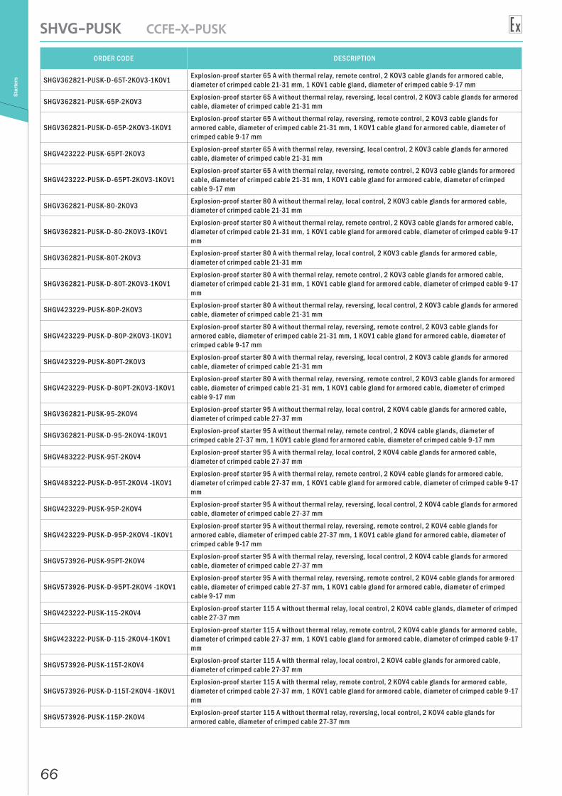
ORDER CODE DESCRIPTION
SHGV362821-PUSK-D-65Т-2KOV3-1KOV1 Explosion-proof starter 65 A with thermal relay, remote control, 2 KOV3 cable glands for armored cable, diameter of crimped cable 21-31 mm, 1 KOV1 cable gland, diameter of crimped cable 9-17 mm
SHGV362821-PUSK-65Р-2KOV3 Explosion-proof starter 65 A without thermal relay, reversing, local control, 2 KOV3 cable glands for armored cable, diameter of crimped cable 21-31 mm
SHGV362821-PUSK-D-65Р-2KOV3-1KOV1Explosion-proof starter 65 A without thermal relay, reversing, remote control, 2 KOV3 cable glands for armored cable, diameter of crimped cable 21-31 mm, 1 KOV1 cable gland for armored cable, diameter of crimped cable 9-17 mm
SHGV423222-PUSK-65РТ-2KOV3 Explosion-proof starter 65 A with thermal relay, reversing, local control, 2 KOV3 cable glands for armored cable, diameter of crimped cable 21-31 mm
SHGV423222-PUSK-D-65РТ-2KOV3-1KOV1Explosion-proof starter 65 A with thermal relay, reversing, remote control, 2 KOV3 cable glands for armored cable, diameter of crimped cable 21-31 mm, 1 KOV1 cable gland for armored cable, diameter of crimped cable 9-17 mm
SHGV362821-PUSK-80-2KOV3 Explosion-proof starter 80 A without thermal relay, local control, 2 KOV3 cable glands for armored cable, diameter of crimped cable 21-31 mm
SHGV362821-PUSK-D-80-2KOV3-1KOV1Explosion-proof starter 80 A without thermal relay, remote control, 2 KOV3 cable glands for armored cable, diameter of crimped cable 21-31 mm, 1 KOV1 cable gland for armored cable, diameter of crimped cable 9-17 mm
SHGV362821-PUSK-80Т-2KOV3 Explosion-proof starter 80 A with thermal relay, local control, 2 KOV3 cable glands for armored cable, diameter of crimped cable 21-31 mm
SHGV362821-PUSK-D-80Т-2KOV3-1KOV1Explosion-proof starter 80 A with thermal relay, remote control, 2 KOV3 cable glands for armored cable, diameter of crimped cable 21-31 mm, 1 KOV1 cable gland for armored cable, diameter of crimped cable 9-17 mm
SHGV423229-PUSK-80Р-2KOV3 Explosion-proof starter 80 A without thermal relay, reversing, local control, 2 KOV3 cable glands for armored cable, diameter of crimped cable 21-31 mm
SHGV423229-PUSK-D-80Р-2KOV3-1KOV1Explosion-proof starter 80 A without thermal relay, reversing, remote control, 2 KOV3 cable glands for armored cable, diameter of crimped cable 21-31 mm, 1 KOV1 cable gland for armored cable, diameter of crimped cable 9-17 mm
SHGV423229-PUSK-80РТ-2KOV3 Explosion-proof starter 80 A with thermal relay, reversing, local control, 2 KOV3 cable glands for armored cable, diameter of crimped cable 21-31 mm
SHGV423229-PUSK-D-80РТ-2KOV3-1KOV1Explosion-proof starter 80 A with thermal relay, reversing, remote control, 2 KOV3 cable glands for armored cable, diameter of crimped cable 21-31 mm, 1 KOV1 cable gland for armored cable, diameter of crimped cable 9-17 mm
SHGV362821-PUSK-95-2KOV4 Explosion-proof starter 95 A without thermal relay, local control, 2 KOV4 cable glands for armored cable, diameter of crimped cable 27-37 mm
SHGV362821-PUSK-D-95-2KOV4-1KOV1 Explosion-proof starter 95 A without thermal relay, remote control, 2 KOV4 cable glands, diameter of crimped cable 27-37 mm, 1 KOV1 cable gland for armored cable, diameter of crimped cable 9-17 mm
SHGV483222-PUSK-95Т-2KOV4 Explosion-proof starter 95 A with thermal relay, local control, 2 KOV4 cable glands for armored cable, diameter of crimped cable 27-37 mm
SHGV483222-PUSK-D-95Т-2KOV4 -1KOV1Explosion-proof starter 95 A with thermal relay, remote control, 2 KOV4 cable glands for armored cable, diameter of crimped cable 27-37 mm, 1 KOV1 cable gland for armored cable, diameter of crimped cable 9-17 mm
SHGV423229-PUSK-95Р-2KOV4 Explosion-proof starter 95 A without thermal relay, reversing, local control, 2 KOV4 cable glands for armored cable, diameter of crimped cable 27-37 mm
SHGV423229-PUSK-D-95Р-2KOV4 -1KOV1Explosion-proof starter 95 A without thermal relay, reversing, remote control, 2 KOV4 cable glands for armored cable, diameter of crimped cable 27-37 mm, 1 KOV1 cable gland for armored cable, diameter of crimped cable 9-17 mm
SHGV573926-PUSK-95РТ-2KOV4 Explosion-proof starter 95 A with thermal relay, reversing, local control, 2 KOV4 cable glands for armored cable, diameter of crimped cable 27-37 mm
SHGV573926-PUSK-D-95РТ-2KOV4 -1KOV1Explosion-proof starter 95 A with thermal relay, reversing, remote control, 2 KOV4 cable glands for armored cable, diameter of crimped cable 27-37 mm, 1 KOV1 cable gland for armored cable, diameter of crimped cable 9-17 mm
SHGV423222-PUSK-115-2KOV4 Explosion-proof starter 115 A without thermal relay, local control, 2 KOV4 cable glands, diameter of crimped cable 27-37 mm
SHGV423222-PUSK-D-115-2KOV4-1KOV1Explosion-proof starter 115 A without thermal relay, remote control, 2 KOV4 cable glands for armored cable, diameter of crimped cable 27-37 mm, 1 KOV1 cable gland for armored cable, diameter of crimped cable 9-17 mm
SHGV573926-PUSK-115Т-2KOV4 Explosion-proof starter 115 A with thermal relay, local control, 2 KOV4 cable glands for armored cable, diameter of crimped cable 27-37 mm
SHGV573926-PUSK-D-115Т-2KOV4 -1KOV1Explosion-proof starter 115 A with thermal relay, remote control, 2 KOV4 cable glands for armored cable, diameter of crimped cable 27-37 mm, 1 KOV1 cable gland for armored cable, diameter of crimped cable 9-17 mm
SHGV573926-PUSK-115Р-2KOV4 Explosion-proof starter 115 A without thermal relay, reversing, local control, 2 KOV4 cable glands for armored cable, diameter of crimped cable 27-37 mm
67
SHVG-PUSK CCFE-X-PUSK
Star
ters
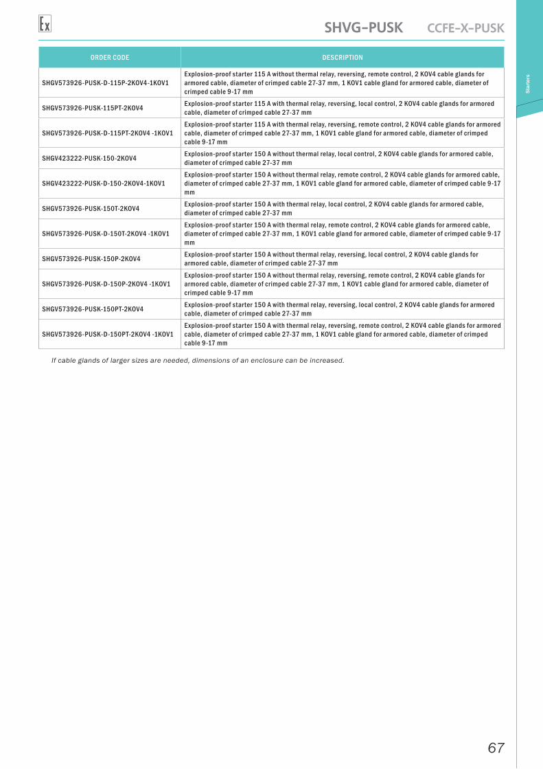
ORDER CODE DESCRIPTION
SHGV573926-PUSK-D-115Р-2KOV4-1KOV1Explosion-proof starter 115 A without thermal relay, reversing, remote control, 2 KOV4 cable glands for armored cable, diameter of crimped cable 27-37 mm, 1 KOV1 cable gland for armored cable, diameter of crimped cable 9-17 mm
SHGV573926-PUSK-115РТ-2KOV4 Explosion-proof starter 115 A with thermal relay, reversing, local control, 2 KOV4 cable glands for armored cable, diameter of crimped cable 27-37 mm
SHGV573926-PUSK-D-115РТ-2KOV4 -1KOV1Explosion-proof starter 115 A with thermal relay, reversing, remote control, 2 KOV4 cable glands for armored cable, diameter of crimped cable 27-37 mm, 1 KOV1 cable gland for armored cable, diameter of crimped cable 9-17 mm
SHGV423222-PUSK-150-2KOV4 Explosion-proof starter 150 A without thermal relay, local control, 2 KOV4 cable glands for armored cable, diameter of crimped cable 27-37 mm
SHGV423222-PUSK-D-150-2KOV4-1KOV1Explosion-proof starter 150 A without thermal relay, remote control, 2 KOV4 cable glands for armored cable, diameter of crimped cable 27-37 mm, 1 KOV1 cable gland for armored cable, diameter of crimped cable 9-17 mm
SHGV573926-PUSK-150Т-2KOV4 Explosion-proof starter 150 A with thermal relay, local control, 2 KOV4 cable glands for armored cable, diameter of crimped cable 27-37 mm
SHGV573926-PUSK-D-150Т-2KOV4 -1KOV1Explosion-proof starter 150 A with thermal relay, remote control, 2 KOV4 cable glands for armored cable, diameter of crimped cable 27-37 mm, 1 KOV1 cable gland for armored cable, diameter of crimped cable 9-17 mm
SHGV573926-PUSK-150Р-2KOV4 Explosion-proof starter 150 A without thermal relay, reversing, local control, 2 KOV4 cable glands for armored cable, diameter of crimped cable 27-37 mm
SHGV573926-PUSK-D-150Р-2KOV4 -1KOV1Explosion-proof starter 150 A without thermal relay, reversing, remote control, 2 KOV4 cable glands for armored cable, diameter of crimped cable 27-37 mm, 1 KOV1 cable gland for armored cable, diameter of crimped cable 9-17 mm
SHGV573926-PUSK-150РТ-2KOV4 Explosion-proof starter 150 A with thermal relay, reversing, local control, 2 KOV4 cable glands for armored cable, diameter of crimped cable 27-37 mm
SHGV573926-PUSK-D-150РТ-2KOV4 -1KOV1Explosion-proof starter 150 A with thermal relay, reversing, remote control, 2 KOV4 cable glands for armored cable, diameter of crimped cable 27-37 mm, 1 KOV1 cable gland for armored cable, diameter of crimped cable 9-17 mm
If cable glands of larger sizes are needed, dimensions of an enclosure can be increased.
68
DatasheetC
ontr
ol b
oard
s an
d ca
bine
ts
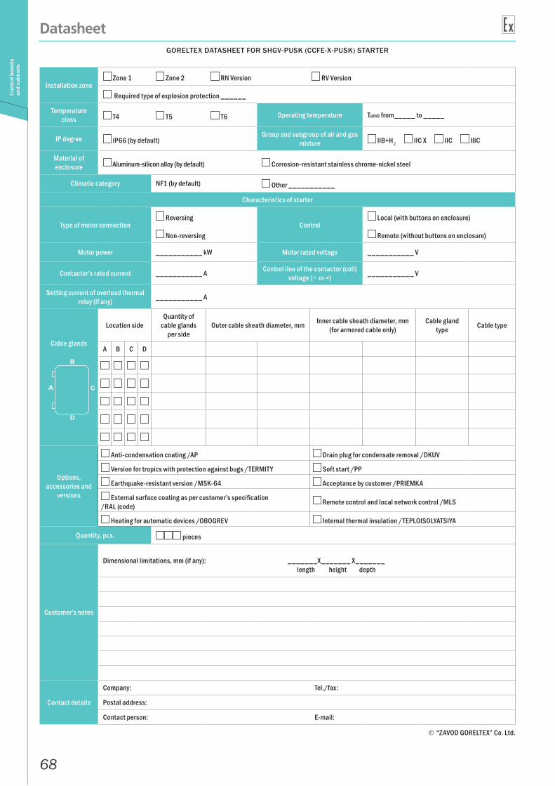
GORELTEX DATASHEET FOR SHGV-PUSK (CCFE-X-PUSK) STARTER
Installation zone Zone 1 Zone 2 RN Version RV Version
Required type of explosion protection ______
Temperature class Т4 T5 T6 Operating temperature Tamb from_____ to _____
IP degree IP66 (by default)Group and subgroup of air and gas
mixture IIB+H2 IIC X IIC IIIC
Material of enclosure Aluminum-silicon alloy (by default) Corrosion-resistant stainless chrome-nickel steel
Climatic category NF1 (by default) Other ___________
Characteristics of starter
Type of motor connection Reversing
Control Local (with buttons on enclosure)
Non-reversing Remote (without buttons on enclosure)
Motor power ___________ kW Motor rated voltage ___________ V
Contactor’s rated current ___________ А Control line of the contactor (coil) voltage (~ or =) ___________ V
Setting current of overload thermal relay (if any) ___________ А
Cable glands
Location side Quantity of
cable glands per side
Outer cable sheath diameter, mm Inner cable sheath diameter, mm (for armored cable only)
Cable gland type Cable type
A B C D
Options, accessories and
versions
Anti-condensation coating /AP Drain plug for condensate removal /DKUV
Version for tropics with protection against bugs /TERMITY Soft start /PP
Earthquake-resistant version /MSK-64 Acceptance by customer /PRIEMKA
External surface coating as per customer’s specification /RAL (code) Remote control and local network control /MLS
Heating for automatic devices /OBOGREV Internal thermal insulation /TEPLOISOLYATSIYA
Quantity, pcs. pieces
Customer’s notes
Dimensional limitations, mm (if any): _______Х_______ Х_______length height depth
Contact details
Company: Tel./fax:
Postal address:
Contact person: E-mail:
“ZAVOD GORELTEX” Co. Ltd.
B
C
D
69
SHGV-UPP CCFE-SOFTSTAR
Star
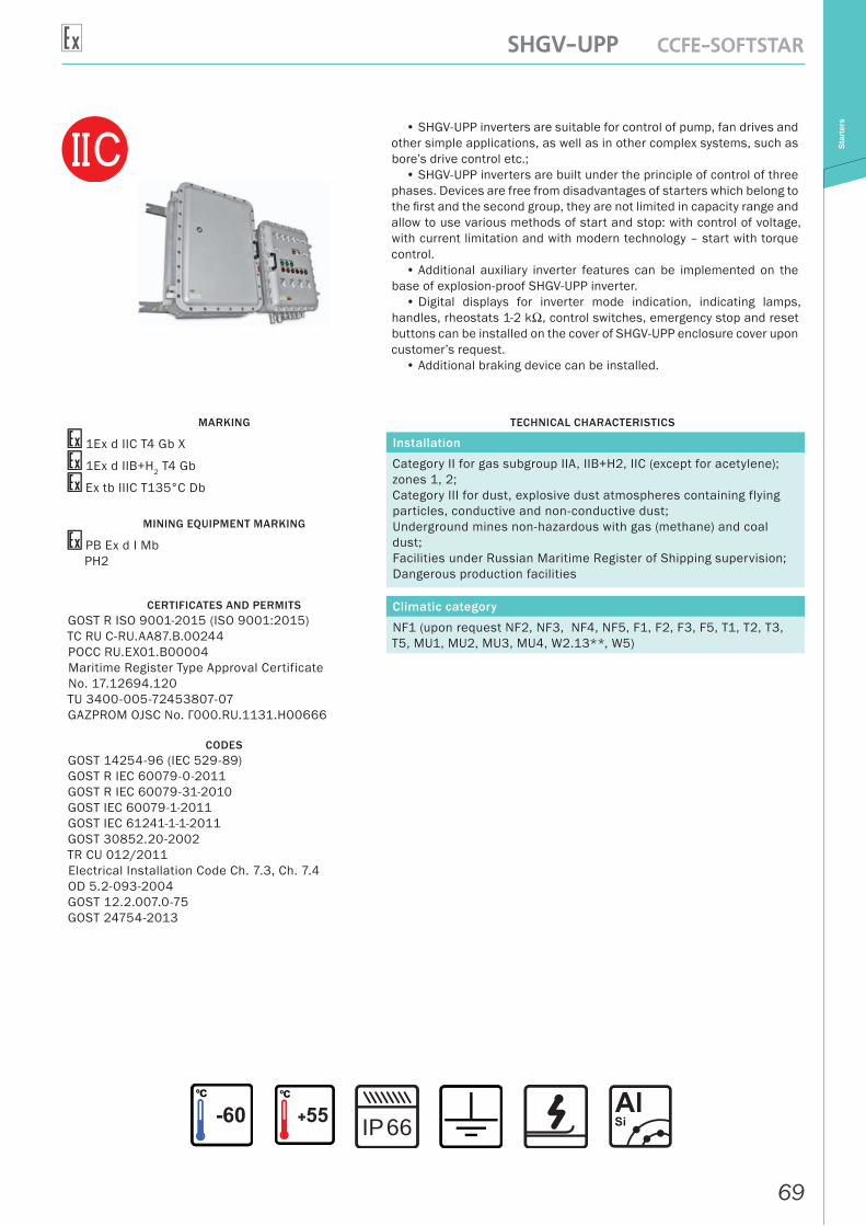
ters• SHGV-UPP inverters are suitable for control of pump, fan drives and
other simple applications, as well as in other complex systems, such as bore’s drive control etc.;
• SHGV-UPP inverters are built under the principle of control of three phases. Devices are free from disadvantages of starters which belong to the first and the second group, they are not limited in capacity range and allow to use various methods of start and stop: with control of voltage, with current limitation and with modern technology – start with torque control.
• Additional auxiliary inverter features can be implemented on the base of explosion-proof SHGV-UPP inverter.
• Digital displays for inverter mode indication, indicating lamps, handles, rheostats 1-2 kΩ, control switches, emergency stop and reset buttons can be installed on the cover of SHGV-UPP enclosure cover upon customer’s request.
• Additional braking device can be installed.
MARKING
1Ex d IIС T4 Gb X
1Ex d IIB+H2 T4 Gb
Ex tb IIIC T135°С Db
MINING EQUIPMENT MARKING
РВ Ex d I MbРН2
CERTIFICATES AND PERMITSGOST R ISO 9001-2015 (ISO 9001:2015)ТС RU С-RU.AA87.В.00244РОСС RU.EX01.B00004Maritime Register Type Approval Certificate No. 17.12694.120TU 3400-005-72453807-07GAZPROM OJSC No. Г000.RU.1131.H00666
CODESGOST 14254-96 (IEC 529-89)GOST R IEC 60079-0-2011GOST R IEC 60079-31-2010GOST IEC 60079-1-2011GOST IEC 61241-1-1-2011GOST 30852.20-2002TR CU 012/2011Electrical Installation Code Ch. 7.3, Ch. 7.4OD 5.2-093-2004GOST 12.2.007.0-75GOST 24754-2013
TECHNICAL CHARACTERISTICS
Installation
Category II for gas subgroup IIA, IIB+H2, IIC (except for acetylene); zones 1, 2;Category III for dust, explosive dust atmospheres containing flying particles, conductive and non-conductive dust;Underground mines non-hazardous with gas (methane) and coal dust;Facilities under Russian Maritime Register of Shipping supervision;Dangerous production facilities
Climatic category
NF1 (upon request NF2, NF3, NF4, NF5, F1, F2, F3, F5, T1, T2, T3, T5, MU1, MU2, MU3, MU4, W2.13**, W5)
66IP
70
SHGV-UPP CCFE-SOFTSTARSt
arte
rs
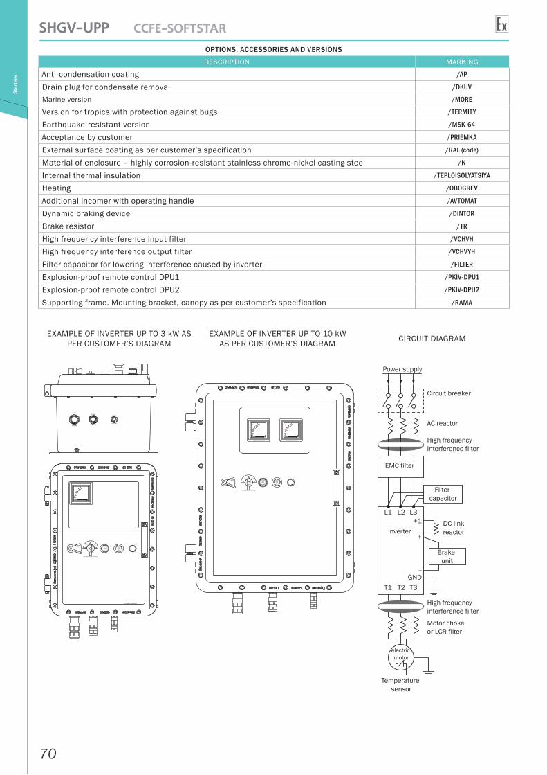
OPTIONS, ACCESSORIES AND VERSIONS
DESCRIPTION MARKING
Anti-condensation coating /AP
Drain plug for condensate removal /DKUV
Marine version /MORE
Version for tropics with protection against bugs /TERMITY
Earthquake-resistant version /MSK-64
Acceptance by customer /PRIEMKA
External surface coating as per customer’s specification /RAL (code)
Material of enclosure – highly corrosion-resistant stainless chrome-nickel casting steel /N
Internal thermal insulation /TEPLOISOLYATSIYA
Heating /OBOGREV
Additional incomer with operating handle /AVTOMAT
Dynamic braking device /DINTOR
Brake resistor /TR
High frequency interference input filter /VCHVH
High frequency interference output filter /VCHVYH
Filter capacitor for lowering interference caused by inverter /FILTER
Explosion-proof remote control DPU1 /PKIV-DPU1
Explosion-proof remote control DPU2 /PKIV-DPU2
Supporting frame. Mounting bracket, canopy as per customer’s specification /RAMA
Power supply
Circuit breaker
AC reactor
High frequency interference filter
EMC filter
Filter capacitor
Inverter
L1 L2 L3+1
+
–GND
T1 T2 T3
High frequency interference filter
DC-link reactor
Brake unit
Motor choke or LCR filter
electric motor
Temperature sensor
EXAMPLE OF INVERTER UP TO 3 kW AS PER CUSTOMER’S DIAGRAM
EXAMPLE OF INVERTER UP TO 10 kW AS PER CUSTOMER’S DIAGRAM CIRCUIT DIAGRAM
71
SHGV-UPP CCFE-SOFTSTAR
Star
ters
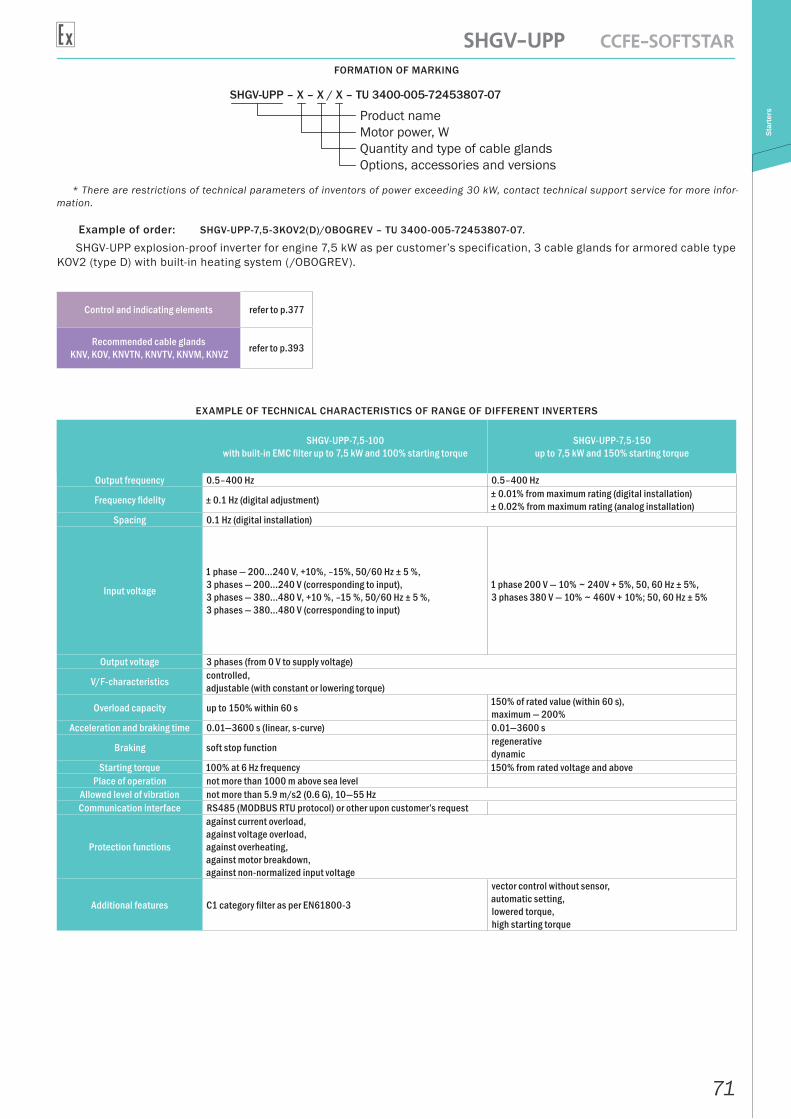
FORMATION OF MARKING
SHGV-UPP – X – X / X – TU 3400-005-72453807-07
Product name Motor power, WQuantity and type of cable glandsOptions, accessories and versions
* There are restrictions of technical parameters of inventors of power exceeding 30 kW, contact technical support service for more infor-mation.
Example of order: SHGV-UPP-7,5-3KOV2(D)/OBOGREV – TU 3400-005-72453807-07.
SHGV-UPP explosion-proof inverter for engine 7,5 kW as per customer’s specification, 3 cable glands for armored cable type KOV2 (type D) with built-in heating system (/OBOGREV).
Control and indicating elements refer to p.377
Recommended cable glands KNV, KOV, KNVTN, KNVTV, KNVM, KNVZ refer to p.393
EXAMPLE OF TECHNICAL CHARACTERISTICS OF RANGE OF DIFFERENT INVERTERS
SHGV-UPP-7,5-100with built-in EMC filter up to 7,5 kW and 100% starting torque
SHGV-UPP-7,5-150up to 7,5 kW and 150% starting torque
Output frequency 0.5–400 Hz 0.5–400 Hz
Frequency fidelity ± 0.1 Hz (digital adjustment) ± 0.01% from maximum rating (digital installation)± 0.02% from maximum rating (analog installation)
Spacing 0.1 Hz (digital installation)
Input voltage
1 phase — 200...240 V, +10%, –15%, 50/60 Hz ± 5 %,3 phases — 200...240 V (corresponding to input),3 phases — 380...480 V, +10 %, –15 %, 50/60 Hz ± 5 %,3 phases — 380...480 V (corresponding to input)
1 phase 200 V — 10% ~ 240V + 5%, 50, 60 Hz ± 5%,3 phases 380 V — 10% ~ 460V + 10%; 50, 60 Hz ± 5%
Output voltage 3 phases (from 0 V to supply voltage)
V/F-characteristics controlled,adjustable (with constant or lowering torque)
Overload capacity up to 150% within 60 s 150% of rated value (within 60 s),maximum — 200%
Acceleration and braking time 0.01—3600 s (linear, s-curve) 0.01—3600 s
Braking soft stop function regenerativedynamic
Starting torque 100% at 6 Hz frequency 150% from rated voltage and abovePlace of operation not more than 1000 m above sea level
Allowed level of vibration not more than 5.9 m/s2 (0.6 G), 10—55 HzCommunication interface RS485 (MODBUS RTU protocol) or other upon customer’s request
Protection functions
against current overload,against voltage overload,against overheating,against motor breakdown,against non-normalized input voltage
Additional features C1 category filter as per EN61800-3
vector control without sensor,automatic setting,lowered torque,high starting torque
72
SHGVA-VA, SHGVA-DVA, SHGVA-UZO CCA-AVT, CCA-DIFAVT, CCA-UZOC
ircui
t bre
aker
s
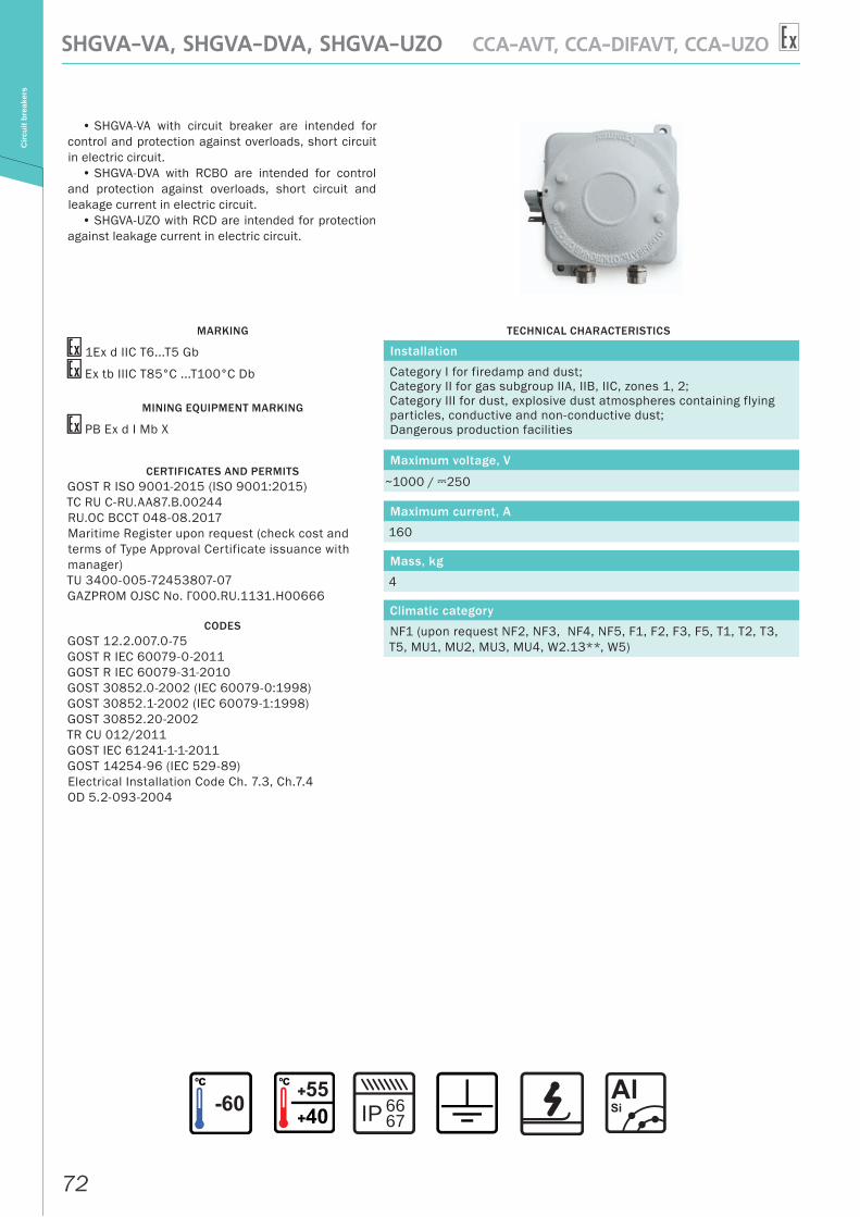
• SHGVA-VA with circuit breaker are intended for control and protection against overloads, short circuit in electric circuit.
• SHGVA-DVA with RCBO are intended for control and protection against overloads, short circuit and leakage current in electric circuit.
• SHGVA-UZO with RCD are intended for protection against leakage current in electric circuit.
MARKING
1Ex d IIC T6...T5 Gb
Ex tb IIIC T85°С ...T100°С Db
MINING EQUIPMENT MARKING
РВ Ex d I Mb X
CERTIFICATES AND PERMITSGOST R ISO 9001-2015 (ISO 9001:2015)ТС RU С-RU.AA87.В.00244RU.OC BCCT 048-08.2017Maritime Register upon request (check cost and terms of Type Approval Certificate issuance with manager)TU 3400-005-72453807-07GAZPROM OJSC No. Г000.RU.1131.H00666
CODESGOST 12.2.007.0-75GOST R IEC 60079-0-2011GOST R IEC 60079-31-2010GOST 30852.0-2002 (IEC 60079-0:1998)GOST 30852.1-2002 (IEC 60079-1:1998)GOST 30852.20-2002TR CU 012/2011GOST IEC 61241-1-1-2011GOST 14254-96 (IEC 529-89)Electrical Installation Code Ch. 7.3, Ch.7.4OD 5.2-093-2004
TECHNICAL CHARACTERISTICS
Installation
Category I for firedamp and dust;Category II for gas subgroup IIA, IIB, IIC, zones 1, 2;Category III for dust, explosive dust atmospheres containing flying particles, conductive and non-conductive dust;Dangerous production facilities
Maximum voltage, V
~1000 / A250
Maximum current, A
160
Mass, kg
4
Climatic category
NF1 (upon request NF2, NF3, NF4, NF5, F1, F2, F3, F5, T1, T2, T3, T5, MU1, MU2, MU3, MU4, W2.13**, W5)
IP 6667
73
SHGVA-VA, SHGVA-DVA, SHGVA-UZO CCA-AVT, CCA-DIFAVT, CCA-UZO
Circ
uit b
reak
ers
OPTIONS, ACCESSORIES AND VERSIONS
DESCRIPTION MARKING
Anti-condensation coating /AP
Drain plug for condensate removal /DKUV
Earthquake-resistant version /MSK-64
Version for tropics with protection against bugs /TERMITY
Acceptance by customer /PRIEMKA
External surface coating as per customer’s specification /RAL (code)
Internal thermal insulation /TEPLOISOLYATSIYA
Heating /OBOGREV
Additional contacts (state contact, signal contact) /DK
Motor drive for remote control /PDU
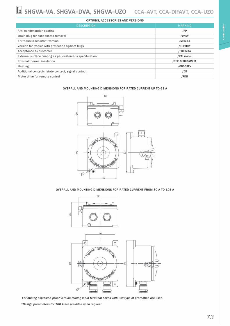
OVERALL AND MOUNTING DIMENSIONS FOR RATED CURRENT UP TO 63 A
OVERALL AND MOUNTING DIMENSIONS FOR RATED CURRENT FROM 80 A TO 125 A
For mining explosion-proof version mining input terminal boxes with Exd type of protection are used.
*Design parameters for 160 A are provided upon request
74
SHGVA-VA, SHGVA-DVA, SHGVA-UZO CCA-AVT, CCA-DIFAVT, CCA-UZOC
ircui
t bre
aker
s
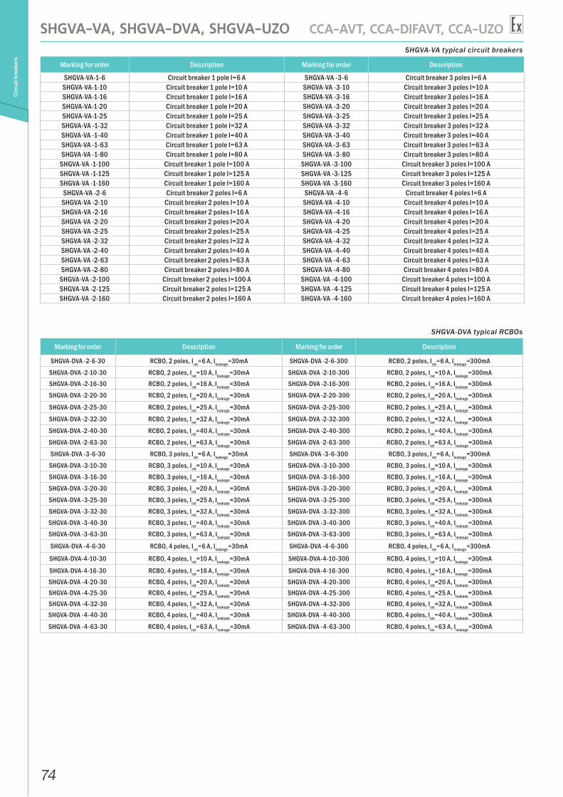
SHGVA-VA typical circuit breakers
Marking for order Description Marking for order Description
SHGVA-VA-1-6 Circuit breaker 1 pole I=6 A SHGVA-VA -3-6 Circuit breaker 3 poles I=6 ASHGVA-VA-1-10 Circuit breaker 1 pole I=10 A SHGVA-VA -3-10 Circuit breaker 3 poles I=10 ASHGVA-VA-1-16 Circuit breaker 1 pole I=16 A SHGVA-VA -3-16 Circuit breaker 3 poles I=16 ASHGVA-VA-1-20 Circuit breaker 1 pole I=20 A SHGVA-VA -3-20 Circuit breaker 3 poles I=20 ASHGVA-VA-1-25 Circuit breaker 1 pole I=25 A SHGVA-VA -3-25 Circuit breaker 3 poles I=25 ASHGVA-VA -1-32 Circuit breaker 1 pole I=32 A SHGVA-VA -3-32 Circuit breaker 3 poles I=32 ASHGVA-VA -1-40 Circuit breaker 1 pole I=40 A SHGVA-VA -3-40 Circuit breaker 3 poles I=40 ASHGVA-VA -1-63 Circuit breaker 1 pole I=63 A SHGVA-VA -3-63 Circuit breaker 3 poles I=63 ASHGVA-VA -1-80 Circuit breaker 1 pole I=80 A SHGVA-VA -3-80 Circuit breaker 3 poles I=80 A
SHGVA-VA -1-100 Circuit breaker 1 pole I=100 A SHGVA-VA -3-100 Circuit breaker 3 poles I=100 ASHGVA-VA -1-125 Circuit breaker 1 pole I=125 A SHGVA-VA -3-125 Circuit breaker 3 poles I=125 ASHGVA-VA -1-160 Circuit breaker 1 pole I=160 A SHGVA-VA -3-160 Circuit breaker 3 poles I=160 A
SHGVA-VA -2-6 Circuit breaker 2 poles I=6 A SHGVA-VA -4-6 Circuit breaker 4 poles I=6 ASHGVA-VA -2-10 Circuit breaker 2 poles I=10 A SHGVA-VA -4-10 Circuit breaker 4 poles I=10 ASHGVA-VA -2-16 Circuit breaker 2 poles I=16 A SHGVA-VA -4-16 Circuit breaker 4 poles I=16 ASHGVA-VA -2-20 Circuit breaker 2 poles I=20 A SHGVA-VA -4-20 Circuit breaker 4 poles I=20 ASHGVA-VA -2-25 Circuit breaker 2 poles I=25 A SHGVA-VA -4-25 Circuit breaker 4 poles I=25 ASHGVA-VA -2-32 Circuit breaker 2 poles I=32 A SHGVA-VA -4-32 Circuit breaker 4 poles I=32 ASHGVA-VA -2-40 Circuit breaker 2 poles I=40 A SHGVA-VA -4-40 Circuit breaker 4 poles I=40 ASHGVA-VA -2-63 Circuit breaker 2 poles I=63 A SHGVA-VA -4-63 Circuit breaker 4 poles I=63 ASHGVA-VA -2-80 Circuit breaker 2 poles I=80 A SHGVA-VA -4-80 Circuit breaker 4 poles I=80 A
SHGVA-VA -2-100 Circuit breaker 2 poles I=100 A SHGVA-VA -4-100 Circuit breaker 4 poles I=100 ASHGVA-VA -2-125 Circuit breaker 2 poles I=125 A SHGVA-VA -4-125 Circuit breaker 4 poles I=125 ASHGVA-VA -2-160 Circuit breaker 2 poles I=160 A SHGVA-VA -4-160 Circuit breaker 4 poles I=160 A
SHGVA-DVA typical RCBOs
Marking for order Description Marking for order Description
SHGVA-DVA -2-6-30 RCBO, 2 poles, Irat=6 A, Ileakage=30mA SHGVA-DVA -2-6-300 RCBO, 2 poles, Irat=6 A, Ileakage=300mA
SHGVA-DVA -2-10-30 RCBO, 2 poles, Irat=10 A, Ileakage=30mA SHGVA-DVA -2-10-300 RCBO, 2 poles, Irat=10 A, Ileakage=300mASHGVA-DVA -2-16-30 RCBO, 2 poles, Irat=16 A, Ileakage=30mA SHGVA-DVA -2-16-300 RCBO, 2 poles, Irat=16 A, Ileakage=300mA
SHGVA-DVA -2-20-30 RCBO, 2 poles, Irat=20 A, Ileakage=30mA SHGVA-DVA -2-20-300 RCBO, 2 poles, Irat=20 A, Ileakage=300mA
SHGVA-DVA -2-25-30 RCBO, 2 poles, Irat=25 A, Ileakage=30mA SHGVA-DVA -2-25-300 RCBO, 2 poles, Irat=25 A, Ileakage=300mA
SHGVA-DVA -2-32-30 RCBO, 2 poles, Irat=32 A, Ileakage=30mA SHGVA-DVA -2-32-300 RCBO, 2 poles, Irat=32 A, Ileakage=300mA
SHGVA-DVA -2-40-30 RCBO, 2 poles, Irat=40 A, Ileakage=30mA SHGVA-DVA -2-40-300 RCBO, 2 poles, Irat=40 A, Ileakage=300mA
SHGVA-DVA -2-63-30 RCBO, 2 poles, Irat=63 A, Ileakage=30mA SHGVA-DVA -2-63-300 RCBO, 2 poles, Irat=63 A, Ileakage=300mA
SHGVA-DVA -3-6-30 RCBO, 3 poles, Irat=6 A, Ileakage=30mA SHGVA-DVA -3-6-300 RCBO, 3 poles, Irat=6 A, Ileakage=300mA
SHGVA-DVA -3-10-30 RCBO, 3 poles, Irat=10 A, Ileakage=30mA SHGVA-DVA -3-10-300 RCBO, 3 poles, Irat=10 A, Ileakage=300mASHGVA-DVA -3-16-30 RCBO, 3 poles, Irat=16 A, Ileakage=30mA SHGVA-DVA -3-16-300 RCBO, 3 poles, Irat=16 A, Ileakage=300mASHGVA-DVA -3-20-30 RCBO, 3 poles, Irat=20 A, Ileakage=30mA SHGVA-DVA -3-20-300 RCBO, 3 poles, Irat=20 A, Ileakage=300mA
SHGVA-DVA -3-25-30 RCBO, 3 poles, Irat=25 A, Ileakage=30mA SHGVA-DVA -3-25-300 RCBO, 3 poles, Irat=25 A, Ileakage=300mASHGVA-DVA -3-32-30 RCBO, 3 poles, Irat=32 A, Ileakage=30mA SHGVA-DVA -3-32-300 RCBO, 3 poles, Irat=32 A, Ileakage=300mASHGVA-DVA -3-40-30 RCBO, 3 poles, Irat=40 A, Ileakage=30mA SHGVA-DVA -3-40-300 RCBO, 3 poles, Irat=40 A, Ileakage=300mASHGVA-DVA -3-63-30 RCBO, 3 poles, Irat=63 A, Ileakage=30mA SHGVA-DVA -3-63-300 RCBO, 3 poles, Irat=63 A, Ileakage=300mA
SHGVA-DVA -4-6-30 RCBO, 4 poles, Irat=6 A, Ileakage=30mA SHGVA-DVA -4-6-300 RCBO, 4 poles, Irat=6 A, Ileakage=300mA
SHGVA-DVA-4-10-30 RCBO, 4 poles, Irat=10 A, Ileakage=30mA SHGVA-DVA-4-10-300 RCBO, 4 poles, Irat=10 A, Ileakage=300mA
SHGVA-DVA-4-16-30 RCBO, 4 poles, Irat=16 A, Ileakage=30mA SHGVA-DVA-4-16-300 RCBO, 4 poles, Irat=16 A, Ileakage=300mASHGVA-DVA -4-20-30 RCBO, 4 poles, Irat=20 A, Ileakage=30mA SHGVA-DVA -4-20-300 RCBO, 4 poles, Irat=20 A, Ileakage=300mASHGVA-DVA -4-25-30 RCBO, 4 poles, Irat=25 A, Ileakage=30mA SHGVA-DVA -4-25-300 RCBO, 4 poles, Irat=25 A, Ileakage=300mASHGVA-DVA -4-32-30 RCBO, 4 poles, Irat=32 A, Ileakage=30mA SHGVA-DVA -4-32-300 RCBO, 4 poles, Irat=32 A, Ileakage=300mASHGVA-DVA -4-40-30 RCBO, 4 poles, Irat=40 A, Ileakage=30mA SHGVA-DVA -4-40-300 RCBO, 4 poles, Irat=40 A, Ileakage=300mA
SHGVA-DVA -4-63-30 RCBO, 4 poles, Irat=63 A, Ileakage=30mA SHGVA-DVA -4-63-300 RCBO, 4 poles, Irat=63 A, Ileakage=300mA
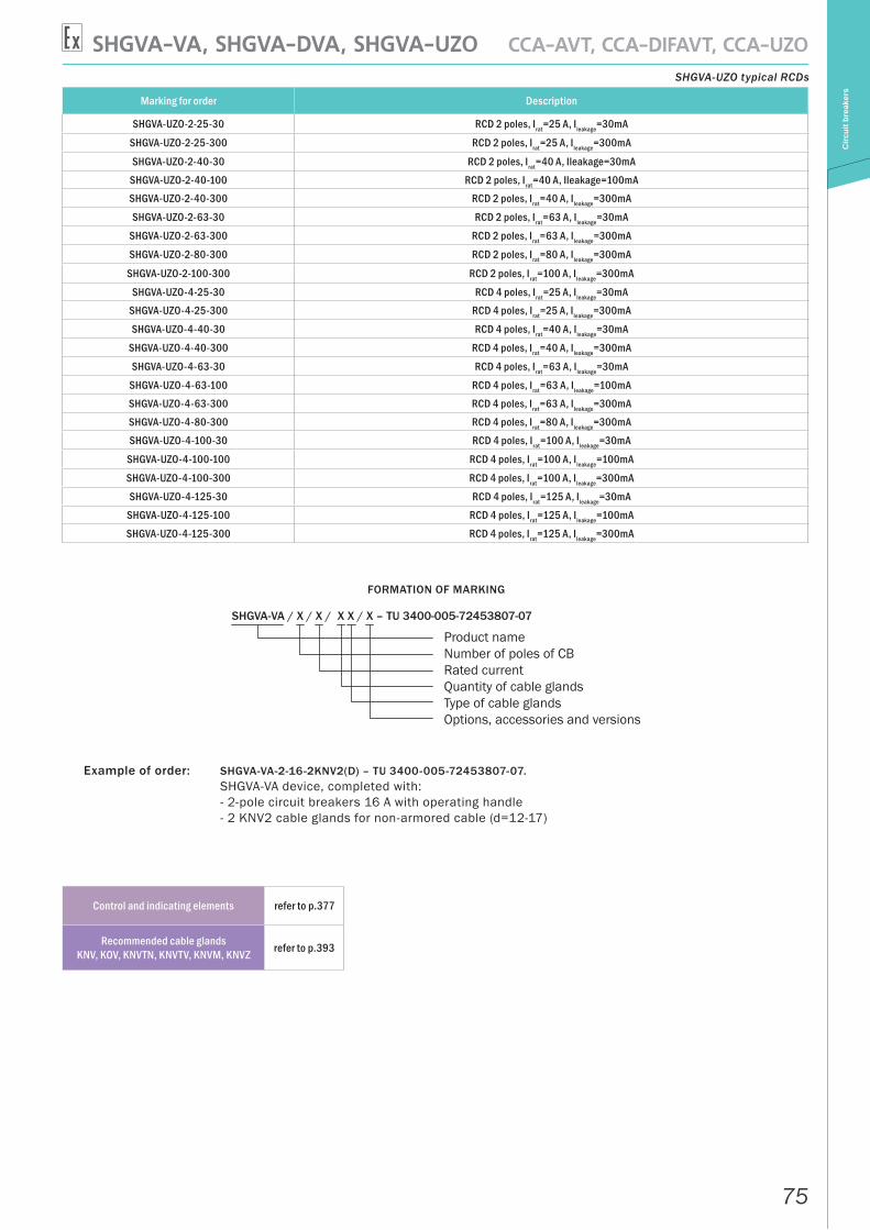
75
SHGVA-VA, SHGVA-DVA, SHGVA-UZO CCA-AVT, CCA-DIFAVT, CCA-UZO
Circ
uit b
reak
ers
SHGVA-UZO typical RCDs
Marking for order Description
SHGVA-UZO-2-25-30 RCD 2 poles, Irat=25 A, Ileakage=30mA
SHGVA-UZO-2-25-300 RCD 2 poles, Irat=25 A, Ileakage=300mA
SHGVA-UZO-2-40-30 RCD 2 poles, Irat=40 A, Ileakage=30mA
SHGVA-UZO-2-40-100 RCD 2 poles, Irat=40 A, Ileakage=100mASHGVA-UZO-2-40-300 RCD 2 poles, Irat=40 A, Ileakage=300mA
SHGVA-UZO-2-63-30 RCD 2 poles, Irat=63 A, Ileakage=30mA
SHGVA-UZO-2-63-300 RCD 2 poles, Irat=63 A, Ileakage=300mA
SHGVA-UZO-2-80-300 RCD 2 poles, Irat=80 A, Ileakage=300mA
SHGVA-UZO-2-100-300 RCD 2 poles, Irat=100 A, Ileakage=300mA
SHGVA-UZO-4-25-30 RCD 4 poles, Irat=25 A, Ileakage=30mASHGVA-UZO-4-25-300 RCD 4 poles, Irat=25 A, Ileakage=300mA
SHGVA-UZO-4-40-30 RCD 4 poles, Irat=40 A, Ileakage=30mA
SHGVA-UZO-4-40-300 RCD 4 poles, Irat=40 A, Ileakage=300mA
SHGVA-UZO-4-63-30 RCD 4 poles, Irat=63 A, Ileakage=30mA
SHGVA-UZO-4-63-100 RCD 4 poles, Irat=63 A, Ileakage=100mASHGVA-UZO-4-63-300 RCD 4 poles, Irat=63 A, Ileakage=300mASHGVA-UZO-4-80-300 RCD 4 poles, Irat=80 A, Ileakage=300mASHGVA-UZO-4-100-30 RCD 4 poles, Irat=100 A, Ileakage=30mA
SHGVA-UZO-4-100-100 RCD 4 poles, Irat=100 A, Ileakage=100mA
SHGVA-UZO-4-100-300 RCD 4 poles, Irat=100 A, Ileakage=300mA
SHGVA-UZO-4-125-30 RCD 4 poles, Irat=125 A, Ileakage=30mASHGVA-UZO-4-125-100 RCD 4 poles, Irat=125 A, Ileakage=100mA
SHGVA-UZO-4-125-300 RCD 4 poles, Irat=125 A, Ileakage=300mA
FORMATION OF MARKING
SHGVA-VA / X / X / X X / X – TU 3400-005-72453807-07
Product nameNumber of poles of CB Rated currentQuantity of cable glandsType of cable glandsOptions, accessories and versions
Example of order: SHGVA-VA-2-16-2KNV2(D) – TU 3400-005-72453807-07. SHGVA-VA device, completed with: - 2-pole circuit breakers 16 A with operating handle - 2 KNV2 cable glands for non-armored cable (d=12-17)
Control and indicating elements refer to p.377
Recommended cable glands KNV, KOV, KNVTN, KNVTV, KNVM, KNVZ refer to p.393
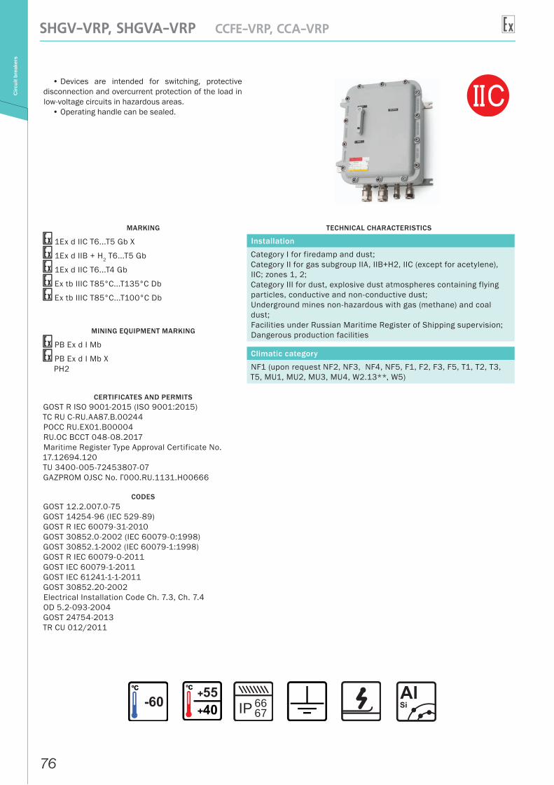
76
SHGV-VRP, SHGVA-VRP CCFE-VRP, CCA-VRPC
ircui
t bre
aker
s
• Devices are intended for switching, protective disconnection and overcurrent protection of the load in low-voltage circuits in hazardous areas.
• Operating handle can be sealed.
MARKING
1Ex d IIC T6...T5 Gb X
1Ex d IIB + H2 T6...T5 Gb
1Ex d IIC T6...T4 Gb
Ex tb IIIC T85°С...T135°С Db
Ex tb IIIC T85°C...T100°C Db
MINING EQUIPMENT MARKING
РВ Ex d I Mb
РВ Ex d I Mb XРН2
CERTIFICATES AND PERMITSGOST R ISO 9001-2015 (ISO 9001:2015)ТС RU С-RU.AA87.В.00244РОСС RU.EX01.B00004RU.OC BCCT 048-08.2017Maritime Register Type Approval Certificate No. 17.12694.120TU 3400-005-72453807-07GAZPROM OJSC No. Г000.RU.1131.H00666
CODESGOST 12.2.007.0-75GOST 14254-96 (IEC 529-89)GOST R IEC 60079-31-2010GOST 30852.0-2002 (IEC 60079-0:1998)GOST 30852.1-2002 (IEC 60079-1:1998)GOST R IEC 60079-0-2011GOST IEC 60079-1-2011GOST IEC 61241-1-1-2011GOST 30852.20-2002Electrical Installation Code Ch. 7.3, Ch. 7.4OD 5.2-093-2004GOST 24754-2013TR CU 012/2011
TECHNICAL CHARACTERISTICS
Installation
Category I for firedamp and dust; Category II for gas subgroup IIA, IIB+H2, IIC (except for acetylene), IIC; zones 1, 2;Category III for dust, explosive dust atmospheres containing flying particles, conductive and non-conductive dust;Underground mines non-hazardous with gas (methane) and coal dust;Facilities under Russian Maritime Register of Shipping supervision;Dangerous production facilities
Climatic category
NF1 (upon request NF2, NF3, NF4, NF5, F1, F2, F3, F5, T1, T2, T3, T5, MU1, MU2, MU3, MU4, W2.13**, W5)
IP 6667

77
SHGV-VRP, SHGVA-VRP CCFE-VRP, CCA-VRP
Circ
uit b
reak
ers
OPTIONS, ACCESSORIES AND VERSIONS
DESCRIPTION MARKING
Anti-condensation coating /AP
Drain plug for condensate removal /DKUV
Version for tropics with protection against bugs /TERMITY
Marine version /MORE
Earthquake-resistant version /MSK-64
Acceptance by customer /PRIEMKA
External surface coating as per customer’s specification /RAL (code)
Internal thermal insulation /TEPLOISOLYATSIYA
Heating /OBOGREV
OVERALL AND MOUNTING DIMENSIONS FOR SHGV-VRP
For mining explosion-proof version mining input terminal boxes with Exd type of protection are used.
Name Number of poles Rated current Dimension type of
fuse-linkDimensions (not including cable glands)
A B CSHGV-VRP-3P-32-… 3 32 C… 304 204 211
SHGV-VRP-3P+N-32-… 4 32 C… 304 204 211SHGV-VRP-3P-50-… 3 50 E… 364 284 215SHGV-VRP-4P-50-… 4 50 E… 364 284 215
SHGV-VRP-3P-100-… 3 100 F… 425 325 226SHGV-VRP-4P-100-… 4 100 F… 425 325 226SHGV-VRP-3P-160-… 3 160 G… 576 396 268SHGV-VRP-4P-160-… 4 160 G… 576 396 268SHGV-VRP-3P-250-… 3 250 H… 650 450 265SHGV-VRP-4P-250-… 4 250 H… 650 450 265SHGV-VRP-3P-400-… 3 400 J… 891 671 455SHGV-VRP-4P-400-… 4 400 J… 891 671 455SHGV-VRP-3P-630-… 3 630 K… 891 671 455SHGV-VRP-4P-630-… 4 630 K… 891 671 455
SHGV-VRP-3P-1250-… 3 1250 L… 1000 700 500
Control and indicating elements refer to p.377
Recommended cable glands KNV, KOV, KNVTN, KNVTV, KNVM, KNVZ refer to p.393
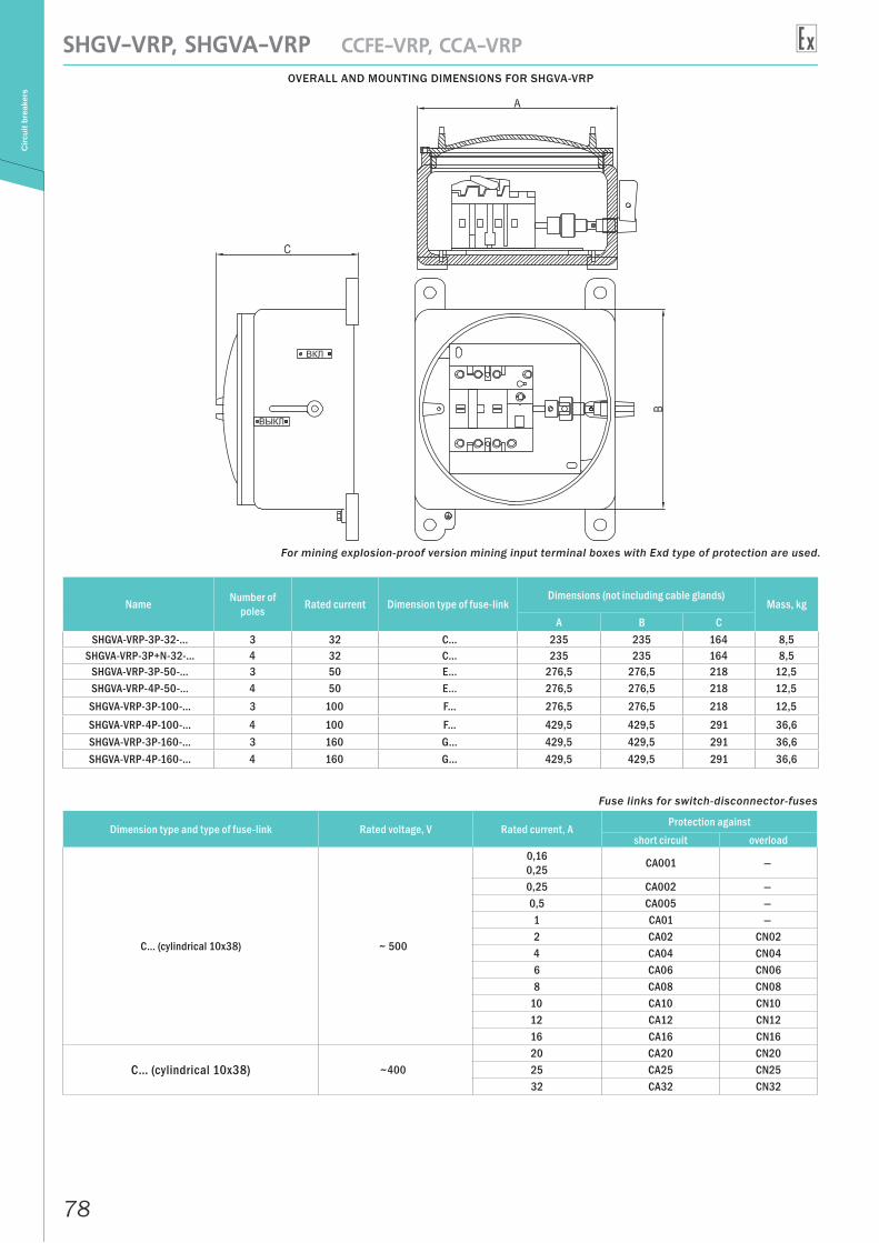
78
SHGV-VRP, SHGVA-VRP CCFE-VRP, CCA-VRPC
ircui
t bre
aker
s
OVERALL AND MOUNTING DIMENSIONS FOR SHGVA-VRP
For mining explosion-proof version mining input terminal boxes with Exd type of protection are used.
Name Number of poles Rated current Dimension type of fuse-link
Dimensions (not including cable glands)Mass, kg
A B CSHGVA-VRP-3P-32-… 3 32 C… 235 235 164 8,5
SHGVA-VRP-3P+N-32-… 4 32 C… 235 235 164 8,5SHGVA-VRP-3P-50-… 3 50 E… 276,5 276,5 218 12,5SHGVA-VRP-4P-50-… 4 50 E… 276,5 276,5 218 12,5
SHGVA-VRP-3P-100-… 3 100 F… 276,5 276,5 218 12,5SHGVA-VRP-4P-100-… 4 100 F… 429,5 429,5 291 36,6SHGVA-VRP-3P-160-… 3 160 G… 429,5 429,5 291 36,6SHGVA-VRP-4P-160-… 4 160 G… 429,5 429,5 291 36,6
Fuse links for switch-disconnector-fuses
Dimension type and type of fuse-link Rated voltage, V Rated current, A Protection againstshort circuit overload
C… (cylindrical 10х38) ~ 500
0,16 0,25 СА001 —
0,25 СА002 —0,5 СА005 —1 СА01 —2 СА02 СN024 СА04 СN046 СА06 СN068 СА08 СN08
10 СА10 СN1012 СА12 СN1216 СА16 СN16
C… (cylindrical 10х38) ~40020 СА20 СN2025 СА25 СN2532 СА32 СN32
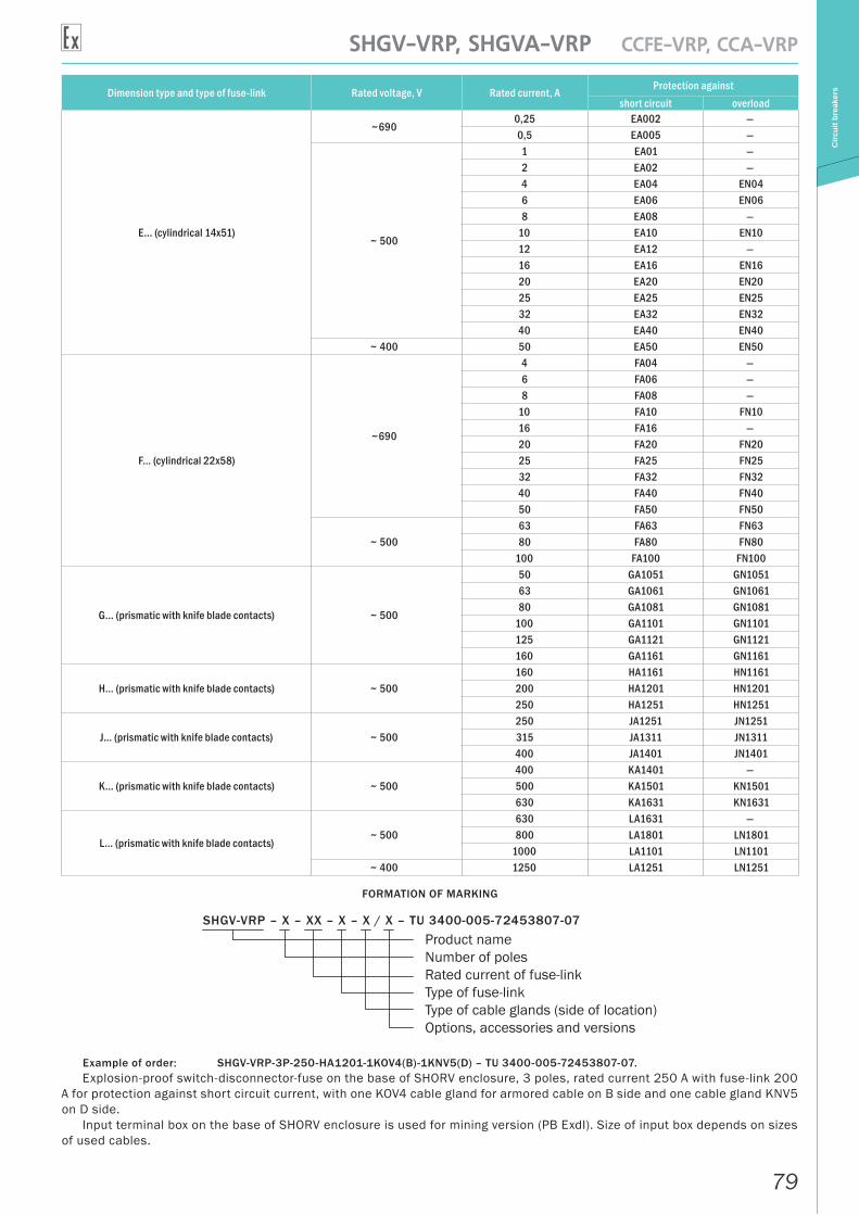
79
SHGV-VRP, SHGVA-VRP CCFE-VRP, CCA-VRP
Circ
uit b
reak
ersDimension type and type of fuse-link Rated voltage, V Rated current, A Protection against
short circuit overload
E… (cylindrical 14х51)
~6900,25 ЕА002 —0,5 ЕА005 —
~ 500
1 ЕА01 —2 ЕА02 —4 ЕА04 ЕN046 ЕА06 ЕN068 ЕА08 —
10 ЕА10 ЕN1012 ЕА12 —16 ЕА16 ЕN1620 ЕА20 ЕN2025 ЕА25 ЕN2532 ЕА32 ЕN3240 ЕА40 ЕN40
~ 400 50 ЕА50 ЕN50
F… (cylindrical 22х58)
~690
4 FА04 —6 FА06 —8 FА08 —
10 FА10 FN1016 FА16 —20 FА20 FN2025 FА25 FN2532 FА32 FN3240 FА40 FN4050 FА50 FN50
~ 50063 FA63 FN6380 FA80 FN80
100 FA100 FN100
G… (prismatic with knife blade contacts) ~ 500
50 GA1051 GN105163 GA1061 GN106180 GA1081 GN1081
100 GA1101 GN1101125 GA1121 GN1121160 GA1161 GN1161
H… (prismatic with knife blade contacts) ~ 500160 HA1161 HN1161200 HA1201 HN1201250 HA1251 HN1251
J… (prismatic with knife blade contacts) ~ 500250 JA1251 JN1251315 JA1311 JN1311400 JA1401 JN1401
K… (prismatic with knife blade contacts) ~ 500400 KA1401 —500 KA1501 KN1501630 KA1631 KN1631
L… (prismatic with knife blade contacts)~ 500
630 LA1631 —800 LA1801 LN1801
1000 LA1101 LN1101~ 400 1250 LA1251 LN1251
FORMATION OF MARKING
SHGV-VRP – X – XX – X – X / X – TU 3400-005-72453807-07Product nameNumber of poles Rated current of fuse-linkType of fuse-linkType of cable glands (side of location)Options, accessories and versions
Example of order: SHGV-VRP-3P-250-HA1201-1KOV4(B)-1KNV5(D) – TU 3400-005-72453807-07.Explosion-proof switch-disconnector-fuse on the base of SHORV enclosure, 3 poles, rated current 250 A with fuse-link 200
A for protection against short circuit current, with one KOV4 cable gland for armored cable on B side and one cable gland KNV5 on D side.
Input terminal box on the base of SHORV enclosure is used for mining version (PB ExdI). Size of input box depends on sizes of used cables.
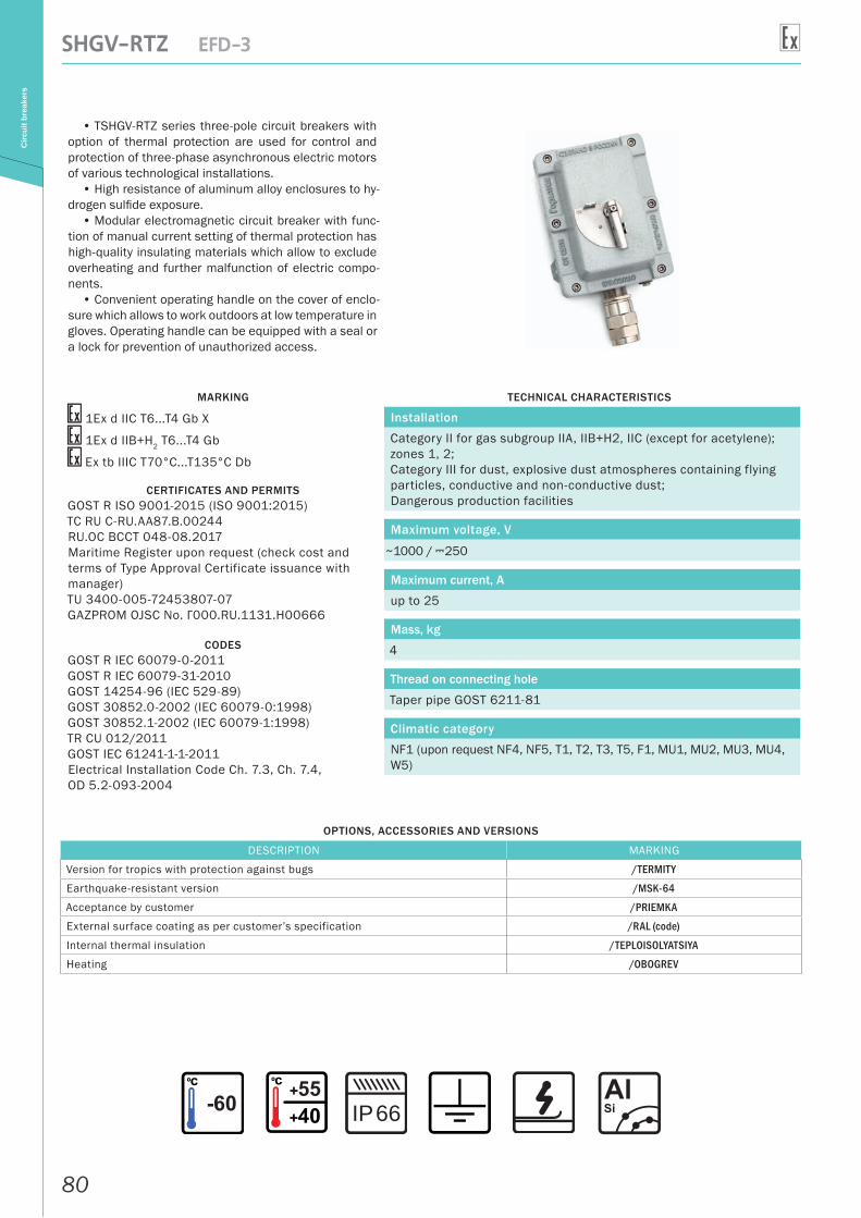
80
SHGV-RTZ EFD-3C
ircui
t bre
aker
s
• ТSHGV-RTZ series three-pole circuit breakers with option of thermal protection are used for control and protection of three-phase asynchronous electric motors of various technological installations.
• High resistance of aluminum alloy enclosures to hy-drogen sulfide exposure.
• Modular electromagnetic circuit breaker with func-tion of manual current setting of thermal protection has high-quality insulating materials which allow to exclude overheating and further malfunction of electric compo-nents.
• Convenient operating handle on the cover of enclo-sure which allows to work outdoors at low temperature in gloves. Operating handle can be equipped with a seal or a lock for prevention of unauthorized access.
MARKING
1Ex d IIС T6...T4 Gb X
1Ex d IIB+H2 T6...T4 Gb
Ex tb IIIС T70°С...T135°С Db
CERTIFICATES AND PERMITSGOST R ISO 9001-2015 (ISO 9001:2015)ТС RU С-RU.AA87.В.00244RU.OC BCCT 048-08.2017Maritime Register upon request (check cost and terms of Type Approval Certificate issuance with manager)TU 3400-005-72453807-07GAZPROM OJSC No. Г000.RU.1131.H00666
CODESGOST R IEC 60079-0-2011GOST R IEC 60079-31-2010GOST 14254-96 (IEC 529-89)GOST 30852.0-2002 (IEC 60079-0:1998)GOST 30852.1-2002 (IEC 60079-1:1998)TR CU 012/2011GOST IEC 61241-1-1-2011Electrical Installation Code Ch. 7.3, Ch. 7.4, OD 5.2-093-2004
TECHNICAL CHARACTERISTICS
Installation
Category II for gas subgroup IIA, IIB+H2, IIC (except for acetylene); zones 1, 2;Category III for dust, explosive dust atmospheres containing flying particles, conductive and non-conductive dust;Dangerous production facilities
Maximum voltage, V
~1000 / A250
Maximum current, A
up to 25
Mass, kg
4
Thread on connecting hole
Taper pipe GOST 6211-81
Climatic category
NF1 (upon request NF4, NF5, T1, T2, T3, T5, F1, MU1, MU2, MU3, MU4, W5)
OPTIONS, ACCESSORIES AND VERSIONS
DESCRIPTION MARKING
Version for tropics with protection against bugs /TERMITY
Earthquake-resistant version /MSK-64
Acceptance by customer /PRIEMKA
External surface coating as per customer’s specification /RAL (code)
Internal thermal insulation /TEPLOISOLYATSIYA
Heating /OBOGREV
66IP
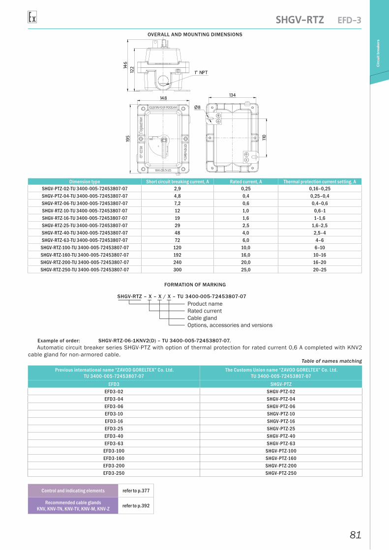
81
SHGV-RTZ EFD-3
Circ
uit b
reak
ers
OVERALL AND MOUNTING DIMENSIONS
146
122
1" NPT
134
110
Ø8
195
148
Dimension type Short circuit breaking current, A Rated current, A Thermal protection current setting, ASHGV-PTZ-02-TU 3400-005-72453807-07 2,9 0,25 0,16–0,25 SHGV-PTZ-04-TU 3400-005-72453807-07 4,8 0,4 0,25–0,4 SHGV-RTZ-06-TU 3400-005-72453807-07 7,2 0,6 0,4–0,6 SHGV-RTZ-10-TU 3400-005-72453807-07 12 1,0 0,6–1 SHGV-RTZ-16-TU 3400-005-72453807-07 19 1,6 1–1,6 SHGV-RTZ-25-TU 3400-005-72453807-07 29 2,5 1,6–2,5 SHGV-RTZ-40-TU 3400-005-72453807-07 48 4,0 2,5–4 SHGV-RTZ-63-TU 3400-005-72453807-07 72 6,0 4–6
SHGV-RTZ-100-TU 3400-005-72453807-07 120 10,0 6–10 SHGV-RTZ-160-TU 3400-005-72453807-07 192 16,0 10–16 SHGV-RTZ-200-TU 3400-005-72453807-07 240 20,0 16–20 SHGV-RTZ-250-TU 3400-005-72453807-07 300 25,0 20–25
FORMATION OF MARKING
SHGV-RTZ – X – X / X – TU 3400-005-72453807-07Product nameRated currentCable glandOptions, accessories and versions
Example of order: SHGV-RTZ-06-1KNV2(D) – TU 3400-005-72453807-07.Automatic circuit breaker series SHGV-PTZ with option of thermal protection for rated current 0,6 A completed with KNV2
cable gland for non-armored cable.Table of names matching
Previous international name “ZAVOD GORELTEX” Co. Ltd.TU 3400-005-72453807-07
The Customs Union name “ZAVOD GORELTEX” Co. Ltd.TU 3400-005-72453807-07
EFD3 SHGV-PTZEFD3-02 SHGV-PTZ-02EFD3-04 SHGV-PTZ-04EFD3-06 SHGV-PTZ-06EFD3-10 SHGV-PTZ-10EFD3-16 SHGV-PTZ-16EFD3-25 SHGV-PTZ-25EFD3-40 SHGV-PTZ-40EFD3-63 SHGV-PTZ-63
EFD3-100 SHGV-PTZ-100EFD3-160 SHGV-PTZ-160EFD3-200 SHGV-PTZ-200EFD3-250 SHGV-PTZ-250
Control and indicating elements refer to p.377
Recommended cable glands KNV, KNV-TN, KNV-TV, KNV-M, KNV-Z refer to p.392