Embed Size (px)
Citation preview

Control the Workplane
This tutorial outlines the procedures to understand and control the user coordinate system(UCS). You can realign and reorient the UCS to create and modify 3D objects on 2D workplanesand rotate objects in 3D.
Audience: Users new to 3D modeling in AutoCAD 2011
Prerequisites: Working knowledge of 2D drafting
Time to complete: 15 minutes
Objectives■ Understand the use of coordinates in 3D
■ Reorient the UCS to rotate objects
■ Work with the dynamic UCS
Tutorial FilesAll necessary files for this tutorial are located athttp://www.autodesk.com/autocad-tutorials.
Recommended: Before starting the tutorials
1

1 Download the control_workplane.zip fromhttp://www.autodesk.com/autocad-tutorials.
2 Unzip control_workplane.zip to C:\My Documents\Tutorials.
Before Starting This TutorialTo switch to a 3D Modeling workspace
1 On the status bar, at the bottom of the drawing area, click the WorkspaceSwitching button.
2 On the Workspace menu, click 3D Modeling.
The 3D Modeling workspace is displayed. The Workspaces icon in the statusbar indicates that you are now in the 3D Modeling workspace. In thisworkspace, you can access the various commands and tools needed for creating3D drawings.
NOTE For more information about switching workspaces, see the AutoCAD User’sGuide or refer to the AutoCAD 2009 tutorial: Switching Workspaces in AutoCAD2009.
Lesson 1: Work with CoordinatesThe coordinates of the world coordinate system(WCS) define the location ofall objects and the standard views of AutoCAD drawings. However, WCS arepermanent and invisible. It cannot be moved or rotated.
AutoCAD provides a movable coordinate system called the user coordinatesystem(UCS). The XY plane of the UCS is called the workplane. In a drawing,
2 | Control the Workplane

by default WCS and UCS have the same orientation. When you create andmodify objects in a 3D environment, you can move and reorient the UCS in3D modeling view.
Use the right-hand rule to determine the positive axis direction of the Z axis.By rotating your hand, see how the X, Y, and Z axes rotate as you change theUCS.
In this lesson, you will learn how to:
■ Align the workplane with the face of an object
■ Create and modify objects on the workplane of the current UCS
File Name: 41 Stand.dwg
To align the workplane with the face of a 3D object
The left image shows the user coordinate system not alignedto the face plate of the 3D object and the right image shows
Lesson 1: Work with Coordinates | 3
the user coordinate system aligned to the face plate of the3D object.
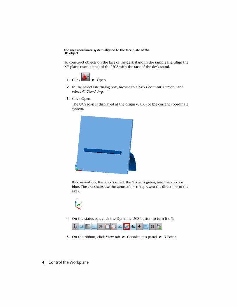
To construct objects on the face of the desk stand in the sample file, align theXY plane (workplane) of the UCS with the face of the desk stand.
1 Click ➤ Open.
2 In the Select File dialog box, browse to C:\My Documents\Tutorials andselect 41 Stand.dwg.
3 Click Open.
The UCS icon is displayed at the origin (0,0,0) of the current coordinatesystem.
By convention, the X axis is red, the Y axis is green, and the Z axis isblue. The crosshairs use the same colors to represent the directions of theaxes.
4 On the status bar, click the Dynamic UCS button to turn it off.
5 On the ribbon, click View tab ➤ Coordinates panel ➤ 3-Point.
4 | Control the Workplane
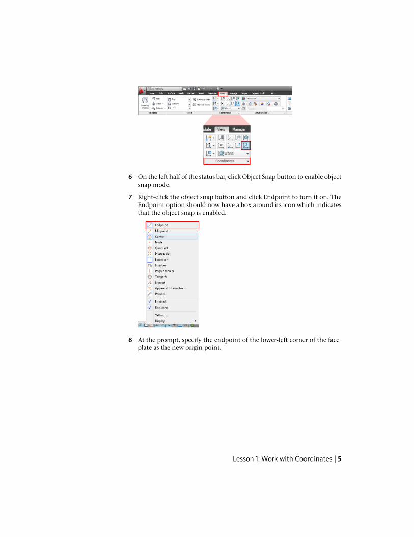
6 On the left half of the status bar, click Object Snap button to enable objectsnap mode.
7 Right-click the object snap button and click Endpoint to turn it on. TheEndpoint option should now have a box around its icon which indicatesthat the object snap is enabled.
8 At the prompt, specify the endpoint of the lower-left corner of the faceplate as the new origin point.
Lesson 1: Work with Coordinates | 5

9 At the prompt, specify the lower-right corner of the face plate.
10 At the prompt, specify the endpoint of the upper-left corner of the faceplate.
6 | Control the Workplane

TIP You can use Zoom on the SteeringWheels tool to magnify the edges ofthe model that are in close proximity to each other. For more informationon SteeringWheels, see the AutoCAD User's Guide. Refer to the AutoCAD 2009tutorial: Navigating a Model with Steering Wheels.
The XY plane (workplane) of the UCS is now aligned to the face of thedesk stand with the origin point (0,0,0) located in the bottom-left corner.
Lesson 1: Work with Coordinates | 7

To create and modify objects when the workplane is aligned to the face of a3D object
On the same drawing 41 Stand.dwg. do the following:
1 On the left half of the status bar, click Ortho to turn it on.
2 Right-click the Object Snap button and click Endpoint, Midpoint,Intersection, and Center to turn them on.
3 On the ribbon, click Home tab ➤ Draw panel ➤ Line.
4 To specify first point, select the midpoint of the top edge of the face plate.
8 | Control the Workplane

5 At the prompt, enter @30<270 and press Enter.
6 At the prompt, enter @35<180 and press Enter. This creates a 35 mm linethat extends to the left at a 180-degree angle.
Lesson 1: Work with Coordinates | 9

7 Press Enter to end the command.
NOTE To change the line color, select the lines, right-click and click Properties.In the Properties palette, under General, select Color and change it to red.
8 On the ribbon, click Home tab ➤ Draw panel ➤ Circle drop-down ➤
Center, Diameter.
9 Select the intersection between the two lines as the center point for circle.
10 | Control the Workplane

10 At the prompt, enter 20 as the diameter of circle and press Enter.
NOTE Coordinate values, such as those of the center of the circle, aremeasured from the new UCS origin.
11 On the ribbon, click Home tab ➤ Draw panel ➤ Rectangle.
Lesson 1: Work with Coordinates | 11
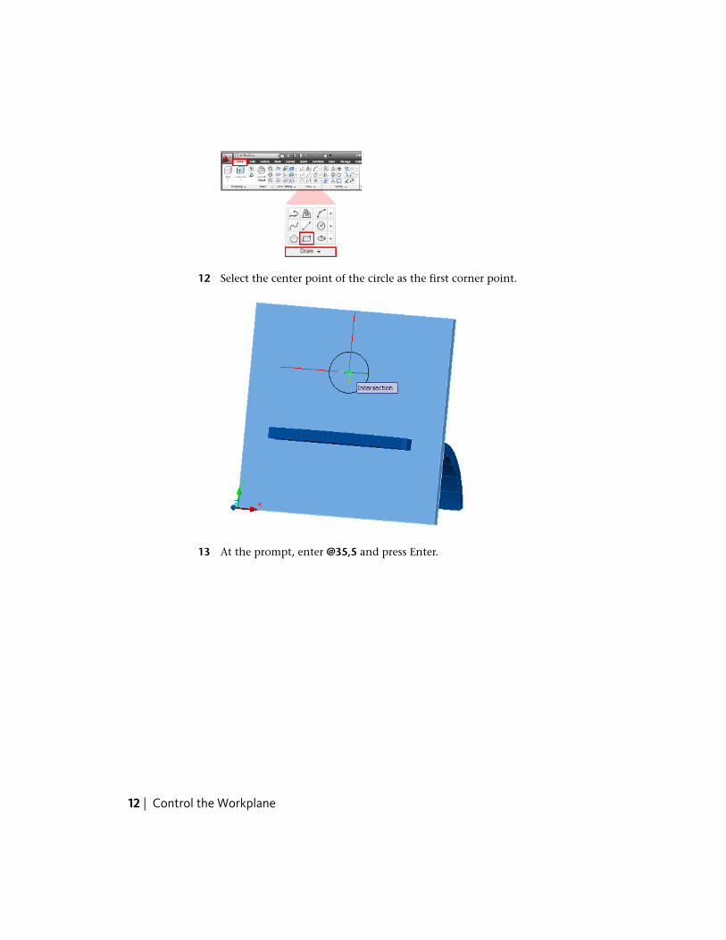
12 Select the center point of the circle as the first corner point.
13 At the prompt, enter @35,5 and press Enter.
12 | Control the Workplane

14 On the ribbon, click Home tab ➤ Modify panel ➤ Rotate.
15 Select the rectangle and press Enter.
TIP If you cannot select the rectangle with the pickbox, enter L and pressEnter to select the last object drawn.
Lesson 1: Work with Coordinates | 13

16 Click the endpoint of the lower-right corner of the rectangle.
17 At the prompt, enter -30 to specify the rotation angle and press Enter.
14 | Control the Workplane

NOTE The rectangle was rotated on the workplane - the axis of rotation isalways perpendicular to the Z axis of the UCS.
18 On the ribbon, click Home tab ➤ Modify panel ➤ ➤ Mirror.
19 Select the rectangle and press Enter.
Lesson 1: Work with Coordinates | 15
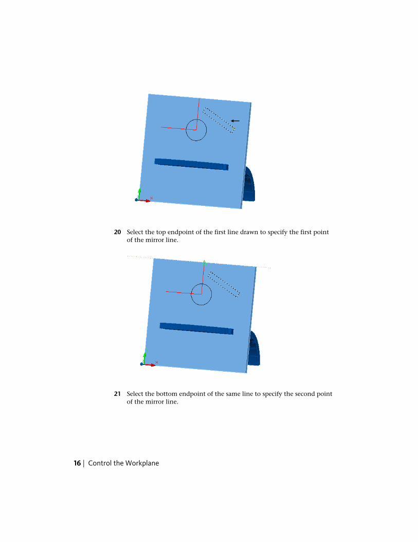
20 Select the top endpoint of the first line drawn to specify the first pointof the mirror line.
21 Select the bottom endpoint of the same line to specify the second pointof the mirror line.
16 | Control the Workplane

22 At the prompt, enter n (No) and press Enter.
A mirror image of the first rectangle is created and aligned to the face ofthe desk stand.
Lesson 1: Work with Coordinates | 17
NOTE Objects created and modified on the face of the desk stand areautomatically aligned to the workplane of the current UCS.
Summary: In this lesson, you learned how to
■ Align the workplane of the UCS to the face of a 3D solid object
■ Create and modify objects that are aligned to the face of the solid objectyou selected
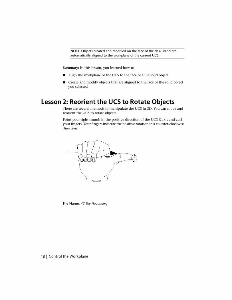
Lesson 2: Reorient the UCS to Rotate ObjectsThere are several methods to manipulate the UCS in 3D. You can move andreorient the UCS to rotate objects.
Point your right thumb in the positive direction of the UCS Z axis and curlyour fingers. Your fingers indicate the positive rotation in a counter-clockwisedirection.
File Name: 42 Toy House.dwg
18 | Control the Workplane

To align the Z axis of the UCS to rotate objects
The positive Z axis of the UCS is aligned perpendicular to the plane in whichthe object was originally created.
The following steps explain how to align the Z axis of the UCS to rotate objects.
1 Click ➤ Open.
2 In the Select File dialog box, browse to C:\My Documents\Tutorials andselect 42 Toy House.dwg.
3 Click Open.
4 On the ribbon, click View tab ➤ Coordinates panel ➤ Z-Axis Vector.
5 Click the endpoint on the top-left outside edge of the red door to specifythe new origin point.
Lesson 2: Reorient the UCS to Rotate Objects | 19

6 Click the endpoint on the top-right outside edge of the red door to specifypoint on positive portion of Z axis.
The UCS origin is moved to the first specified point and its positive Z-axispasses through the second specified point.
7 On the ribbon, click Home tab ➤ Modify panel ➤ Rotate.
20 | Control the Workplane

8 Click the red door and press Enter.
9 Click the midpoint on the outside edge at the top of the red door tospecify the base point.
10 At the prompt, enter -15 as the rotation angle and press Enter.
Lesson 2: Reorient the UCS to Rotate Objects | 21
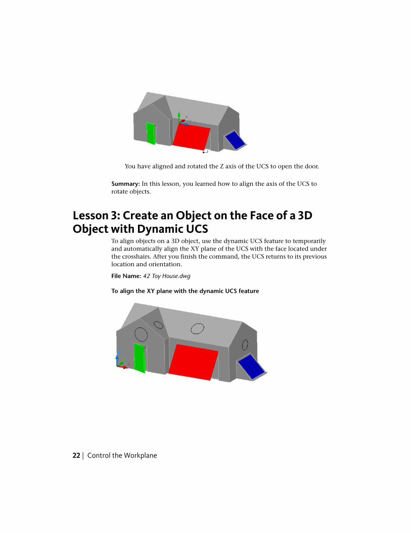
You have aligned and rotated the Z axis of the UCS to open the door.
Summary: In this lesson, you learned how to align the axis of the UCS torotate objects.
Lesson 3: Create an Object on the Face of a 3DObject with Dynamic UCS
To align objects on a 3D object, use the dynamic UCS feature to temporarilyand automatically align the XY plane of the UCS with the face located underthe crosshairs. After you finish the command, the UCS returns to its previouslocation and orientation.
File Name: 42 Toy House.dwg
To align the XY plane with the dynamic UCS feature
22 | Control the Workplane

The following steps explain how to use dynamic UCS to draw a circle to theface of a 3D solid object.
1 Click ➤ Open.
2 In the Select File dialog box, navigate to C:\My Documents\Tutorials andselect 42 Toy House.dwg.
3 Click Open.
4 On the status bar, click the Dynamic UCS button to turn it on.
5 On the ribbon, click Home tab ➤ Draw panel ➤ Circle drop-down ➤
Center, Radius.
6 Click anywhere above the green door to specify the center point of thecircle.
7 At the prompt, enter 0.6 as the radius of circle and press Enter.
NOTE The workplane aligns with each visible face as the crosshairs passesover it.
8 To create more circles as shown in the illustration, right-click the drawingand click Repeat CIRCLE.
Lesson 3: Create an Object on the Face of a 3D Object with Dynamic UCS | 23

9 Specify points anywhere on each plane to create more circles as shownin the illustration.
NOTE After you end the CIRCLE command, the UCS returns to its previouslocation and orientation automatically.
Summary: In this lesson, you learned how to align the UCS with the face ofa 3D object using Dynamic UCS.
Congratulations! You have defined custom UCSs for use with 3D models.
For more information, see the AutoCAD User’s Guide.
24 | Control the Workplane