Embed Size (px)
Citation preview
CONTROLVALVES
POLITICA DELLA QUALITÀ
, attraverso il proprio Sistema di Qualità cer-tificato UNI EN ISO 9001, si prefigge i seguentiobiettivi:� Rafforzare la propria posizione nella progetta-
zione e costruzione di valvole ed apparecchia-ture in genere destinate al mercato nazionaleed internazionale.
� Garantire la soddisfazione delle aspettative deipropri Clienti.
� Ottenere un costante miglioramento qualitativodei propri prodotti.
� Conservare la posizione di fornitore preferitodei propri Clienti.
� Diffondere la propria immagine di azienda forni-trice di prodotti qualitativi di alto livello.
Questi obiettivi sono perseguiti attraverso:� Alti livelli di controllo delle attività aziendali.� Una continua ricerca per lo sviluppo tecnologi-
co delle attività produttive e gestionali.� La sensibilizzazione di ogni settore aziendale e
delle persone che in esso lavorano alla politicadella qualità e agli obiettivi prefissati.
PRODUCE ED ESPORTA IN TUTTO IL MONDO DAL 1951
� Valvole di Sicurezza a Molla
� Valvole di Regolazione a Comando
Pneumatico
� Raccordi ad “Y” con Valvola Deviatrice
(per coppie valvole di sicurezza)
� Valvole Rompivuoto
� Banchi di Taratura Valvole di Sicurezza
MANUFACTURES ANDEXPORTS ALL OVER THEWORLD SINCE 1951
� Spring Loaded Safety-Relief Valves
� Pneumatic Control Valves
� Change-Over Valves
(for Couple of Safety Valves)
� Vacuum Release Valves
� Safety-Relief Valves Test Benches
QUALITY POLICY
By the application of its UNI EN ISO 9001 certi-fied Quality System, pursues the followingaims:� To enforce its position in designing and manu-
facturing of valves and equipment for the dome-stic and intenational market.
� To grant the fulfilment of its Customers expec-tations.
� To obtain a constant quality improvement of itsproducts.
� To preserve its position of preferred supplier ofits Customers.
� To diffuse its image of high quality productssupplier.
These aims are pursued through:� High control of the company activities.� A constant research for the technological deve-
lopment of the managing and production activi-ties.
� The sensitisation of every company departmentand of the people working in it to the qualitypolicy and to the established targets.
1
BASIC FEATURES
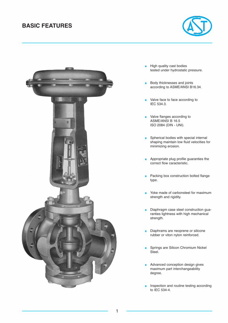
� High quality cast bodiestested under hydrostatic pressure.
� Body thicknesses and jointsaccording to ASME/ANSI B16.34.
� Valve face to face according toIEC 534.3.
� Valve flanges according toASME/ANSI B 16.5ISO 2084 (DIN - UNI).
� Spherical bodies with special internalshaping maintain low fluid velocities forminimizing erosion.
� Appropriate plug profile guaranties thecorrect flow caracteristic.
� Packing box construction bolted flangetype.
� Yoke made of carbonsteel for maximumstrength and rigidity.
� Diaphragm case steel construction gua-ranties lightness with high mechanicalstrength.
� Diaphrams are neoprene or siliconerubber or viton nylon reinforced.
� Springs are Silicon Chromium NickelSteel.
� Advanced conception design givesmaximum part interchangeabilitydegree.
� Inspection and routine testing accordingto IEC 534-4.
2
DIAPHRAGM ACTUATORS
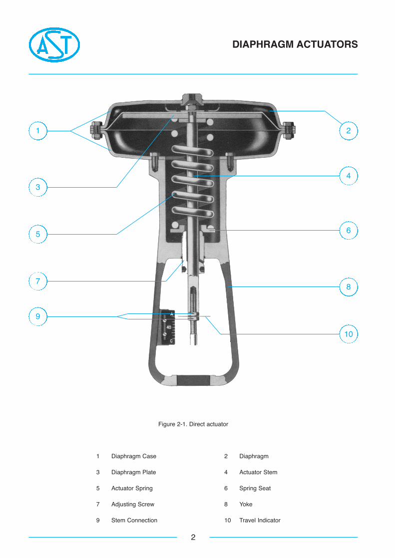
Figure 2-1. Direct actuator
1 Diaphragm Case 2 Diaphragm
3 Diaphragm Plate 4 Actuator Stem
5 Actuator Spring 6 Spring Seat
7 Adjusting Screw 8 Yoke
9 Stem Connection 10 Travel Indicator
3
9
1
5
7
2
4
6
8
10
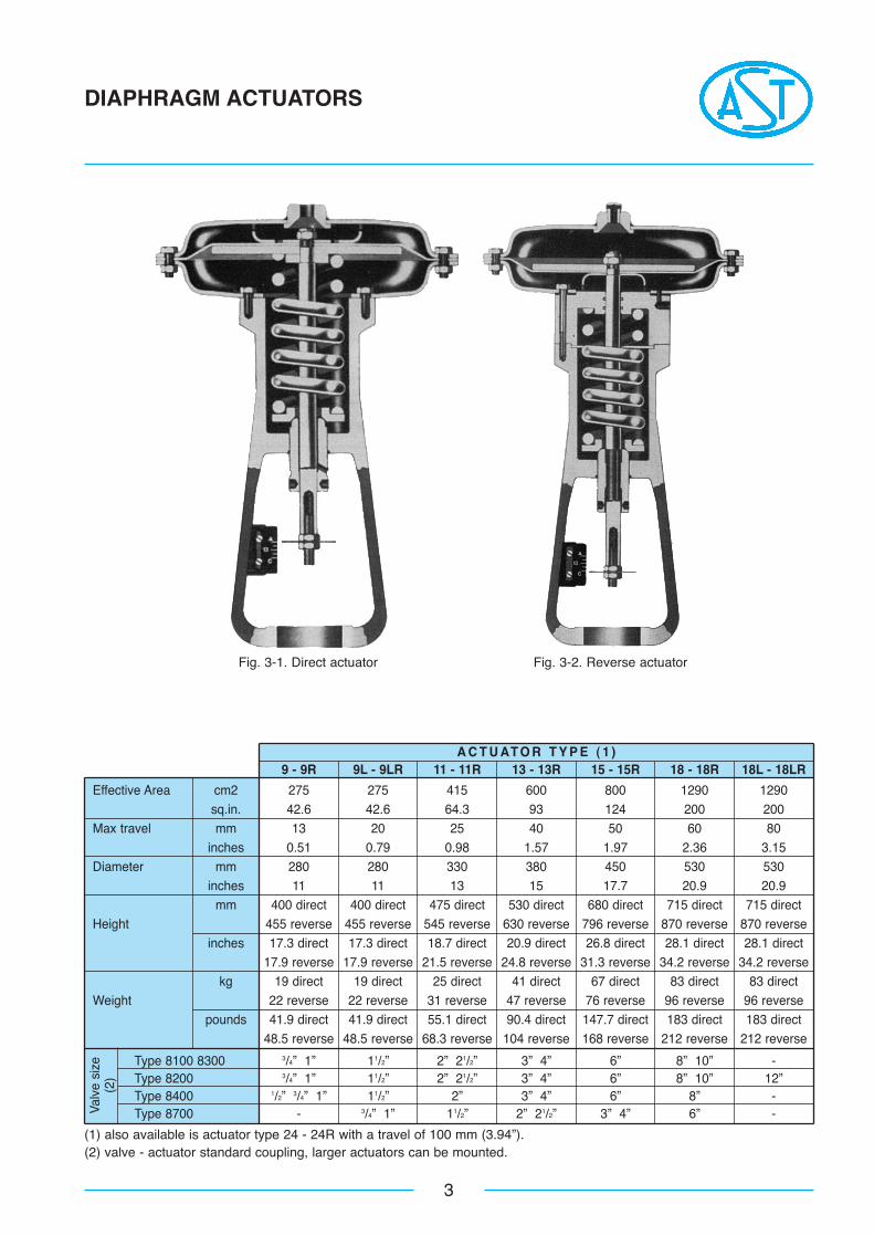
A C T U AT O R T Y P E ( 1 )9 - 9R 9L - 9LR 11 - 11R 13 - 13R 15 - 15R 18 - 18R 18L - 18LR
Effective Area cm2 275 275 415 600 800 1290 1290sq.in. 42.6 42.6 64.3 93 124 200 200
Max travel mm 13 20 25 40 50 60 80inches 0.51 0.79 0.98 1.57 1.97 2.36 3.15
Diameter mm 280 280 330 380 450 530 530inches 11 11 13 15 17.7 20.9 20.9
mm 400 direct 400 direct 475 direct 530 direct 680 direct 715 direct 715 directHeight 455 reverse 455 reverse 545 reverse 630 reverse 796 reverse 870 reverse 870 reverse
inches 17.3 direct 17.3 direct 18.7 direct 20.9 direct 26.8 direct 28.1 direct 28.1 direct17.9 reverse 17.9 reverse 21.5 reverse 24.8 reverse 31.3 reverse 34.2 reverse 34.2 reverse
kg 19 direct 19 direct 25 direct 41 direct 67 direct 83 direct 83 directWeight 22 reverse 22 reverse 31 reverse 47 reverse 76 reverse 96 reverse 96 reverse
pounds 41.9 direct 41.9 direct 55.1 direct 90.4 direct 147.7 direct 183 direct 183 direct48.5 reverse 48.5 reverse 68.3 reverse 104 reverse 168 reverse 212 reverse 212 reverse
Type 8100 8300 3/4” 1” 11/2” 2” 21/2” 3” 4” 6” 8” 10” -Type 8200 3/4” 1” 11/2” 2” 21/2” 3” 4” 6” 8” 10” 12”Type 8400 1/2” 3/4” 1” 11/2” 2” 3” 4” 6” 8” -Type 8700 - 3/4” 1” 11/2” 2” 21/2” 3” 4” 6” -
3
DIAPHRAGM ACTUATORS
(1) also available is actuator type 24 - 24R with a travel of 100 mm (3.94”).(2) valve - actuator standard coupling, larger actuators can be mounted.
Valv
e si
ze(2
)
Fig. 3-1. Direct actuator Fig. 3-2. Reverse actuator
S P R I N G R A N G E ( p s i )3 - 15 6 - 30 12 - 30 15 - 30 18 - 30 3 - 9
Actuator Supply Retracted Extended Retracted Extended Retracted Extended Retracted Extended Retracted Extended Retracted ExtendedType (psi) Stem (N) Stem (N) Stem (N) Stem (N) Stem (N) Stem (N) Stem (N) Stem (N) Stem (N) Stem (N) Stem (N) Stem (N)
20 569 569 - - - - - - - - 569 1707
9 9L 40 569 3984 1138 1138 2277 1138 2846 1138 3415 1138 569 5122
60 569 7399 1138 4553 2277 4553 2846 4553 3415 4553 569 8537
20 859 859 - - - - - - - - 859 2577
11 40 859 6012 1718 1718 3436 1718 4294 1718 5153 1718 859 7730
60 859 11166 1718 6871 3436 6871 4294 6871 5153 6871 859 12883
20 1242 1242 - - - - - - - - 1242 3725
13 40 1242 8692 2484 2484 4967 2484 6209 2484 7451 2484 1242 11176
60 1242 16143 2484 9934 4967 9934 6209 9934 7451 9934 1242 18627
20 1656 1656 - - - - - - - - 1656 4967
15 40 1656 11590 3311 3311 6623 3311 8278 3311 9934 3311 1656 14901
60 1656 21524 3311 13246 6623 13246 8278 13246 9934 13246 1656 24835
20 2670 2670 - - - - - - - - 2670 8009
18 18L 40 2670 18689 5340 5340 10679 5340 13349 5340 16019 5340 2670 24028
60 2670 34708 5340 21358 10679 21358 13349 21358 16019 21358 2670 40047
20 3901 3901 - - - - - - - - 3901 11704
24 40 3901 27309 7802 7802 15605 7802 19506 7802 23407 7802 3901 35111
60 3901 50716 7802 31210 15605 31210 19506 31210 23407 31210 3901 58519
4
DIAPHRAGM ACTUATORS
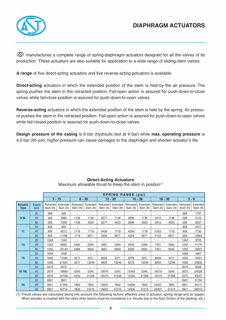
Direct-Acting ActuatorsMaximum allowable thrust to Keep the stem in position(1)
manufactures a complete range of spring-diaphragm actuators designed for all the valves of its
production. These actuators are also suitable for application to a wide range of sliding-stem valves.
A range of five direct-acting actuators and five reverse-acting actuators is available.
Direct-acting actuators in which the extended position of the stem is held by the air pressure. The
spring pushes the stem in the retracted position. Fail-open action is assured for push-down-to-close
valves while fail-close position is assured for push-down-to-open valves.
Reverse-acting actuators in which the extended position of the stem is held by the spring. Air pressu-
re pushes the stem in the retracted position. Fail-open action is assured for push-down-to-open valves
while fail-closed position is assured for push-down-to-close valves.
Design pressure of the casing is 6 bar (hydraulic test at 9 bar) while max. operating pressure is
4,5 bar (65 psi); higher pressure can cause damages to the diaphragm and shorten actuator’s life.
(1) Thrust values are calculated taking into account the following factors: effective area of actuator, spring range and air supply.When actuator is coupled with the valve other factors must be considered (i.e. thrusts due to the fluid, friction of the packing, etc.)
S P R I N G R A N G E ( p s i )3 - 15 6 - 30 12 - 30 15 - 30 18 - 30 3 - 9
Actuator Supply Extended Retracted Extended Retracted Extended Retracted Extended Retracted Extended Retracted Extended RetractedType (psi) Stem (N) Stem (N) Stem (N) Stem (N) Stem (N) Stem (N) Stem (N) Stem (N) Stem (N) Stem (N) Stem (N) Stem (N)
20 569 569 - - - - - - - - 569 1707
9R 9LR 40 569 3984 1138 1138 2277 1138 2846 1138 3415 1138 569 5122
60 569 7399 1138 4553 2277 4553 2846 4553 3415 4553 569 8537
20 859 859 - - - - - - - - 859 2577
11R 40 859 6012 1718 1718 3436 1718 4294 1718 5153 1718 859 7730
60 859 11166 1718 6871 3436 6871 4294 6871 5153 6871 859 12883
20 1242 1242 - - - - - - - - 1242 3725
13R 40 1242 8692 2484 2484 4967 2484 6209 2484 7451 2484 1242 11176
60 1242 16143 2484 9934 4967 9934 6209 9934 7451 9934 1242 18627
20 1656 1656 - - - - - - - - 1656 4967
15R 40 1656 11590 3311 3311 6623 3311 8278 3311 9934 3311 1656 14901
60 1656 21524 3311 13246 6623 13246 8278 13246 9934 13246 1656 24835
20 2670 2670 - - - - - - - - 2670 8009
18R 18LR 40 2670 18689 5340 5340 10679 5340 13349 5340 16019 5340 2670 24028
60 2670 34708 5340 21358 10679 21358 13349 21358 16019 21358 2670 40047
20 3901 3901 - - - - - - - - 3901 11704
24R 40 3901 27309 7802 7802 15605 7802 19506 7802 23407 7802 3901 35111
60 3901 50716 7802 31210 15605 31210 19506 31210 23407 31210 3901 58519
5
DIAPHRAGM ACTUATORS
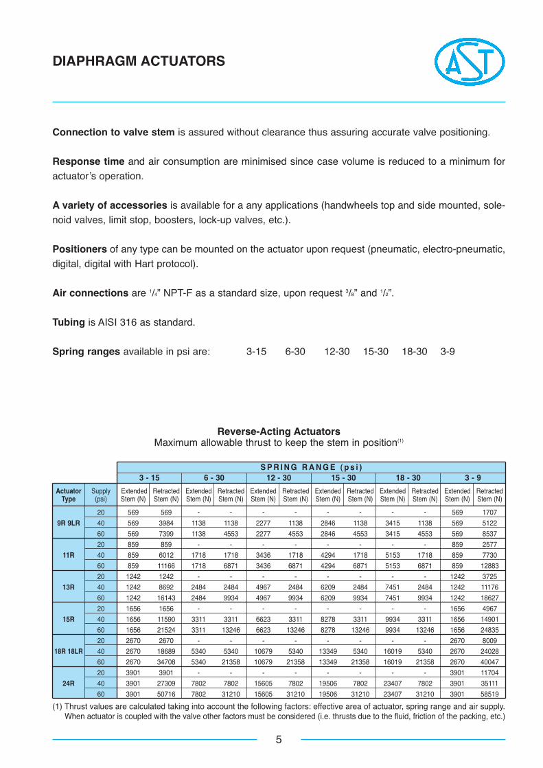
Reverse-Acting ActuatorsMaximum allowable thrust to keep the stem in position(1)
Connection to valve stem is assured without clearance thus assuring accurate valve positioning.
Response time and air consumption are minimised since case volume is reduced to a minimum for
actuator’s operation.
A variety of accessories is available for a any applications (handwheels top and side mounted, sole-
noid valves, limit stop, boosters, lock-up valves, etc.).
Positioners of any type can be mounted on the actuator upon request (pneumatic, electro-pneumatic,
digital, digital with Hart protocol).
Air connections are 1/4” NPT-F as a standard size, upon request 3/8” and 1/2”.
Tubing is AISI 316 as standard.
Spring ranges available in psi are: 3-15 6-30 12-30 15-30 18-30 3-9
(1) Thrust values are calculated taking into account the following factors: effective area of actuator, spring range and air supply.When actuator is coupled with the valve other factors must be considered (i.e. thrusts due to the fluid, friction of the packing, etc.)
6
VALVE BODIES
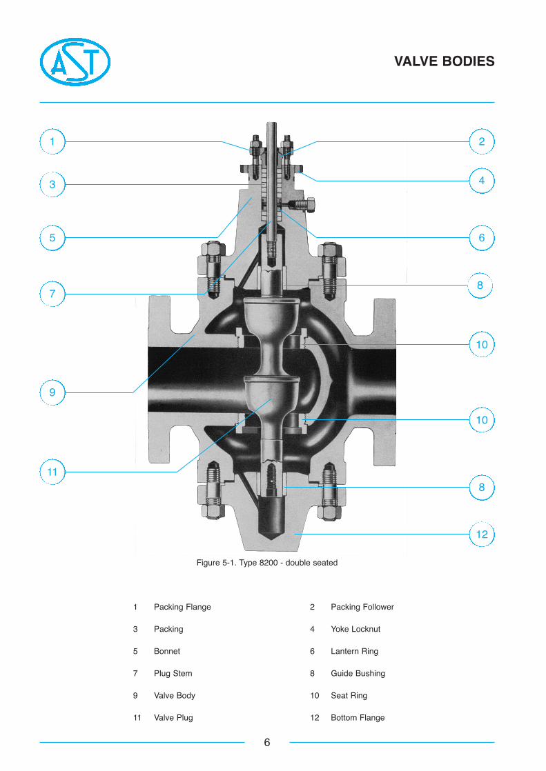
Figure 5-1. Type 8200 - double seated
1 Packing Flange 2 Packing Follower
3 Packing 4 Yoke Locknut
5 Bonnet 6 Lantern Ring
7 Plug Stem 8 Guide Bushing
9 Valve Body 10 Seat Ring
11 Valve Plug 12 Bottom Flange
3
1
5
7
11
9
2
6
8
10
10
8
12
4
7
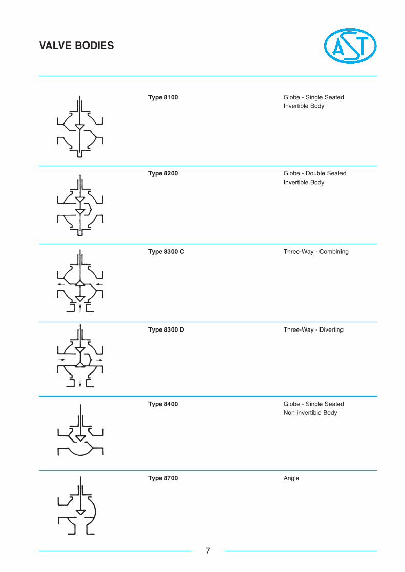
VALVE BODIES
Type 8100 Globe - Single SeatedInvertible Body
Type 8200 Globe - Double SeatedInvertible Body
Type 8300 C Three-Way - Combining
Type 8300 D Three-Way - Diverting
Type 8400 Globe - Single SeatedNon-invertible Body
Type 8700 Angle
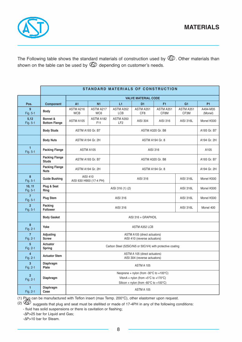
S TA N D A R D M AT E R I A L S O F C O N S T R U C T I O N
8
MATERIALS
The Following table shows the standard materials of construction used by . Other materials than
shown on the table can be used by depending on customer’s needs.
9Body
ASTM A216 ASTM A217 ASTM A352 ASTM A351 ASTM A351 ASTM A351 A494-M35Fig. 5-1 WCB WC6 LCB CF8 CF8M CF3M (Monel)
5,12 Bonnet &ASTM A105
ASTM A182 ASTM A350AISI 304 AISI 316 AISI 316L Monel K500
Fig. 5-1 Bottom Flange F11 LF2
Body Studs ASTM A193 Gr. B7 ASTM A320 Gr. B8 A193 Gr. B7
Body Nuts ASTM A194 Gr. 2H ASTM A194 Gr. 8 A194 Gr. 2H
1Packing Flange ASTM A105 AISI 316 A105
Fig. 5-1
Packing FlangeASTM A193 Gr. B7 ASTM A320 Gr. B8 A193 Gr. B7
Studs
Packing FlangeASTM A194 Gr. 2H ASTM A194 Gr. 8 A194 Gr. 2H
Nuts
8Guide Bushing
AISI 410AISI 316 AISI 316L Monel K500
Fig. 5-1 AISI 630 H900 (17-4 PH)
10, 11 Plug & SeatAISI 316 (1) (2) AISI 316L Monel K500
Fig. 5-1 Ring
7Plug Stem AISI 316 AISI 316L Monel K500
Fig. 5-1
2 PackingAISI 316 AISI 316L Monel 400
Fig. 5-1 Follower
Body Gasket AISI 316 + GRAPHOIL
8Yoke ASTM A352 LCB
Fig. 2-1
7 Adjusting ASTM A105 (direct actuators)Fig. 2-1 Screw AISI 410 (reverse actuators)
5 ActuatorCarbon Steel (52SiCrNi5 or 50CrV4) with protective coating
Fig. 2-1 Spring
4Actuator Stem
ASTM A 105 (direct actuators)Fig. 2-1 AISI 304 (reverse actuators)
3 DiaphragmASTM A 105
Fig. 2-1 Plate
2Neoprene + nylon (from -30°C to +100°C)
Diaphragm VitonA + nylon (from +5°C to +170°C)Fig. 2-1Silicon + nylon (from -60°C to +100°C)
1 DiaphragmASTM A 105
Fig. 2-1 Case
(1) Plug can be manufactured with Teflon insert (max Temp. 200°C), other elastomer upon request.(2) suggests that plug and seat must be stellited or made of 17-4PH in any of the following conditions:
- fluid has solid suspensions or there is cavitation or flashing;-∆P>25 bar for Liquid and Gas;-∆P>10 bar for Steam.
VALVE MATERIAL CODE
A1 N1 L1 D1 F1 G1 P1Pos. Component
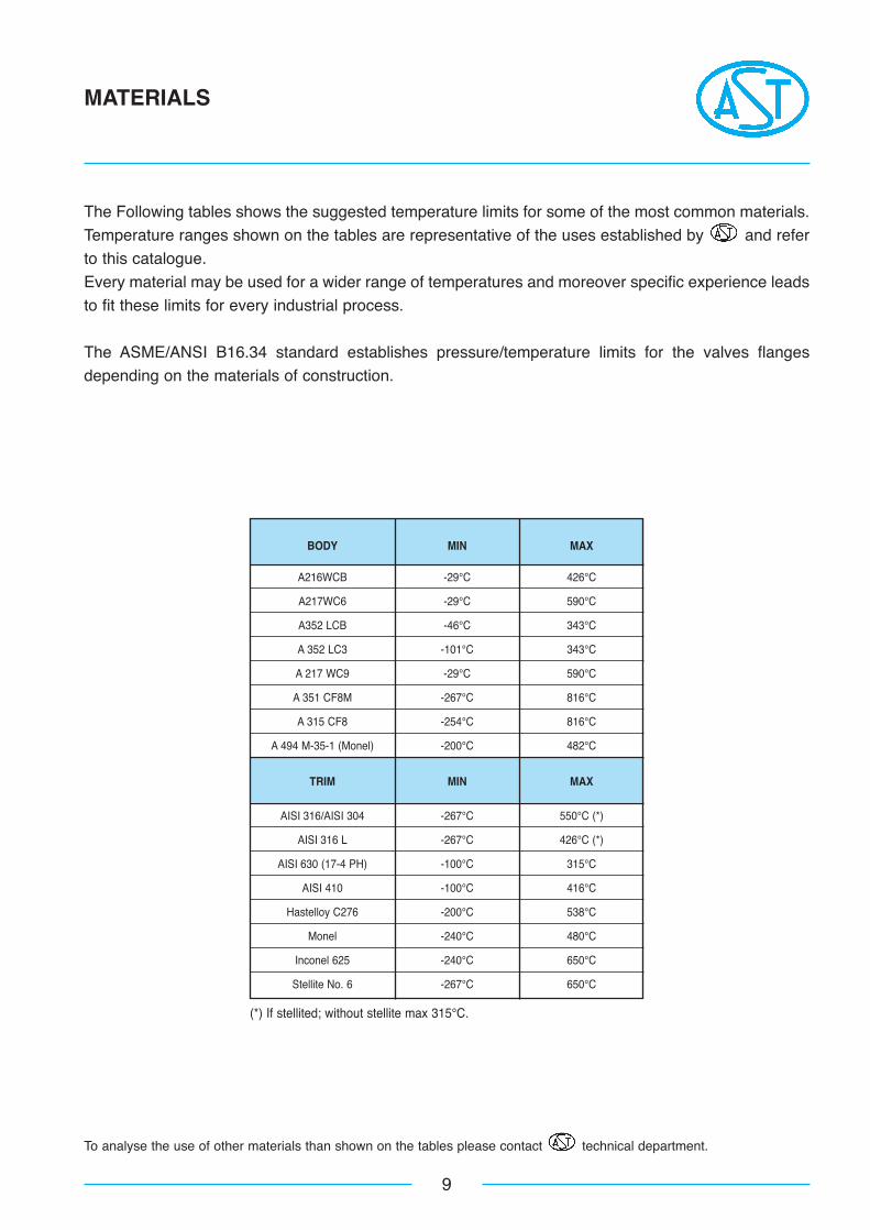
BODY MIN MAX
A216WCB -29°C 426°C
A217WC6 -29°C 590°C
A352 LCB -46°C 343°C
A 352 LC3 -101°C 343°C
A 217 WC9 -29°C 590°C
A 351 CF8M -267°C 816°C
A 315 CF8 -254°C 816°C
A 494 M-35-1 (Monel) -200°C 482°C
TRIM MIN MAX
AISI 316/AISI 304 -267°C 550°C (*)
AISI 316 L -267°C 426°C (*)
AISI 630 (17-4 PH) -100°C 315°C
AISI 410 -100°C 416°C
Hastelloy C276 -200°C 538°C
Monel -240°C 480°C
Inconel 625 -240°C 650°C
Stellite No. 6 -267°C 650°C
9
MATERIALS
The Following tables shows the suggested temperature limits for some of the most common materials.
Temperature ranges shown on the tables are representative of the uses established by and refer
to this catalogue.
Every material may be used for a wider range of temperatures and moreover specific experience leads
to fit these limits for every industrial process.
The ASME/ANSI B16.34 standard establishes pressure/temperature limits for the valves flanges
depending on the materials of construction.
To analyse the use of other materials than shown on the tables please contact technical department.
(*) If stellited; without stellite max 315°C.
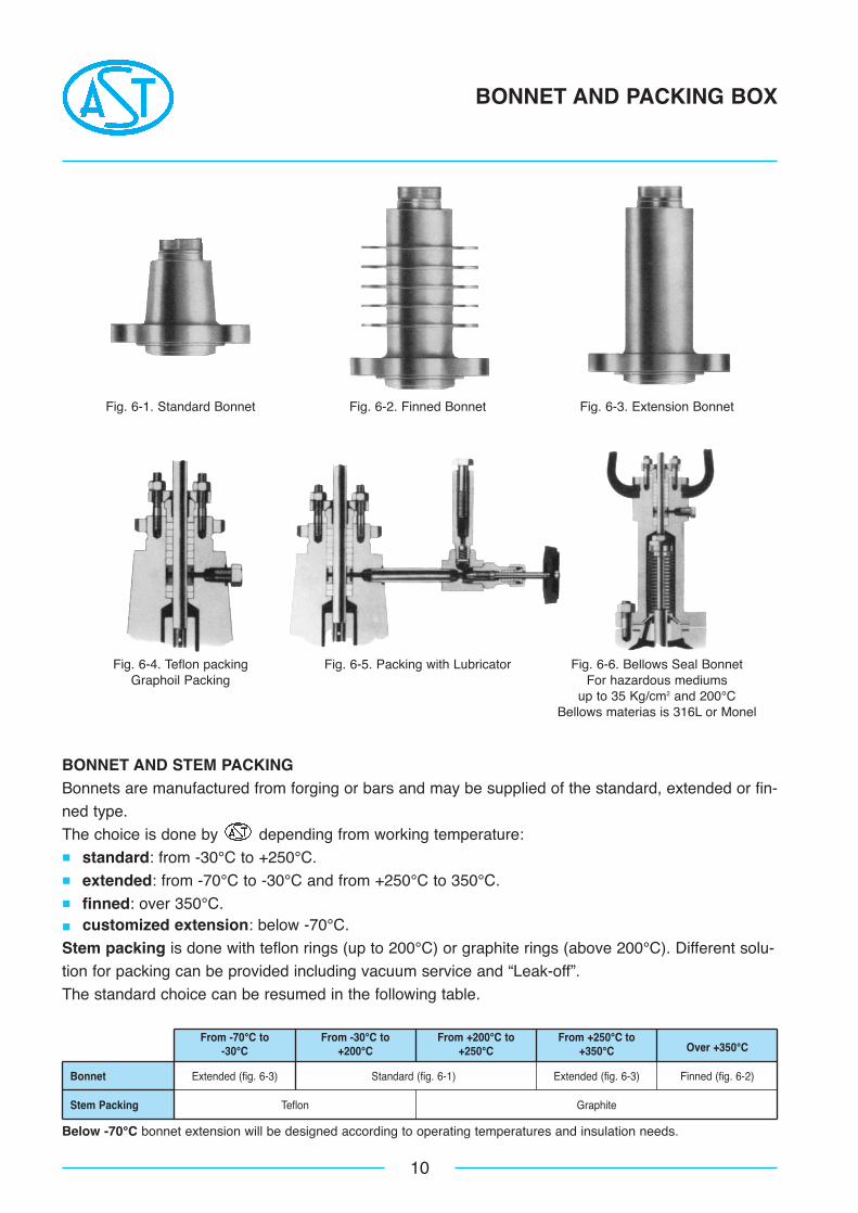
From -70°C to From -30°C to From +200°C to From +250°C toOver +350°C-30°C +200°C +250°C +350°C
Bonnet Extended (fig. 6-3) Standard (fig. 6-1) Extended (fig. 6-3) Finned (fig. 6-2)
Stem Packing Teflon Graphite
10
BONNET AND PACKING BOX
BONNET AND STEM PACKINGBonnets are manufactured from forging or bars and may be supplied of the standard, extended or fin-
ned type.
The choice is done by depending from working temperature:� standard: from -30°C to +250°C.� extended: from -70°C to -30°C and from +250°C to 350°C.� finned: over 350°C.� customized extension: below -70°C.
Stem packing is done with teflon rings (up to 200°C) or graphite rings (above 200°C). Different solu-
tion for packing can be provided including vacuum service and “Leak-off”.
The standard choice can be resumed in the following table.
Below -70°C bonnet extension will be designed according to operating temperatures and insulation needs.
Fig. 6-1. Standard Bonnet Fig. 6-2. Finned Bonnet Fig. 6-3. Extension Bonnet
Fig. 6-4. Teflon packing Fig. 6-5. Packing with Lubricator Fig. 6-6. Bellows Seal BonnetGraphoil Packing For hazardous mediums
up to 35 Kg/cm2 and 200°CBellows materias is 316L or Monel
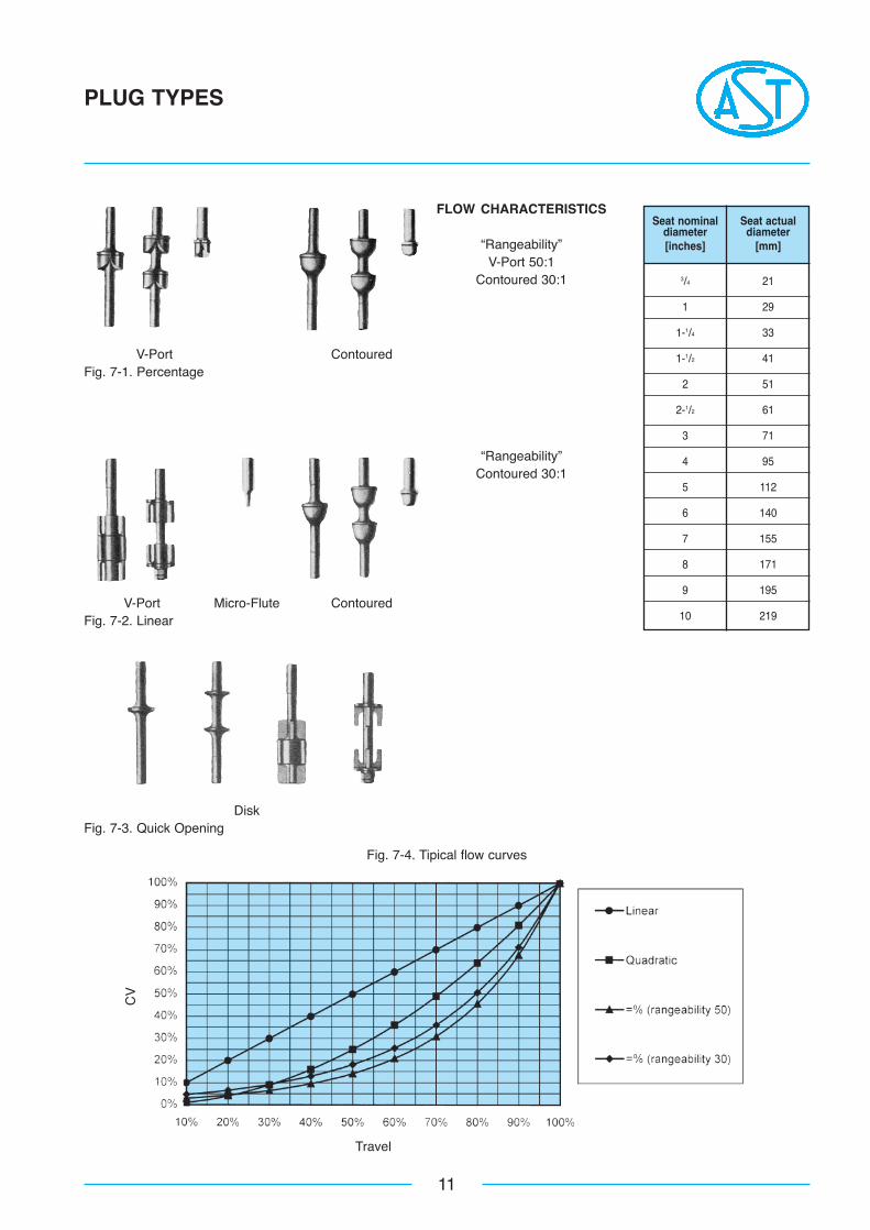
Seat nominal Seat actualdiameter diameter[inches] [mm]
11
PLUG TYPES
V-Port ContouredFig. 7-1. Percentage
FLOW CHARACTERISTICS
“Rangeability”V-Port 50:1
Contoured 30:1
V-Port Micro-Flute ContouredFig. 7-2. Linear
“Rangeability”Contoured 30:1
DiskFig. 7-3. Quick Opening
Fig. 7-4. Tipical flow curves
Travel
CV
3/4 21
1 29
1-1/4 33
1-1/2 41
2 51
2-1/2 61
3 71
4 95
5 112
6 140
7 155
8 171
9 195
10 219
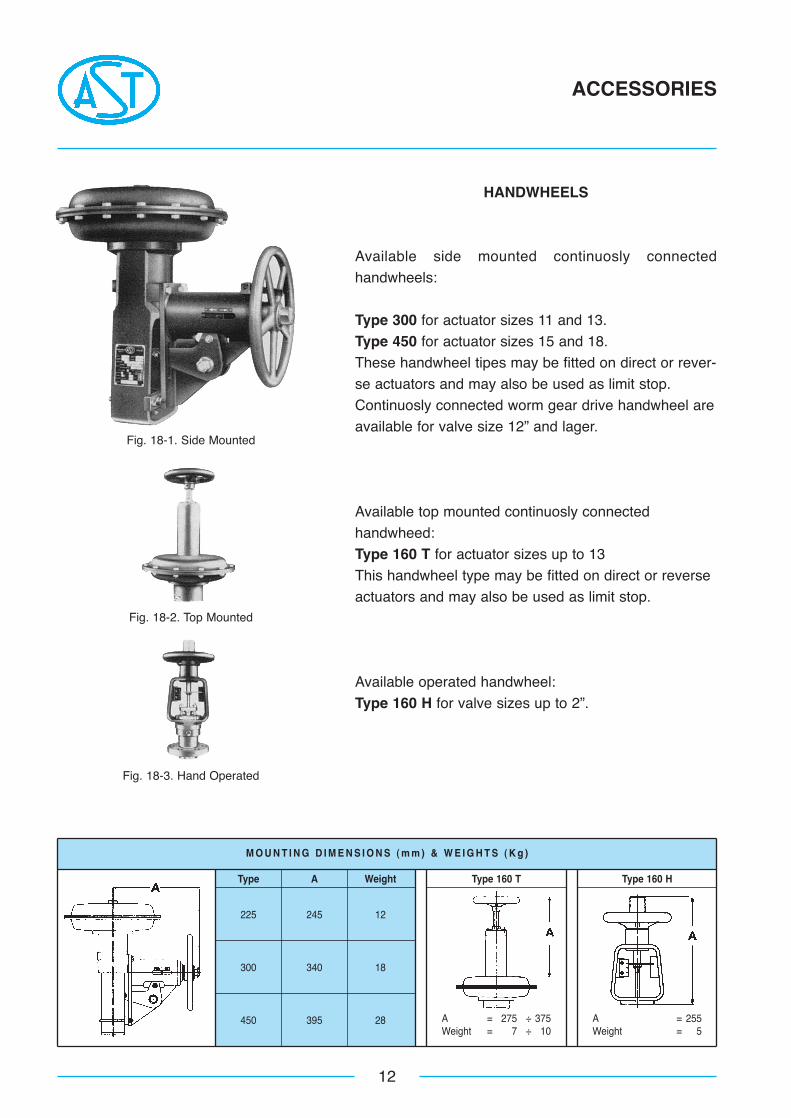
M O U N T I N G D I M E N S I O N S ( m m ) & W E I G H T S ( K g )
Type A Weight
225 245 12
300 340 18
450 395 28
Type 160 T
A = 275 ÷ 375Weight = 7 ÷ 10
A = 255Weight = 5
Type 160 H
12
ACCESSORIES
HANDWHEELS
Available side mounted continuosly connected
handwheels:
Type 300 for actuator sizes 11 and 13.
Type 450 for actuator sizes 15 and 18.
These handwheel tipes may be fitted on direct or rever-
se actuators and may also be used as limit stop.
Continuosly connected worm gear drive handwheel are
available for valve size 12” and lager.
Available top mounted continuosly connected
handwheed:
Type 160 T for actuator sizes up to 13
This handwheel type may be fitted on direct or reverse
actuators and may also be used as limit stop.
Available operated handwheel:
Type 160 H for valve sizes up to 2”.
Fig. 18-1. Side Mounted
Fig. 18-2. Top Mounted
Fig. 18-3. Hand Operated

A P P R O X I M AT E S H I P P I N G W E I G H T S ( K g )
1/2 - - - - - - 25 27 - 2
3/4 29 31 29 31 31 35 27 29 41 2
1 30 32 30 32 33 37 28 30 43 2
11/2 41 44 42 45 45 49 36 39 72 3
2 60 64 63 67 68 72 57 61 83 5
21/2 72 77 75 80 82 87 - - 94 5
3 93 99 100 106 110 118 86 92 129 8
4 135 142 143 150 155 165 120 127 165 12
6 262 272 280 294 300 318 245 255 257 15
8 430 450 455 480 480 510 415 435 - 20
10 670 710 718 768 758 813 - - - 20
12 - - 960 1020 1010 1080 - - - 28
14 - - 1380 1450 - - - - - 30
16 - - 1950 2040 - - - - - 36
13
SHIPPING WEIGHTS
VALVE TYPE
8100 8200 8300 8400 8700
ANSI ANSI ANSI ANSI ANSI
150-300 600 150-300 600 150-300 600 150-300 600 150-300-600
ValveSize
(inches)
Extrafor
FinnedBonnet
Remark: For ANSI 900, 1500, 2500 rating valves please contact representative.
Body nominal Seat nominalCV max
dimension dimension(=%V-port CV max Travel Standard
[inches] [inches]=% contoured (disk) [mm] actuator
linear)
14
TYPE 8100
3/43/4 6 9 13 9-9R
1 1 10 13 13 9-9R
1-1/2
1-1/4 16 2120 9L-9LR
1-1/2 23 30
2 2 39 52 25 11-11R
2-1/2 2-1/2 58 80 25 11-11R
3 3 82 105 40 13-13R
4 4 135 180 40 13-13R
6 6 295 400 50 15-15R
8 8 525 680 60 18-18R
10 10 750 1100 60 18-18R
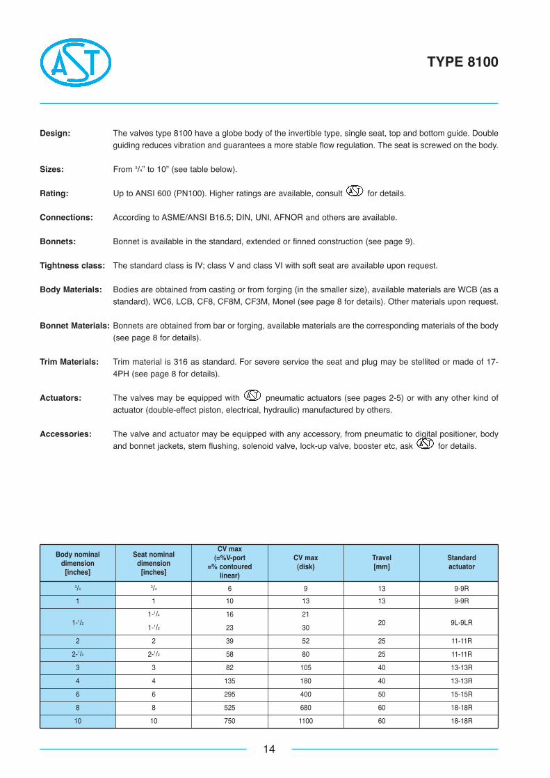
Design: The valves type 8100 have a globe body of the invertible type, single seat, top and bottom guide. Doubleguiding reduces vibration and guarantees a more stable flow regulation. The seat is screwed on the body.
Sizes: From 3/4” to 10” (see table below).
Rating: Up to ANSI 600 (PN100). Higher ratings are available, consult for details.
Connections: According to ASME/ANSI B16.5; DIN, UNI, AFNOR and others are available.
Bonnets: Bonnet is available in the standard, extended or finned construction (see page 9).
Tightness class: The standard class is IV; class V and class VI with soft seat are available upon request.
Body Materials: Bodies are obtained from casting or from forging (in the smaller size), available materials are WCB (as astandard), WC6, LCB, CF8, CF8M, CF3M, Monel (see page 8 for details). Other materials upon request.
Bonnet Materials: Bonnets are obtained from bar or forging, available materials are the corresponding materials of the body(see page 8 for details).
Trim Materials: Trim material is 316 as standard. For severe service the seat and plug may be stellited or made of 17-4PH (see page 8 for details).
Actuators: The valves may be equipped with pneumatic actuators (see pages 2-5) or with any other kind ofactuator (double-effect piston, electrical, hydraulic) manufactured by others.
Accessories: The valve and actuator may be equipped with any accessory, from pneumatic to digital positioner, bodyand bonnet jackets, stem flushing, solenoid valve, lock-up valve, booster etc, ask for details.
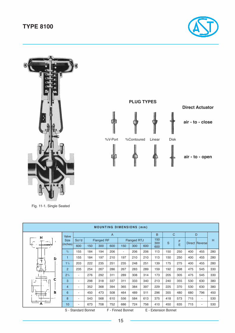
M O U N T I N G D I M E N S I O N S ( m m )
H
15
TYPE 8100
3/4 155 184 194 206 - 206 206 113 150 250 400 455 280
1 155 184 197 210 197 210 210 113 150 250 400 455 280
11/2 203 222 235 251 235 248 251 139 175 275 400 455 280
2 235 254 267 286 267 283 289 159 192 298 475 545 330
21/2 - 276 292 311 289 308 314 173 205 305 475 545 330
3 - 298 318 337 311 333 340 213 240 355 530 630 380
4 - 352 368 394 365 384 397 229 225 370 530 630 380
6 - 450 473 508 464 489 511 296 355 480 680 796 450
8 - 543 568 610 556 584 613 375 418 573 715 - 530
10 - 673 708 752 686 724 756 410 450 635 715 - 530
600 150 300 600 150 300 600
Scr’d Flanged RF Flanged RTJ 150300600
BAValveSize
(inches) S
C
FE Direct
D
Reverse
S - Standard Bonnet F - Finned Bonnet E - Extension Bonnet
Fig. 11-1. Single Seated
PLUG TYPESDirect Actuator
air - to - close
air - to - open
%V-Port %Contoured Linear Disk
Body nominal Seat nominalCV max
dimension dimension(=%V-port) CV max Travel Standard
[inches] [inches]=% contourded (disk) [mm] actuator
linear
16
TYPE 8200
3/43/4 9 11 13 9-9R
1 1 13 17 13 9-9R
1-1/2
1-1/4 20 2520 9L-9LR1-1/2 30 36
2 2 52 65 25 11-11R2-1/2 2-1/2 80 100 25 11-11R
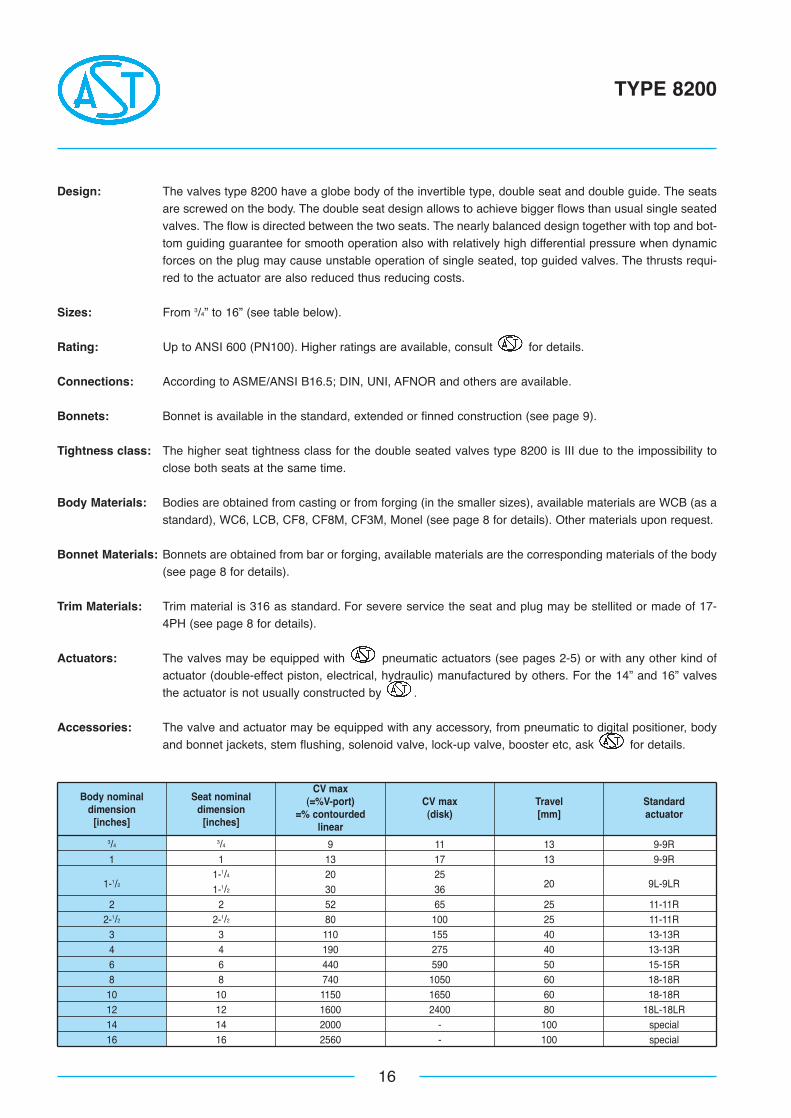
3 3 110 155 40 13-13R4 4 190 275 40 13-13R6 6 440 590 50 15-15R8 8 740 1050 60 18-18R10 10 1150 1650 60 18-18R12 12 1600 2400 80 18L-18LR14 14 2000 - 100 special16 16 2560 - 100 special
Design: The valves type 8200 have a globe body of the invertible type, double seat and double guide. The seatsare screwed on the body. The double seat design allows to achieve bigger flows than usual single seatedvalves. The flow is directed between the two seats. The nearly balanced design together with top and bot-tom guiding guarantee for smooth operation also with relatively high differential pressure when dynamicforces on the plug may cause unstable operation of single seated, top guided valves. The thrusts requi-red to the actuator are also reduced thus reducing costs.
Sizes: From 3/4” to 16” (see table below).
Rating: Up to ANSI 600 (PN100). Higher ratings are available, consult for details.
Connections: According to ASME/ANSI B16.5; DIN, UNI, AFNOR and others are available.
Bonnets: Bonnet is available in the standard, extended or finned construction (see page 9).
Tightness class: The higher seat tightness class for the double seated valves type 8200 is III due to the impossibility toclose both seats at the same time.
Body Materials: Bodies are obtained from casting or from forging (in the smaller sizes), available materials are WCB (as astandard), WC6, LCB, CF8, CF8M, CF3M, Monel (see page 8 for details). Other materials upon request.
Bonnet Materials: Bonnets are obtained from bar or forging, available materials are the corresponding materials of the body(see page 8 for details).
Trim Materials: Trim material is 316 as standard. For severe service the seat and plug may be stellited or made of 17-4PH (see page 8 for details).
Actuators: The valves may be equipped with pneumatic actuators (see pages 2-5) or with any other kind ofactuator (double-effect piston, electrical, hydraulic) manufactured by others. For the 14” and 16” valvesthe actuator is not usually constructed by .
Accessories: The valve and actuator may be equipped with any accessory, from pneumatic to digital positioner, bodyand bonnet jackets, stem flushing, solenoid valve, lock-up valve, booster etc, ask for details.
ValveSize
(inches)
M O U N T I N G D I M E N S I O N S ( m m )
17
TYPE 8200
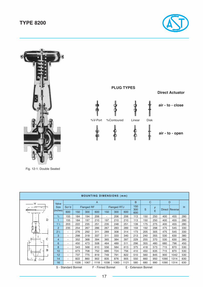
3/4 155 184 194 206 - 206 206 113 150 250 400 455 2801 155 184 197 210 197 210 210 113 150 250 400 455 280
11/2 203 222 235 251 235 248 251 139 175 275 400 455 2802 235 254 267 286 267 283 289 159 192 298 475 545 330
21/2 - 276 292 311 289 308 314 173 205 305 475 545 3303 - 298 318 337 311 333 340 213 240 355 530 630 3804 - 352 368 394 365 384 397 229 255 370 530 630 3806 - 450 473 508 464 489 511 296 355 480 680 796 4508 - 543 568 610 556 584 613 375 418 573 715 870 53010 - 673 708 752 686 724 756 410 450 635 715 870 53012 - 737 775 819 749 791 822 510 560 845 900 1042 53014 - 822 860 902 835 876 905 550 660 950 1090 1314 63016 - 1026 1067 1118 1038 1083 1121 580 680 990 1090 1314 630
600 150 300 600 150 300 600
Scr’d Flanged RF Flanged RTJ 150300600
BA
S
C
FE Direct
D
ReverseH
S - Standard Bonnet F - Finned Bonnet E - Extension Bonnet
Fig. 12-1. Double Seated
PLUG TYPESDirect Actuator
air - to - close
%V-Port %Contoured Linear Disk
air - to - open
Body nominal Seat nominal CV maxdimension dimension (linear V-port
Travel Standard
[inches] [inches] disk)[mm] actuator
18
TYPE 8300
3/43/4 6 13 9-9R
1 1 10 13 9-9R
1-1/2 1-1/2 23 20 9L-9LR
2 2 39 25 11-11R
2-1/2 2-1/2 58 25 11-11R
3 3 82 40 13-13R
4 4 135 40 13-13R
6 6 295 50 15-15R
8 8 525 60 18-18R
10 10 750 60 18-18R
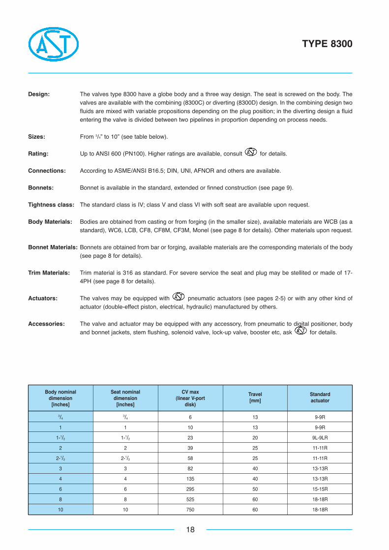
Design: The valves type 8300 have a globe body and a three way design. The seat is screwed on the body. Thevalves are available with the combining (8300C) or diverting (8300D) design. In the combining design twofluids are mixed with variable propositions depending on the plug position; in the diverting design a fluidentering the valve is divided between two pipelines in proportion depending on process needs.
Sizes: From 3/4” to 10” (see table below).
Rating: Up to ANSI 600 (PN100). Higher ratings are available, consult for details.
Connections: According to ASME/ANSI B16.5; DIN, UNI, AFNOR and others are available.
Bonnets: Bonnet is available in the standard, extended or finned construction (see page 9).
Tightness class: The standard class is IV; class V and class VI with soft seat are available upon request.
Body Materials: Bodies are obtained from casting or from forging (in the smaller size), available materials are WCB (as astandard), WC6, LCB, CF8, CF8M, CF3M, Monel (see page 8 for details). Other materials upon request.
Bonnet Materials: Bonnets are obtained from bar or forging, available materials are the corresponding materials of the body(see page 8 for details).
Trim Materials: Trim material is 316 as standard. For severe service the seat and plug may be stellited or made of 17-4PH (see page 8 for details).
Actuators: The valves may be equipped with pneumatic actuators (see pages 2-5) or with any other kind ofactuator (double-effect piston, electrical, hydraulic) manufactured by others.
Accessories: The valve and actuator may be equipped with any accessory, from pneumatic to digital positioner, bodyand bonnet jackets, stem flushing, solenoid valve, lock-up valve, booster etc, ask for details.
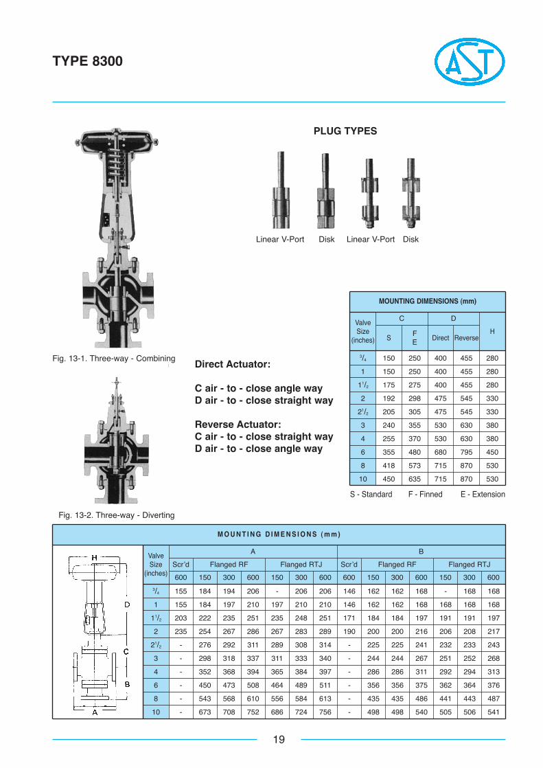
3/4 155 184 194 206 - 206 206 146 162 162 168 - 168 168
1 155 184 197 210 197 210 210 146 162 162 168 168 168 168
11/2 203 222 235 251 235 248 251 171 184 184 197 191 191 197
2 235 254 267 286 267 283 289 190 200 200 216 206 208 217
21/2 - 276 292 311 289 308 314 - 225 225 241 232 233 243
3 - 298 318 337 311 333 340 - 244 244 267 251 252 268
4 - 352 368 394 365 384 397 - 286 286 311 292 294 313
6 - 450 473 508 464 489 511 - 356 356 375 362 364 376
8 - 543 568 610 556 584 613 - 435 435 486 441 443 487
10 - 673 708 752 686 724 756 - 498 498 540 505 506 541
M O U N T I N G D I M E N S I O N S ( m m )
MOUNTING DIMENSIONS (mm)
3/4 150 250 400 455 280
1 150 250 400 455 280
11/2 175 275 400 455 280
2 192 298 475 545 330
21/2 205 305 475 545 330
3 240 355 530 630 380
4 255 370 530 630 380
6 355 480 680 795 450
8 418 573 715 870 530
10 450 635 715 870 530
ValveSize
(inches)
19
TYPE 8300
600 150 300 600 150 300 600 600 150 300 600 150 300 600
Scr’d Flanged RF Flanged RTJ Scr’d Flanged RF Flanged RTJ
A BValveSize
(inches)
S - Standard F - Finned E - Extension
C D
FE
S Direct ReverseH
Fig. 13-2. Three-way - Diverting
Fig. 13-1. Three-way - Combining
PLUG TYPES
Direct Actuator:
C air - to - close angle wayD air - to - close straight way
Reverse Actuator:C air - to - close straight wayD air - to - close angle way
Linear V-Port Disk Linear V-Port Disk
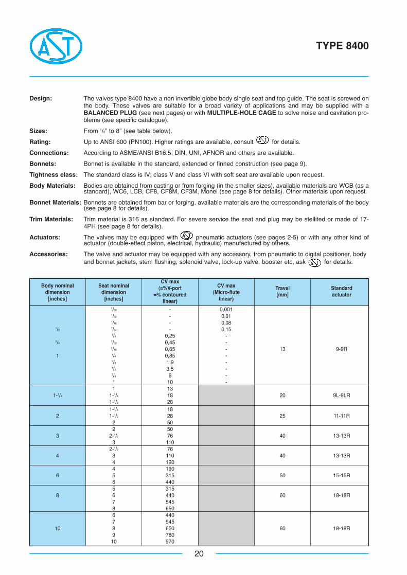
1/50 - 0,0011/32 - 0,011/16 - 0,08
1/27/64 - 0,151/8 0,25 -
3/41/32 0,45 -3/16 0,65 - 13 9-9R
1 1/4 0,85 -3/8 1,9 -1/2 3,5 -3/4 6 -1 10 -1 13
1-1/2 1-1/4 18 20 9L-9LR1-1/2 281-1/4 18
2 1-1/2 28 25 11-11R2 502 50
3 2-1/2 76 40 13-13R3 110
2-1/2 764 3 110 40 13-13R
4 1904 190
6 5 315 50 15-15R6 4405 315
8 6 440 60 18-18R7 5458 6506 4407 545
10 8 650 60 18-18R9 780
10 970
Body nominal Seat nominalCV max
CV maxdimension dimension
(=%V-port(Micro-flute
Travel Standard
[inches] [inches]=% contoured
linear)[mm] actuator
linear)
20
TYPE 8400
Design: The valves type 8400 have a non invertible globe body single seat and top guide. The seat is screwed onthe body. These valves are suitable for a broad variety of applications and may be supplied with aBALANCED PLUG (see next pages) or with MULTIPLE-HOLE CAGE to solve noise and cavitation pro-blems (see specific catalogue).
Sizes: From 1/2” to 8” (see table below).
Rating: Up to ANSI 600 (PN100). Higher ratings are available, consult for details.
Connections: According to ASME/ANSI B16.5; DIN, UNI, AFNOR and others are available.
Bonnets: Bonnet is available in the standard, extended or finned construction (see page 9).
Tightness class: The standard class is IV; class V and class VI with soft seat are available upon request.
Body Materials: Bodies are obtained from casting or from forging (in the smaller sizes), available materials are WCB (as astandard), WC6, LCB, CF8, CF8M, CF3M, Monel (see page 8 for details). Other materials upon request.
Bonnet Materials: Bonnets are obtained from bar or forging, available materials are the corresponding materials of the body(see page 8 for details).
Trim Materials: Trim material is 316 as standard. For severe service the seat and plug may be stellited or made of 17-4PH (see page 8 for details).
Actuators: The valves may be equipped with pneumatic actuators (see pages 2-5) or with any other kind ofactuator (double-effect piston, electrical, hydraulic) manufactured by others.
Accessories: The valve and actuator may be equipped with any accessory, from pneumatic to digital positioner, bodyand bonnet jackets, stem flushing, solenoid valve, lock-up valve, booster etc, ask for details.
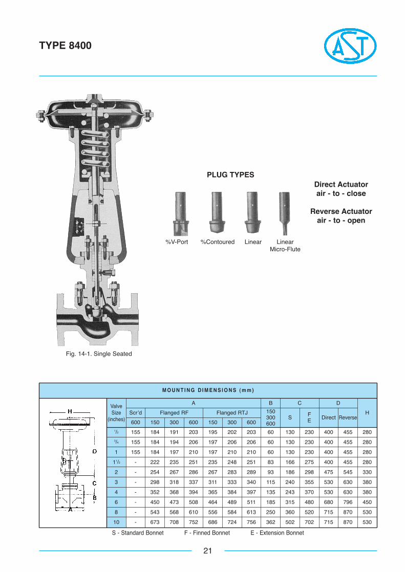
1/2 155 184 191 203 195 202 203 60 130 230 400 455 2803/4 155 184 194 206 197 206 206 60 130 230 400 455 280
1 155 184 197 210 197 210 210 60 130 230 400 455 280
11/2 - 222 235 251 235 248 251 83 166 275 400 455 280
2 - 254 267 286 267 283 289 93 186 298 475 545 330
3 - 298 318 337 311 333 340 115 240 355 530 630 380
4 - 352 368 394 365 384 397 135 243 370 530 630 380
6 - 450 473 508 464 489 511 185 315 480 680 796 450
8 - 543 568 610 556 584 613 250 360 520 715 870 530
10 - 673 708 752 686 724 756 362 502 702 715 870 530
M O U N T I N G D I M E N S I O N S ( m m )
21
TYPE 8400
600 150 300 600 150 300 600
Scr’d Flanged RF Flanged RTJ 150300600
BAValveSize
(inches) S
C
FE Direct
D
ReverseH
S - Standard Bonnet F - Finned Bonnet E - Extension Bonnet
Fig. 14-1. Single Seated
PLUG TYPESDirect Actuatorair - to - close
Reverse Actuatorair - to - open
%V-Port %Contoured Linear LinearMicro-Flute
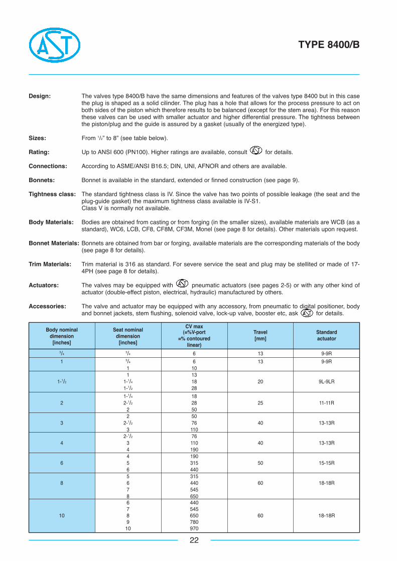
3/43/4 6 13 9-9R
1 3/4 6 13 9-9R1 101 13
1-1/2 1-1/4 18 20 9L-9LR1-1/2 28
1-1/4 182 2-1/2 28 25 11-11R
2 502 50
3 2-1/2 76 40 13-13R3 110
2-1/2 764 3 110 40 13-13R
4 1904 190
6 5 315 50 15-15R6 4405 315
8 6 440 60 18-18R7 5458 6506 4407 545
10 8 650 60 18-18R9 78010 970
Body nominal Seat nominalCV max
dimension dimension(=%V-port Travel Standard
[inches] [inches]=% contoured [mm] actuator
linear)
22
TYPE 8400/B
Design: The valves type 8400/B have the same dimensions and features of the valves type 8400 but in this casethe plug is shaped as a solid cilinder. The plug has a hole that allows for the process pressure to act onboth sides of the piston which therefore results to be balanced (except for the stem area). For this reasonthese valves can be used with smaller actuator and higher differential pressure. The tightness betweenthe piston/plug and the guide is assured by a gasket (usually of the energized type).
Sizes: From 1/2” to 8” (see table below).
Rating: Up to ANSI 600 (PN100). Higher ratings are available, consult for details.
Connections: According to ASME/ANSI B16.5; DIN, UNI, AFNOR and others are available.
Bonnets: Bonnet is available in the standard, extended or finned construction (see page 9).
Tightness class: The standard tightness class is IV. Since the valve has two points of possible leakage (the seat and theplug-guide gasket) the maximum tightness class available is IV-S1.Class V is normally not available.
Body Materials: Bodies are obtained from casting or from forging (in the smaller sizes), available materials are WCB (as astandard), WC6, LCB, CF8, CF8M, CF3M, Monel (see page 8 for details). Other materials upon request.
Bonnet Materials: Bonnets are obtained from bar or forging, available materials are the corresponding materials of the body(see page 8 for details).
Trim Materials: Trim material is 316 as standard. For severe service the seat and plug may be stellited or made of 17-4PH (see page 8 for details).
Actuators: The valves may be equipped with pneumatic actuators (see pages 2-5) or with any other kind ofactuator (double-effect piston, electrical, hydraulic) manufactured by others.
Accessories: The valve and actuator may be equipped with any accessory, from pneumatic to digital positioner, bodyand bonnet jackets, stem flushing, solenoid valve, lock-up valve, booster etc, ask for details.
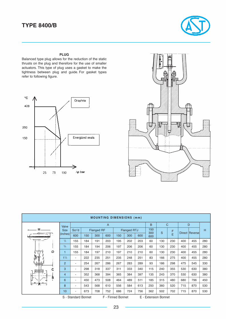
1/2 155 184 191 203 195 202 203 60 130 230 400 455 2803/4 155 184 194 206 197 206 206 60 130 230 400 455 280
1 155 184 197 210 197 210 210 60 130 230 400 455 280
11/2 - 222 235 251 235 248 251 83 166 275 400 455 280
2 - 254 267 286 267 283 289 93 186 298 475 545 330
3 - 298 318 337 311 333 340 115 240 355 530 630 380
4 - 352 368 394 365 384 397 135 243 370 530 630 380
6 - 450 473 508 464 489 511 185 315 480 680 796 450
8 - 543 568 610 556 584 613 250 360 520 715 870 530
10 - 673 708 752 686 724 756 362 502 702 715 870 530
M O U N T I N G D I M E N S I O N S ( m m )
23
TYPE 8400/B
600 150 300 600 150 300 600
Scr’d Flanged RF Flanged RTJ 150300600
BAValveSize
(inches) S
C
FE Direct
D
ReverseH
S - Standard Bonnet F - Finned Bonnet E - Extension Bonnet
PLUGBalanced type plug allows for the reduction of the staticthrusts on the plug and therefore for the use of smalleractuators. This type of plug uses a gasket to make thetightness between plug and guide. For gasket typesrefer to following figure.
Body nominal Seat nominal CV maxdimension dimension (=% contoured
Travel Standard
[inches] [inches] linear)[mm] actuator
1/8 0,43/16 1
3/41/4 1,63/8 3,2 20 9L
1 1/2 63/4 81 131 13
1-1/2 1-1/4 20 25 111-1/2 301-1/4 20
2 1-1/2 30 40 132 55
1-1/2 302-1/2 2 55 40 13
2-1/2 802 55
3 2-1/2 80 50 153 120
2-1/2 804 3 120 50 15
4 1954 195
6 5 340 60 186 425
24
TYPE 8700
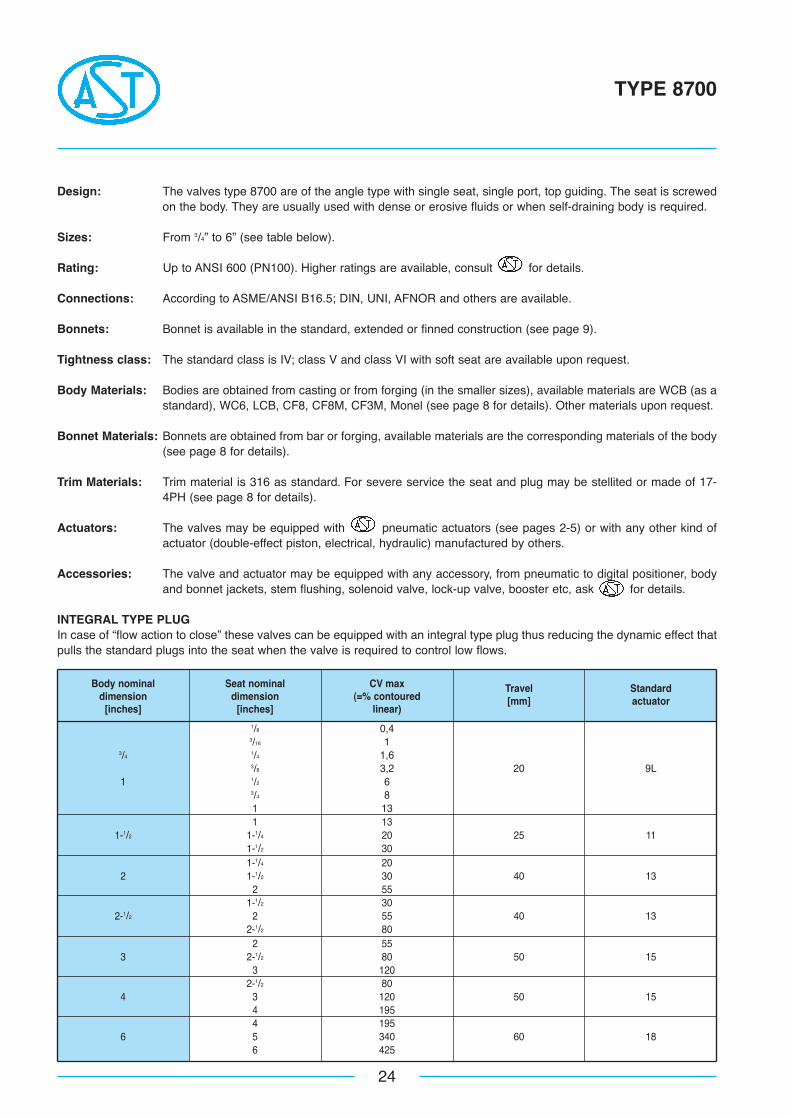
Design: The valves type 8700 are of the angle type with single seat, single port, top guiding. The seat is screwedon the body. They are usually used with dense or erosive fluids or when self-draining body is required.
Sizes: From 3/4” to 6” (see table below).
Rating: Up to ANSI 600 (PN100). Higher ratings are available, consult for details.
Connections: According to ASME/ANSI B16.5; DIN, UNI, AFNOR and others are available.
Bonnets: Bonnet is available in the standard, extended or finned construction (see page 9).
Tightness class: The standard class is IV; class V and class VI with soft seat are available upon request.
Body Materials: Bodies are obtained from casting or from forging (in the smaller sizes), available materials are WCB (as astandard), WC6, LCB, CF8, CF8M, CF3M, Monel (see page 8 for details). Other materials upon request.
Bonnet Materials: Bonnets are obtained from bar or forging, available materials are the corresponding materials of the body(see page 8 for details).
Trim Materials: Trim material is 316 as standard. For severe service the seat and plug may be stellited or made of 17-4PH (see page 8 for details).
Actuators: The valves may be equipped with pneumatic actuators (see pages 2-5) or with any other kind ofactuator (double-effect piston, electrical, hydraulic) manufactured by others.
Accessories: The valve and actuator may be equipped with any accessory, from pneumatic to digital positioner, bodyand bonnet jackets, stem flushing, solenoid valve, lock-up valve, booster etc, ask for details.
INTEGRAL TYPE PLUGIn case of “flow action to close” these valves can be equipped with an integral type plug thus reducing the dynamic effect thatpulls the standard plugs into the seat when the valve is required to control low flows.
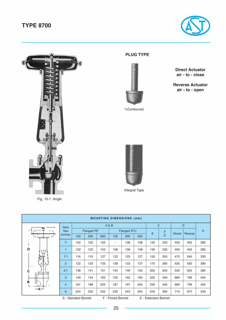
3/4 102 102 102 - 108 108 130 230 400 455 280
1 102 102 102 108 108 108 130 230 400 455 280
11/2 116 119 127 122 125 127 150 250 475 545 330
2 122 125 135 128 133 137 175 280 530 630 380
21/2 138 141 151 144 149 153 200 305 530 630 380
3 149 154 163 155 162 165 225 340 680 796 450
4 181 189 202 187 197 204 230 345 680 796 450
6 224 235 252 230 243 254 255 380 715 870 530
M O U N T I N G D I M E N S I O N S ( m m )
25
TYPE 8700
S - Standard Bonnet F - Finned Bonnet E - Extension Bonnet
150 300 600 150 300 600
Flanged RF Flanged RTJ
A & BValveSize
(inches) S
C
FE Direct
D
ReverseH
Fig. 15-1. Angle
PLUG TYPE
%Contoured
Direct Actuatorair - to - close
Reverse Actuatorair - to - open
Integral Type
26
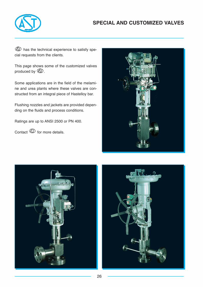
SPECIAL AND CUSTOMIZED VALVES
has the technical experience to satisfy spe-
cial requests from the clients.
This page shows some of the customized valves
produced by .
Some applications are in the field of the melami-
ne and urea plants where these valves are con-
structed from an integral piece of Hastelloy bar.
Flushing nozzles and jackets are provided depen-
ding on the fluids and process conditions.
Ratings are up to ANSI 2500 or PN 400.
Contact for more details.
27

Catalogue N. CV-02-2001
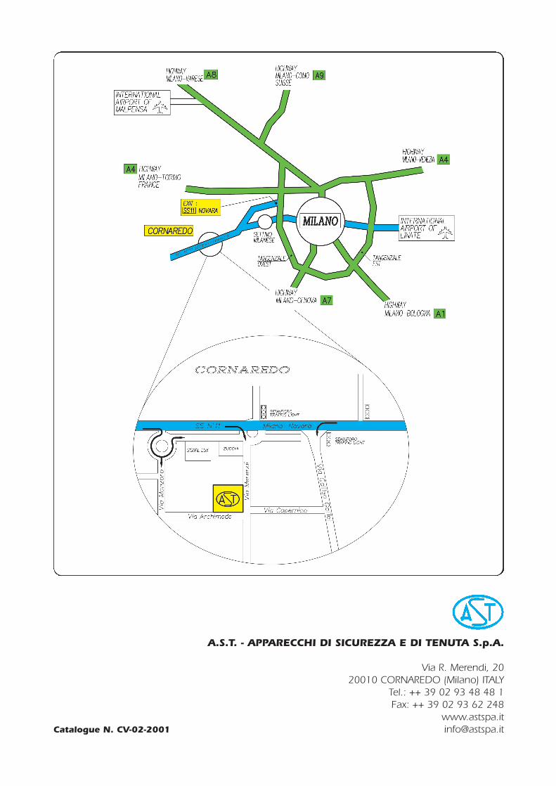
A.S.T. - APPARECCHI DI SICUREZZA E DI TENUTA S.p.A.
Via R. Merendi, 2020010 CORNAREDO (Milano) ITALY
Tel.: ++ 39 02 93 48 48 1Fax: ++ 39 02 93 62 248


![Dnevni avaz [broj 6871, 26.9.2014]](https://img.pdfslide.tips/doc/110x75/577cc4be1a28aba7119a47e2/dnevni-avaz-broj-6871-2692014.jpg)