Embed Size (px)
Citation preview
User Manual
CE-250Read this guide thoroughly and follow the installation and operationprocedures carefully in order to prevent any damage to the units and/orany devices that connect to them.
This package contains:
� 1 CE-250L KVM Extender Local Unit
� 1 CE-250R KVM Extender Remote Unit
� 1 CS Custom KVM Cable
� 2 Power Adapters
� 1 User Manual
� 1 Quick Start Guide
If anything is damaged or missing, contact your dealer.
© Copyright 2002 ATEN® International Co., Ltd.Manual Part No. PAPE - 1221-100Printed in Taiwan 12/2002
CONSOLE
REMOTE I /O
AC 9V
C
O
N
S
O
LE
R
EM
O
TE
I /
O
AC
9V
2002-12-16
Note: This equipment has been tested and found to comply withthe limits for a Class B digital device, pursuant to Part 15 of the FCCRules. These limits are designed to provide reasonable protectionagainst harmful interference in a residential installation. Thisequipment generates, uses and can radiate radio frequency energy,and if not installed and used in accordance with the instructionmanual, may cause interference to radio communications.However, there is no guarantee that interference will not occur in aparticular installation. If this equipment does cause harmfulinterference to radio or television reception, which can bedetermined by turning the equipment off and on, the user isencouraged to try to correct the interference by one or more of thefollowing measures:
� Reorient or relocate the receiving antenna;
� Increase the separation between the equipment and receiver;
� Connect the equipment into an outlet on a circuit different fromthat which the receiver is connected;
� Consult the dealer or an experienced radio/television technicianfor help.
2002-12-16
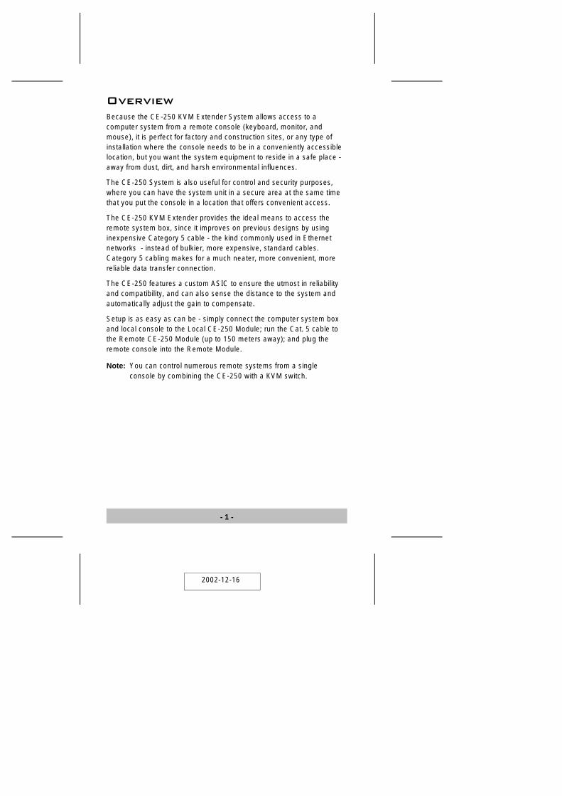
OverviewBecause the CE-250 KVM Extender System allows access to acomputer system from a remote console (keyboard, monitor, andmouse), it is perfect for factory and construction sites, or any type ofinstallation where the console needs to be in a conveniently accessiblelocation, but you want the system equipment to reside in a safe place -away from dust, dirt, and harsh environmental influences.
The CE-250 System is also useful for control and security purposes,where you can have the system unit in a secure area at the same timethat you put the console in a location that offers convenient access.
The CE-250 KVM Extender provides the ideal means to access theremote system box, since it improves on previous designs by usinginexpensive Category 5 cable - the kind commonly used in Ethernetnetworks - instead of bulkier, more expensive, standard cables.Category 5 cabling makes for a much neater, more convenient, morereliable data transfer connection.
The CE-250 features a custom ASIC to ensure the utmost in reliabilityand compatibility, and can also sense the distance to the system andautomatically adjust the gain to compensate.
Setup is as easy as can be - simply connect the computer system boxand local console to the Local CE-250 Module; run the Cat. 5 cable tothe Remote CE-250 Module (up to 150 meters away); and plug theremote console into the Remote Module.
Note: You can control numerous remote systems from a singleconsole by combining the CE-250 with a KVM switch.
- 1 -
2002-12-16
Features
� Built-in ASIC for Greater Reliability and Compatibility
� Category 5 Ethernet Cable to Connect the Local and Remote Units -Up To 150 m Apart
� Dual Console Operation - Control Your System From Both the Localand Remote PS/2 Keyboard, Mouse, and Monitor Consoles
� Push Button Selection of the Active Console
� High Resolution Video - Up To 1280 x 1024
� Supports VGA, SVGA, and Multisync Monitors
� Local Monitor Supports DDC; DDC2; DDC2B
� Automatic Gain Control - Automatically Adjusts Signal Strength toCompensate for Distance
System RequirementsConsoles
� A VGA, SVGA, or Multisync monitor capable of the highestresolution that you will be using on any computer in the installation
� A PS/2 style keyboard
� A PS/2 style mouse
Note: 1. If you connect a DDC type monitor to the Local unit, themonitor that connects to the Remote unit must be able tosupport the highest video resolution that the DDC monitorcan provide.
2. You must use the same brand and model of mouse on boththe local and remote units.
- 2 -
2002-12-16
Computers
The following equipment must be installed on each computer that is tobe connected to the system:
� With PS/2 Type Connectors:
� A VGA, SVGA or Multisync card.
� A 6-pin mini-DIN mouse port
� A 6-pin mini-DIN keyboard port
� With AT Type Connectors:
� A VGA, SVGA or Multisync card.
� A DB-9 (standard serial), mouse port plus mouse adapter (part #2A-105).*
� A 5-pin DIN (standard AT), keyboard port plus keyboard adapter(part # 2A-106).*
* Not included - requires separate purchase.
Cables� Although it is possible to use standard KVM cables to link computers
with PS/2 type keyboard and mouse ports to the CE-250L, foroptimum signal integrity and to simplify the layout, we stronglyrecommend that you use the high quality CS Custom KVM Cablethat is provided with this package.
� It is not possible to use standard KVM cables to link computers withAT type keyboard and mouse ports to the CE-250L. For thosecomputers, CS Custom KVM Cables must be used.
� Category 5 cable is the minimum required to connect the local andremote CE-250 units. Cable of a lesser standard will result indegrading the video signal. For best performance, we stronglyrecommend Category 5 cable.
- 3 -
2002-12-16
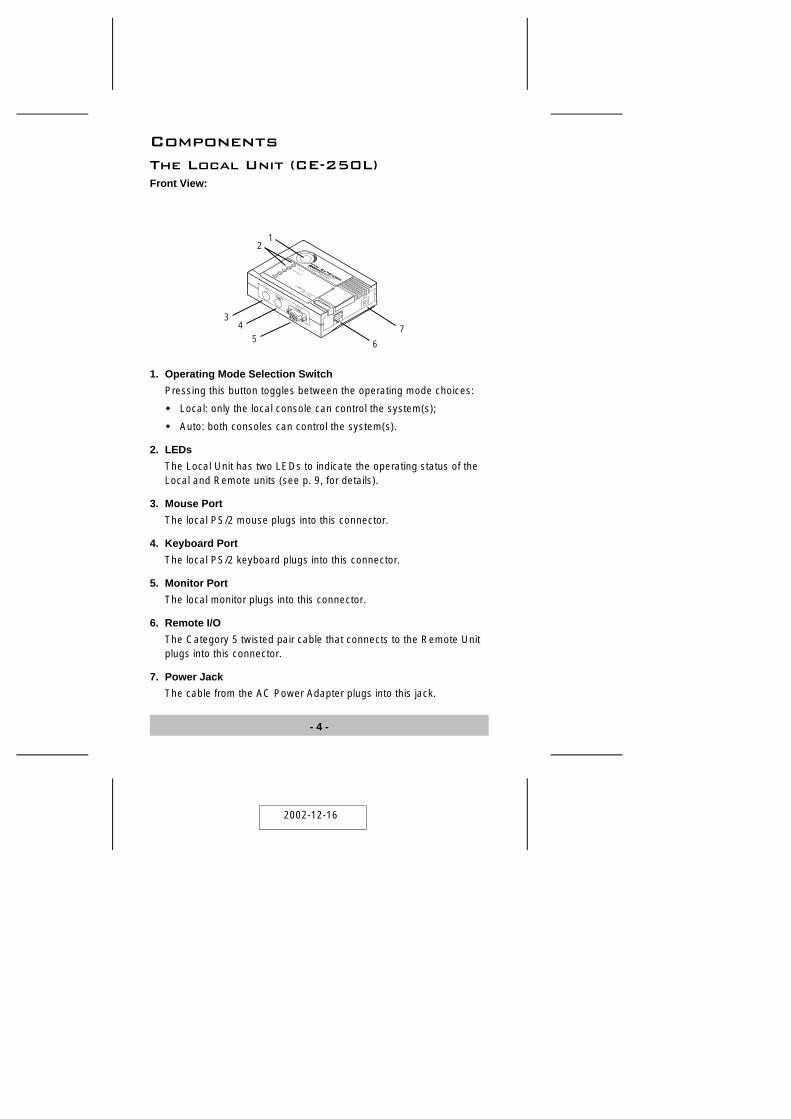
ComponentsThe Local Unit (CE-250L)Front View:
1. Operating Mode Selection Switch
Pressing this button toggles between the operating mode choices:
� Local: only the local console can control the system(s);
� Auto: both consoles can control the system(s).
2. LEDs
The Local Unit has two LEDs to indicate the operating status of theLocal and Remote units (see p. 9, for details).
3. Mouse Port
The local PS/2 mouse plugs into this connector.
4. Keyboard Port
The local PS/2 keyboard plugs into this connector.
5. Monitor Port
The local monitor plugs into this connector.
6. Remote I/O
The Category 5 twisted pair cable that connects to the Remote Unitplugs into this connector.
7. Power Jack
The cable from the AC Power Adapter plugs into this jack.
- 4 -
12
3
6
45
7
C
O
N
S
O
LE
R
EM
O
TE
I /
O
AC
9V
2002-12-16
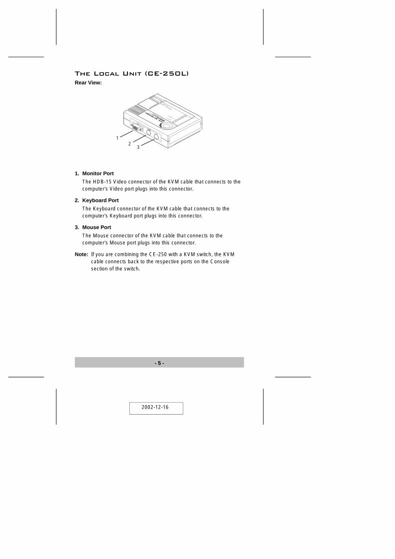
The Local Unit (CE-250L)Rear View:
1. Monitor Port
The HDB-15 Video connector of the KVM cable that connects to thecomputer’s Video port plugs into this connector.
2. Keyboard Port
The Keyboard connector of the KVM cable that connects to thecomputer’s Keyboard port plugs into this connector.
3. Mouse Port
The Mouse connector of the KVM cable that connects to thecomputer’s Mouse port plugs into this connector.
Note: If you are combining the CE-250 with a KVM switch, the KVMcable connects back to the respective ports on the Consolesection of the switch.
CP
U
12
3
- 5 -
2002-12-16
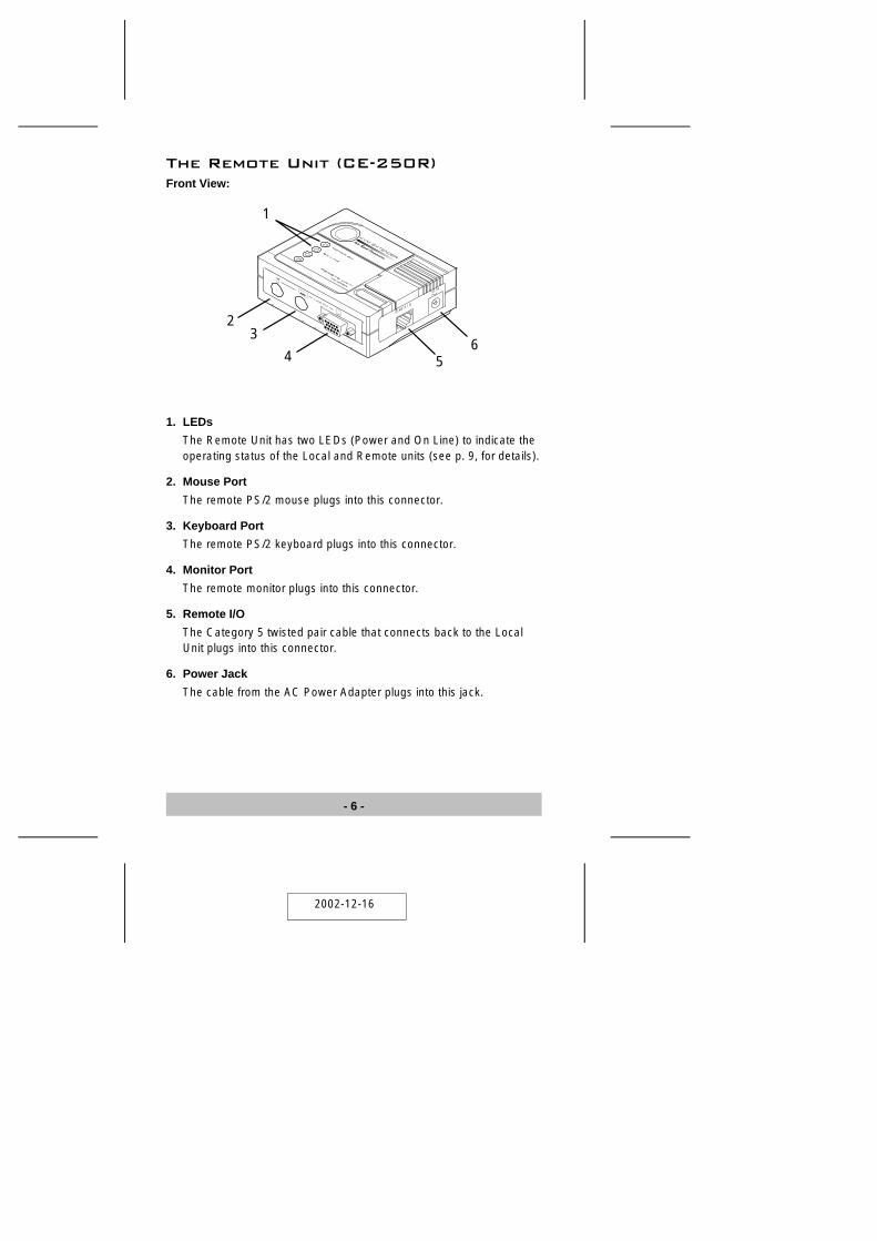
The Remote Unit (CE-250R)Front View:
1. LEDs
The Remote Unit has two LEDs (Power and On Line) to indicate theoperating status of the Local and Remote units (see p. 9, for details).
2. Mouse Port
The remote PS/2 mouse plugs into this connector.
3. Keyboard Port
The remote PS/2 keyboard plugs into this connector.
4. Monitor Port
The remote monitor plugs into this connector.
5. Remote I/O
The Category 5 twisted pair cable that connects back to the LocalUnit plugs into this connector.
6. Power Jack
The cable from the AC Power Adapter plugs into this jack.
CONSOLE
REMOTE I /O
AC 9V
1
23
4 56
- 6 -
2002-12-16
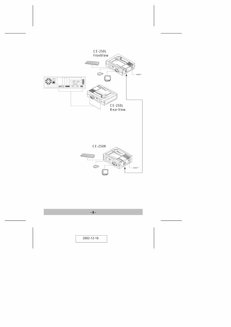
InstallationSetting up the KVM Extender System is simply a matter of plugging inthe cables:
1. Make sure that all the equipment to be connected up is powered Off.
2. Plug the cables from the local console devices (mouse, keyboard,monitor), into their ports on the Console side of the Local Unit(CE-250L).
3. Plug the appropriate connectors on the KVM cable supplied with thisunit into the CPU side of the CE-250L. Each connector is markedwith an appropriate icon to indicate which it is.
Note: The female monitor connector is the one that plugs into theCE-250L.
4. Plug the connectors on the other end of the cable into theappropriate ports on the computer system (or Console section of theKVM switch - if you are using one). Each connector is marked withan appropriate icon to indicate which it is.
5. Plug either end of the Category 5 twisted pair cable into theCE-250L’s Remote I/O port.
6. Plug one of the power adapters (supplied with this package) into anAC source; plug the adapter’s power cable into the CE-250L’sPower Jack
7. Plug the other end of the Category 5 twisted pair cable into the I/Oport of the Remote Unit (CE-250R).
8. Plug the cables from the remote console devices (mouse, keyboard,monitor), into their ports on the Console side of the CE-250R.
9. Plug the second power adapter (supplied with this package) into anAC source; plug the adapter’s power cable into the CE-250R’sPower Jack.
- 7 -
2002-12-16
- 8 -
CE-250LRear View
CE-250LFrontView
CE-250R
C
O
N
S
O
LE
R
EM
O
TE
I /
O
AC
9V
CP
U
CONSOLE
REMOTE I /O
AC 9V
2002-12-16
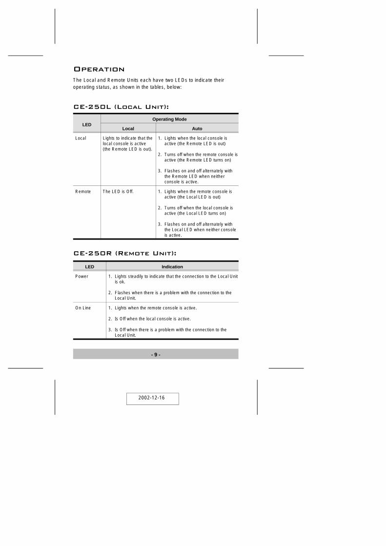
OperationThe Local and Remote Units each have two LEDs to indicate theiroperating status, as shown in the tables, below:
CE-250L (Local Unit):
LEDOperating Mode
Local Auto
Local Lights to indicate that thelocal console is active(the Remote LED is out).
1. Lights when the local console isactive (the Remote LED is out)
2. Turns off when the remote console isactive (the Remote LED turns on)
3. Flashes on and off alternately withthe Remote LED when neither console is active.
Remote The LED is Off. 1. Lights when the remote console isactive (the Local LED is out)
2. Turns off when the local console isactive (the Local LED turns on)
3. Flashes on and off alternately withthe Local LED when neither console is active.
CE-250R (Remote Unit):
LED Indication
Power 1. Lights steadily to indicate that the connection to the Local Unitis ok.
2. Flashes when there is a problem with the connection to theLocal Unit.
On Line 1. Lights when the remote console is active.
2. Is Off when the local console is active.
3. Is Off when there is a problem with the connection to theLocal Unit.
- 9 -
2002-12-16
Troubleshooting
Symptom Action
No Video Make sure that all cables are securely plugged into theirsockets.
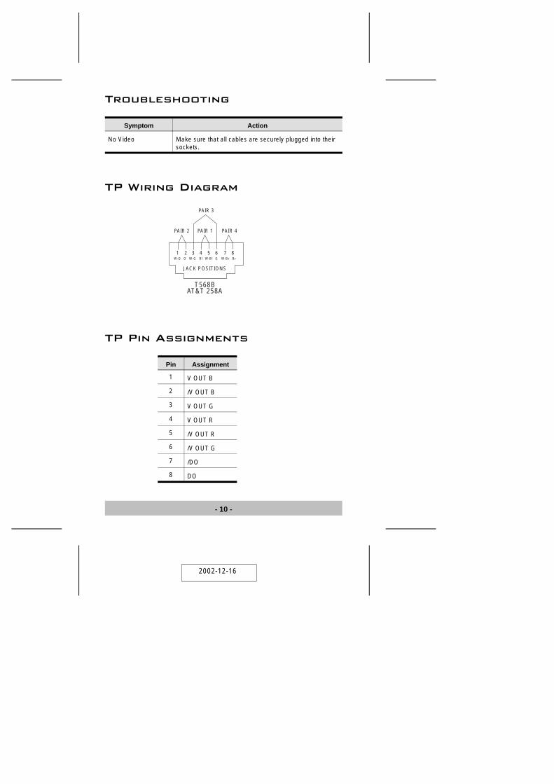
TP Wiring Diagram
TP Pin Assignments
Pin Assignment
1 V OUT B
2 /V OUT B
3 V OUT G
4 V OUT R
5 /V OUT R
6 /V OUT G
7 /DO
8 DO
- 10 -
JACK POSITIONS
PAIR 2 PAIR 1
PAIR 3
PAIR 4
T568BAT&T 258A
W-O W-GO G W-Br BrBl W-Bl1 2 3 4 5 6 7 8
2002-12-16
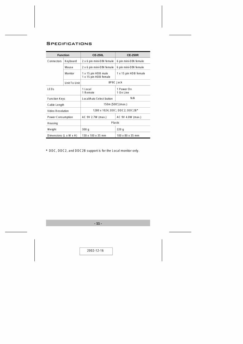
Specifications
Function CE-250L CE-250R
Connectors Keyboard 2 x 6 pin mini-DIN female 6 pin mini-DIN female
Mouse 2 x 6 pin mini-DIN female 6 pin mini-DIN female
Monitor 1 x 15 pin HDB male1 x 15 pin HDB female
1 x 15 pin HDB female
Unit To Unit 8P8C Jack
LEDs 1 Local1 Remote
1 Power On1 On Line
Function Keys Local/Auto Select button N/A
Cable Length 150m [500’] (max.)
Video Resolution 1280 x 1024; DDC; DDC2; DDC2B*
Power Consumption AC 9V 2.7W (max.) AC 9V 4.0W (max.)
Housing Plastic
Weight 300 g 220 g
Dimensions (L x W x H) 130 x 100 x 35 mm 100 x 80 x 35 mm
* DDC, DDC2, and DDC2B support is for the Local monitor only.
- 11 -
2002-12-16
Limited Warranty
IN NO EVENT SHALL THE DIRECT VENDOR’S LIABILITY EXCEEDTHE PRICE PAID FOR THE PRODUCT FROM DIRECT, INDIRECT,SPECIAL, INCIDENTAL, OR CONSEQUENTIAL DAMAGESRESULTING FROM THE USE OF THE PRODUCT, DISK, OR ITSDOCUMENTATION.
The direct vendor makes no warranty or representation, expressed,implied, or statutory with respect to the contents or use of thisdocumentation, and especially disclaims its quality, performance,merchantability, or fitness for any particular purpose.
The direct vendor also reserves the right to revise or update the deviceor documentation without obligation to notify any individual or entity ofsuch revisions, or update. For further inquiries, please contact yourdirect vendor.
- 12 -
2002-12-16

Notes:
- 13 -
2002-12-16
Notes:
- 14 -
2002-12-16


![PAIR´ [Modo de compatibilidad]](https://img.pdfslide.tips/doc/110x75/55cf900d550346703ba2bb3a/pair-modo-de-compatibilidad.jpg)