Embed Size (px)
Citation preview
CS 457 – Lecture 20 Transport Layer: UDP and TCP
Fall 2011
Topics • Principles underlying transport-layer
services – Demultiplexing – Detecting corruption – Reliable delivery – Flow control
• Transport-layer protocols – User Datagram Protocol (UDP) – Transmission Control Protocol (TCP)
Role of Transport Layer • Application layer
– Communication between networked applications – Protocols: HTTP, FTP, NNTP, and many others
• Transport layer – Communication between processes (e.g.,
socket) – Relies on network layer and serves the
application layer – Protocols: TCP and UDP
• Network layer – Communication between nodes – Protocols: IP
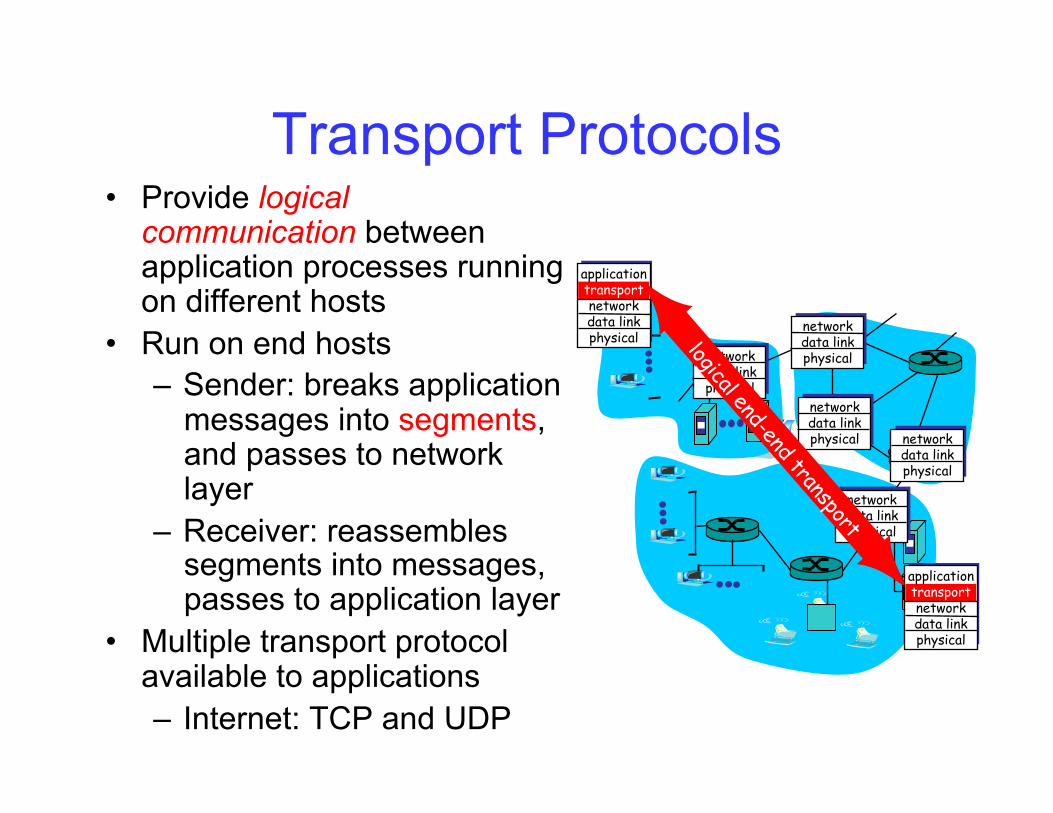
Transport Protocols • Provide logical
communication between application processes running on different hosts
• Run on end hosts – Sender: breaks application
messages into segments, and passes to network layer
– Receiver: reassembles segments into messages, passes to application layer
• Multiple transport protocol available to applications – Internet: TCP and UDP
application transport network data link physical
application transport network data link physical
network data link physical
network data link physical
network data link physical
network data link physical network
data link physical
Internet Transport Protocols • Datagram messaging service (UDP)
– No-frills extension of “best-effort” IP – Just send the data – each send is a message
• Reliable, streaming, in-order delivery (TCP) – Connection set-up – Discarding of corrupted packets – Retransmission of lost packets – Flow control – Congestion control (next lecture)
• Services not available – Delay guarantees – Bandwidth guarantees
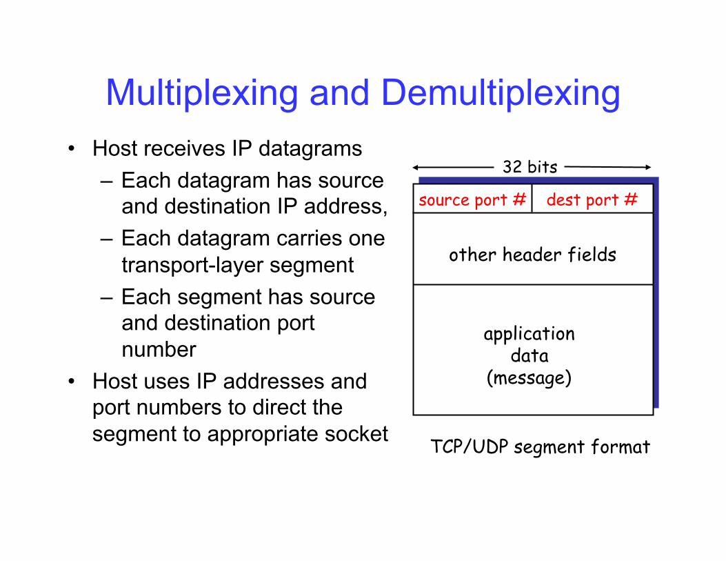
Multiplexing and Demultiplexing • Host receives IP datagrams
– Each datagram has source and destination IP address,
– Each datagram carries one transport-layer segment
– Each segment has source and destination port number
• Host uses IP addresses and port numbers to direct the segment to appropriate socket
source port # dest port # 32 bits
application data
(message)
other header fields
TCP/UDP segment format
User Datagram Protocol (UDP)
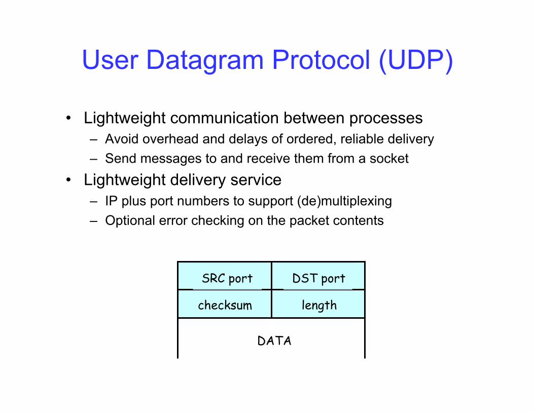
• Lightweight communication between processes – Avoid overhead and delays of ordered, reliable delivery – Send messages to and receive them from a socket
• Lightweight delivery service – IP plus port numbers to support (de)multiplexing – Optional error checking on the packet contents
SRC port DST port
checksum length
DATA
Why Would Anyone Use UDP? • Finer control over what data is sent and when
– As soon as an application process writes into the socket – … UDP will package the data and send the packet
• Low delay – UDP just blasts away without any formal preliminaries – … which avoids introducing delays such as setup
• No connection state – No allocation of buffers, parameters, sequence #s, etc. – … making it easier to handle many active clients
• Small packet header overhead – UDP header is only eight-bytes long
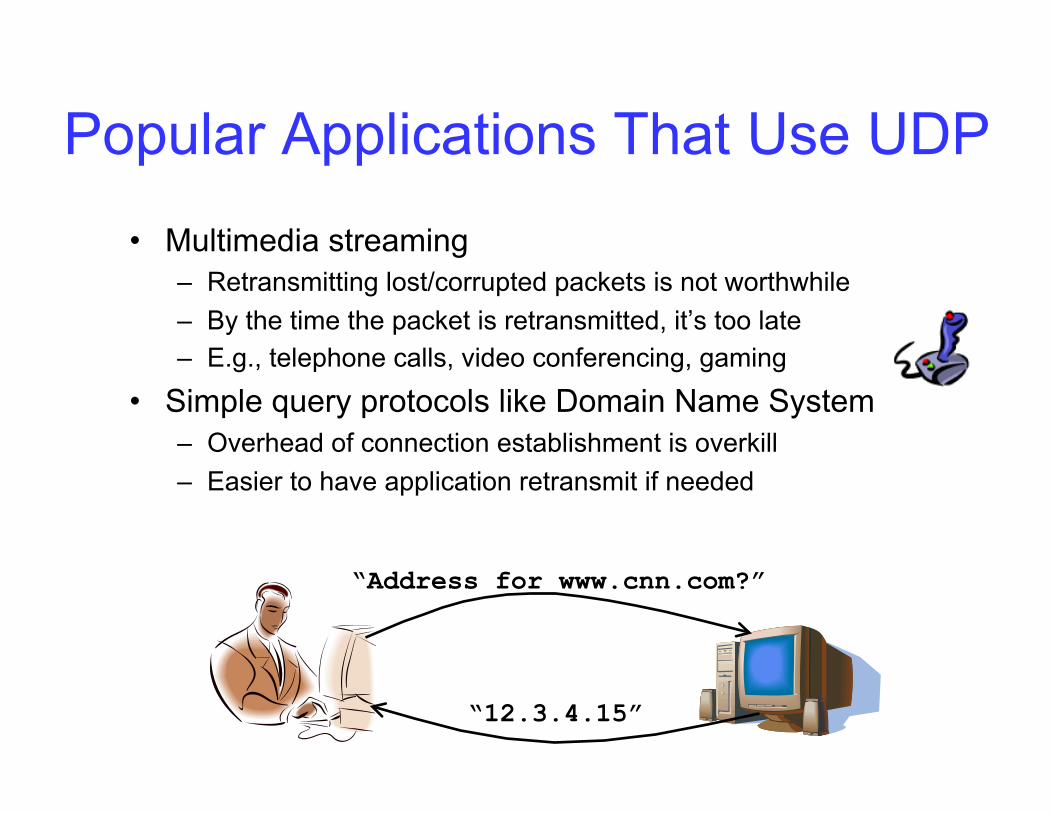
Popular Applications That Use UDP • Multimedia streaming
– Retransmitting lost/corrupted packets is not worthwhile – By the time the packet is retransmitted, it’s too late – E.g., telephone calls, video conferencing, gaming
• Simple query protocols like Domain Name System – Overhead of connection establishment is overkill – Easier to have application retransmit if needed
“Address for www.cnn.com?”
“12.3.4.15”
Transmission Control Protocol (TCP) • Connection oriented
– Explicit set-up and tear-down of TCP session • Stream-of-bytes service
– Sends and receives a stream of bytes, not messages – Similar to file I/O
• Reliable, in-order delivery – Checksums to detect corrupted data – Acknowledgments & retransmissions for reliable
delivery – Sequence numbers to detect losses and reorder data
• Flow control – Prevent overflow of the receiver’s buffer space
• Congestion control – Adapt to network congestion for the greater good
Human Analogy: Talking on a Cell Phone
• Alice and Bob talk on their cell phones • What if Bob couldn’t understand Alice?
– ..or there was a brief dropout? – Bob asks Alice to repeat what she said
• What if Bob hasn’t heard Alice for a while? – Is Alice just being quiet? – Or, have Bob and Alice lost connection? – Maybe Alice should periodically say “uh huh” – … or Bob should ask “Can you hear me now?” – How long should Bob just keep on talking?
Highlights from Previous Example
• Acknowledgments from receiver – Positive: “okay” or “ACK” – Negative: “please repeat that” or “NACK”
• Timeout by the sender (“stop and wait”) – Don’t wait indefinitely without receiving some
response – … whether a positive or a negative
acknowledgment • Retransmission by the sender
– After receiving a “NACK” from the receiver – After receiving no feedback from the receiver
TCP Support for Reliable Delivery
• Checksum – Used to detect corrupted data at the receiver – …leading the receiver to drop the packet
• Sequence numbers – Used to detect missing data – ... and for putting the data back in order
• Retransmission – Sender retransmits lost or corrupted data – Timeout based on estimates of round-trip time – Fast retransmit algorithm for rapid retransmission
TCP Segments
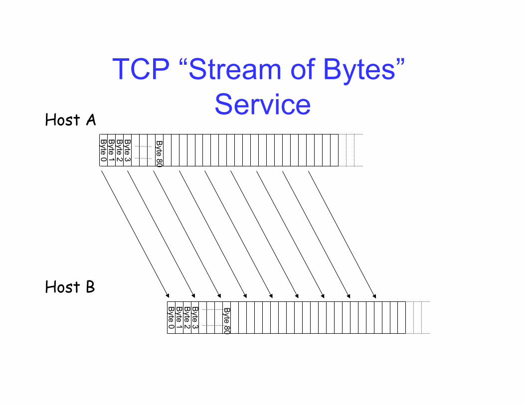
TCP “Stream of Bytes” Service
Byte 0
Byte 1
Byte 2
Byte 3
Byte 0
Byte 1
Byte 2
Byte 3
Host A
Host B
Byte 80
Byte 80
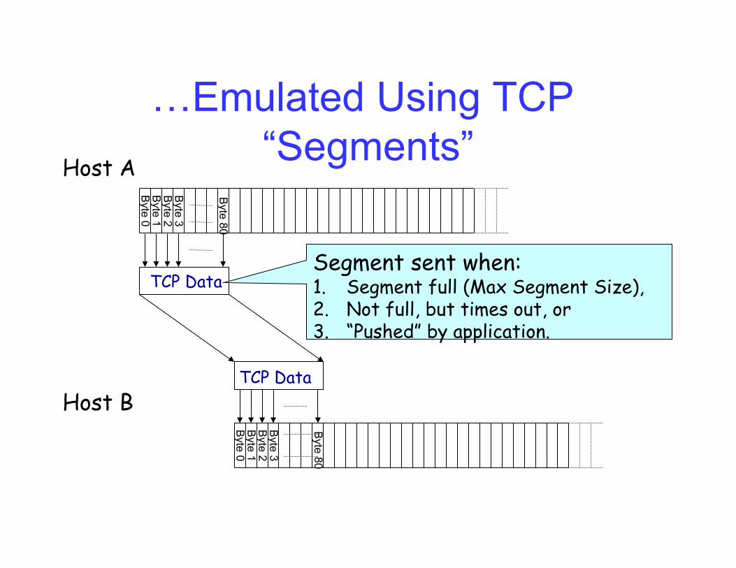
…Emulated Using TCP “Segments”
Byte 0
Byte 1
Byte 2
Byte 3
Byte 0
Byte 1
Byte 2
Byte 3
Host A
Host B
Byte 80
TCP Data
TCP Data
Byte 80
Segment sent when: 1. Segment full (Max Segment Size), 2. Not full, but times out, or 3. “Pushed” by application.
TCP Segment
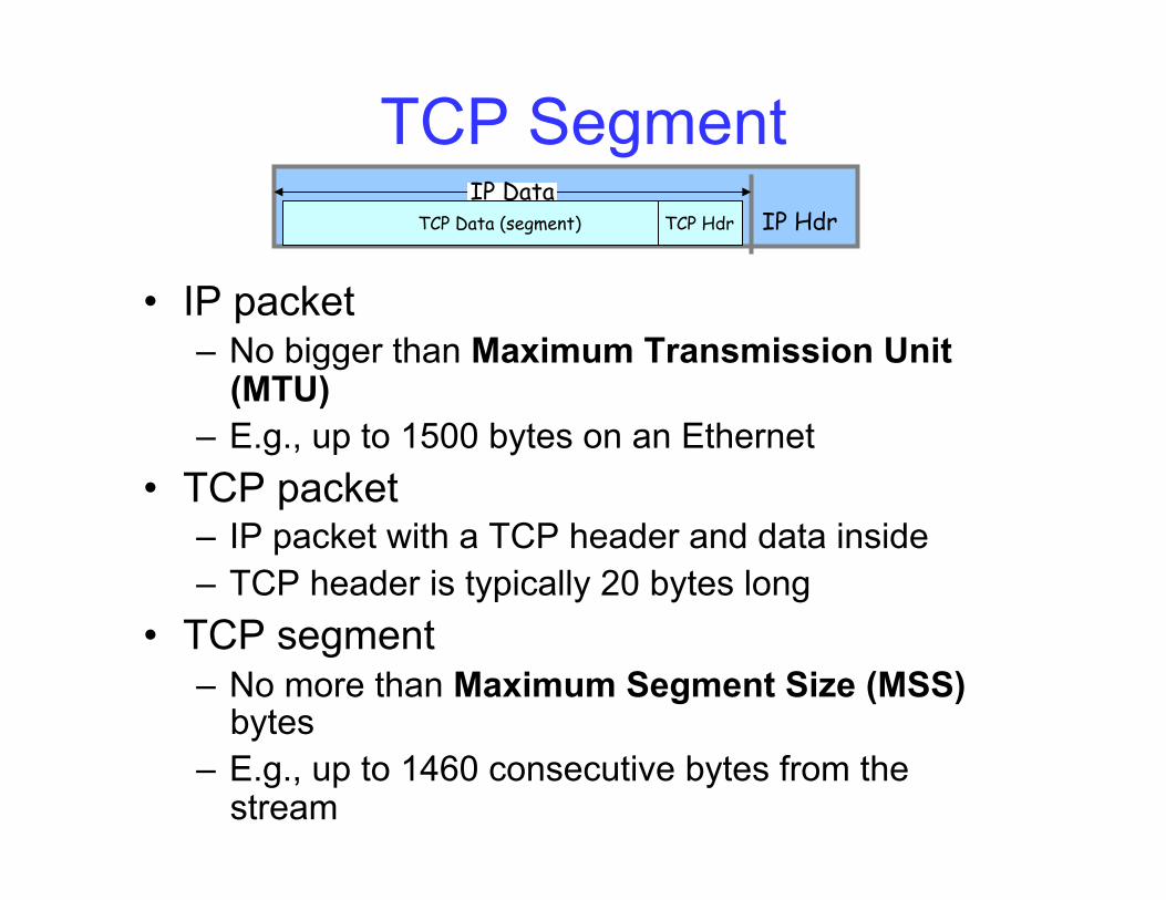
• IP packet – No bigger than Maximum Transmission Unit
(MTU) – E.g., up to 1500 bytes on an Ethernet
• TCP packet – IP packet with a TCP header and data inside – TCP header is typically 20 bytes long
• TCP segment – No more than Maximum Segment Size (MSS)
bytes – E.g., up to 1460 consecutive bytes from the
stream
IP Hdr IP Data
TCP Hdr TCP Data (segment)
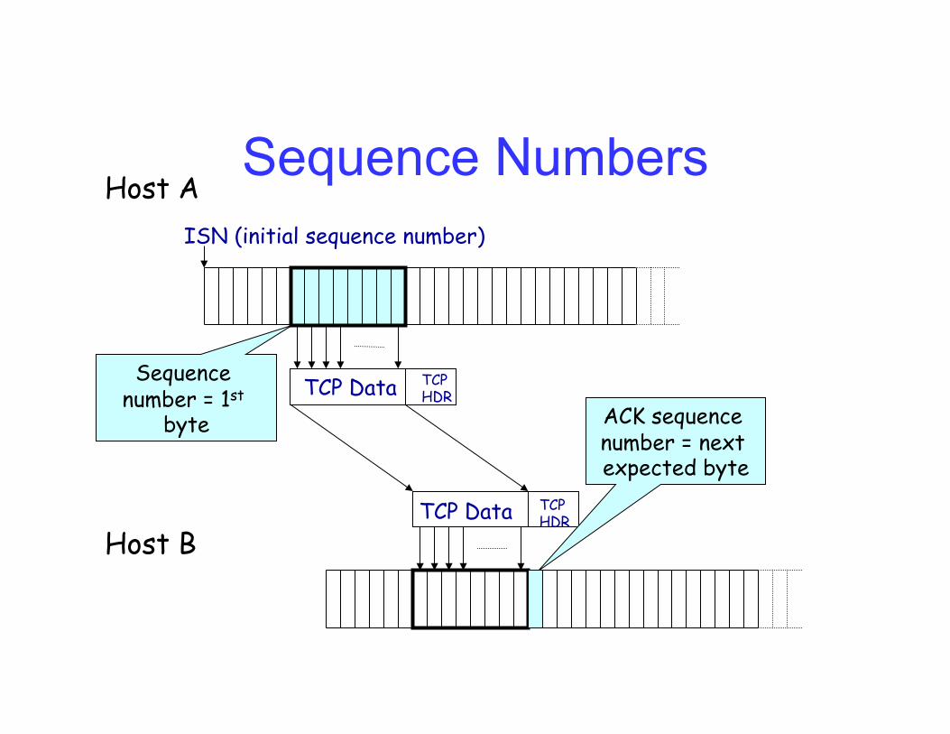
Sequence Numbers Host A
Host B
TCP Data
TCP Data
TCP HDR
TCP HDR
ISN (initial sequence number)
Sequence number = 1st
byte ACK sequence number = next expected byte
Initial Sequence Number (ISN) • Sequence number for the very first byte
– Why not a de facto ISN of 0? • Practical issue
– IP addresses and port #s uniquely identify a connection – Eventually, though, these port #s do get used again – … and there is a chance an old packet is still in flight – … and might be associated with the new connection
• Security issue – An adversary can guess ISNs and hijack a connection
• So, TCP requires changing the ISN over time – Set from a 32-bit clock that ticks every 4 microseconds – … which only wraps around once every 4.55 hours!
• But, this means the hosts need to exchange ISNs
TCP Three-Way Handshake
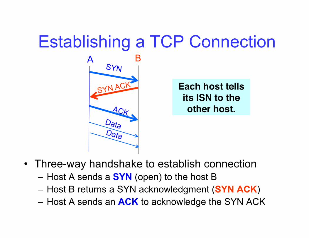
Establishing a TCP Connection
• Three-way handshake to establish connection – Host A sends a SYN (open) to the host B – Host B returns a SYN acknowledgment (SYN ACK) – Host A sends an ACK to acknowledge the SYN ACK
SYN
SYN ACK
ACK Data
A B
Data
Each host tells its ISN to the other host.!
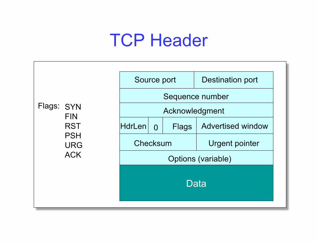
TCP Header
Source port Destination port
Sequence number
Acknowledgment
Advertised window HdrLen Flags 0
Checksum Urgent pointer
Options (variable)
Data
Flags: SYN FIN RST PSH URG ACK
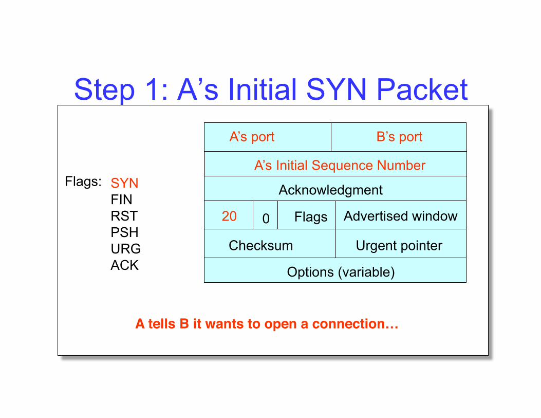
Step 1: A’s Initial SYN Packet A’s port B’s port
A’s Initial Sequence Number
Acknowledgment
Advertised window 20 Flags 0
Checksum Urgent pointer
Options (variable)
Flags: SYN FIN RST PSH URG ACK
A tells B it wants to open a connection…!
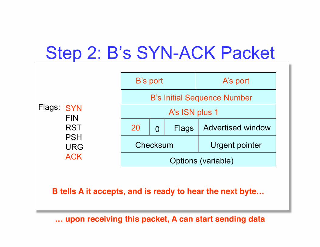
Step 2: B’s SYN-ACK Packet B’s port A’s port
B’s Initial Sequence Number
A’s ISN plus 1
Advertised window 20 Flags 0
Checksum Urgent pointer
Options (variable)
Flags: SYN FIN RST PSH URG ACK
B tells A it accepts, and is ready to hear the next byte…!
… upon receiving this packet, A can start sending data!
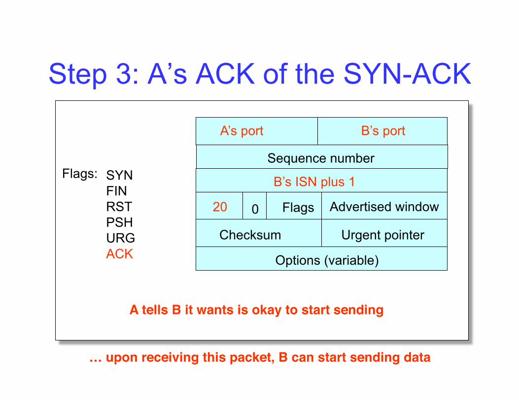
Step 3: A’s ACK of the SYN-ACK
A’s port B’s port
B’s ISN plus 1
Advertised window 20 Flags 0
Checksum Urgent pointer
Options (variable)
Flags: SYN FIN RST PSH URG ACK
A tells B it wants is okay to start sending!
Sequence number
… upon receiving this packet, B can start sending data!
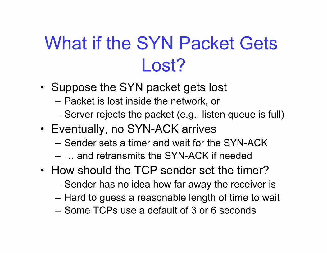
What if the SYN Packet Gets Lost?
• Suppose the SYN packet gets lost – Packet is lost inside the network, or – Server rejects the packet (e.g., listen queue is full)
• Eventually, no SYN-ACK arrives – Sender sets a timer and wait for the SYN-ACK – … and retransmits the SYN-ACK if needed
• How should the TCP sender set the timer? – Sender has no idea how far away the receiver is – Hard to guess a reasonable length of time to wait – Some TCPs use a default of 3 or 6 seconds
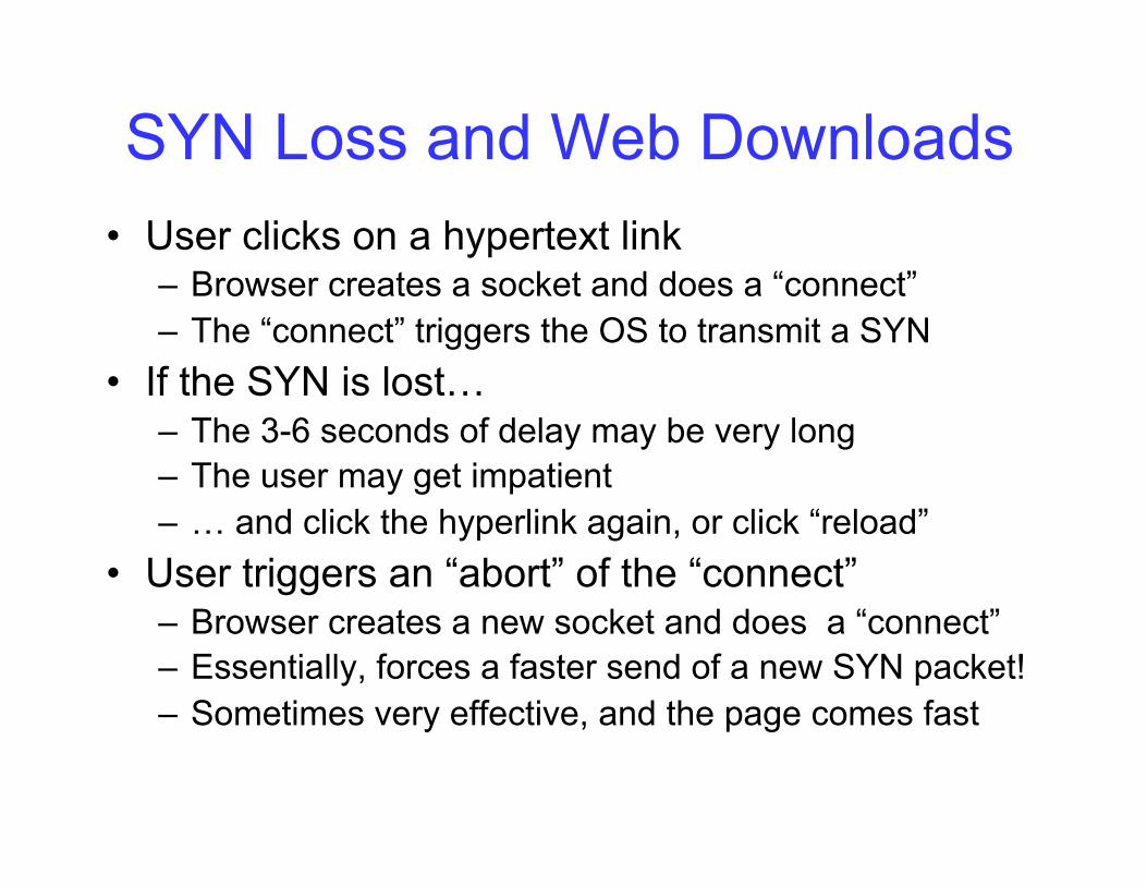
SYN Loss and Web Downloads • User clicks on a hypertext link
– Browser creates a socket and does a “connect” – The “connect” triggers the OS to transmit a SYN
• If the SYN is lost… – The 3-6 seconds of delay may be very long – The user may get impatient – … and click the hyperlink again, or click “reload”
• User triggers an “abort” of the “connect” – Browser creates a new socket and does a “connect” – Essentially, forces a faster send of a new SYN packet! – Sometimes very effective, and the page comes fast
What’s Next • Read Chapter 1, 2, 3, 4.1-4.3, and 5.1-5.2 • Next Lecture Topics from Chapter 5.3 and 5.4
– UDP and TCP
• Homework – Due Thursday in lecture
• Project 3 – Posted on the course webiste


![Pertemuan-2 Referensi OSI [Read-Only] - blog.stikom.edublog.stikom.edu/anjik/files/2012/08/Pertemuan-2-OSI.pdf · Session Layer yLapisan sesi ... Transport Layer Fungsi lapisan Transport](https://img.pdfslide.tips/doc/110x75/5acea13c7f8b9a1d328c0892/pertemuan-2-referensi-osi-read-only-blog-layer-ylapisan-sesi-transport.jpg)