Embed Size (px)
Citation preview

C.TY TNHH TỰ ĐỘNG HÓA VIỆT TRUNG 02413.281.181-0989.984.666
Website:www.viet-trung.com.vn Đ/c:194-Nguyễn Trãi-Võ Cường-TP.Bắc Ninh 1
Cutes Corporation
CT-2000F Series
AC MOTOR DRIVER
Instruction
Head Office : 2-22, Nan Yuan Road, Chung Li City, Taiwan TEL: 886 3 4612333 or 886 3 4526161 ext. 275, 266, 512 FAX: 886 3 4526227 or 886 3 4511347 E-mail: [email protected] URL: www.cutes.com.tw

C.TY TNHH TỰ ĐỘNG HÓA VIỆT TRUNG 02413.281.181-0989.984.666
bsite:www.viet-trung.com.vn Đ/c:194-Nguyễn Trãi-Võ Cường-TP.Bắc Ninh 2

C.TY TNHH TỰ ĐỘNG HÓA VIỆT TRUNG 02413.281.181-0989.984.666
Website:www.viet-trung.com.vn Đ/c:194-Nguyễn Trãi-Võ Cường-TP.Bắc Ninh 3
Introduction / Table of Contents Introduction
Thank you for choosing the CT-2000 inverter unit, this inverter unit is suitable for operating
squirrel cage induction motors. Please read this instruction manual carefully before actual
usage in order to ensure proper operation and suit your needs.
Table of Contents 1. Inspection upon receiving…………………………………………………. 4
2. Installation and Storage…………………………………………………… 4
A. Installation and………………………………………………………….. 4
B. Storage…………………………………………………………………… 4
3. Application notes…………………………………………………………… 5
4. Block diagram and Wiring ………………………………………………… 5
A. Wiring of main and control circuit …………………………………… 5
B. Signal circuit……………………………………………………………. 5
C. Connecting the power supply and the AC motor…………………… 6
D. R.S.T. for Power source reactor……………………………………… 7
E. Standard external connection diagram……………………………… 8
F. Control circuit specification………………………………………….... 9
G. Terminal specifications……………………………………………….. 10
5. Operation Test……………………………………………………………… 11
6. Function Setup and Specification.……………………………………….. 13
A. Keypad operation………………………………………………………. 13
B. Display specification…………………………………………………… 14
C. Keypad specification…………………………………………………… 14
D. Function Code………………………………………………………….. 15
7. Description of alarm display indications ………………………………… 45
8. Troubleshooting……………………………………………………………. 47
9. Maintenance and Inspection……………………………………………… 49
10. Standard Specification…………………………………………………….. 50
A. 200V series……………………………………………………………… 50
B. 400V series……………………………………………………………… 50
C. Standard specification………………………………………………….. 51
D. Outline dimension………………………………………………………. 52
11. Function code Table……..………………………………………………. 53
12. Modbus Address of Display Data….…………………………………… 60
13. Series Communication User Manual..…………………………………. 62
A. The physical link………………………………………………………… 62
B. Data structure in communication……………………………………… 63
C.TY TNHH TỰ ĐỘNG HÓA VIỆT TRUNG 02413.281.181-0989.984.666
Website:www.viet-trung.com.vn Đ/c:194-Nguyễn Trãi-Võ Cường-TP.Bắc Ninh 4
C. Function code in Modbus……………………………………………… 66
D. Error check generation………………………………………………… 67
E. Group & global broadcasting…………………………………………. 69
- 3 -
C.TY TNHH TỰ ĐỘNG HÓA VIỆT TRUNG 02413.281.181-0989.984.666
Website:www.viet-trung.com.vn Đ/c:194-Nguyễn Trãi-Võ Cường-TP.Bắc Ninh 5
Inspection upon receiving / Installation and storage
1. Inspection upon receiving
A. Check that the model, the capacity and power voltage specifications are as
ordered.
B. Check that no damage has occurred during transportation.
C. Check that none of the internal parts have been damaged or have fallen off.
D. Check that none of the connectors have been damaged or have fallen off.
E. Check that there is no loosening of the terminals or screws of each of the parts.
2. Installation and Storage
A. Storage:
If the equipment is not to be installed immediately, it should be stored in a clean and
dry location at ambient temperatures from 20℃to 55℃. The surrounding air must
be free of corrosive contaminants.
B. Installation place:
Places where the peripheral temperature is from -10℃to 40℃, and where the
relative humidity is 90% or less. Avoid installing at places where there is dust, iron
particles, corrosive gas, water spray, direct sunlight or too much vibration. And
places where has good ventilation.
10cm min.
10cm min.
10cm min.
10cm min.

C.TY TNHH TỰ ĐỘNG HÓA VIỆT TRUNG 02413.281.181-0989.984.666
Website:www.viet-trung.com.vn Đ/c:194-Nguyễn Trãi-Võ Cường-TP.Bắc Ninh 6
- 4 -

C.TY TNHH TỰ ĐỘNG HÓA VIỆT TRUNG 02413.281.181-0989.984.666
Website:www.viet-trung.com.vn Đ/c:194-Nguyễn Trãi-Võ Cường-TP.Bắc Ninh 7
Block diagram, wiring 3. Application notes
A. Concerning the inverter unit:
(1) Do not fit capacitors to the output side of the inverter in order to improve the
power ratio.
(2) In case of fitting MC between inverter and motor to control motor operation,
then the capacity of inverter must be 6 times the capacity of motor.
(3) Run a motor that is within the capacity of the inverter unit, light load current and
no-load current will cause the motor to develop ripple current.
(4) This unit is provided with a current limiting function. The starting torque is
assumed to be from 80% to 100%.
B. Concerning the AC motor
(1) When general-purpose motors are operated at low speeds, there is a reduced
cooling effect, please apply the special purpose motor.
(2) Operation at frequencies exceeding 60 Hz requires caution, as there is the
danger of the mechanical strength failure of the motor.
(3) When motors with brakes are being operated, the power for the brake and
inverter should be taken from the same power supply and the brake operation
must be in phase when the unit is started and stopped.
4. Block diagram, Wiring
A. Wiring of main and control circuit
Wire according to the standard connection diagram. On using the external
sequence control, please use small signal relay or double terminal relay to avoid
relay terminal malfunction.
B. Signal circuit
The signal circuit uses either shielded pairs or twisted pairs, should be wired either
using a wiring duct separated from that for the power circuit, or with the wiring
conduit isolated as much as possible.

C.TY TNHH TỰ ĐỘNG HÓA VIỆT TRUNG 02413.281.181-0989.984.666
Website:www.viet-trung.com.vn Đ/c:194-Nguyễn Trãi-Võ Cường-TP.Bắc Ninh 8
- 5 -
C.TY TNHH TỰ ĐỘNG HÓA VIỆT TRUNG 02413.281.181-0989.984.666
Website:www.viet-trung.com.vn Đ/c:194-Nguyễn Trãi-Võ Cường-TP.Bắc Ninh 9
Block diagram, wiring
C. Connecting the power supply and the AC motor
Connect the main circuit, by wiring according to the main circuit terminal connection
diagram. Care is required not to make a mistake when connecting the input and
output terminals, lest it will cause inverter damage. Specifications of main circuit
path and NFB are as follow:
Voltage (V) Model NFB (A) Wire size for circuit (mm2)
CT-2002-A75 6A 2~5.5 CT-2002-1A5 10A 2~5.5 CT-2002-2A2 15A 3.5~5.5 CT-2002-3A7 20A 5.5 CT-2002-5A5 30A 5.5~8 CT-2002-7A5 40A 5.5~8
220
380
| 440
CT-2002-011 60A 22 CT-2002-015 80A 30 CT-2002-022 120A 38 CT-2002-030 150A 38~100 CT-2002-037 200A 38~100 CT-2002-045 250A 60~100 CT-2002-055 300A 100 CT-2002-075 400A 100~200 CT-2002-093 500A 100~200 CT-2004-A75 5A 2~5.5 CT-2004-1A5 5A 2~5.5 CT-2004-2A2 7.5A 2~5.5 CT-2004-3A7 10A 3.5~5.5 CT-2004-5A5 15A 3.5~5.5 CT-2004-7A5 20A 5.5 CT-2004-011 30A 8~14 CT-2004-015 40A 8~14 CT-2004-022 60A 22 CT-2004-030 80A 22 CT-2004-037 100A 30 CT-2004-045 120A 50 CT-2004-055 150A 38~100 CT-2004-075 200A 38~100 CT-2004-093 250A 60~100 CT-2004-112 300A 100

C.TY TNHH TỰ ĐỘNG HÓA VIỆT TRUNG 02413.281.181-0989.984.666
Website:www.viet-trung.com.vn Đ/c:194-Nguyễn Trãi-Võ Cường-TP.Bắc Ninh 10
- 6 -

C.TY TNHH TỰ ĐỘNG HÓA VIỆT TRUNG 02413.281.181-0989.984.666
Website:www.viet-trung.com.vn Đ/c:194-Nguyễn Trãi-Võ Cường-TP.Bắc Ninh 11
Block diagram, wiring
D. Instantaneous current and to improve power ratio, it should be fitted the A.C.L. to R.S.T. input side under the following circumstance:
a. Where power supply capacity is larger than 500 KVA.
b. Using thyrister, phase advance capacitor etc. from the same power supply.
A.C.L. Specifications table: Voltage (V) Model Current (Ar.m.s) Induction Value
CT-2002-A75 6A 1.8mH CT-2002-1A5 10A 1.1mH CT-2002-2A2 15A 0.71mH CT-2002-3A7 20A 0.53mH CT-2002-5A5 30A 0.35mH CT-2002-7A5 40A 0.26mH
220
380
| 440
CT-2002-011 60A 0.18mH CT-2002-015 80A 0.13mH CT-2002-022 120A 0.09mH CT-2002-030 150A 70uH CT-2002-037 200A 50uH CT-2002-045 250A 44uH CT-2002-055 300A 35uH CT-2002-075 400A 27uH CT-2002-093 500A 21uH CT-2004-A75 5A 4.2mH CT-2004-1A5 5A 4.2mH CT-2004-2A2 7.5A 3.6mH CT-2004-3A7 10A 2.2mH CT-2004-5A5 15A 1.42mH CT-2004-7A5 20A 1.0mH CT-2004-011 30A 0.7mH CT-2004-015 40A 0.53mH CT-2004-022 60A 0.36mH CT-2004-030 80A 0.26mH CT-2004-037 100A 0.21mH CT-2004-045 120A 0.18mH CT-2004-055 150A 0.14mH CT-2004-075 200A 0.11mH CT-2004-093 250A 0.10mH CT-2004-112 300 70uH
Notes: The A.C.L. for 220V and 380V/460V have different induction values, please does
not mix up.

C.TY TNHH TỰ ĐỘNG HÓA VIỆT TRUNG 02413.281.181-0989.984.666
Website:www.viet-trung.com.vn Đ/c:194-Nguyễn Trãi-Võ Cường-TP.Bắc Ninh 12
- 7 -

C.TY TNHH TỰ ĐỘNG HÓA VIỆT TRUNG 02413.281.181-0989.984.666
Website:www.viet-trung.com.vn Đ/c:194-Nguyễn Trãi-Võ Cường-TP.Bắc Ninh 13
Block diagram, wiring
E. Standard External Connection Diagram
(Note: While external is required for DBR, disconnect inter DBR first
TM
DBR
P PR N
3-phase power 200V/50Hz 200~230V/50,60Hz
400V/50Hz 400~460V/50,60Hz
Ext. Operation controller
5KΩ 1/2W
ACL
R
S
T
E
10V
IN3
CC
Adaptor
Voltage detect
Current detect
Braking control
interface
Convertor
U
V
IM
W
Ext. Operation
controller 5KΩ 1/2W
External signal 4〜20mA
10V
IN2
CC
IN1
0V
CPU
Power control
Operational
panel
VOUT
CC
Analog output terminal
Terminal 1
Terminal 2
Terminal 3
Terminal 4
Terminal 5
Terminal 6
Reverse operation
Forward operation
Twisted or shield wires
DI1
DI2
DI3
DI4
DI5
DI6
RR
FR
COM
RJ45
REMOTE
A+ A-
B+ B-
C1
NO1
NC1
C2
NO2
NC2
Multi-function Relay output terminal 1
Multi-function Relay output terminal 2
RS422/485 Series communication interface terminal

C.TY TNHH TỰ ĐỘNG HÓA VIỆT TRUNG 02413.281.181-0989.984.666
Website:www.viet-trung.com.vn Đ/c:194-Nguyễn Trãi-Võ Cường-TP.Bắc Ninh 14
- 8 -
C.TY TNHH TỰ ĐỘNG HÓA VIỆT TRUNG 02413.281.181-0989.984.666
Website:www.viet-trung.com.vn Đ/c:194-Nguyễn Trãi-Võ Cường-TP.Bắc Ninh 15
Block diagram, wiring
F. Control circuit
C1 NO1 NC1 C2 NO2 NC2
No.1 Multifunctional
relay output terminal
No.2 Multifunctional
relay output terminal
Vout IN1 IN2 IN3 VC CC
0-10V
DC
4-20mA Current Set
Accessory
Voltage
1/2W 5K ohm
Voltage Output
Set
Main Voltage Set
1/2W 5K ohm
AC2 DC2 3DF JOG 2DF RST
COM 1 2 3 4 5 6 RR FR
COM
Multi- functional
Multi- functional
Multi- functional
Reverse
Forward
input terminal
input terminal
input terminal
operation operation

C.TY TNHH TỰ ĐỘNG HÓA VIỆT TRUNG 02413.281.181-0989.984.666
Website:www.viet-trung.com.vn Đ/c:194-Nguyễn Trãi-Võ Cường-TP.Bắc Ninh 16
- 9 -
C.TY TNHH TỰ ĐỘNG HÓA VIỆT TRUNG 02413.281.181-0989.984.666
Website:www.viet-trung.com.vn Đ/c:194-Nguyễn Trãi-Võ Cường-TP.Bắc Ninh 17
Block diagram, wiring
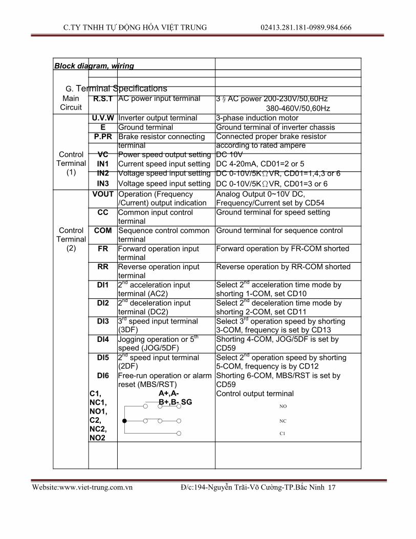
G. Terminal Specifications Main
Circuit R.S.T AC power input terminal 3∮AC power 200-230V/50,60Hz
380-460V/50,60Hz U.V.W Inverter output terminal 3-phase induction motor
E Ground terminal Ground terminal of inverter chassis
P.PR Brake resistor connecting terminal
Connected proper brake resistor according to rated ampere
Control Terminal
(1)
VC Power speed output setting DC 10V IN1 Current speed input setting DC 4-20mA, CD01=2 or 5 IN2 Voltage speed input setting DC 0-10V/5KΩVR, CD01=1,4,3 or 6
IN3 Voltage speed input setting DC 0-10V/5KΩVR, CD01=3 or 6
Control Terminal
(2)
VOUT Operation (Frequency /Current) output indication
CC Common input control terminal
COM Sequence control common terminal
FR Forward operation input terminal
RR Reverse operation input terminal
DI1 2nd acceleration input terminal (AC2)
DI2 2nd deceleration input terminal (DC2)
DI3 3rd speed input terminal (3DF)
DI4 Jogging operation or 5th
speed (JOG/5DF)
DI5 2nd speed input terminal (2DF)
DI6 Free-run operation or alarm reset (MBS/RST)
Analog Output 0~10V DC, Frequency/Current set by CD54 Ground terminal for speed setting Ground terminal for sequence control Forward operation by FR-COM shorted Reverse operation by RR-COM shorted
Select 2nd acceleration time mode by shorting 1-COM, set CD10 Select 2nd deceleration time mode by shorting 2-COM, set CD11 Select 3rd operation speed by shorting 3-COM, frequency is set by CD13 Shorting 4-COM, JOG/5DF is set by CD59 Select 2nd operation speed by shorting 5-COM, frequency is by CD12 Shorting 6-COM, MBS/RST is set by CD59
C1, NC1, NO1, C2, NC2, NO2
A+,A- B+,B- SG
Control output terminal
NO
NC
C1

C.TY TNHH TỰ ĐỘNG HÓA VIỆT TRUNG 02413.281.181-0989.984.666
Website:www.viet-trung.com.vn Đ/c:194-Nguyễn Trãi-Võ Cường-TP.Bắc Ninh 18
Serial communication terminal
Multifunctional relay output terminal Connector capacity AC 220V, 0.1A While normal C-X closed and NC-X Closed While operating C-X open and NO-X closed Functions of C1, NC1, NO1 are set by CD47 Functions of C2, NC2, NO2 are set by CD48 Refer to Serial Communications User Manual. SG is 0 volt terminal of the digital signal.
- 10 -

C.TY TNHH TỰ ĐỘNG HÓA VIỆT TRUNG 02413.281.181-0989.984.666
Website:www.viet-trung.com.vn Đ/c:194-Nguyễn Trãi-Võ Cường-TP.Bắc Ninh 19
FN-800
FN-800
Operation Test 5. Operational Test
A. Check before test
Please check the following:
(1) Is wiring correct? Check especially the input and output terminals.
(2) Is there a short-circuit or ground connection on external wiring?
(3) Make sure there is no loosening of screws.
(4) Check external sequence control circuit.
(5) Check voltage of power supply.
B. Operation Method
CT-2000 series inverter unit has both operator panel and external operation methods.
(1) Operator panel
M
PANEL INPUT
CT2000
(2) External signal operation
MCB
M
SWITCH CONTROL
CT2000

C.TY TNHH TỰ ĐỘNG HÓA VIỆT TRUNG 02413.281.181-0989.984.666
Website:www.viet-trung.com.vn Đ/c:194-Nguyễn Trãi-Võ Cường-TP.Bắc Ninh 20
- 11 -
C.TY TNHH TỰ ĐỘNG HÓA VIỆT TRUNG 02413.281.181-0989.984.666
Website:www.viet-trung.com.vn Đ/c:194-Nguyễn Trãi-Võ Cường-TP.Bắc Ninh 21
Operational Test
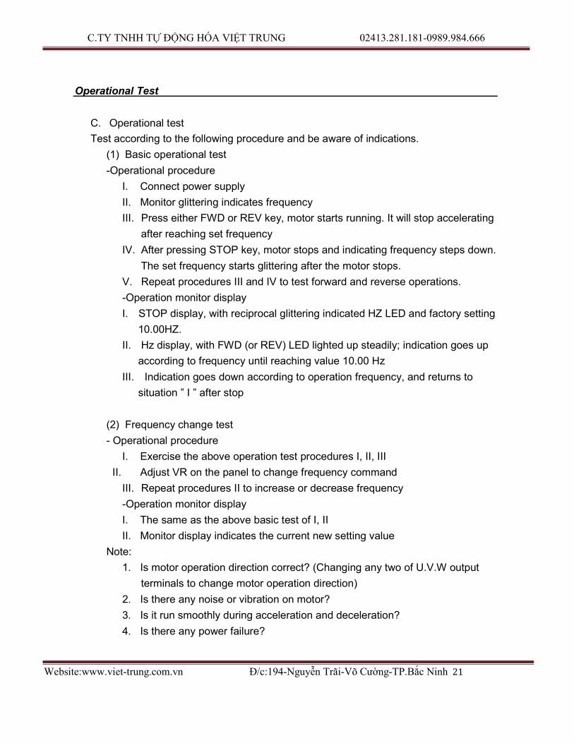
C. Operational test
Test according to the following procedure and be aware of indications.
(1) Basic operational test
-Operational procedure
I. Connect power supply
II. Monitor glittering indicates frequency
III. Press either FWD or REV key, motor starts running. It will stop accelerating
after reaching set frequency
IV. After pressing STOP key, motor stops and indicating frequency steps down.
The set frequency starts glittering after the motor stops.
V. Repeat procedures III and IV to test forward and reverse operations.
-Operation monitor display
I. STOP display, with reciprocal glittering indicated HZ LED and factory setting
10.00HZ.
II. Hz display, with FWD (or REV) LED lighted up steadily; indication goes up
according to frequency until reaching value 10.00 Hz
III. Indication goes down according to operation frequency, and returns to
situation ” I ” after stop
(2) Frequency change test
- Operational procedure
I. Exercise the above operation test procedures I, II, III
II. Adjust VR on the panel to change frequency command
III. Repeat procedures II to increase or decrease frequency
-Operation monitor display
I. The same as the above basic test of I, II
II. Monitor display indicates the current new setting value
Note:
1. Is motor operation direction correct? (Changing any two of U.V.W output
terminals to change motor operation direction)
2. Is there any noise or vibration on motor?
3. Is it run smoothly during acceleration and deceleration?
4. Is there any power failure?

C.TY TNHH TỰ ĐỘNG HÓA VIỆT TRUNG 02413.281.181-0989.984.666
Website:www.viet-trung.com.vn Đ/c:194-Nguyễn Trãi-Võ Cường-TP.Bắc Ninh 22
- 12 -

C.TY TNHH TỰ ĐỘNG HÓA VIỆT TRUNG 02413.281.181-0989.984.666
Website:www.viet-trung.com.vn Đ/c:194-Nguyễn Trãi-Võ Cường-TP.Bắc Ninh 23
Adjust and Function Specification 6. Adjust and Function Specification A. Keypad operation
Operator panel parts names and functions
7-segement monitor
1.Displays frequency Cd02=0
Displays current Cd02=1 Displays RPM NO2=2
Displays various readings see Cd02
2. After indicates alarm, ignore Cd02, directly
displays failure status
READY Displays that the panel is ready to accept key input
Monitor mode display
Displays monitor status
Ten-key pad
Data input key
Operation monitor display
Displays forward/reverse/stop status
Cutes Corporation
。READY 。HZ 。A
。ALARM
7 8 9 4 5 6
Operation instruction
keys
Control from keyboard External control operation, stop
mode by set Cd04=1
FWD
PROG
REV
READ
STOP 1 1 2 3
SET 1 0 .
STOP key
1. Stops inverter operation 2. Resets function
3. Resets alarm indication
Step keys
1. To change frequency 2. Select function items
Function setting keys
These three keys offer selecting read or setting value of function

C.TY TNHH TỰ ĐỘNG HÓA VIỆT TRUNG 02413.281.181-0989.984.666
Website:www.viet-trung.com.vn Đ/c:194-Nguyễn Trãi-Võ Cường-TP.Bắc Ninh 24
- 13 -
C.TY TNHH TỰ ĐỘNG HÓA VIỆT TRUNG 02413.281.181-0989.984.666
Website:www.viet-trung.com.vn Đ/c:194-Nguyễn Trãi-Võ Cường-TP.Bắc Ninh 25
Adjust and Function Specification
B. Display specification
LED Display specification
READY READY LED means the Keyboard working normally.
HZ Hz LED means of recent revolution frequency.
A A LED means of recent revolution current.
FWD FWD LED means motor operate at forward direction.
REV REV LED means motor operate at reverse direction.
STOP STOP LED means motor operate at stop.
C. Keyboard specification
Bottom Function Bottom specification
MOTOR RUN Push keypad to control forward of motor, and screen
FWD display main display content (Cd02 setting).
REV
MOTOR RUN Push keypad to control reverse of motor, and screen
display main display content (Cd02 setting).
STOP
STOP Stop motor revolution when push STOP key, and on the
mean time screen flashing with commanding
instruction.
RESET While failure occurred, press STOP key to re-start inverter and save failure in failure memory.
PROG
SELECT
FUNCTION
In display mode, press PROG key and screen shows
Cd00 (General parameter input area). Press
PROG/SET key again and screen shows CE-00 (failure
and engineering mode). If pressed PROG/SET key
now, screen would return to display mode.
READ
SET

C.TY TNHH TỰ ĐỘNG HÓA VIỆT TRUNG 02413.281.181-0989.984.666
Website:www.viet-trung.com.vn Đ/c:194-Nguyễn Trãi-Võ Cường-TP.Bắc Ninh 26
READ When display shows Cd- (General parameter Input mode) or CE- (Failure display and engineeri
CANCEL Press READ at parameter input mode can escape from parameter input mode and
SET and
SAVE In parameter input mode, press SET key will save new
parameter just input.
- 14 -

C.TY TNHH TỰ ĐỘNG HÓA VIỆT TRUNG 02413.281.181-0989.984.666
Website:www.viet-trung.com.vn Đ/c:194-Nguyễn Trãi-Võ Cường-TP.Bắc Ninh 27
Adjust and Function Specification
Item of display
changing
Parameter
▲ selection
▼
Parameter
modification
Press▲,▼ key at display mode, select required item.
Press ▲,▼ key to change value when screen
shows Cd- (General parameter input area) or
CE- (Failure display and engineering mode). Press and hold ▲,▼ key can progressively increase or
decrease value.
Press ▲,▼ key at parameter input mode can change
parameter. Using with SET key to modify parameter.
Input a number Input a number
0
9
•
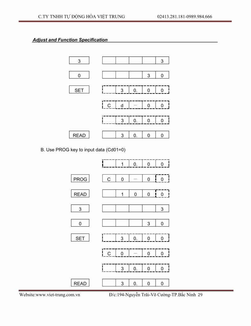
D. Function Code
§Cd00 Set frequency (settable range 0.5-240 HZ)
There are 5 methods to change set frequency. Items A~C are methods of panel key
operation, items D-E are methods of external terminal input.
A. At display function, press READ and setting (Cd01=0)
B. Use PROG key to input data (Cd01=0)
C. Use ▼、▲ key to input data (Cd01=0)
D. Use Multi-Step function to setting (Refer to function CE05 to CE55.)
E. Set external voltage
F. Set external current
Note:
1. Set value should be in accordance with V/F slope (Cd05) and upper limit
frequency (Cd17).
Set by function key
A. At display function, press READ and setting (Cd01=0)

C.TY TNHH TỰ ĐỘNG HÓA VIỆT TRUNG 02413.281.181-0989.984.666
Website:www.viet-trung.com.vn Đ/c:194-Nguyễn Trãi-Võ Cường-TP.Bắc Ninh 28
1 0. 0 0
READ 1 0. 0 0
- 15 -
C.TY TNHH TỰ ĐỘNG HÓA VIỆT TRUNG 02413.281.181-0989.984.666
Website:www.viet-trung.com.vn Đ/c:194-Nguyễn Trãi-Võ Cường-TP.Bắc Ninh 29
Adjust and Function Specification
3 3
0 3 0
SET 3 0. 0 0
C d - 0 0
3 0. 0 0
READ 3 0. 0 0
B. Use PROG key to input data (Cd01=0)
1 0. 0 0
PROG C 0 - 0 0
READ 1 0 0 0
3 3
0 3 0
SET 3 0. 0 0
C 0 - 0 0
3 0. 0 0
READ 3 0. 0 0

C.TY TNHH TỰ ĐỘNG HÓA VIỆT TRUNG 02413.281.181-0989.984.666
Website:www.viet-trung.com.vn Đ/c:194-Nguyễn Trãi-Võ Cường-TP.Bắc Ninh 30
Note: , Indicate 7 Segment LED flash.
- 16 -

C.TY TNHH TỰ ĐỘNG HÓA VIỆT TRUNG 02413.281.181-0989.984.666
Website:www.viet-trung.com.vn Đ/c:194-Nguyễn Trãi-Võ Cường-TP.Bắc Ninh 31
Adjust and Function Specification
§Cd01 Setting procedure of frequency (Selective range 0-7)
The function cannot be modified during revolution.
Setting procedure of frequency is to select either panel key or external analog signal.
Cd01=0 Set frequency on operation panel, as the above items A-C.
Cd01=1 Set frequency by terminal In2 DC 0-10V/5KΩVR
Cd01=2 Set frequency by terminal In1 DC 4-20mA
Cd01=3 Set frequency by terminal In2+IN3 DC 0-10V/5KΩVR
Cd01=4 Setting from terminal In2, input DC0〜10V/VR 5KΩ hysteresis
Cd01=5 Setting from terminal In1, input DC4〜20mA hysteresis
Cd01=6 Setting from terminal In2+IN3, input DC0〜10V/VR 5KΩ hysteresis
Cd01=7 Set frequency by Multi-step function mode
§Cd02 Select Main monitor display (Selective range 0-15)
The monitor is consisted of four 7-segment LEDs, displays frequency, current and
various data by digital number and character.
Cd02=0 Display the frequency, LED HZ active
Cd02=1 Display the current, LED I active Cd02=2 Display Ultimate speed, Hz and I LED de-active. Cd02=3 Display DC voltage of DC BUS, showing d in front of value
Cd02=4 Display rms value of U.V.W. AC output,LED HZ, I active
Cd02=5 Display external control terminal status, showing E in front of value Cd02=6 Display temperature rising of PIM module, showing b in front of value
Cd02=7 Display speed feedback. Check if MCK circuit working properly, then
the restart and free run start function (Cd28) will working normally.
Cd02=8 Display average speed of multi-step function (rpm)
Cd02=9 Display current step of multi-step function (step)
Cd02=10 Display current time of multi-step function (minutes)
Cd02=11 Display Yards counter value
Cd02=12 Display power factor (cos Θ)
Cd02=13 Display transient power (Kw)
Cd02=14 Display Kw-h
Cd02=15 Display Mw-h
§Cd03 Torque mode (Selective range 0,1)
The function cannot be modified during revolution.

C.TY TNHH TỰ ĐỘNG HÓA VIỆT TRUNG 02413.281.181-0989.984.666
Website:www.viet-trung.com.vn Đ/c:194-Nguyễn Trãi-Võ Cường-TP.Bắc Ninh 32
Cd03=0 Automatic torque compensation de-active, set compensation by Cd07. Cd03=1 Initial Torque boost active, Maximum boost is 1.5 * Cd07 setting value.
Start boost while operation frequency greater than 3 Hz. Cd03=2 Initial Torque boost active, Maximum boost is 1.5 * Cd07 setting value.
Start boost while operation frequency greater than 1.5 Hz.
- 17 -

C.TY TNHH TỰ ĐỘNG HÓA VIỆT TRUNG 02413.281.181-0989.984.666
Website:www.viet-trung.com.vn Đ/c:194-Nguyễn Trãi-Võ Cường-TP.Bắc Ninh 33
Adjust and Function Specification
§Cd04 Operation command mode (Selective range 0,1)
The function cannot be modified during revolution.
Cd04=0 Operation on operation panel
Cd04=1 Operation by external terminal, including FR, RR, terminal (1, 2, 3, 4, 5, 6)
§Cd05 Set V/F pattern (Selective range 1-14)
The function cannot be modified during revolution.
There are 11 patterns of V/F slope, as follow:
V V V V
1 2 3 4 F F F F
50HZ 60HZ 50HZ 100HZ 60HZ 120HZ V V V V
5 6 7 8
F F F F 50HZ 150HZ 60HZ 180HZ 50HZ 200HZ 60HZ 240HZ
V V
9 10
F F
87HZ 174HZ 103HZ 206HZ
When Cd05=11, V/F slope is determined by Cd57, Cd58.
Cd05=12 1.5 power curve
Cd05=13 1.7 power curve V
Cd05=14 square curve
F
60HZ
§Cd06 Motor current rate (Settable range 25-100)
Set motor overload protective current, in order to avoid motor failure because of
overload. Set value=100, please calculate the following formula:
Set Value = Motor rated current / Inverter rated current ×100
Ex. Use inverter with 3.7KW(5HP) to drive motor with 2.2KW(3HP)

C.TY TNHH TỰ ĐỘNG HÓA VIỆT TRUNG 02413.281.181-0989.984.666
Website:www.viet-trung.com.vn Đ/c:194-Nguyễn Trãi-Võ Cường-TP.Bắc Ninh 34
Inverter rated current = 17.4A
Motor rated current = 8A
Set Value = 8 / 17.4 ×100 = 46%
- 18 -

C.TY TNHH TỰ ĐỘNG HÓA VIỆT TRUNG 02413.281.181-0989.984.666
Website:www.viet-trung.com.vn Đ/c:194-Nguyễn Trãi-Võ Cường-TP.Bắc Ninh 35
Outp
ut
Vo
ltage
VB
Adjust and Function Specification
§Cd07 Torque compensation Vb (Settable range 0-150)
The function cannot be modified during revolution.
This function is to raise output voltage to increase torque of motor.
It can also be used to increase load slope of low voltage produced by long wiring
between inverter and motor, as well as fluid, fan and pump.
100%
50%
15%
FS
0% Output Frequency (HZ)
§Cd08, 09, 10, 11 Acceleration / deceleration time (Settable range 0.1-6000)
The time needed for set frequency from 0Hz to 50Hz.
There are 2 selections for each of acceleration time and deceleration time.
To set acceleration/deceleration time
Set Value (T) = (50 - 0) / △F ×T1
T1: time needed for accelerate / decelerate
△F: frequency changed
Ex.: Frequency from 50Hz down to 30Hz, needed time 1 sec. Then:
Set Value (T) = 50 / 50 - 30 ×1 = 2.5
Cd08 = Acceleration time
Cd09 = Deceleration time
Cd10 = 2nd Acceleration time
Cd11 = 2nd Deceleration time
Note: The 2nd acceleration / deceleration time only available on external
operation mode. (e.g. Cd04=1)
§Cd12, 13, 14 Speed setting (Settable range 0.5-240)
This function has 4 kinds of speed setting
The 2nd , 3rd, 4th speeds are set from external terminal FR (or RR) which accommodate
terminal 3, 5, the setting value cannot exceed the allowed range.
Cd12 = 2nd speed setting

C.TY TNHH TỰ ĐỘNG HÓA VIỆT TRUNG 02413.281.181-0989.984.666
Website:www.viet-trung.com.vn Đ/c:194-Nguyễn Trãi-Võ Cường-TP.Bắc Ninh 36
Cd13 = 3rd speed setting
Cd14 = 4th speed setting
Note: When apply to multi-speed setting, use external control (e.g. Cd04=1) to start
and use panel to pre-input to set frequency.
- 19 -

C.TY TNHH TỰ ĐỘNG HÓA VIỆT TRUNG 02413.281.181-0989.984.666
Website:www.viet-trung.com.vn Đ/c:194-Nguyễn Trãi-Võ Cường-TP.Bắc Ninh 37
Adjust and Function Specification
§Cd15 Jogging frequency (Settable range 0.5-30)
To control jogging, use external terminal 4-FR or 4-RR with COM shorted.
Set running direction
FR or RR
2
Running mode:
Jogging
Forward(Reverse)
Note: Jogging operation is valid only when operation command selects the
external operation signal mode (e.g. Cd04=1) and Cd59=0 or 1.
Jogging operation procedures:
1. First put in 4, and then FR (or RR).
2. Put in 4 and FR (or RR) simultaneously.
Be sure always to put in 4 before FR (or RR).
§Cd16 Start frequency (Settable range 0.5-60)
Set motor start frequency
Settable range of frequency from 0.5Hz to 30Hz, accuracy is 0.01Hz.
Frequency
Start Frequency
Time
Note: The most appropriate range for start frequency is 0.5Hz to 10Hz.
§ Cd17 Upper limiter of frequency (Selective range 10-240)
C.TY TNHH TỰ ĐỘNG HÓA VIỆT TRUNG 02413.281.181-0989.984.666
Website:www.viet-trung.com.vn Đ/c:194-Nguyễn Trãi-Võ Cường-TP.Bắc Ninh 38
This limiter is used to operate within upper limit frequency of motor
Avoid input errors caused by the panel keys and result in mechanical damage.
- 20 -

C.TY TNHH TỰ ĐỘNG HÓA VIỆT TRUNG 02413.281.181-0989.984.666
Website:www.viet-trung.com.vn Đ/c:194-Nguyễn Trãi-Võ Cường-TP.Bắc Ninh 39
Adjust and Function Specification
§Cd18 Lower limiter of frequency (Settable range 0.5-100)
This limiter is used to operate within lower limit frequency of motor
Output Frequency
Upper Limiter
Lower Limiter
FH
Set Frequency Operation
§Cd19 Acceleration / deceleration time of jogging (Setting range
0.10-30.00)
Time needed for set frequency from 0Hz to 50Hz. Set Value (T) = (50 - 0) / △F ×T1
T1: Time needed for acceleration/deceleration
△F: Frequency changed
§Cd20, 21 Jump frequency (Settable range 0-240)
This function is to avoid mechanical resonance frequency
Frequency operation automatically jumps to point +/- jump width (set by
Cd22)
This function is only available on constant speed operation, not influence
during acceleration/deceleration, it is settable at 2 points.
Output Frequency
Cd21
Cd20 Cd22
Cd22
Time
§Cd22 Jump frequency width (Settable range 0-6)
C.TY TNHH TỰ ĐỘNG HÓA VIỆT TRUNG 02413.281.181-0989.984.666
Website:www.viet-trung.com.vn Đ/c:194-Nguyễn Trãi-Võ Cường-TP.Bắc Ninh 40
This function must accommodate Cd20 and Cd21
- 21 -
C.TY TNHH TỰ ĐỘNG HÓA VIỆT TRUNG 02413.281.181-0989.984.666
Website:www.viet-trung.com.vn Đ/c:194-Nguyễn Trãi-Võ Cường-TP.Bắc Ninh 41
Bra
kin
g V
olta
ge
Ou
tpu
t F
req
ue
ncy
Adjust and Function Specification
§Cd23 Braking mode (Settable range 0-3)
This function must accommodate Cd24, Cd25, and Cd26.
Cd23=0 No DC braking
Cd23=1 Stop mode
Cd23=2 Start mode
Cd23=3 Stop and start mode
§Cd24 DC braking frequency (Settable range 1-60)
This function must accommodate Cd23, Cd25, and Cd26.
Set frequency of DC brake starts at the time of inverter deceleration stops,
the DC brake is active when operates below the starting frequency.
§Cd25 DC braking voltage (Settable range 1-15)
This function must accommodate Cd23, CD24, and Cd26.
DC braking torque setting
When DC brake is active, monitor displays “dCbr”
Cd25=1-15, the higher value the higher output brake torque
Note:
When DC brake voltage is high, be aware of over current.
§Cd26 DC braking time (Settable range 1-60)
Adjust DC braking time
Start
Frequency
Braking
Rate
Braking Frequency
Braking Time
Time
Time
Note:

C.TY TNHH TỰ ĐỘNG HÓA VIỆT TRUNG 02413.281.181-0989.984.666
Website:www.viet-trung.com.vn Đ/c:194-Nguyễn Trãi-Võ Cường-TP.Bắc Ninh 42
1. DC
bra
kin
g
tim
e
too long or too many times is possible to cause motor damage because of
overheating.
2. Set Cd23=0 when DC braking is not required.
- 22 -

C.TY TNHH TỰ ĐỘNG HÓA VIỆT TRUNG 02413.281.181-0989.984.666
Website:www.viet-trung.com.vn Đ/c:194-Nguyễn Trãi-Võ Cường-TP.Bắc Ninh 43
Adjust and Function Specification
§Cd27 Motor running direction (Settable range 0-2)
Fix motor running direction to prevent mechanical damage. Cd27=0 both forward, reverse directions available, stop before changing
direction. Cd27=1 both forward and revise directions available, No stop required.
Cd27=2 only forward operation is available.
Cd27=3 only reverse operation is available.
§Cd28 Restart / Free run start (Settable range 0-3)
Cd28 Restart Free run start
0 No function No function
1 With function No function
2 No function With function
3 With function With function
1. Free run restart function:
When power supply failure occurs or voltage loss, there may be a malfunction on PCB
control circuit, this function is to return to the original setting of speed and
frequency after power recovery.
Power Supply
External Switch
Motor Speed
Power Failure, Voltage loss 15msec Time needed
for Inverter to detect motor free run speed
Note:
2 sec. 2 sec.
(1) Free run direction must be the same as setting direction.
(2) After power recovery, there is about 2 sec. delay time (motor frequency detect)
for start.
Restart after power recovery, the inverter will output a frequency signal first to

C.TY TNHH TỰ ĐỘNG HÓA VIỆT TRUNG 02413.281.181-0989.984.666
Website:www.viet-trung.com.vn Đ/c:194-Nguyễn Trãi-Võ Cường-TP.Bắc Ninh 44
detect if it conforms the frequency of free run, if the two frequencies are equal, the
inverter output rated voltage then. The purpose is to prevent over current to
happen.
- 23 -

C.TY TNHH TỰ ĐỘNG HÓA VIỆT TRUNG 02413.281.181-0989.984.666
Website:www.viet-trung.com.vn Đ/c:194-Nguyễn Trãi-Võ Cường-TP.Bắc Ninh 45
Adjust and Function Specification
2. Restart after instantaneous power failure
This function if different from free run restart, the inverter control power is maintained
above 5V.
Restart after instantaneous
power failure: no function
Restart after instantaneous
power failure: with function
Power Supply
External Switch
Inverter Power
Motor Speed
When it detects low voltage “PLU”, it activates
“STOP”, “PLU”. After recovery of voltage, “PLU”
are de-active, “STOP” remains the same, and it
will have to switch “ON” again to restart if you
select external control, if you select panel
control, just press “FWD” or “REW” key to
restart.
Restart motor under free run.
Instantaneous power failure, Voltage loss
15msec.
Note: The inverter will be de-active when control voltage is less than 5V.
Apply with free run restart function when it is required.
§Cd29 Time (Settable range 0-9000)
This function must accommodate Cd47=0 setting.
When motor starts operation, the time counter is active.
§Cd30 Stop by panel key (Settable range 0-1)
Cd30=0 No function
Cd30=1 With function
Stop function: This function enables the inverter to be stopped by panel

C.TY TNHH TỰ ĐỘNG HÓA VIỆT TRUNG 02413.281.181-0989.984.666
Website:www.viet-trung.com.vn Đ/c:194-Nguyễn Trãi-Võ Cường-TP.Bắc Ninh 46
key while the inverter is operated by external sequence.
- 24 -
C.TY TNHH TỰ ĐỘNG HÓA VIỆT TRUNG 02413.281.181-0989.984.666
Website:www.viet-trung.com.vn Đ/c:194-Nguyễn Trãi-Võ Cường-TP.Bắc Ninh 47
Adjust and Function Specification
§Cd31 Initial factory setting (Settable range 0,1)
The function cannot be modified during revolution.
Set data to original factory setting.
Cd31=0 No change
Cd31=1 Initial factory setting, refer to function code table.
Note:
After this function is active, content value returns to “0”, readable value
is always “0”.
§ Cd34 Dead Time compensation delay angle (Settable range 0~80)
Default setting. Can’t be adjustable
Adjust angle of DEATIME compensation in accordance with current feedback
waveform.
§Cd36 Failure record clear (Settable range 0, 1)
Clear the failure record content of Code 32, 33, 34, and 35.
Cd36=0 No change
Cd36=1 All of the contents of data will be “nOnE”, display of “LoAd” after setting
Note: After this function is active, content value automatically returns to “0”, thus
readable value is always “0”.
§Cd37 Frequency gain setting (Settable range 20-200)
Select ratio of frequency gain
Gain setting for external input signals are available using this function.
Output Frequency = Set Value ×Frequency Gain ×MAX. frequency
Ex. Under the mode of external voltage (0-10V) frequency setting,
frequency gain = 100%, set voltage to 2V,MAX. frequency (FH) is 120Hz:
Output Frequency = (2V/10V) ×120Hz ×100% = 24Hz
If change frequency gain to 150%, then
Output Frequency = (2V/10V) ×120Hz ×150% = 36Hz

C.TY TNHH TỰ ĐỘNG HÓA VIỆT TRUNG 02413.281.181-0989.984.666
Website:www.viet-trung.com.vn Đ/c:194-Nguyễn Trãi-Võ Cường-TP.Bắc Ninh 48
- 25 -

C.TY TNHH TỰ ĐỘNG HÓA VIỆT TRUNG 02413.281.181-0989.984.666
Website:www.viet-trung.com.vn Đ/c:194-Nguyễn Trãi-Võ Cường-TP.Bắc Ninh 49
Adjust and Function Specification
200%
100%
200 100
20% 0V
4mA
20 10V 20mA
Analog Setting Signal
Note: If the maximum frequency ( FH ) exceeds more than 120Hz, gain setting of larger
than 100% is ignored and fixed at 100% and input data of Code 37 will not be
changed.
§Cd38 Analog output calibration (Settable range 90-110)
Set the ratio of frequency graduation calibration
then Cd38=99 99% of initial factory
Cd38=101 101% of initial factory
Set Cd54 to select analog output
§Code No.39 Frequency command bias (Settable range 0-250)
External analog frequency command bias setting
Frequency Output %
Settable Range
0V
Frequency Command
10V
§Cd40, 41, 42, 43 Multi-speed setting (Settable range 0.5-240)
This function has 8 kinds of speed operation
Use external terminal FR (or RR) accommodate 3, 4, 5 to select different
speeds. Refer to the following table:

C.TY TNHH TỰ ĐỘNG HÓA VIỆT TRUNG 02413.281.181-0989.984.666
Website:www.viet-trung.com.vn Đ/c:194-Nguyễn Trãi-Võ Cường-TP.Bắc Ninh 50
Cd40= 5th speed setting
Cd41= 6th speed setting
Cd42= 7th speed setting
Cd43= 8th speed setting
- 26 -
C.TY TNHH TỰ ĐỘNG HÓA VIỆT TRUNG 02413.281.181-0989.984.666
Website:www.viet-trung.com.vn Đ/c:194-Nguyễn Trãi-Võ Cường-TP.Bắc Ninh 51
Adjust and Function Specification
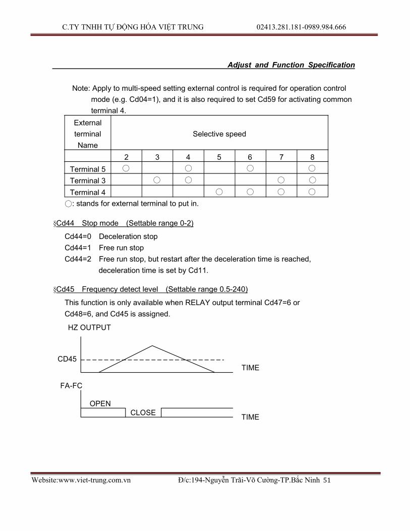
Note: Apply to multi-speed setting external control is required for operation control
mode (e.g. Cd04=1), and it is also required to set Cd59 for activating common
terminal 4.
External
terminal
Name
Selective speed
2 3 4 5 6 7 8
Terminal 5 ○ ○ ○ ○
Terminal 3 ○ ○ ○ ○
Terminal 4 ○ ○ ○ ○
○: stands for external terminal to put in.
§Cd44 Stop mode (Settable range 0-2)
Cd44=0 Deceleration stop
Cd44=1 Free run stop
Cd44=2 Free run stop, but restart after the deceleration time is reached,
deceleration time is set by Cd11.
§Cd45 Frequency detect level (Settable range 0.5-240)
This function is only available when RELAY output terminal Cd47=6 or
Cd48=6, and Cd45 is assigned.
HZ OUTPUT
CD45
FA-FC
TIME
OPEN
CLOSE TIME

C.TY TNHH TỰ ĐỘNG HÓA VIỆT TRUNG 02413.281.181-0989.984.666
Website:www.viet-trung.com.vn Đ/c:194-Nguyễn Trãi-Võ Cường-TP.Bắc Ninh 52
- 27 -

C.TY TNHH TỰ ĐỘNG HÓA VIỆT TRUNG 02413.281.181-0989.984.666
Website:www.viet-trung.com.vn Đ/c:194-Nguyễn Trãi-Võ Cường-TP.Bắc Ninh 53
Adjust and Function Specification
§ Cd46 Speed multiplier (Settable range 0.01-500)
The function shows revolution speed multiplied by a scaling factor on the Display.
Note:
1. HZ and A LED de-active.
2. RPM = Frequency ×Cd46
3. If the value overflow, it will show “9999”.
§Cd47 Relay 1 output select (Settable range 0-6)
The function sets the mode of relay1 to activate.
Cd47 Specification Remark
0 Time counter Time reached to the content of Cd29
1 Fault
2 Stop
3 Acceleration
4 Speed reached
5 Deceleration
6 Speed pass over Revolution frequency >content of Cd45
§Cd48 Relay 1 output select (Settable range 0-6)
The function sets the mode of relay2 to activate.
Cd47 Specification Remark
0 Time counter Time reached to the content of Cd29
1 Fault
2 Stop
3 Acceleration
4 Speed reached
5 Deceleration
6 Speed pass over Revolution frequency >content of Cd45
§Cd49 Function to lock data (Settable range 0, 1)
To lock data, prevent errors by none operator.
Cd49=0 Data change capable

C.TY TNHH TỰ ĐỘNG HÓA VIỆT TRUNG 02413.281.181-0989.984.666
Website:www.viet-trung.com.vn Đ/c:194-Nguyễn Trãi-Võ Cường-TP.Bắc Ninh 54
Cd49=1 Data change not capable
- 28 -

C.TY TNHH TỰ ĐỘNG HÓA VIỆT TRUNG 02413.281.181-0989.984.666
Website:www.viet-trung.com.vn Đ/c:194-Nguyễn Trãi-Võ Cường-TP.Bắc Ninh 55
Voltag
e O
utp
ut
Adjust and Function Specification
§Cd50 Software version (Read only)
This function is to record software version, read only.
§Cd51 Motor rated voltage setting Vr (Settable range 10-450)
This function cannot be modified during revolution.
RMS Setting
A. 220V Series: Value of Cd51 = Motor rated voltage / 1
B. 380V Series: Value of Cd51 = Motor rated voltage / 1.73
C. 460V Series: Value of Cd51 = Motor rated voltage / 2
Ex.
a. If the motor rated voltage 220Vrms. Power supply voltage 220Vrms, then setting
Cd51=220/1=220, then the inverter output Vrate=220Vrms.
b. If the motor rated voltage 380Vrms. Power supply voltage 380Vrms, then setting
Cd51=380/1.73=220, then the inverter output Vrate=380Vrms.
c. If the motor rated voltage 460Vrms. Power supply voltage 460Vrms, then setting
Cd51=460/2=230, then the inverter output Vrate=460Vrms.
V
Vr
(HZ)
Frequency Output
1. Vin >Vrate when Fr <Fb Vout = Fr / Fb ×Vrate
when Fr >Fb Vout = Vrate
2. Vin <Vrate when Vout <Vin Vout = Fr / Fb ×Vrate
when Vout >Vin Vout = Vin
Vin: Power supply voltage
Vout: Inverter output voltage
Vrate: Motor rated voltage
Fr: Inverter revolution frequency
Fb: base frequency
§Cd52 Motor no-load current setting (Settable range 5-60)

C.TY TNHH TỰ ĐỘNG HÓA VIỆT TRUNG 02413.281.181-0989.984.666
Website:www.viet-trung.com.vn Đ/c:194-Nguyễn Trãi-Võ Cường-TP.Bắc Ninh 56
This function cannot be modified during revolution.
The function is to compensate motor vibration during a light-load and fixed speed
revolution. This function must accommodate the content of Cd06.
- 29 -

C.TY TNHH TỰ ĐỘNG HÓA VIỆT TRUNG 02413.281.181-0989.984.666
Website:www.viet-trung.com.vn Đ/c:194-Nguyễn Trãi-Võ Cường-TP.Bắc Ninh 57
Adjust and Function Specification
Ex. Motor: 60Hz, 4-pole, 1 horsepower, 220V, no-load current 1.2Arms
Inverter: 1 horsepower, 220V, rated current 4.2Arms, Cd06=100
Cd52 = Motor no-load current / (Inverter rated current ×Motor rated
current ratio Cd06 ) ×100%
= 1.2 / (4.2 ×100%) ×100%
= 28.5%
§Cd53 Motor slip differential compensation (Settable range 0-100)
This function is to compensate speed variation produced by load variation.
This function must accommodate the content of Cd52.
Setting value 0-100 in relative slip differential 0.0-10.0%
Ex. 60HZ, 4-pole 1700 rpm
Synchronous speed = 1800 rpm
Full-load speed = 1700 rpm
Slip differential speed = 1800-1700=100 rpm
Slip differential % = Slip differential speed / Synchronous speed ×100%
= 100 / 1800 ×100%
= 5.5%, Setting Cd52=55
Slip differential compensation
Load variation
Time
Motor speed
Motor speed
Output
frequency
Without slip differential
compensation
With slip differential compensation
With slip differential compensation

C.TY TNHH TỰ ĐỘNG HÓA VIỆT TRUNG 02413.281.181-0989.984.666
Website:www.viet-trung.com.vn Đ/c:194-Nguyễn Trãi-Võ Cường-TP.Bắc Ninh 58
- 30 -
C.TY TNHH TỰ ĐỘNG HÓA VIỆT TRUNG 02413.281.181-0989.984.666
Website:www.viet-trung.com.vn Đ/c:194-Nguyễn Trãi-Võ Cường-TP.Bắc Ninh 59
Inve
rte
r cu
rrent
Fre
quen
cy
Inve
rte
r cu
rrent
Fre
quen
cy
Adjust and Function Specification
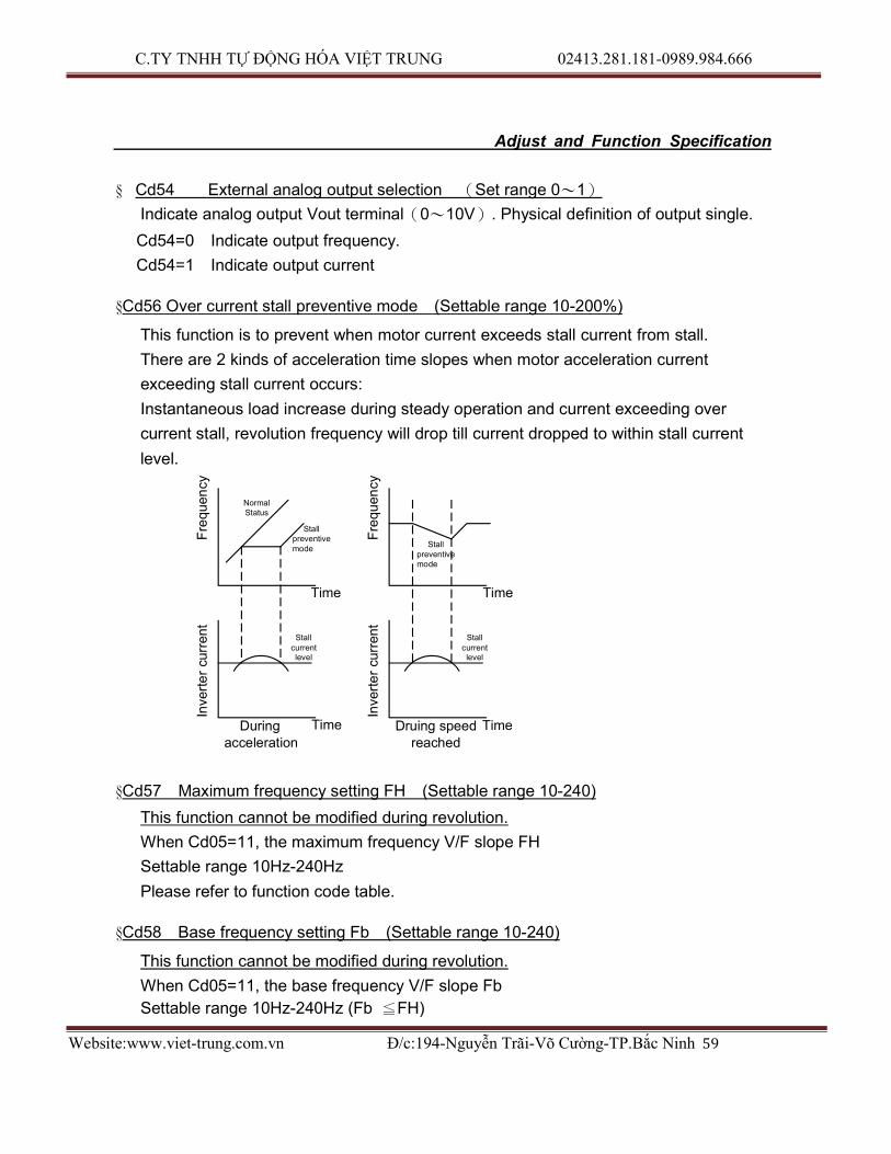
§ Cd54 External analog output selection (Set range 0〜1)
Indicate analog output Vout terminal(0〜10V). Physical definition of output single.
Cd54=0 Indicate output frequency.
Cd54=1 Indicate output current
§Cd56 Over current stall preventive mode (Settable range 10-200%)
This function is to prevent when motor current exceeds stall current from stall.
There are 2 kinds of acceleration time slopes when motor acceleration current
exceeding stall current occurs:
Instantaneous load increase during steady operation and current exceeding over
current stall, revolution frequency will drop till current dropped to within stall current
level.
Normal Status
Stall preventive mode
Stall preventive mode
Time Time
Stall
current level
Stall current level
During acceleration
Time Druing speed Time reached
§Cd57 Maximum frequency setting FH (Settable range 10-240)
This function cannot be modified during revolution.
When Cd05=11, the maximum frequency V/F slope FH
Settable range 10Hz-240Hz
Please refer to function code table.
§Cd58 Base frequency setting Fb (Settable range 10-240)
This function cannot be modified during revolution.
When Cd05=11, the base frequency V/F slope Fb
Settable range 10Hz-240Hz (Fb ≦FH)
C.TY TNHH TỰ ĐỘNG HÓA VIỆT TRUNG 02413.281.181-0989.984.666
Website:www.viet-trung.com.vn Đ/c:194-Nguyễn Trãi-Võ Cường-TP.Bắc Ninh 60
Please refer to function code table.
- 31 -

C.TY TNHH TỰ ĐỘNG HÓA VIỆT TRUNG 02413.281.181-0989.984.666
Website:www.viet-trung.com.vn Đ/c:194-Nguyễn Trãi-Võ Cường-TP.Bắc Ninh 61
Adjust and Function Specification
§Cd59 External terminal 4/6,3/5 function selection (Setting range 0-7)
This function is to select setting common terminal 3,4,5 and 6.
CD59 Common input terminal setting
DI4 DI6 DI3 DI5
0 JOG MBS 3DF 2DF
1 JOG/
Yards counter
RST 3DF/
Down speed %
2DF/
UP speed %
2 5DF MBS 3DF 2DF
3 5DF RST 3DF 2DF
4 JOG MBS DOWN UP
5 JOG RST DOWN UP
6 5DF MBS DOWN UP
7 5DF RST DOWN UP
Terminal specification: JOG: Jogging operation, accommodating with Cd15. 5DF: Multi-speed, accommodating with Cd4041, 42, 43 speed setting. MBS: Free run stop, operates both panel key and external signal. RST: Reset, operates both panel key and external signal 2DF: Second term operation, accommodating with Cd12 speed setting. 3DF: Third term operation, accommodating with Cd13 speed setting. UP: Using external terminal control on frequency increasing. Max. frequency is
setting of Cd00 DOWN: Using external terminal control on frequency decreasing. Min. frequency is
setting of Cd16
Note: when use multi-steps function, and Cd59=1, functions of external terminal 3,4,5
are listed as below:
Terminal 3: “Down Speed %”, means the speed will be decreased, according to
function CE37~CE45.
Terminal 4: Yards counter
Terminal 5: “Up Speed %”, means the speed will be decreased, according to
function CE37~CE45.

C.TY TNHH TỰ ĐỘNG HÓA VIỆT TRUNG 02413.281.181-0989.984.666
Website:www.viet-trung.com.vn Đ/c:194-Nguyễn Trãi-Võ Cường-TP.Bắc Ninh 62
- 32 -
C.TY TNHH TỰ ĐỘNG HÓA VIỆT TRUNG 02413.281.181-0989.984.666
Website:www.viet-trung.com.vn Đ/c:194-Nguyễn Trãi-Võ Cường-TP.Bắc Ninh 63
Outp
ut
Vo
ltage
Adjust and Function Specification
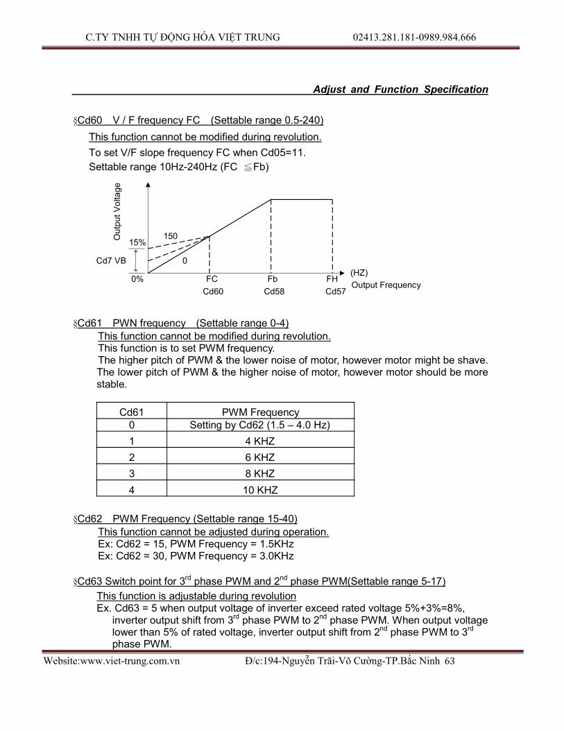
§Cd60 V / F frequency FC (Settable range 0.5-240)
This function cannot be modified during revolution.
To set V/F slope frequency FC when Cd05=11.
Settable range 10Hz-240Hz (FC ≦Fb)
15% 150
Cd7 VB
0%
0
FC Fb FH
Cd60 Cd58 Cd57
(HZ)
Output Frequency
§Cd61 PWN frequency (Settable range 0-4) This function cannot be modified during revolution. This function is to set PWM frequency. The higher pitch of PWM & the lower noise of motor, however motor might be shave. The lower pitch of PWM & the higher noise of motor, however motor should be more stable.
Cd61 PWM Frequency 0 Setting by Cd62 (1.5 – 4.0 Hz)
1 4 KHZ
2 6 KHZ
3 8 KHZ
4 10 KHZ
§Cd62 PWM Frequency (Settable range 15-40)
This function cannot be adjusted during operation. Ex: Cd62 = 15, PWM Frequency = 1.5KHz Ex: Cd62 = 30, PWM Frequency = 3.0KHz
§Cd63 Switch point for 3rd phase PWM and 2nd phase PWM(Settable range 5-17)
This function is adjustable during revolution Ex. Cd63 = 5 when output voltage of inverter exceed rated voltage 5%+3%=8%,
inverter output shift from 3rd phase PWM to 2nd phase PWM. When output voltage lower than 5% of rated voltage, inverter output shift from 2nd phase PWM to 3rd
phase PWM.

C.TY TNHH TỰ ĐỘNG HÓA VIỆT TRUNG 02413.281.181-0989.984.666
Website:www.viet-trung.com.vn Đ/c:194-Nguyễn Trãi-Võ Cường-TP.Bắc Ninh 64
Ex. Cd63 = 17 when inverter output voltage exceed rated voltage 17%+3% =20%, inverter output shift from 3rd phase PWM to 2nd phase PWM. When output voltage lower than 17% of rated voltage, inverter output shift from 2nd phase PWM to 3rd
phase PWM.
- 33 -
C.TY TNHH TỰ ĐỘNG HÓA VIỆT TRUNG 02413.281.181-0989.984.666
Website:www.viet-trung.com.vn Đ/c:194-Nguyễn Trãi-Võ Cường-TP.Bắc Ninh 65
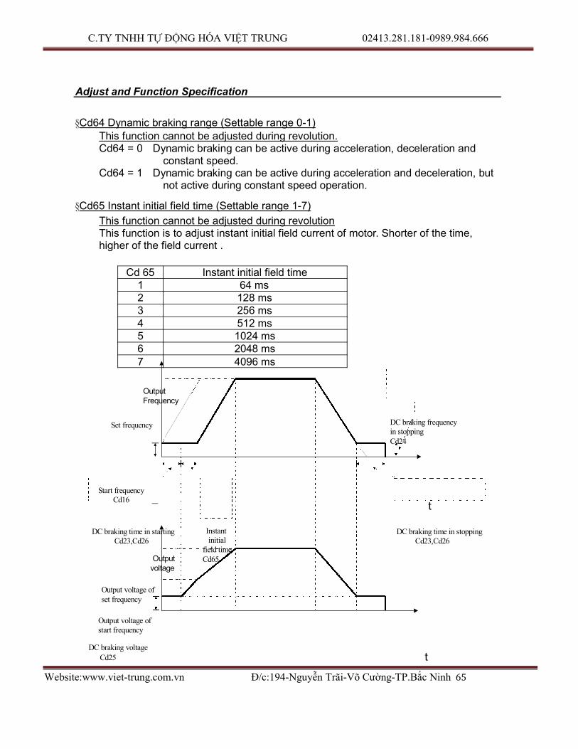
Adjust and Function Specification
§Cd64 Dynamic braking range (Settable range 0-1) This function cannot be adjusted during revolution. Cd64 = 0 Dynamic braking can be active during acceleration, deceleration and
constant speed. Cd64 = 1 Dynamic braking can be active during acceleration and deceleration, but
not active during constant speed operation.
§Cd65 Instant initial field time (Settable range 1-7)
This function cannot be adjusted during revolution This function is to adjust instant initial field current of motor. Shorter of the time, higher of the field current .
Cd 65 Instant initial field time 1 64 ms 2 128 ms 3 256 ms 4 512 ms 5 1024 ms 6 2048 ms 7 4096 ms
Output Frequency
Set frequency DC braking frequency
in stopping Cd24
Start frequency Cd16
t
DC braking time in starting
Cd23,Cd26
Output voltage
Instant initial
field time Cd65
DC braking time in stopping Cd23,Cd26
Output voltage of set frequency
Output voltage of start frequency
DC braking voltage
Cd25 t
C.TY TNHH TỰ ĐỘNG HÓA VIỆT TRUNG 02413.281.181-0989.984.666
Website:www.viet-trung.com.vn Đ/c:194-Nguyễn Trãi-Võ Cường-TP.Bắc Ninh 66
- 34 -

C.TY TNHH TỰ ĐỘNG HÓA VIỆT TRUNG 02413.281.181-0989.984.666
Website:www.viet-trung.com.vn Đ/c:194-Nguyễn Trãi-Võ Cường-TP.Bắc Ninh 67
Adjust and Function Specification
§Cd66 Digital filter function (Settable range 1-6) This function is adjustable during revolution This is function is active as digital filter while invert with external analogue input. Increasing the figure to stabilized frequency while noise of external analogue input is higher. Decrease the figure when inverter required to response faster.
Cd 66 Digital filter time
1 4 ms 2 8 ms 3 16 ms 4 32 ms 5 64 ms 6 128 ms
§Cd67 Power source positioning accuracy calibration (Settable range 0-20)
This function is adjustable during revolution This function is to adjust the calibration of voltage positioning on DC BUS between detected and actual position. The display value of Cd02=3 will be lower when Cd67 set at bigger figure. Cd02=3 display will be higher when Cd67 setting at smaller figure.
§Cd68 Dead Time compensation adjustment (Settable range 0-10)
This function cannot be adjusted during revolution This function is to compensate characteristic differential of IC. Therefore, it should be adjusted in accordance with individual power IC. Motor would be vibrating if this function did not adjust properly. This function has been properly adjusted before ex-factory. Recommend customer not to adjust. If adjustment required, start from “5”, either increase or decrease to a figure that motor operation at the most stable operation.
§ Cd70 Dynamic Braking active level (Settable range 120~140)
This function cannot be modified during revolution This function is to adjust active point of dynamic braking. Note : 220V series: protection point voltage (VDC)= Cd70 ×200V ×% ×√2
400V series: protection point voltage (VDC)= Cd70 ×400V ×% ×√2
§ Cd71 Over Voltage prevention function active point (Settable range 130~145)
This function cannot be modified during revolution This is to adjust the over voltage protection active point when over voltage occurred. Note:
220Vseries:active voltage (VDC)= setting value ×200V ×% ×√2
400Vseries:active voltage (VDC)= setting value ×400V ×% ×√2

C.TY TNHH TỰ ĐỘNG HÓA VIỆT TRUNG 02413.281.181-0989.984.666
Website:www.viet-trung.com.vn Đ/c:194-Nguyễn Trãi-Võ Cường-TP.Bắc Ninh 68
- 35 -

C.TY TNHH TỰ ĐỘNG HÓA VIỆT TRUNG 02413.281.181-0989.984.666
Website:www.viet-trung.com.vn Đ/c:194-Nguyễn Trãi-Võ Cường-TP.Bắc Ninh 69
Adjust and Function Specification
§ Cd77 KW-Hour and MW-Hour reset memory (setting range 0~1)
When set Cd79=1, KW-Hour and MW-Hour will be recorded automatically when the
power off. When set up successfully, “CLr” will showed, and the record will be cleared
to zero.
§ Cd79 auto saving function setting (setting range 0~1)
This function can’t be modified during revolution. Cd79=0 Disable auto saving Cd79=1 Enable auto saving. When power off KW-Hour, MW-Hour, Hanks counter,
Current time of PLC and current step PLC will be recorded automatically.
§ Cd80 Modbus Protocol and communication mode setting (settable range 0-6)
This function can’t be modified during revolution. Selection of operation method on RS485 communication port. Supporting Modbus Protocol. Cd80=0 RS485 shut down communication interface. Cd80=1 Active RTU Mode. Parameter change is not allowed. Cd80=2 Active RTU Mode. Allow changes on general parameter. Cd80=3 Active RTU Mode. Allow changes on operation instruction and general parameter. Cd80=4 active ASCII Mode. Parameter change is not allowed.)
Cd80=5 active ASCII Mode. Allow changes on general parameter.)
Cd80=6 active ASCII Mode. Allow changes on operation instruction and general parameter.)
§ Cd81 RS485 communication address setting (settable range 1-240)
This function can not be modified during revolution Corresponding communication address should be set in advance when active RS485 communication function. Inverter is at slave side. Note: Communication function refers to manuals of interface.
§ Cd82 Series communication baud rate setting (settable range 0-3)
This function can’t be modified during revolution. Setting of Baud rate during communication Cd82=0 2400 bps Cd82=1 4800 bps Cd82=2 9600 bps Cd82=3 19200 bps Note: Re-start inverter after setting Baud rate.
§ Cd83 Series communication response time setting(settable range 0-15)
This function can’t be modified during revolution. Setting waiting time for response when inverter receive correction data. MODBUS RESPONE TIME=(0 ~ 8ms) + (8ms * CD83)

C.TY TNHH TỰ ĐỘNG HÓA VIỆT TRUNG 02413.281.181-0989.984.666
Website:www.viet-trung.com.vn Đ/c:194-Nguyễn Trãi-Võ Cường-TP.Bắc Ninh 70
- 36 -
C.TY TNHH TỰ ĐỘNG HÓA VIỆT TRUNG 02413.281.181-0989.984.666
Website:www.viet-trung.com.vn Đ/c:194-Nguyễn Trãi-Võ Cường-TP.Bắc Ninh 71
Adjust and Function Specification
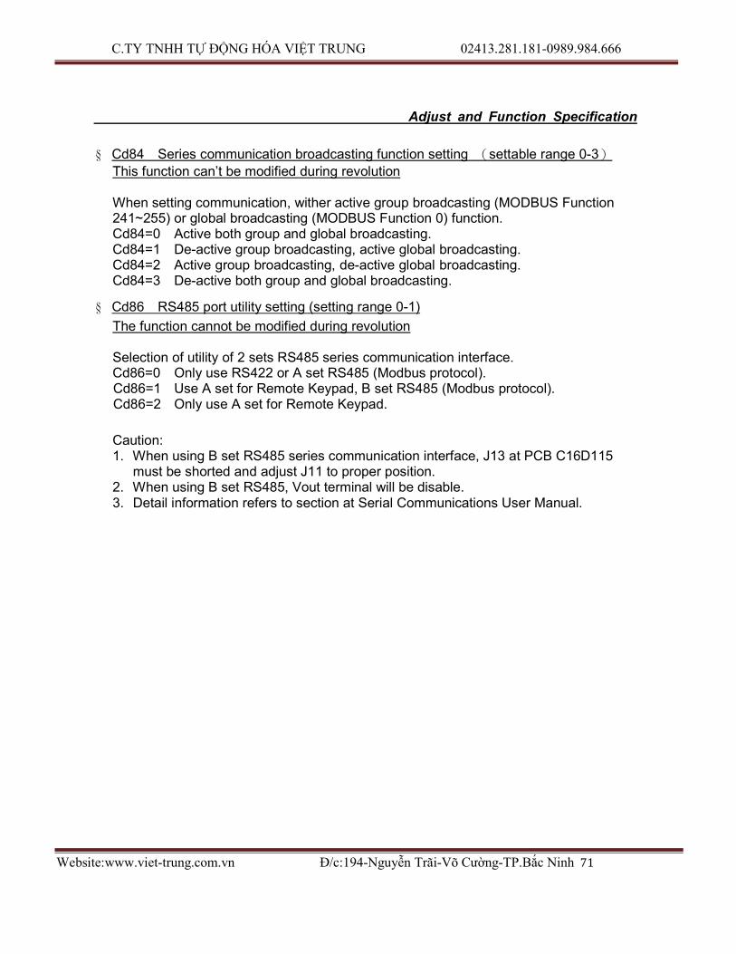
§ Cd84 Series communication broadcasting function setting (settable range 0-3)
This function can’t be modified during revolution
When setting communication, wither active group broadcasting (MODBUS Function 241~255) or global broadcasting (MODBUS Function 0) function. Cd84=0 Active both group and global broadcasting. Cd84=1 De-active group broadcasting, active global broadcasting. Cd84=2 Active group broadcasting, de-active global broadcasting. Cd84=3 De-active both group and global broadcasting.
§ Cd86 RS485 port utility setting (setting range 0-1)
The function cannot be modified during revolution
Selection of utility of 2 sets RS485 series communication interface. Cd86=0 Only use RS422 or A set RS485 (Modbus protocol). Cd86=1 Use A set for Remote Keypad, B set RS485 (Modbus protocol). Cd86=2 Only use A set for Remote Keypad.
Caution: 1. When using B set RS485 series communication interface, J13 at PCB C16D115
must be shorted and adjust J11 to proper position. 2. When using B set RS485, Vout terminal will be disable. 3. Detail information refers to section at Serial Communications User Manual.

C.TY TNHH TỰ ĐỘNG HÓA VIỆT TRUNG 02413.281.181-0989.984.666
Website:www.viet-trung.com.vn Đ/c:194-Nguyễn Trãi-Võ Cường-TP.Bắc Ninh 72
- 37 -

C.TY TNHH TỰ ĐỘNG HÓA VIỆT TRUNG 02413.281.181-0989.984.666
Website:www.viet-trung.com.vn Đ/c:194-Nguyễn Trãi-Võ Cường-TP.Bắc Ninh 73
Adjust and Function Specification
§CE00,01,02,03 Failure record
Record cause of failure, in order to solve failure.
Note:1.Cannot record failure Err, Ero, Erc.
2.Only memorize 4 records.
3.Cannot record inverter stopped by low voltage.
4.Read only Cd00,01,02,03 or delete all (Code 36), cannot put in failure record by
operator.
§ CE11 - CE20 Multi-step function control frequency setting(settable range
0.5-240HZ)
Maximum 10 steps. CE11 1st step speed setting CE12 2nd step speed setting CE13 3rd step speed setting CE14 4th step speed setting CE15 5th step speed setting CE16 6th step speed setting CE17 7th step speed setting CE18 8th step speed setting CE19 9th step speed setting CE20 10th step speed setting
§ CE21 - CE36 Multi-step process control time setting(settable range 0 - 100Min)
Maximum 10 steps. End of entire procedure if time setting = 0. CE21 1st step time setting CE22 2nd step time setting CE23 3rd step time setting CE24 4th step time setting CE25 5th step time setting CE26 6th step time setting CE27 7th step time setting CE28 8th step time setting CE29 9th step time setting CE30 10th step time setting
§ CE37 1st frequency increase setting (setting range 0.0~10.0%)
(1st Bob up speed %)
Set the 1st frequency increase percentage. The setting is related with current working
speed of inverter.
When Inverter working under multi-step function mode(Cd01=7), and CE47=2, or 3,
Cd59=1, short terminal 5(UP) and COM, then the speed will be
C.TY TNHH TỰ ĐỘNG HÓA VIỆT TRUNG 02413.281.181-0989.984.666
Website:www.viet-trung.com.vn Đ/c:194-Nguyễn Trãi-Võ Cường-TP.Bắc Ninh 74
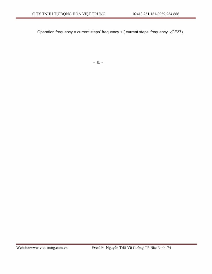
Operation frequency = current steps’ frequency + ( current steps’ frequency ×CE37)
- 38 -
C.TY TNHH TỰ ĐỘNG HÓA VIỆT TRUNG 02413.281.181-0989.984.666
Website:www.viet-trung.com.vn Đ/c:194-Nguyễn Trãi-Võ Cường-TP.Bắc Ninh 75
Adjust and Function Specification
§ CE38 2nd frequency increase setting (setting range 0.0~10.0%)
(2nd Bob up speed %)
Set the 2nd frequency increase percentage.
§ CE39 3rd frequency increase setting (setting range 0.0~10.0%)
(3rd Bob up speed %)
Set the 3rd frequency increase percentage.
§ CE40 Setting Times of 1st frequency increase (setting range0〜200min )
(1st Bob up speed % time)
Set the time of 1st frequency increase percentage.
When multi-step operation time shorter than CE40, CE37 will be the current frequency
increase order. If CE40=0 it will use CE37 as frequency increase order, no matter what
is the perform time in multi-step function.
§ CE41 Setting Times of 2nd frequency increase (setting range0〜200min )
(2nd Bob up speed % time)
Set the time of 2nd frequency increase percentage. When multi-step function operation time longer than CE40 and shorter than CE41, the frequency will increased as CE38. If CE41=0 it will use CE38 as frequency increase order, no matter what is the perform time in multi-step function.
When multi-step operation time is longer or equal to CE41, it will use CE39 as current
frequency increase order.
§ CE42 1st frequency decrease setting (Setting range 0.0~10.0%)
(1st Bob down speed %)
Set the 1st frequency decrease percentage. The setting is related with current working
speed of inverter. When inverter working under multi-steps function mode(Cd01=7),
and CE47=2, or 3、Cd59=1, short external terminal 3(DOWN) and COM, then the
speed will be
Operation frequency = current steps’ frequency – (current steps’ frequency ×CE42)
§ CE43 2nd frequency decrease setting (Setting range 0.0~10.0%)
(2nd Bob down speed %)
Set the second frequency decrease percentage.
§ CE44 3rd frequency decrease setting (Setting range 0.0~10.0%)
C.TY TNHH TỰ ĐỘNG HÓA VIỆT TRUNG 02413.281.181-0989.984.666
Website:www.viet-trung.com.vn Đ/c:194-Nguyễn Trãi-Võ Cường-TP.Bắc Ninh 76
(3rd Bob down speed %)
Set the third step frequency decrease percentage.
- 39 -

C.TY TNHH TỰ ĐỘNG HÓA VIỆT TRUNG 02413.281.181-0989.984.666
Website:www.viet-trung.com.vn Đ/c:194-Nguyễn Trãi-Võ Cường-TP.Bắc Ninh 77
Adjust and Function Specification
§ CE45 Setting Times of 1st frequency decrease (setting range 0~200min)
(1st Bob down speed % time)
Set the time of 1st frequency decrease percentage. When multi-steps operation time shorter than CE45, CE42 will be the current frequency decrease order.
If CE45=0 it will use CE42 as frequency decrease order, no matter what is the time of
the perform time in multi-step function.
§ CE46 Setting Times of 2nd frequency decrease (setting range 0~200min)
(2nd Bob down speed % time)
Set the time of 2nd frequency decrease percentage. When multi-steps operation time longer than CE45 and shorter than CE46, the frequency will decrease as CE43.
If CE46=0 it will use CE43 as frequency decrease order, no matter what is the perform
time in multi-step function. When multi- steps operation time longer or equal to CE46, it
will use CE44 as current frequency decrease order.
§ CE47 Multi steps function modes selection(settable range0〜1)
The function cannot be modified during revolution Select operation modes on speed variation when process control switch from previous step to next step. CE47=0 Liner operation CE47=1 Gradually operation. (Perform time can set to zero, when perform time set to 0,
perform time will according to CD08, CD09 increase or decrease. If the step frequency set to 0, the step will be ended.)
CE47=2 Liner operation use Up/Down Speed % function.
CE47=3 Gradually operation use Up/Down Speed % function. (Perform time can set to
zero, when perform time set to 0, acceleration/deceleration time will according
to CD08, CD09. If the steps’ frequency set to 0, the step will be ended.)
Liner operation
O u tput frequen c y
C E 1 6
C E 1 5
C E 1 4
CE 1 3
CE 1 2
CE 1 1 CE 0 8 CE 0 9

C.TY TNHH TỰ ĐỘNG HÓA VIỆT TRUNG 02413.281.181-0989.984.666
Website:www.viet-trung.com.vn Đ/c:194-Nguyễn Trãi-Võ Cường-TP.Bắc Ninh 78
CE
2 1
C
E 2
2
CE
2 3
C
E 2
4
CE
2 5
C
E 2
6
CE
2 7
C
E 2
8
CE
2 9
C
E 3
0
CE 1 7
CE 1 8
CE 1 9
CE 2 0
t
- 40 -

C.TY TNHH TỰ ĐỘNG HÓA VIỆT TRUNG 02413.281.181-0989.984.666
Website:www.viet-trung.com.vn Đ/c:194-Nguyễn Trãi-Võ Cường-TP.Bắc Ninh 79
CE
2 1
C
E 2
2
CE
2 3
C
E 2
4
CE
2 5
C
E 2
6
CE
2 7
C
E 2
8
CE
2 9
C
E 3
0
Adjust and Function Specification
Gradually operation
O u tp ut frequen cy
CE 1 6 CE 1 5
CE 1 4
CE 1 3
CE 1 2 CE 1 1
CE 1 7 CE 1 8
CE 1 9 CE 2 0
t
CE 0 9
Up/Down Speed %
function
Frequency
CE38 CE39 CE37
Output freq. CE44 CE42 CE43
CE08 CE09
CE40
CE45 CE46 CE41 t
UP
DOWN t
§ CE48 Multi steps function operation reset (settable range0〜1)
The function cannot be modified during revolution Memorized of current operation step and time (in sec) while shut down or power failure. Step and time reset to 0 when set CE48=1.
Note: External terminal 6 set to RST function, when RST connect with COM, it will reset
the records and steps time to 0.

C.TY TNHH TỰ ĐỘNG HÓA VIỆT TRUNG 02413.281.181-0989.984.666
Website:www.viet-trung.com.vn Đ/c:194-Nguyễn Trãi-Võ Cường-TP.Bắc Ninh 80
- 41 -

C.TY TNHH TỰ ĐỘNG HÓA VIỆT TRUNG 02413.281.181-0989.984.666
Website:www.viet-trung.com.vn Đ/c:194-Nguyễn Trãi-Võ Cường-TP.Bắc Ninh 81
Adjust and Function Specification
§ CE49 Multi steps process control continuous operation (settable range0〜1)
The function cannot be modified during revolution Selection of shut down or start from 1st step while entire operation procedure finished. CE49=0 Not continuous operation. CE49=1 Continuous operation. From 1st steps’ speed continuous operation.
CE49=2 Continuous operation, perform speed as the last speed in the step, till the
RST or CE48 set to1, then change to first step’s speed.
Not continuous
operation
Frequency
last step
First step
Continuous
operation
frequency
t
From 1st step speed continuous operation.
last step
First step
t
Continuous
operation, perform
speed as the last
speed in the step,
till the RST or
CE48 set to1
frequency
Last step
First step
Perform speed as the last speed in the step,
till the RST or CE48 set to 1, then change to first step’s speed to continuous operation
t
§CE52 Choice of multi-speed record file (settable range 1~6)

C.TY TNHH TỰ ĐỘNG HÓA VIỆT TRUNG 02413.281.181-0989.984.666
Website:www.viet-trung.com.vn Đ/c:194-Nguyễn Trãi-Võ Cường-TP.Bắc Ninh 82
The function cannot be modified during revolution
The setting cannot be changed while the machine is working. According to the needs of the user, choose different file for the current step, the data CE05~CE46 are stored in the files.
- 42 -

C.TY TNHH TỰ ĐỘNG HÓA VIỆT TRUNG 02413.281.181-0989.984.666
Website:www.viet-trung.com.vn Đ/c:194-Nguyễn Trãi-Võ Cường-TP.Bắc Ninh 83
Adjust and Function Specification
§ CE53 Multi-steps all files set to default (settable range 0~1)
The function cannot be modified during revolution
The setting can not be changed while the machine is working.
CE53=0 Data remain unchanged.
CE53=1 Reset data in files 1-6 to default.
§ CE54 Multi-steps memory duplicate function (settable range 1~6)
The function cannot be modified during revolution
The setting cannot be changed while the machine is working.
Duplicate current using file (CE05~CE46) to CE54 .
§ CE55 Yards counter clear (settable range 0~1)
Set CE55=1 to clear Yards counter.
§ CE61 Input terminal for Set Point and PI feedback (settable range 0~7)
The function cannot be modified during revolution
CE61 Target value PI feedback terminal
0 De-active PI control
1 Set by CE67 IN1
2 Set by CE67 IN2
3 Set by CE67 IN3
4 From terminal IN1 IN2
5 From terminal IN1 IN3
6 From terminal IN3 IN1
7 From terminal IN3 IN2
Note:
1. IN1(4~20mA) scale to 0~100.0 %, IN2、IN3(0~10V) scale to 0~100.0 %
2. output frequency = PI output frequency + set frequency
3. Make sure this parameter setting does not conflict with the setting for Cd01
(Set frequency source).
Ex: If Cd01=1 then the parameter CE61 cann’t be modify to 2 ,4 or 7.

C.TY TNHH TỰ ĐỘNG HÓA VIỆT TRUNG 02413.281.181-0989.984.666
Website:www.viet-trung.com.vn Đ/c:194-Nguyễn Trãi-Võ Cường-TP.Bắc Ninh 84
- 43 -

C.TY TNHH TỰ ĐỘNG HÓA VIỆT TRUNG 02413.281.181-0989.984.666
Website:www.viet-trung.com.vn Đ/c:194-Nguyễn Trãi-Võ Cường-TP.Bắc Ninh 85
Adjust and Function Specification
Bottom freq.
Cd58
CE67
IN1
IN3
CE61
+ P + _
CE62
I CE63
IN1
IN2
Output limit
+ CE65
PI Output freq.
IN3
§ CE62 Proportion gain (settable range 0~10.0)
This parameter specifies proportional control and associated gain (P).
§ CE63 Integral gain (settable range 0.2~1000.0 sec)
This parameter specifies integral control (continual sum of the deviation) and associated gain (I).
§ CE65 PI output limit setting (settable 0~100 %)
This parameter defines the percentage of output limit during the PID control.
§ CE67 PI control target value 1 (settable 0~100.0 %)
This parameter defines the percentage of target value.

C.TY TNHH TỰ ĐỘNG HÓA VIỆT TRUNG 02413.281.181-0989.984.666
Website:www.viet-trung.com.vn Đ/c:194-Nguyễn Trãi-Võ Cường-TP.Bắc Ninh 86
- 44 -

C.TY TNHH TỰ ĐỘNG HÓA VIỆT TRUNG 02413.281.181-0989.984.666
Website:www.viet-trung.com.vn Đ/c:194-Nguyễn Trãi-Võ Cường-TP.Bắc Ninh 87
Description of alarm display indications 7. Description of alarm display indications
Error indication
Description of fault operation
Item for inspection Processing
Err Operation error Was the unit operated as indicated in the manual
Use the correct procedure
ErO Operation error of Switch off the power and then Replace the unit
internal ROM,
RAM
ErC Error of internal
CPU
apply again
Is there a large amount of external noise
Check the contact absorber. Install a noise
filter
OCPA Over current (180% rated
current)
OCPd Over current (180% rated current)
OCPn Over current
Was there rapid acceleration Lengthen the acceleration time
Was there rapid deceleration Lengthen the deceleration time
Was there any variation in the Lengthen the time for the
(180% rated current)
OC Over current (200% rated current)
OCS Output short circuit or ground
detected
OU DC link over voltage
LU Insufficient voltage detected
due to power failure or
instantaneous power loss.
LU A Insufficient voltage detected
due to power failure or instantaneous
power loss. And
the auto save function is
working
load
Was there rapid acceleration / deceleration and variation in the load
Is there a short circuit for the
output or grounding for the motor
Was there fast deceleration, or fast voltage
Is there a low voltage at power, or internal inverter wiring error
Is there a low voltage at
power, or internal inverter wiring error

C.TY TNHH TỰ ĐỘNG HÓA VIỆT TRUNG 02413.281.181-0989.984.666
Website:www.viet-trung.com.vn Đ/c:194-Nguyễn Trãi-Võ Cường-TP.Bắc Ninh 88
load variations
Lengthen the acceleration and deceleration time and reduce the load
Perform a megger check
for the motor
Lengthen the deceleration time. Investigate the use of the optional DBR
Improve the voltage condition and confirm inverter model
Improve the voltage
condition and confirm inverter model
- 45 -

C.TY TNHH TỰ ĐỘNG HÓA VIỆT TRUNG 02413.281.181-0989.984.666
Website:www.viet-trung.com.vn Đ/c:194-Nguyễn Trãi-Võ Cường-TP.Bắc Ninh 89
Description of alarm display indications
Error indication
Description of fault operation
Item for inspection Processing
OH Overheating of the cooling fan detected
1. Cooling fan stops 2. Ambient temperature too
hot
3. Motor being overload
1. Exchange the cooling fan
2. Lower the ambient temperature
3. Check the load conditions
OL Overload detected for more
than one minute
OL A Overload
warning, the
motor is nearly
1min, 150%
overload.
Is the motor being overloaded Increase the capacity of the inverter and motor
Is the motor being overloaded Increase the capacity of the inverter and motor
bUOH DBR overheat detected
ES Emergency switch active
Is the braking ratio appropriate
Check if DI6 and COM are open.
Reduce GD2 of load or lengthen deceleration time
Short DI6 and COM
Fb Fuse blown Is the fuse blown Change a fuse
PLU Power voltage too Is power voltage too low Improve power supply
low condition

C.TY TNHH TỰ ĐỘNG HÓA VIỆT TRUNG 02413.281.181-0989.984.666
Website:www.viet-trung.com.vn Đ/c:194-Nguyễn Trãi-Võ Cường-TP.Bắc Ninh 90
- 46 -

C.TY TNHH TỰ ĐỘNG HÓA VIỆT TRUNG 02413.281.181-0989.984.666
Website:www.viet-trung.com.vn Đ/c:194-Nguyễn Trãi-Võ Cường-TP.Bắc Ninh 91
Troubleshooting
8. Troubleshooting
Description of trouble Possible cause Solution
The motor does not
run at all
“OCPA” is indicated
1. Wiring error Refer to the wiring diagram
1. Check the power input wiring
2. Is there a voltage for U.V.W output
2. Wrong settings at operator panel The function code No.04 is as follows
0: Panel key operation
1: External signals
3. Inverter displays fault indication Refer to “Protect Function”
4. Motor cannot start due to overload Exchange a higher capacity one
5. Motor breaks down Repair motor
6. Inverter breaks down Please contact us
1. Motor wiring error Refer to the wiring diagram
as soon as the motor 2. Overload Reduce the load or increase inverter
is started.
capacity
(Overcurrent protects 3. Is V/F slope appropriate Check Code 05 V/F slope is appropriate
operation during
acceleration.)
with motor specification
4. Is start torque appropriate Adjust Code 07 torque boost to over come
steady friction but not over current trip.
5. Is the acceleration time too short
when compared to load GD2
6. The inverter is starting during
motor free-run
Lengthen acceleration time by apply Code
08 and Code 10 or increase inverter
capacity
Refers to Code 28, change the value from 0
to 1
“OCPd” is indicated
1. Deceleration time too short, unable Apply Code 09 and Code 11 to lengthen
as the motor is
decelerating. (Over
current protects
operation during
deceleration).
“OC” or “OCS” is
indicated during
operation. (Over
current)
to be loaded 1. Short circuit on U.V.W or
grounding for motor
2. Instantaneously mechanical load
on motor
deceleration time or increase inverter
capacity
Exclude short circuit or grounding
Reduce load or increase inverter capacity

C.TY TNHH TỰ ĐỘNG HÓA VIỆT TRUNG 02413.281.181-0989.984.666
Website:www.viet-trung.com.vn Đ/c:194-Nguyễn Trãi-Võ Cường-TP.Bắc Ninh 92
3. Motor breaks down Repair motor
4. Inverter breaks down Please contact us
- 47 -

C.TY TNHH TỰ ĐỘNG HÓA VIỆT TRUNG 02413.281.181-0989.984.666
Website:www.viet-trung.com.vn Đ/c:194-Nguyễn Trãi-Võ Cường-TP.Bắc Ninh 93
Troubleshooting
Description of trouble Possible cause Solution
“OU” is displayed
during inverter
1. Is power voltage with the
specification
Improve power voltage condition
operation
2. Braking resistor not applied Apply braking resistor, increase braking
ratio
3. Deceleration time too short, unable Apply Code 09 and Code 11 to lengthen
“PLU” is displayed
during inverter
operation
to be loaded
1. Is power voltage with the
specification
2. Instantaneous power voltage
failure
3. Power dropped and the protector
function has operated
deceleration time
Improve power voltage condition
Check the capacity of the power facilities
Check the capacity of the power facilities
“OL” is displayed
1. Overload Reduce load or increase inverter capacity
during inverter
operation
“OH” is displayed
during inverter
2. Is inverter over current limiter
appropriate
1. Check if the cooling fan is still
working
Apply Code 06 to re-set motor rated current
Change cooling fan and clean dirt
operation 2. Is ambient temperature too hot Improve ambient temperature condition
No any indication,
1. Power failure Check the capacity of the power facilities
the output frequency
displayed “0”
2. Is there loosen part on external
control terminal
Check external control terminal

C.TY TNHH TỰ ĐỘNG HÓA VIỆT TRUNG 02413.281.181-0989.984.666
Website:www.viet-trung.com.vn Đ/c:194-Nguyễn Trãi-Võ Cường-TP.Bắc Ninh 94
- 48 -

C.TY TNHH TỰ ĐỘNG HÓA VIỆT TRUNG 02413.281.181-0989.984.666
Website:www.viet-trung.com.vn Đ/c:194-Nguyễn Trãi-Võ Cường-TP.Bắc Ninh 95
Maintenance and Inspection 9. Maintenance and Inspection
Maintenance and inspection must be taken under power off.
Cautions on maintenance and inspection:
(1) Capacitor is charged at high voltage for a while after turning off the power.
(Accordingly, start the inspection work at least 5 minutes after turning off the
power)
(2) Do the work with operator.
Inspection items:
(1) Please check the following items
A. Motor runs as expected.
B. Avoid installing on circumstances like acid, alkaloid.
C. No trouble is recognized in the cooling system and irregular vibration or
noise.
D. No parts is overheated or burned.
(2) Periodic inspection
Interval Inspection item
Every 6 months 1. Terminal plates and mounting bolts.
2. Corrosion and breaks in the terminal clips for
the wiring.
3. Condition for the connector fixing.
Once a year 1. Use clean, dry air to remove dust buildup from
the guards, the stack and the cooling fan.
2. Check for parts burns or damage and make
any exchanges necessary.

C.TY TNHH TỰ ĐỘNG HÓA VIỆT TRUNG 02413.281.181-0989.984.666
Website:www.viet-trung.com.vn Đ/c:194-Nguyễn Trãi-Võ Cường-TP.Bắc Ninh 96
- 49 -

C.TY TNHH TỰ ĐỘNG HÓA VIỆT TRUNG 02413.281.181-0989.984.666
Website:www.viet-trung.com.vn Đ/c:194-Nguyễn Trãi-Võ Cường-TP.Bắc Ninh 97
Standard Specification
10. Standard Specification
A. 200Vseries
Motor rating (KW) 2.2 3.7 5.5 7.5 11 15 22 30 37 45 55 75 93
Model
CT2002F- 2A2 3A7 5A5 7A5 011 015 022 030 037 045 055 075 093
Rated current (A) 11.1 18 23 33 48 61 86 125 150 170 210 278 330
Rated capacity (KVA)
4.4 7.1 9.2 13.1 19.1 24.3 34.3 49 60 68 84 111 131
Power supply 3∮ 200~230V ±10% 50HZ ±5% or
3∮ 200~230V ±10% 60HZ ±5%
Output voltage 3∮ 200V、220V、230V
Cooling system Forced air-cooling
Outline dimension Fig1 Fig1 Fig1 Fig2 Fig2 Fig2 Fig2 Fig2 Fig2 Fig2 Fig2 Fig2 Fig2
Weight (Kg) 8 8 9 14 14 20 30 45 60 60 65 70 70
B. 400Vseries
Motor rating (KW) 2.2 3.7 5.5 7.5 11 15 22 30 37 45 55 75 93 112
Model
CT2004F- 2A2 3A7 5A5 7A5 011 015 022 030 037 045 055 075 093 112
Rated current (A) 6.2 9 13 17.3 24 31 52 65 71 93 110 156 180 225
Rated capacity (KVA)
4.9 7.1 10.4 13.8 19.1 24.7 41.4 51.8 56.6 74 87.6 124 143 180
Power supply 3∮ 380~460V ±10% 50HZ ±5% or
3∮ 380~460V ±10% 60HZ ±5%
Output voltage 3∮ 380V、400V、440V、460V
Cooling system Forced air-cooling
Outline dimension Fig1 Fig1 Fig1 Fig2 Fig2 Fig2 Fig2 Fig2 Fig2 Fig2 Fig2 Fig2 Fig2 Fig2
Weight (Kg) 8 9 9 14 14 18 35 38 40 46 50 65 70 70

C.TY TNHH TỰ ĐỘNG HÓA VIỆT TRUNG 02413.281.181-0989.984.666
Website:www.viet-trung.com.vn Đ/c:194-Nguyễn Trãi-Võ Cường-TP.Bắc Ninh 98
- 50 -

C.TY TNHH TỰ ĐỘNG HÓA VIỆT TRUNG 02413.281.181-0989.984.666
Website:www.viet-trung.com.vn Đ/c:194-Nguyễn Trãi-Võ Cường-TP.Bắc Ninh 99
Standard Specification
C.Standard specification
Control method Sine P.W.M control
Frequency accuracy
Frequency resolution
Digital setting: ±0.1% Analog setting: ±0.5% (35℃) Digital setting: 0.5〜100Hz→0.01Hz 100Hz〜240Hz→0.1Hz
Analog setting: (setting value/1000)Hz
Frequency range 0.5〜240HZ(Initial frequency 0.5〜30Hz)
V/F ratio 10 patterns, or any V/F patterns.
Torque boost 0〜15.0% voltage boost, automatic voltage boost
Acceleration / Deceleration time
0.1〜6000 sec(linear, two-step setting)
Motor Braking 100% DB. Under 3.7KW Including braking resister.
20% DB. Connect extra braking resister to reach 100% DB.
DC Braking DC Injection Braking(Setting mode, torque, time, active frequency)
Standard feature Free run restart, jogging speed, upper/lower frequency limit setting, jump frequency setting, 8-step speed setting, frequency increase/decrease (UP/DOWN) function, BIAS, frequency indicated output (DC0〜10V), operation direction setting, forward/reverse
prohibit, voltage/current limit, data lock, multi-step function, auto record when power off, 6 memory pattern of multi-step function.
Frequency setting Digital setting by keypad, or external analog signal(DC0〜10V,DC4
〜20mA)
Display 7-segment LED display: Frequency, current, voltage, setting value, function, fault status, Temperature of PIM module, status of multi-step function, average speed of multi-step function, instant power, power factor, Kwh, Mwh.
Protection Low voltage, over voltage, instantaneous power failure, over voltage stall, overload, over current stall, instantaneous over current, acceleration over current, deceleration over current, over heat.
Overload capacity 150% for 1 min, anti-time limit function, adjustable ( 25〜100﹪)
Altitude Altitude 1,000m or lower, keep from corrosive gasses, liquid and dust
Ambient Temperature
-10℃〜50℃ (Non-condensing and not frozen)
Vibration Below 0.6G
Humidity Relative between 45﹪ to 90% (No condensing)

C.TY TNHH TỰ ĐỘNG HÓA VIỆT TRUNG 02413.281.181-0989.984.666
Website:www.viet-trung.com.vn Đ/c:194-Nguyễn Trãi-Võ Cường-TP.Bắc Ninh 100
- 51 -

C.TY TNHH TỰ ĐỘNG HÓA VIỆT TRUNG 02413.281.181-0989.984.666
Website:www.viet-trung.com.vn Đ/c:194-Nguyễn Trãi-Võ Cường-TP.Bắc Ninh 101
Standard Specification
D. Outline dimension: (unit: mm)
Fig1
Fig2
220V Series
KW A B C D E F G H
7.5/11 430 414 401 244 190 215 7 Φ7
15/22 492 477 466 283 200 254 7 Φ7
30〜45 699 679 668 408 270 314 10 Φ10
55〜93 912 892 872 530 350 313 10 Φ10
400V Series
KW A B C D E F G H

C.TY TNHH TỰ ĐỘNG HÓA VIỆT TRUNG 02413.281.181-0989.984.666
Website:www.viet-trung.com.vn Đ/c:194-Nguyễn Trãi-Võ Cường-TP.Bắc Ninh 102
7.5/15 430 414 401 244 190 215 7 Φ7
22/30 492 477 466 283 200 254 7 Φ7
37〜55 699 679 668 408 270 314 10 Φ10
75〜112 912 892 872 530 350 313 10 Φ10
- 52 -
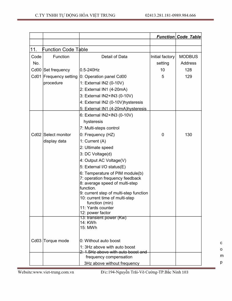
C.TY TNHH TỰ ĐỘNG HÓA VIỆT TRUNG 02413.281.181-0989.984.666
Website:www.viet-trung.com.vn Đ/c:194-Nguyễn Trãi-Võ Cường-TP.Bắc Ninh 103
Function Code Table 11. Function Code Table
Code
No.
Function Detail of Data Initial factory
setting
MODBUS
Address
Cd00 Set frequency 0.5-240Hz 10 128
Cd01 Frequency setting
procedure
Cd02 Select monitor
display data
0: Operation panel Cd00
1: External IN2 (0-10V)
2: External IN1 (4-20mA)
3: External IN2+IN3 (0-10V)
4: External IN2 (0-10V)hysteresis
5: External IN1 (4-20mA)hysteresis
6: External IN2+IN3 (0-10V)
hysteresis
7: Multi-steps control
0: Frequency (HZ)
1: Current (A)
2: Ultimate speed
3: DC Voltage(d)
4: Output AC Voltage(V)
5: External I/O status(E)
6: Temperature of PIM module(b) 7: operation frequency feedback 8: average speed of multi-step function. 9: current step of multi-step function 10: current time of multi-step
function (min) 11: Yards counter 12: power factor 13: transient power (Kw) 14: KWh 15: MWh
5 129
0 130
Cd03 Torque mode 0: Without auto boost
1: 3Hz above with auto boost 2: 1.5Hz above with auto boost and
frequency compensation
3Hz above without frequency
c
o
m
p

C.TY TNHH TỰ ĐỘNG HÓA VIỆT TRUNG 02413.281.181-0989.984.666
Website:www.viet-trung.com.vn Đ/c:194-Nguyễn Trãi-Võ Cường-TP.Bắc Ninh 104
ensation 1 131
Cd04 Operation
command
0: Operation panel
1: External signal
0 132
- 53 -

C.TY TNHH TỰ ĐỘNG HÓA VIỆT TRUNG 02413.281.181-0989.984.666
Website:www.viet-trung.com.vn Đ/c:194-Nguyễn Trãi-Võ Cường-TP.Bắc Ninh 105
Function Code Table
Code
No.
Function Detail of Data Initial factory
setting
MODBUS
Address
Cd05 V/F pattern 1-10 fixed Modes
11: Set by CD57, CD58
12: 1.5 power curve
13: 1.7 power curve
14: square curve
2 133
Cd06 Motor rated
current
25-100% 100 134
Cd07 Torque boost 0-15.0 (0-15.0%) 5 135
Cd08 1st acceleration
time
Cd09 1st deceleration
time
Cd10 2nd acceleration
time
Cd11 2nd deceleration
time
0.1-6000 (S/50HZ) 5 136
0.1-6000 (S/50HZ) 5 137 0.1-6000 (S/50HZ) 10 138
0.1-6000 (S/50HZ) 10 139
Cd12 No.2 frequency HZ 20 140
Cd13 No.3 frequency HZ 30 141
Cd14 No.4 frequency HZ 40 142
Cd15 Jogging frequency 0.5HZ-30HZ 5 143
Cd16 Start frequency 0.5HZ-60HZ 1 144
Cd17 Upper limit
frequency
Cd18 Lower limit
frequency
Cd19 Jogging
acceleration /
deceleration time
10-240HZ 60 145
0-100HZ 0 146
0.1-10 (S/50HZ) 1 147
Cd20 Jump frequency 1 HZ 0 148
Cd21 Jump frequency 2 HZ 0 149
Cd22 Jump frequency width

C.TY TNHH TỰ ĐỘNG HÓA VIỆT TRUNG 02413.281.181-0989.984.666
Website:www.viet-trung.com.vn Đ/c:194-Nguyễn Trãi-Võ Cường-TP.Bắc Ninh 106
0-6HZ 0 150
- 54 -

C.TY TNHH TỰ ĐỘNG HÓA VIỆT TRUNG 02413.281.181-0989.984.666
Website:www.viet-trung.com.vn Đ/c:194-Nguyễn Trãi-Võ Cường-TP.Bắc Ninh 107
Function Code Table
Code
No.
Function Detail of Data Initial factory
setting
MODBUS
Address
Cd23 Braking mode 0: de-active
1: Active when stop
2: Active when start
3: Active both stop and start
0 151
Cd24 DC braking
frequency
Cd25 DC braking
voltage
1-60HZ 1 152 0-15 5 153
Cd26 DC braking time 1-60 Sec. 1 154
Cd27 Operation
direction setting
Cd28 Restart in
instantaneous
power failure /
Free run start
0: Both forward and reverse
1: Forward only
2: Reverse only
0: Without / Without
1: With / Without
2: Without / With
3: With / With
0 155
0 156
Cd29 Time 1-9000 (Sec.) 5 157
Cd30 “Stop” function at
panel key under
the operation of
external sequence
0: Impossible
1: Possible
1 158
Cd31 Initialize data 0: No change 0
1: Data at the time of shipment
Cd36 Memory clear for
fault annunciation
Cd37 Frequency gain
setting
Cd38 Analog output
calibrate
Cd39 Frequency
command bias
1: Memory clear 0
20-200% 100 165 90-110% 100 166
0-250 125 167

C.TY TNHH TỰ ĐỘNG HÓA VIỆT TRUNG 02413.281.181-0989.984.666
Website:www.viet-trung.com.vn Đ/c:194-Nguyễn Trãi-Võ Cường-TP.Bắc Ninh 108
Cd40 No.5 Frequency HZ 45 168
Cd41 No.6 Frequency HZ 50 169
Cd42 No.7 Frequency HZ 55 170
Cd43 No.8 Frequency HZ 60 171
- 55 -

C.TY TNHH TỰ ĐỘNG HÓA VIỆT TRUNG 02413.281.181-0989.984.666
Website:www.viet-trung.com.vn Đ/c:194-Nguyễn Trãi-Võ Cường-TP.Bắc Ninh 109
Function Code Table
Code
No.
Function Detail of Data Initial factory
setting
MODBUS
Address
Cd44 Stop mode 0: Decelerate stop
1: Free run stop
2: Free run stop after
deceleration time is reached
0 172
Cd45 Detect frequency
level
0.5-240HZ 0.5 173
Cd46 Speed multiplier 0.01~500 1 174
Cd47 Relay 1 output
select
Cd48 Relay 2 output
select
0-6 1 175
0-6 1 176
Cd49 Lock data 0: Data change capable
1: Data change not capable
0 177
Cd50 Software version Read only x 178
Cd51 Motor rated
voltage
10-450
200V Series×1
380V Series×1.73
220 179
Cd52 Motor no-load
current
Cd53 Motor slip
differential boost
5-60% 30 180
0.0-10.0% 0 181
Cd54 External analog
output select
0: Display output frequency
1: Display output current
0 182
Cd55 Field select 0~60% 20 183
Cd56 Current stall
preventive
Cd57 Max. frequency
FH setting
10-200% 180 184 10-240HZ (FH) 60 185
Cd58 Motor rated
frequency Fb
10-240HZ (Fb)
FH ≧Fb
60 186

C.TY TNHH TỰ ĐỘNG HÓA VIỆT TRUNG 02413.281.181-0989.984.666
Website:www.viet-trung.com.vn Đ/c:194-Nguyễn Trãi-Võ Cường-TP.Bắc Ninh 110
- 56 -

C.TY TNHH TỰ ĐỘNG HÓA VIỆT TRUNG 02413.281.181-0989.984.666
Website:www.viet-trung.com.vn Đ/c:194-Nguyễn Trãi-Võ Cường-TP.Bắc Ninh 111
Function Code Table
Code
No.
Function Detail of Data Initial factory
setting
MODBUS
Address
Cd59 MBS / RST JOG / 5DF
Set DI4 DI6 DI3 DI5 0 JOG MBS 3DF 2DF
0 187
3DF / DOWN
4DF / UP 1 JOG/
yards RST 3DF/
Down% 2DF/ Up%
2 5DF MBS 3DF 2DF 3 5DF RST 3DF 2DF 4 JOG MBS DOWN UP 5 JOG RST DOWN UP 6 5DF MBS DOWN UP 7 5DF RST DOWN UP
Cd60 V/F Frequency FC 0.5-240HZ 20 188
Cd61 P.W.M.
Frequency
1: 4KHZ
2: 6KHZ
3: 8KHZ
4: 10KHZ
2 189
Cd62 PWM Frequency2 15~40 30 190 Cd63 Switch point for 3rd 5~17 7 191
quarter and 2nd
quarter Cd64 Dynamic braking 0~1 1 192
mode Cd65 Instant initial field 1~7 1 193
time Cd66 Digital filter 1~6 5 194
function Cd67 Power source 0~30 0 195
positioning accuracy calibration
Cd68 Dead Time 0~10 10 196 compensation adjustment
Cd69 Reserved Cd70 Dynamic Braking 120~140% 130 198
active level Cd71 Over Voltage 130~145% 140 199
prevention function active point

C.TY TNHH TỰ ĐỘNG HÓA VIỆT TRUNG 02413.281.181-0989.984.666
Website:www.viet-trung.com.vn Đ/c:194-Nguyễn Trãi-Võ Cường-TP.Bắc Ninh 112
Cd72 Reserved Cd77 Kwh, Mwh 1: clear 0
memory clear
- 57 -

C.TY TNHH TỰ ĐỘNG HÓA VIỆT TRUNG 02413.281.181-0989.984.666
Website:www.viet-trung.com.vn Đ/c:194-Nguyễn Trãi-Võ Cường-TP.Bắc Ninh 113
Function Code Table
Code
No.
Function Detail of Data Initial factory
setting
MODBUS
Address
Cd79 Auto record when 0: de-active 1 power off
Cd80 Modbus protocol data frame and Communications mode setting
1: active 0: De-active 1: Active with RTU mode, only for
monitoring.(8,n,1) 2: Active with RTU mode, change
general parameter.(8,n,1) 3: Active with RTU mode, change of
general parameter. Operational command by remote control.(8,n,1)
4: Active with ASCII mode, only for monitoring.(7,e,1)
5: Active with ASCII mode, change general parameter.(7,e,1)
6: Active with ASCII mode, change of general parameter. Operational
command by remote control.(7,e,1)
3 208
Cd81 RS485 Communication ID Setting
1〜240 1 209
Cd82 RS485 Baud rate 0:2400 bps 1:4800 bps 2:9600 bps 3:19200 bps
Series
2 210
211 Cd83 communication
response time. 0〜15 0
Cd84 Series Communication broadcasting function selection
Cd85 Reserved
0: Active both group and global broadcasting 1: Active only group broadcasting. 2: Active only global broadcasting 3: De-active both group and global
broadcasting.
0 212
Cd86 RS485 interface 0: Use A+, A- port as RS422/RS485 0 selection
Cd87 Reserved
with modbus protocol 1: Use A+, A- port be de-active 2: only use remote key pad
C.TY TNHH TỰ ĐỘNG HÓA VIỆT TRUNG 02413.281.181-0989.984.666
Website:www.viet-trung.com.vn Đ/c:194-Nguyễn Trãi-Võ Cường-TP.Bắc Ninh 114
- 58 -

C.TY TNHH TỰ ĐỘNG HÓA VIỆT TRUNG 02413.281.181-0989.984.666
Website:www.viet-trung.com.vn Đ/c:194-Nguyễn Trãi-Võ Cường-TP.Bắc Ninh 115
Function Code Table
Code
No.
Function Detail of Data Initial factory
setting
MODBUS
Address
CE00 Fault annunciation OCPA OCPN OCPD
(The last) CE01 Fault annunciation OCS OC OL
(Before the last) CE02 Fault annunciation
(The 2nd before OU PLU the last)
nOnE 228
nOnE 229 nOnE 230
CE03 Fault annunciation Erc nonE nOnE 231 (The 3rd before the last)
CE04 Reserved 0 st
CE11 1 step speed
setting 0〜240Hz 0 233
nd
CE12 2 step speed
setting 0〜240Hz 0 234
rd
CE13 3 step speed
setting 0〜240Hz 0 235
th
CE14 4 step speed
setting 0〜240Hz 0 236
th
CE15 5 step speed
setting 0〜240Hz 0 237
th
CE16 6 step speed
setting 0〜240Hz 0 238
th
CE17 7 step speed
setting 0〜240Hz 0 239
th
CE18 8 step speed
setting 0〜240Hz 0 240
th
CE19 9 step speed
setting 0〜240Hz 0 241
th
CE20 10 step speed
setting 0〜240Hz 0 242
st
CE21 1 step time
setting 0〜100Min 0 249
nd
CE22 2 step time
setting 0〜100Min 0 250
rd
CE23 3 step time
setting 0〜100Min 0 251
th
CE24 4 step time
setting 0〜100Min 0 252
th
CE25 5 step time

C.TY TNHH TỰ ĐỘNG HÓA VIỆT TRUNG 02413.281.181-0989.984.666
Website:www.viet-trung.com.vn Đ/c:194-Nguyễn Trãi-Võ Cường-TP.Bắc Ninh 116
setting 0〜100Min 0 253
th
CE26 6 step time
setting 0〜100Min 0 254
- 59 -

C.TY TNHH TỰ ĐỘNG HÓA VIỆT TRUNG 02413.281.181-0989.984.666
Website:www.viet-trung.com.vn Đ/c:194-Nguyễn Trãi-Võ Cường-TP.Bắc Ninh 117
CE47
CE48
CE50
CE55
Function Code Table
Code
No. th
Function Detail of Data Initial factory
setting
MODBUS
Address
CE27 7 step time
setting 0〜100Min 0 255
th
CE28 8 step time
setting 0〜100Min 0 256
th
CE29 9 step time
setting 0〜100Min 0 257
th
CE30 10 step time
setting 0〜100Min 0 258
CE37 1st up Speed % 0~10.0% 0 265 CE38 2nd up Speed % 0~10.0% 0 266 CE39 3rd up Speed % 0~10.0% 0 267 CE40 1st up Speed time 0~200 min 0 268 CE41 2nd up Speed time 0~200 min 0 269 CE42 1st down Speed % 0~10.0% 0 270
nd
CE43 2 down Speed
% 0~10.0% 0 271
CE44 3rd down Speed % 0~10.0% 0 272 st
CE45 1 down Speed
time 0~200 min 0 273
nd
CE46 2 down Speed
time 0~200 min 0 274
Multi-step function
mode selection 0〜3 0 275
Multi-step function
reset 0〜1 0
Multi-step function
CE49 continuous operation selection
0〜2 0 277
Multi-step function
time error adjust 0〜256 100
CE52 File select 1〜6 1
CE53 All Files Restore 0〜1 0
CE54 File copy 1〜6 0
Yards counter
clear 0~1 0
Set Target Feedback 0 De-active 1 CE67 IN1
CE61 PI control Target value/feedback

C.TY TNHH TỰ ĐỘNG HÓA VIỆT TRUNG 02413.281.181-0989.984.666
Website:www.viet-trung.com.vn Đ/c:194-Nguyễn Trãi-Võ Cường-TP.Bắc Ninh 118
terminal select
2 CE67 IN2 3 CE67 IN3 4 IN1 IN2 5 IN1 IN3 6 IN3 IN1 7 IN3 IN2
0 289
- 60 -
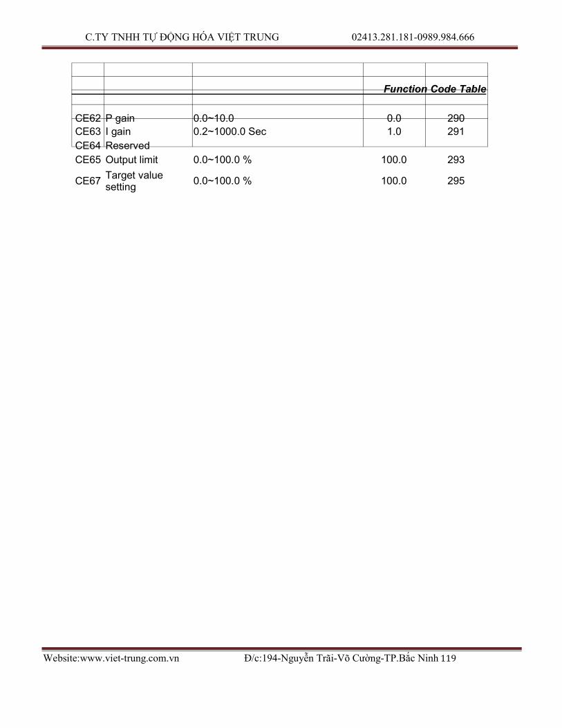
C.TY TNHH TỰ ĐỘNG HÓA VIỆT TRUNG 02413.281.181-0989.984.666
Website:www.viet-trung.com.vn Đ/c:194-Nguyễn Trãi-Võ Cường-TP.Bắc Ninh 119
CE67
Function Code Table
CE62 P gain 0.0~10.0 0.0 290
CE63 I gain 0.2~1000.0 Sec 1.0 291
CE64 Reserved
CE65 Output limit 0.0~100.0 % 100.0 293
Target value
setting 0.0~100.0 % 100.0 295

C.TY TNHH TỰ ĐỘNG HÓA VIỆT TRUNG 02413.281.181-0989.984.666
Website:www.viet-trung.com.vn Đ/c:194-Nguyễn Trãi-Võ Cường-TP.Bắc Ninh 120
- 61 -

C.TY TNHH TỰ ĐỘNG HÓA VIỆT TRUNG 02413.281.181-0989.984.666
Website:www.viet-trung.com.vn Đ/c:194-Nguyễn Trãi-Võ Cường-TP.Bắc Ninh 121
Modbus Address of Display Data 12. Modbus Address of Display Data
Description Notes
Range Unit MODBUS
Address
Operation frequency 0〜24000 0.01HZ 328
Current feedback 0〜9999 0.1A 329
Operation command 0〜24000 0.01HZ 330
DC voltage 0〜9999 0.1V 331
Output voltage Vac=Output voltage / 2 0〜9999 0.1 332
External terminal
mode
0〜255 333
Module Temperature 112〜1130 0.1℃ 234
Operation status Bit2: 0=Stop, 1=RUN
Bit14: 0=FR, 1=RR
Operation command MASTER changes: Bit0: FWD command Bit1: REV command Clear Bit0 Bit1: Stop command
Bit2: Reset after failure
command
335
336
Failure Bit 4,3,2,1,0 =
0:None
4:OCPA
5:OCPd
6:OCPn
8:OV
10:OH
12:OL
14:OC
15:PLU
16:OL2
17:BuOH
337
Power factor 0~100 0.01 338 Instant power 0~65535 0.01KW 339 KW-H 0~9999 0.01KW
H 340
MW-H 0~65535 0.1MWH 341 Current time of
multi-step function 0~999 1min 342
Yards counter’s low 8bits & Current step of multi-step function
0~7 bit: Current step of multi-step function 8~15 bit : Yards counter’s low 8bits
0〜16 1step
0〜255 0.01 yard
343
Yards counter’s high 16bits
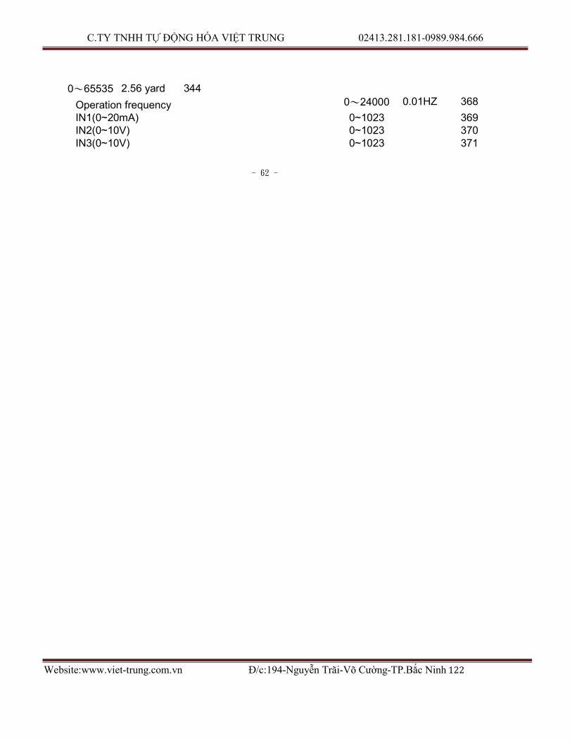
C.TY TNHH TỰ ĐỘNG HÓA VIỆT TRUNG 02413.281.181-0989.984.666
Website:www.viet-trung.com.vn Đ/c:194-Nguyễn Trãi-Võ Cường-TP.Bắc Ninh 122
0〜65535 2.56 yard 344
Operation frequency 0〜24000 0.01HZ 368
IN1(0~20mA) 0~1023 369 IN2(0~10V) 0~1023 370 IN3(0~10V) 0~1023 371
- 62 -

C.TY TNHH TỰ ĐỘNG HÓA VIỆT TRUNG 02413.281.181-0989.984.666
Website:www.viet-trung.com.vn Đ/c:194-Nguyễn Trãi-Võ Cường-TP.Bắc Ninh 123
Serial Communications User Manual 13. Serial Communications User Manual
This product built in with standard RS422/RS485 communicate port, support
international standard MODBUS protocol, user can monitor single or many inverters
by using PLC, PC, industrial computer or other equipment which support MODBUS
protocol
A. The physical link
The wiring of this product can use either RS422(4 wires) or RS485(2wires), by jumper
J11 and J13.
J11 J13 Figure
Single RS422 Pin 2-3 short Open 13-1
Single RS485 Pin 1-2 short Open 13-2
Remote keyboard &
Single RS485
Pin 1-2 short
Pin 2-3 short
Short 13-3
INVERTER INVERTER
………………..
A+ A- B+ B- A+ A- B+ B- 1/2W 150Ω
R
R+
R- Master
T+
T-
R R R 1/2W 150Ω
1/2W 150Ω
Fig 13-1

C.TY TNHH TỰ ĐỘNG HÓA VIỆT TRUNG 02413.281.181-0989.984.666
Website:www.viet-trung.com.vn Đ/c:194-Nguyễn Trãi-Võ Cường-TP.Bắc Ninh 124
- 63 -

C.TY TNHH TỰ ĐỘNG HÓA VIỆT TRUNG 02413.281.181-0989.984.666
Website:www.viet-trung.com.vn Đ/c:194-Nguyễn Trãi-Võ Cường-TP.Bắc Ninh 125
Serial Communications User Manual
INVERTER INVERTER
………………..
A+ A- B+ B- A+ A- B+ B- 1/2W 150Ω
R
Data+
Data-
Master
R 1/2W 150Ω
Fig13-2
INVERTER For remote keyboard
……...
INVERTER
RJ45
REMOTE
A+ A- B+ B-
RJ45
REMOTE A+ A- B+ B-
Master
Data+
Data-
R
1/2W 150Ω
R 1/2W 150Ω
Fig13-3 Note:
a. When use REMOTE Keyboard and second set RS485 at the same time,please
notice that external terminal Vout will be disabled.
b. When use RS422 (4wires), The ‘REMOTE’ socket cannot connect to any device.
C.TY TNHH TỰ ĐỘNG HÓA VIỆT TRUNG 02413.281.181-0989.984.666
Website:www.viet-trung.com.vn Đ/c:194-Nguyễn Trãi-Võ Cường-TP.Bắc Ninh 126
c. Single transaction can read up to 10 continuous data from slave device.
d. It can connect up to 32 devices in single net.
e. The R in wiring diagram is terminal resister, only used on the device in the end of
communication line.
- 64 -
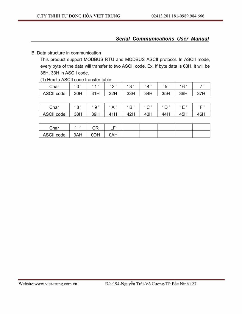
C.TY TNHH TỰ ĐỘNG HÓA VIỆT TRUNG 02413.281.181-0989.984.666
Website:www.viet-trung.com.vn Đ/c:194-Nguyễn Trãi-Võ Cường-TP.Bắc Ninh 127
Serial Communications User Manual
B. Data structure in communication
This product support MODBUS RTU and MODBUS ASCII protocol. In ASCII mode,
every byte of the data will transfer to two ASCII code. Ex. If byte data is 63H, it will be
36H, 33H in ASCII code.
(1) Hex to ASCII code transfer table
Char ‘ 0 ’ ‘ 1 ’ ‘ 2 ’ ‘ 3 ’ ‘ 4 ’ ‘ 5 ’ ‘ 6 ’ ‘ 7 ’
ASCII code 30H 31H 32H 33H 34H 35H 36H 37H
Char ‘ 8 ’ ‘ 9 ’ ‘ A ’ ‘ B ’ ‘ C ’ ‘ D ’ ‘ E ’ ‘ F ’
ASCII code 38H 39H 41H 42H 43H 44H 45H 46H
Char ‘ : ‘ CR LF
ASCII code 3AH 0DH 0AH

C.TY TNHH TỰ ĐỘNG HÓA VIỆT TRUNG 02413.281.181-0989.984.666
Website:www.viet-trung.com.vn Đ/c:194-Nguyễn Trãi-Võ Cường-TP.Bắc Ninh 128
- 65 -

C.TY TNHH TỰ ĐỘNG HÓA VIỆT TRUNG 02413.281.181-0989.984.666
Website:www.viet-trung.com.vn Đ/c:194-Nguyễn Trãi-Võ Cường-TP.Bắc Ninh 129
Serial Communications User Manual C. Function code
This product support Function code 03H and 06H in MODBUS protocol. (1) Function 03H:Read holding register
Read the binary contents of holding registers (4 x references) in the slave. Broadcast is not supported. The maximum parameters supported by various controller models are listed on page.
Ex: Read data from 3 continuous addresses in register. The beginning address is
0080H, the data frame are listed as follow. Query
Field Name Example (hex) ASCII code RTU 8-Bit Field Header ‘ : ’ (colon) None Slave Address F0 F 0 1111 0110 Function 03 0 3 0000 0011 Start Address Hi 00 0 0 0000 0000 Start Address Lo 80 8 0 1000 0000 No. of Register Hi 00 0 0 0000 0000 No. of Register Lo 03 0 3 0000 0011 Error Check LRC (2 chars) CRC (16 bits) Trailer CR LF None Total Bytes 17 8
Response
Field Name Example (hex) ASCII code RTU 8-Bit Field Header ‘ : ’ (colon) None Slave Address F0 F 0 1111 0000 Function 03 0 3 0000 0011 Byte Count 06 0 6 0000 0110 1st Data Hi 03 0 3 0000 0011 1st Data Lo E8 E 8 1110 1000 2nd Data Hi 00 0 0 0000 0000 2nd Data Lo 07 0 7 0000 0111 3rd Data Hi 00 0 0 0000 0000 3rd Data Lo 00 0 0 0000 0000 Error Check LRC (2 chars) CRC (16 bits) Trailer CR LF None Total Bytes 23 11

C.TY TNHH TỰ ĐỘNG HÓA VIỆT TRUNG 02413.281.181-0989.984.666
Website:www.viet-trung.com.vn Đ/c:194-Nguyễn Trãi-Võ Cường-TP.Bắc Ninh 130
- 66 -

C.TY TNHH TỰ ĐỘNG HÓA VIỆT TRUNG 02413.281.181-0989.984.666
Website:www.viet-trung.com.vn Đ/c:194-Nguyễn Trãi-Võ Cường-TP.Bắc Ninh 131
Serial Communications User Manual
(2) Function 06H: preset signal register
Presets a value into a single holding register (4 x reference). When broadcast, the function presets the same register reference in all attached slaves. The maximum parameters supported by various controller models are listed on page.
Ex. To inverter in F0H address protocol, pre set data 6000(1770H) into 0080H register,
the protocol frame will listed as below.
Query Field Name Example (hex) ASCII code RTU 8-Bit Field Header ‘ : ’ (colon) None Slave Address F0 F 0 1111 0110 Function 06 0 6 0000 0110 Register Address Hi 00 0 0 0000 0000 Register Address Lo 80 8 0 1000 0000 Preset Data Hi 17 1 7 0001 0111 Preset Data Lo 70 7 0 0777 0000 Error Check LRC (2 chars) CRC (16 bits) Trailer CR LF None Total Bytes 17 8
Response Field Name Example (hex) ASCII code RTU 8-Bit Field Header ‘ : ’ (colon) None Slave Address F0 F 0 1111 0110 Function 06 0 6 0000 0110 Register Address Hi 00 0 0 0000 0000 Register Address Lo 80 8 0 1000 0000 Preset Data Hi 17 1 7 0001 0111 Preset Data Lo 70 7 0 0777 0000 Error Check LRC (2 chars) CRC (16 bits) Trailer CR LF None Total Bytes 17 8
D. Error check Generation
(1) LRC Generation Add all bytes in the message, excluding the starting colon and ending CRLF. Add them into an eight-bit field, so that carries will be discarded. Subtract the final field value from FF hex (all 1's), to produce the ones complement. Add 1 to produce the two's-complement. Ex. The query data is F0H + 06H + 00H + 80H + 17H + 70H = FDH, the two’s complement is 03H. The ‘0’ & ‘3’ will be the
C.TY TNHH TỰ ĐỘNG HÓA VIỆT TRUNG 02413.281.181-0989.984.666
Website:www.viet-trung.com.vn Đ/c:194-Nguyễn Trãi-Võ Cường-TP.Bắc Ninh 132
LRC.
- 67 -

C.TY TNHH TỰ ĐỘNG HÓA VIỆT TRUNG 02413.281.181-0989.984.666
Website:www.viet-trung.com.vn Đ/c:194-Nguyễn Trãi-Võ Cường-TP.Bắc Ninh 133
Serial Communications User Manual
(2) CRC Generation
Generating a CRC
Step 1 Load a 16-bit register with FFFF hex (all 1's). Call this the CRC register.
Step 2 Exclusive OR the first eight-bit byte of the message with the low order byte of the 16-bit CRC register, putting the result in the CRC register.
Step 3 Shift the CRC register one bit to the right (toward the LSB), zero filling the MSB. Extract and examine the LSB.
Step 4 If the LSB is 0, repeat Step 3 (another shift). If the LSB is 1, Exclusive OR the CRC register with the polynomial value A001 hex (1010 0000 0000 0001).
Step 5 Repeat Steps 3 and 4 until eight shifts have been performed. When this is done, a complete eight-bit byte will have been processed.
Step 6 Repeat Steps 2 ... 5 for the next eight-bit byte of the message. Continue doing this until all bytes have been processed. The final contents of the CRC register is the CRC value.
Step 7 When the CRC is placed into the message, its upper and lower bytes must be swapped as described below.
Pseudo code for generating a CRC-16:
CONST ARRAY BUFFER /* data, ex: F0h, 06h, 00h, 80h, 17h, 70h */
CONST WORD POLYNOMIAL = 0A001h /* X16 = X15 + X2 + X1 */
/* SUBROTINUE OF CRC CACULATE START */
CRC_CAL(LENGTH)
VAR INTEGER LENGTH;
{ VAR WORD CRC16 = 0FFFFH; /* CRC16 initial */
VAR INTEGER = i,j; /* LOOP COUNTER */
VAR BYTE DATA; /* DATA BUFFER */
FOR (i=1;i=LENGTH;i++) /* BYTE LOOP */
{ DATA == BUFFER[i];
CRC16 == CRC16 XOR DATA
FOR (j=1;j=8;J++) /* BIT LOOP */
{ IF (CRC16 AND 0001H) = 1 THEN
CRC16 == (CRC16 SHR 1) XOR POLYNOMIAL;
ELSE
CRC16 == CRC16 SHR 1;
DATA == DATA SHR 1;
};
C.TY TNHH TỰ ĐỘNG HÓA VIỆT TRUNG 02413.281.181-0989.984.666
Website:www.viet-trung.com.vn Đ/c:194-Nguyễn Trãi-Võ Cường-TP.Bắc Ninh 134
};
RETURN(CRC16);
};
- 68 -

C.TY TNHH TỰ ĐỘNG HÓA VIỆT TRUNG 02413.281.181-0989.984.666
Website:www.viet-trung.com.vn Đ/c:194-Nguyễn Trãi-Võ Cường-TP.Bắc Ninh 135
Serial Communications User Manual
E. Group and Global Broadcast function.
(1) Group Broadcast
User can use this function to control certain group of inverter at the same time.
When master send out group address data, the slave inverters will react when receive
order, but will not send any signal back to master.
(2) Global Broadcast
User can use this function to control all inverters at the same time. When master
global broadcast, all slaves inverters will react after receive order, but will not send any
signal back to master.
Group and Global broadcast address should be recognized refer to table as
below, when the group and global broadcast address is in use.
There are 240 addresses in total for inverter setting, which means it can
connect up to 240 inverters at the same time, and provide 1 Global Broadcast
address 15-group address. Each group address can control up to 16 inverters, and
user can set it.
Group Individual
Address
Group address Global address
Group1 1…16 241 0
Group 2 17…32 242 0
Group 3 33…48 243 0
Group 4 49...64 244 0
Group 5 65...80 245 0
Group 6 81…96 246 0
Group 7 97…112 247 0
Group 8 113...128 248 0
Group 9 129...144 249 0
Group 10 145...160 250 0
Group 11 161...176 251 0
Group 12 177...192 252 0
Group 13 193...208 253 0
Group 14 209...224 254 0
Group 15 225...240 255 0

C.TY TNHH TỰ ĐỘNG HÓA VIỆT TRUNG 02413.281.181-0989.984.666
Website:www.viet-trung.com.vn Đ/c:194-Nguyễn Trãi-Võ Cường-TP.Bắc Ninh 136
- 69 -