Embed Size (px)
Citation preview

Spirent Communications | <Product Name> Data Sheet 1
Datasheet MS3063 Issue 3-40 June 20152015
GSS6300 Multi-GNSS Generator Datasheet With Product Specification

Spirent Communications | GSS6300 Multi-GNSS Generator Datasheet
Datasheet MS3063 Issue 3-40 June 2015
PROPRIETARY INFORMATIONTHE INFORMATION CONTAINED IN THIS DOCUMENT IS THE PROPERTY OF SPIRENT COMMUNICATIONS PLC. EXCEPT AS SPECIFICALLY AUTHORISED IN WRITING BY SPIRENT COMMUNICATIONS PLC, THE HOLDER OF THIS DOCUMENT SHALL KEEP ALL INFORMATION CONTAINED HEREIN CONFIDENTIAL AND SHALL PROTECT SAME IN WHOLE OR IN PART FROM DISCLOSURE AND DISSEMINATION TO ALL THIRD PARTIES TO THE SAME DEGREE IT PROTECTS ITS OWN CONFIDENTIAL INFORMATION. © COPYRIGHT SPIRENT COMMUNICATIONS PLC 2009 - 2015. The ownership of all other registered trademarks used in this document is duly acknowledged

Spirent Communications | GSS6300 Multi-GNSS Generator Datasheet
Datasheet MS3063 Issue 3-40 June 2015 3
Table of Contents
Purpose of this document .............................................................................................................................................. 5
About the GSS6300 Multi-GNSS Generator .................................................................................................................. 6
Key features ................................................................................................................................................................... 6
What the GSS6300 Multi-GNSS Generator does ........................................................................................................ 7
How the GSS6300 Multi-GNSS Generator works ....................................................................................................... 7
GSS6100 and GSS4100 Compatibility ........................................................................................................................... 7
Hardware Description ...................................................................................................................................................... 8
Performance .................................................................................................................................................................. 9
Software and Control .................................................................................................................................................. 15
Environmental and Physical ...................................................................................................................................... 17
Deliverables .................................................................................................................................................................... 19
Applicable Documents .................................................................................................................................................. 19
Appendix A. GPIB Commands ................................................................................................................................. 20
Appendix B. Product Description Codes ................................................................................................................ 21
List of Tables
Table 1 Signal Characteristics ........................................................................................................................................... 9 Table 2 Coaxial Connections ........................................................................................................................................... 11 Table 3 Digital Connectivity (D-Type) .............................................................................................................................. 11 Table 4 GPS / SBAS D-type output settings ................................................................................................................... 12 Table 5 GLONASS D-type output settings ...................................................................................................................... 12 Table 6 Galileo E1b D-type output settings ..................................................................................................................... 12 Table 7 Galileo E1c D-type output settings ..................................................................................................................... 12 Table 8 BeiDou-2 GEO D-type output settings ................................................................................................................ 13 Table 9 BeiDou-2 MEO D-type output settings ............................................................................................................... 13 Table 10 Other Connections ............................................................................................................................................ 13 Table 10 Physical and Electrical ...................................................................................................................................... 17 Table 11 Deliverable Items .............................................................................................................................................. 19 Table 12 Applicable Documents ...................................................................................................................................... 19 Table 13 Common GPIB Commands .............................................................................................................................. 20 Table 14 Product Description Codes ............................................................................................................................... 21
List of Figures
Figure 1 GSS6300 Multi-GNSS Generator ........................................................................................................................ 8 Figure 2 GSS6300 Multi-GNSS Generator Rear Panel (typical) ..................................................................................... 14 Figure 3 Typical SimCHAN screenshot ........................................................................................................................... 15 Figure 4 Typical Front and Rear Panel ............................................................................................................................ 17
Spirent Communications | GSS6300 Multi-GNSS Generator Datasheet
Datasheet MS3063 Issue 3-40 June 2015

Spirent Communications | GSS6300 Multi-GNSS Generator Datasheet
Datasheet MS3063 Issue 3-40 June 2015 5
Purpose of this document This datasheet describes the GSS6300 Multi-GNSS single channel Generator and its functionality.
This datasheet also provides technical data and configuration information. Please speak to your Spirent sales representative before ordering.

Spirent Communications | GSS6300 Multi-GNSS Generator Datasheet
Datasheet MS3063 Issue 3-40 June 2015
About the GSS6300 Multi-GNSS Generator The GSS6300 Multi-GNSS Generator is designed specifically for production test applications. Features such as the GPIB interface for ATE integration, rack mount chassis and in-rack annual calibration are provided as standard and facilitate use of the GSS6300 in the volume manufacturing test environment.
The GSS6300 Multi-GNSS Generator is recommended for manufacturing test applications where a single channel is required for controlled GNSS testing. The GSS6300 enables testing to ensure correct assembly procedure and verification of expected performance parameters, including:
- C / No Calibration
- Doppler Estimation
- Sensitivity Testing
- GNSS Isolation
- Go / No Go Product Testing
Key features Multi-GNSS Support:
- **NEW** All signals can be simulated from one chassis
- **NEW** GPS L1 C/A, SBAS, QZSS L1 C/A Code1
- GLONASS L1 C/A Code
- Galileo CBOC E1 B/C
- BeiDou BD-2 B1
Exceptional performance single channel signal generator
- Hardware designed for low power GNSS signals
- Stable ovenised reference oscillator
- High Doppler Range
- Wide Power Level Range
- Fine Power Level Control
- GPIB (IEEE488), USB, or RS232 control interface
Easy to Use
- User control over test parameters
- Field upgradable
- Straightforward in-rack calibration procedure
- Generates full navigation data
- No requirement to download latest satellite data from external sources
Fully compatible with the industry Standard GSS6100
1 User can run GPS and SBAS simultaneously or, if QZSS ordered with GPS, will also have option to run GPS and QZSS simultaneously
Spirent Communications | GSS6300 Multi-GNSS Generator Datasheet
Datasheet MS3063 Issue 3-40 June 2015 7
What the GSS6300 Multi-GNSS Generator does The GSS6300 Multi-GNSS Generator provides a simulated signal from a GPS, SBAS, GLONASS, Galileo or BeiDou BD2 satellite at the L1 / E1 / B1 frequency.
Generation of signals from the various constellations is enabled by licence keys. If five licence keys are present the GSS6300 Multi-GNSS Generator can generate all the following in a single unit:
[1x GPS signal with 1x SBAS signal] OR [1x GPS signal with 1x QZSS signal]
[1x GLONASS signal]
[1x Galileo signal]
[1x Beidou signal]
The GPS signal will come allocated with SBAS without the need for an additional licence, however, a license will be required if QZSS is needed with the selection being made prior to the start of simulation.
The GSS6300 Multi-GNSS Generator is also supplied with SimCHAN for Windows® software to allow it to be used as a general-purpose laboratory signal generator.
How the GSS6300 Multi-GNSS Generator works The GSS6300 Multi-GNSS Generator includes two principal modes of operation – the primary mode and an alternative mode.
1. In the primary mode, GNSS message generation is controlled via its integral GPIB (IEEE-488) interface, with USB and RS232 also being supported.
2. In the alternative mode, the GSS6300 generates a pre-defined GNSS signal constantly whenever the unit is powered up. The alternative mode may be used when a continuous GNSS source is required for testing. The user may define appropriate satellite code, power level and other parameters to be broadcast during alternative mode operation.
Also supplied with the simulator is a software application package SimCHAN for Windows® which allows the user to control the signal generator as an instrument via its intuitive graphical point-and-click interface, when installed on a suitable PC equipped with USB.
GSS6100 and GSS4100 Compatibility The GSS6300 retains full functional compatibility with the earlier Spirent GSS6100 and GSS4100 products.
With the GSS6300 it is additionally possible to produce not only GPS and SBAS L1 signals but also (with appropriate licence keys) GLONASS, Galileo, BeiDou or QZSS signals if required.
Performance of a GPS enabled GSS6300 has been verified to be equivalent to a GSS6100.
The GSS6300 provides the same modes of operation as the GSS6100 and shares the same remote command instruction set.
If you have any questions about the GSS6300 compatibility with earlier Spirent products, please contact Spirent.
Spirent Communications | GSS6300 Multi-GNSS Generator Datasheet
Datasheet MS3063 Issue 3-40 June 2015
Hardware Description
General
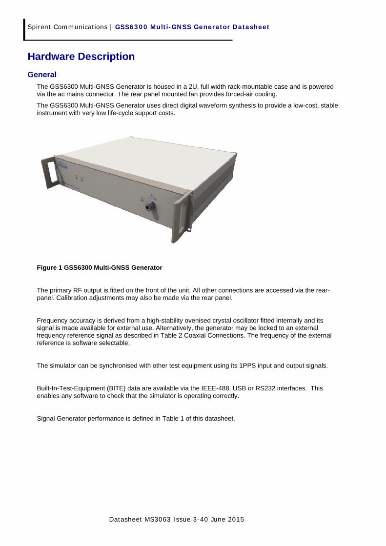
The GSS6300 Multi-GNSS Generator is housed in a 2U, full width rack-mountable case and is powered via the ac mains connector. The rear panel mounted fan provides forced-air cooling.
The GSS6300 Multi-GNSS Generator uses direct digital waveform synthesis to provide a low-cost, stable instrument with very low life-cycle support costs.
Figure 1 GSS6300 Multi-GNSS Generator
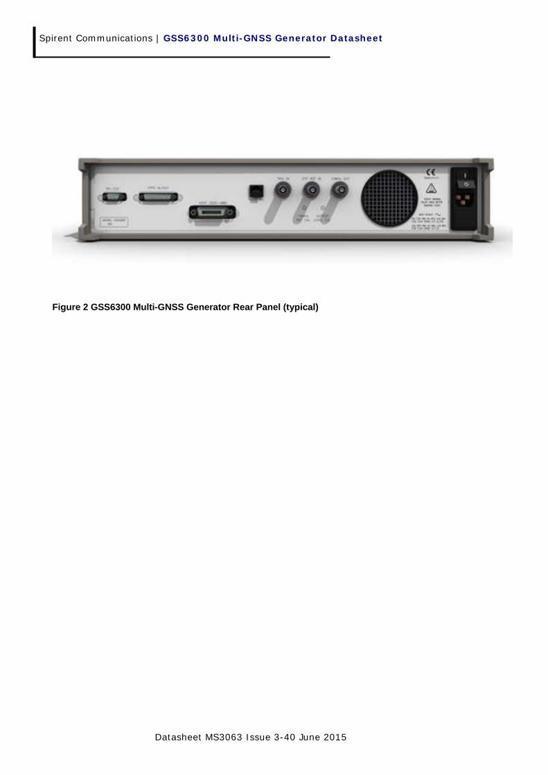
The primary RF output is fitted on the front of the unit. All other connections are accessed via the rear-panel. Calibration adjustments may also be made via the rear panel.
Frequency accuracy is derived from a high-stability ovenised crystal oscillator fitted internally and its signal is made available for external use. Alternatively, the generator may be locked to an external frequency reference signal as described in Table 2 Coaxial Connections. The frequency of the external reference is software selectable.
The simulator can be synchronised with other test equipment using its 1PPS input and output signals.
Built-In-Test-Equipment (BITE) data are available via the IEEE-488, USB or RS232 interfaces. This enables any software to check that the simulator is operating correctly.
Signal Generator performance is defined in Table 1 of this datasheet.

Spirent Communications | GSS6300 Multi-GNSS Generator Datasheet
Datasheet MS3063 Issue 3-40 June 2015 9
Performance Table 1 Signal Characteristics
Parameter Comments Value Units
Signal Sources
GPS L1 and (SBAS or QZSS)
Galileo L1
BeiDou BD2 B1
GLONASS L1
1 and 1
1
1
1
Channel
Channel
Channel
Channel
Signal Codes
GPS L1 C/A
SBAS L1 C/A
Galileo E1 CBOC
GLONASS L1 C/A
BeiDou BD2 B1
QZSS L1 C/A
1 – 63
120 -138
1 – 50
-7 to +6
1 – 37
193 – 202
PRN
PRN
PRN
Channels
PRN
PRN
Signal Dynamics Maximum Relative Velocity 15,000 m/s
Velocity resolution 0.01 m/s
Maximum Relative Acceleration
Maximum Relative Jerk
(for velocity profiles)
100
100
m/s2
m/s3
Signal Bandwidths
GPS L1, Galileo L1 and QZSS L1
Beidou B1
GLONASS L1
20
16
10
MHz
MHz
MHz
In-band2 spectral Purity Note3,
< -30 dBc
Harmonics < -40 dBc
Out-of-band Spectral Purity
(within Bands specified)
GNSS 1500 to 1700 MHz < -954 dBm
Phase Noise close to
Carrier Integrated phase noise, 10Hz to 10kHz offset from carrier
< 0.1 Rad RMS
Time Synchronisation between GNSS signals
Adjustable (using pseudorange)
Resolution
± 1
1
ms
ns
1PPS OUT to RF Delay Timing Uncertainty 1PPS OUT to corresponding event on the RF
0 ± 5 nsecs
Master clock stability
(internal)
Over one day
(24 hours warm up) < 1x10⁻⁹
Nominal signal power at Primary RF port
GPS L1 SBAS L1 GLONASS L1 Galileo E15 BeiDou B1I QZSS L1
-130 -130 -131
-127.0 -133.0 -130
dBm dBm dBm dBm dBm dBm
2 ‘in band’ refers to appropriate constellation signal bandwidth. 3 Referred to unmodulated carrier power at RF output. At nominal RF output power and above. 4 Refer to Appendix B for details 5 Power specified with B and C codes present
Spirent Communications | GSS6300 Multi-GNSS Generator Datasheet
Datasheet MS3063 Issue 3-40 June 2015
Parameter Comments Value Units
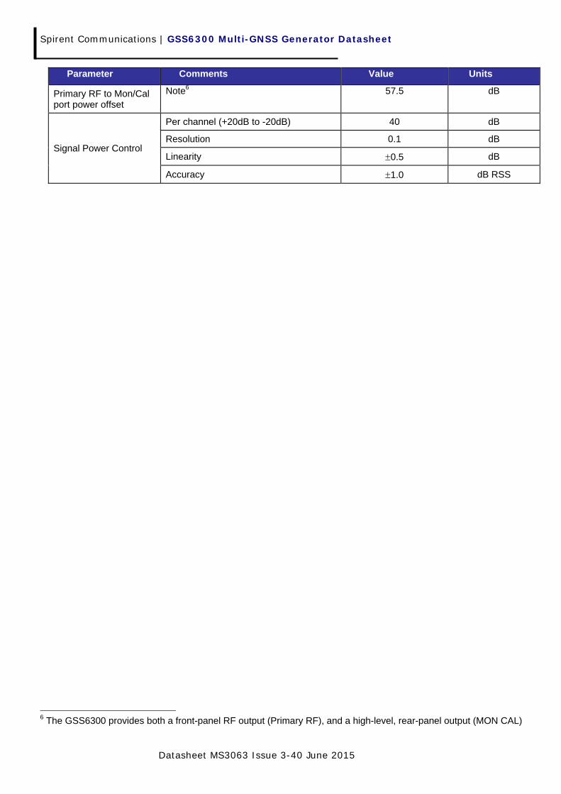
Primary RF to Mon/Cal port power offset
Note6 57.5 dB
Signal Power Control
Per channel (+20dB to -20dB) 40 dB
Resolution 0.1 dB
Linearity 0.5 dB
Accuracy 1.0 dB RSS
6 The GSS6300 provides both a front-panel RF output (Primary RF), and a high-level, rear-panel output (MON CAL)
Spirent Communications | GSS6300 Multi-GNSS Generator Datasheet
Datasheet MS3063 Issue 3-40 June 2015 11
Connectivity
See Environmental and Physical section for connector identification and location.
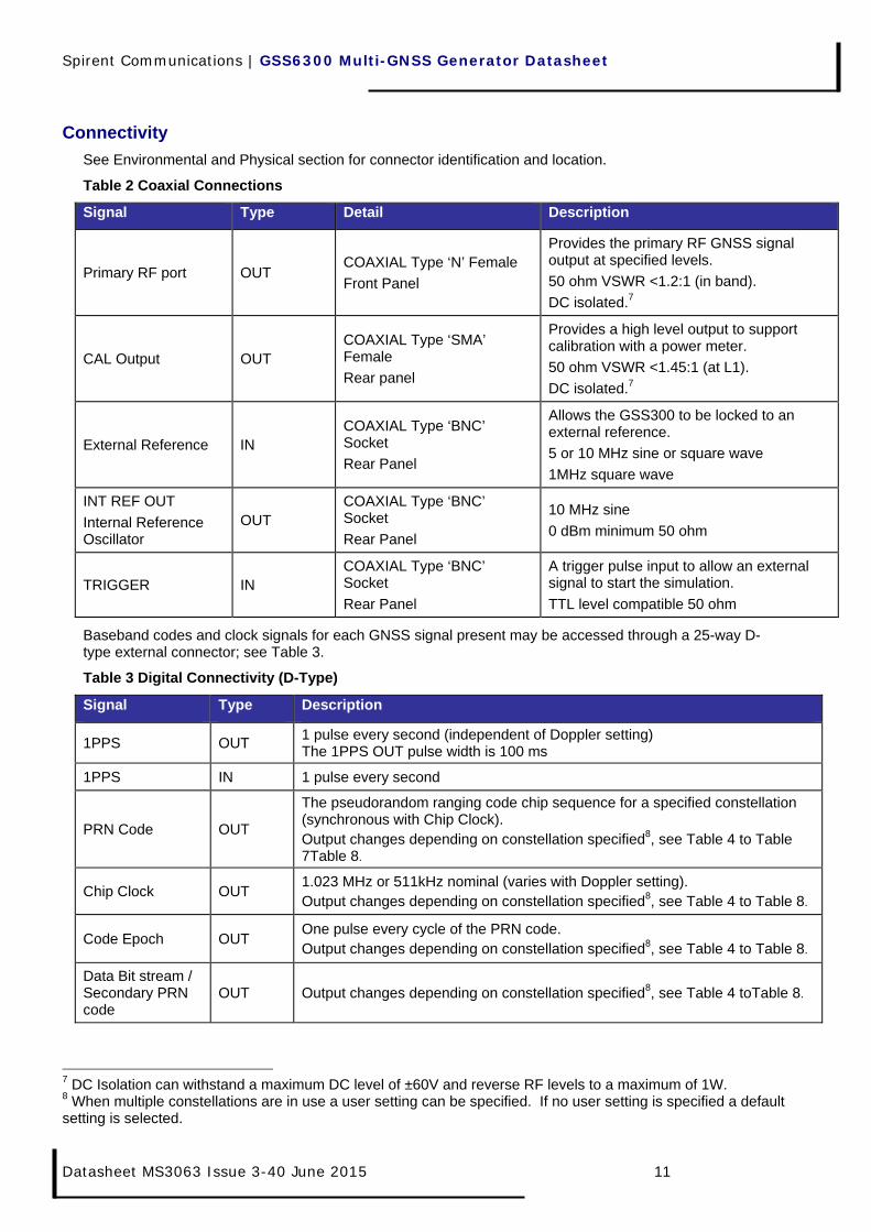
Table 2 Coaxial Connections
Signal Type Detail Description
Primary RF port OUT COAXIAL Type ‘N’ Female
Front Panel
Provides the primary RF GNSS signal output at specified levels.
50 ohm VSWR <1.2:1 (in band).
DC isolated.7
CAL Output OUT COAXIAL Type ‘SMA’ Female
Rear panel
Provides a high level output to support calibration with a power meter.
50 ohm VSWR <1.45:1 (at L1).
DC isolated.7
External Reference IN COAXIAL Type ‘BNC’ Socket
Rear Panel
Allows the GSS300 to be locked to an external reference.
5 or 10 MHz sine or square wave
1MHz square wave
INT REF OUT
Internal Reference Oscillator
OUT COAXIAL Type ‘BNC’ Socket
Rear Panel
10 MHz sine
0 dBm minimum 50 ohm
TRIGGER IN COAXIAL Type ‘BNC’ Socket
Rear Panel
A trigger pulse input to allow an external signal to start the simulation.
TTL level compatible 50 ohm
Baseband codes and clock signals for each GNSS signal present may be accessed through a 25-way D-type external connector; see Table 3.
Table 3 Digital Connectivity (D-Type)
Signal Type Description
1PPS OUT 1 pulse every second (independent of Doppler setting) The 1PPS OUT pulse width is 100 ms
1PPS IN 1 pulse every second
PRN Code OUT
The pseudorandom ranging code chip sequence for a specified constellation (synchronous with Chip Clock). Output changes depending on constellation specified8, see Table 4 to Table 7Table 8.
Chip Clock OUT 1.023 MHz or 511kHz nominal (varies with Doppler setting). Output changes depending on constellation specified8, see Table 4 to Table 8.
Code Epoch OUT One pulse every cycle of the PRN code. Output changes depending on constellation specified8, see Table 4 to Table 8.
Data Bit stream / Secondary PRN code
OUT Output changes depending on constellation specified8, see Table 4 toTable 8.
7 DC Isolation can withstand a maximum DC level of ±60V and reverse RF levels to a maximum of 1W. 8 When multiple constellations are in use a user setting can be specified. If no user setting is specified a default setting is selected.
Spirent Communications | GSS6300 Multi-GNSS Generator Datasheet
Datasheet MS3063 Issue 3-40 June 2015
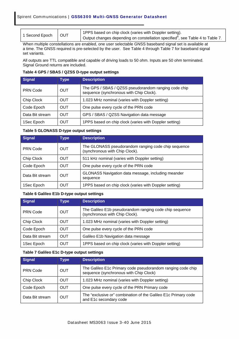
1 Second Epoch OUT 1PPS based on chip clock (varies with Doppler setting). Output changes depending on constellation specified8, see Table 4 to Table 7.
When multiple constellations are enabled, one user selectable GNSS baseband signal set is available at a time. The GNSS required is pre-selected by the user. See Table 4 through Table 7 for baseband signal set variants.
All outputs are TTL compatible and capable of driving loads to 50 ohm. Inputs are 50 ohm terminated. Signal Ground returns are included.
Table 4 GPS / SBAS / QZSS D-type output settings
Signal Type Description
PRN Code OUT The GPS / SBAS / QZSS pseudorandom ranging code chip sequence (synchronous with Chip Clock).
Chip Clock OUT 1.023 MHz nominal (varies with Doppler setting)
Code Epoch OUT One pulse every cycle of the PRN code
Data Bit stream OUT GPS / SBAS / QZSS Navigation data message
1Sec Epoch OUT 1PPS based on chip clock (varies with Doppler setting)
Table 5 GLONASS D-type output settings
Signal Type Description
PRN Code OUT The GLONASS pseudorandom ranging code chip sequence (synchronous with Chip Clock).
Chip Clock OUT 511 kHz nominal (varies with Doppler setting)
Code Epoch OUT One pulse every cycle of the PRN code
Data Bit stream OUT GLONASS Navigation data message, including meander sequence
1Sec Epoch OUT 1PPS based on chip clock (varies with Doppler setting)
Table 6 Galileo E1b D-type output settings
Signal Type Description
PRN Code OUT The Galileo E1b pseudorandom ranging code chip sequence (synchronous with Chip Clock).
Chip Clock OUT 1.023 MHz nominal (varies with Doppler setting)
Code Epoch OUT One pulse every cycle of the PRN code
Data Bit stream OUT Galileo E1b Navigation data message
1Sec Epoch OUT 1PPS based on chip clock (varies with Doppler setting)
Table 7 Galileo E1c D-type output settings
Signal Type Description
PRN Code OUT The Galileo E1c Primary code pseudorandom ranging code chip sequence (synchronous with Chip Clock)
Chip Clock OUT 1.023 MHz nominal (varies with Doppler setting)
Code Epoch OUT One pulse every cycle of the PRN Primary code
Data Bit stream OUT The “exclusive or” combination of the Galileo E1c Primary code and E1c secondary code

Spirent Communications | GSS6300 Multi-GNSS Generator Datasheet
Datasheet MS3063 Issue 3-40 June 2015 13
1Sec Epoch OUT 1PPS based on chip clock (varies with Doppler setting)
Table 8 BeiDou-2 GEO D-type output settings
Signal Type Description
PRN Code OUT
The BeiDou-2 primary pseudorandom ranging code chip sequence (synchronous with Chip Clock)
Chip Clock OUT 2.046 MHz nominal (varies with Doppler setting)
Code Epoch OUT One pulse every cycle of the PRN code
Data Bit stream OUT BeiDou-2 500Hz Navigation data message
1 Second Epoch OUT 1PPS based on chip clock (varies with Doppler setting)
Table 9 BeiDou-2 MEO D-type output settings
Signal Type Description
PRN Code OUT
The BeiDou-2 primary or secondary pseudorandom ranging code chip sequence (synchronous with Chip Clock)
Chip Clock OUT 2.046 MHz nominal (varies with Doppler setting)
Code Epoch OUT One pulse every cycle of the PRN code
Data Bit stream OUT BeiDou-2 50Hz Navigation data message
1 Second Epoch OUT 1PPS based on chip clock (varies with Doppler setting)
Table 10 Other Connections
Connector Type Description
HOST IEEE Comm
Primary Control Interface IEEE-488
For variable length commands, the maximum command length is 2048 characters, which includes the line terminating NULL character (decimal value: 0)
USB Comm Alternative Control Interface using USB 2.0
Not suitable for ATE applications
RS232 Comm
Alternative Control Interface using RS232 serial standard
RS232 port on the GSS6300 is a 9 pin female D-type connector.
The maximum length of any command string is 128 characters, which includes the line terminating NULL character (decimal value: 0)
Spirent Communications | GSS6300 Multi-GNSS Generator Datasheet
Datasheet MS3063 Issue 3-40 June 2015
Figure 2 GSS6300 Multi-GNSS Generator Rear Panel (typical)

Spirent Communications | GSS6300 Multi-GNSS Generator Datasheet
Datasheet MS3063 Issue 3-40 June 2015 15
Software and Control
SimCHAN Software
The GSS6300 Multi-GNSS Generator is supplied with a Microsoft Windows® compatible software package called SimCHAN.
GSS6300 generates a data message based upon a message template stored in non-volatile memory. Any time related fields in the message are automatically inserted based on the start time specified. SimCHAN allows you to redefine the template and transfer it to the GSS6300 via USB.
SimCHAN has a graphical user interface (GUI) which is designed to be simple to use. All parameters are entered in engineering units and operator-entered parameters are checked to be within range. The mode of operation is readily visible on a Toolbar control.
Figure 3 Typical SimCHAN screenshot
The application window allows all parameters to be entered and reviewed. Data entry is easily accomplished using either point and click techniques or keyboard shortcut keys. The form may be saved and re-loaded allowing a user to build sets of standard test cases and quickly switch between them.

Spirent Communications | GSS6300 Multi-GNSS Generator Datasheet
Datasheet MS3063 Issue 3-40 June 2015
Primary Operating Mode
The GSS6300 Multi-GNSS Generator is designed for ATE applications and has been equipped with GPIB, USB and RS232 interfaces for device control when in its Primary operating mode.
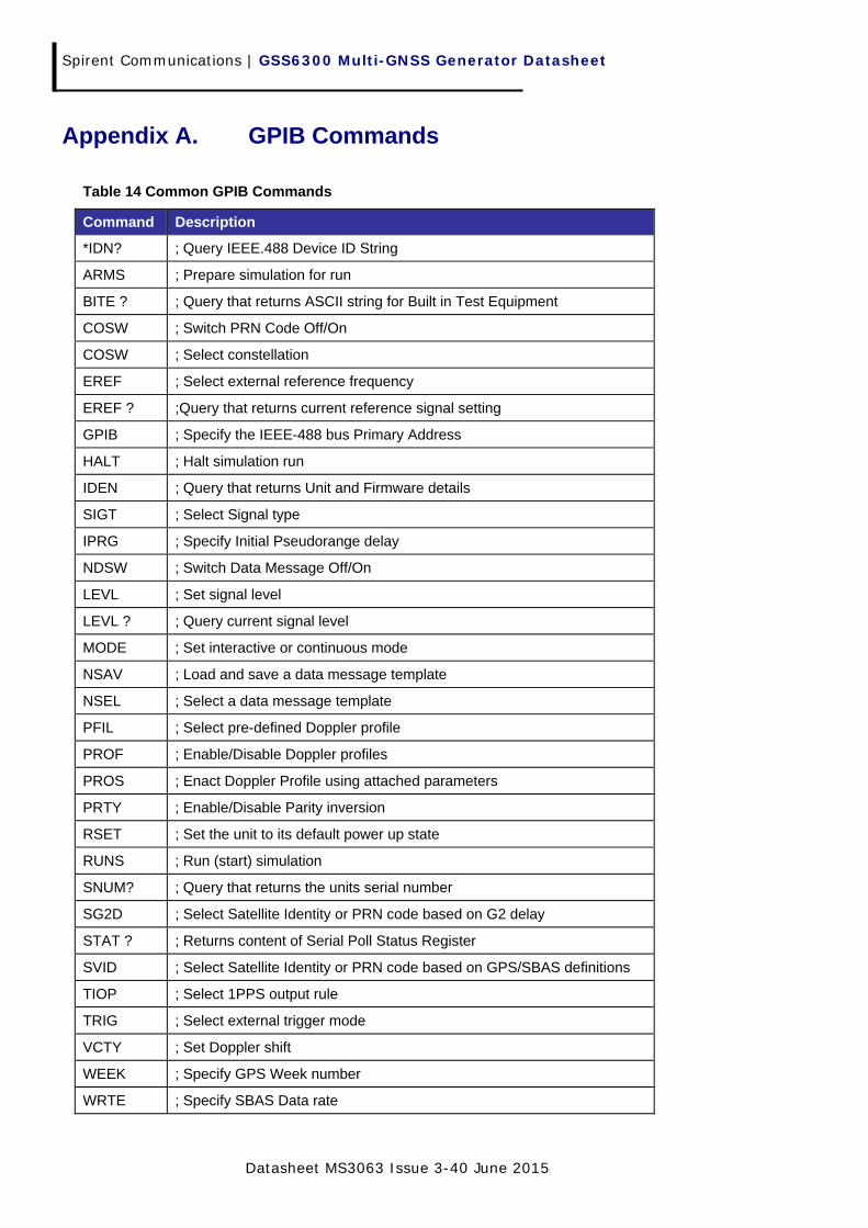
GPIB Control
The IEEE-488 interface is the primary control interface for the signal generator. This interface may be used by a program or application created by the customer. All commands are available on this interface, including those that contain binary data. All the hardware features of the unit may be controlled and varied via this interface industry standard (IEEE-488.1) interface.
APPENDIX A lists the most common of the available GPIB commands.
RS232 Control
The RS-232 interface is available for simple scenario control, such as ARM / RUN / HALT commands. This interface may be used by a program or application created by the customer. This interface is not capable of sending commands that contain binary data.
USB Control
The USB interface is available for customers who wish to use the Spirent USB String Send utility to control the unit using discrete commands.
This interface is not suitable for use with a program or application created by the customer.

Spirent Communications | GSS6300 Multi-GNSS Generator Datasheet
Datasheet MS3063 Issue 3-40 June 2015 17
Environmental and Physical
Table 11 Physical and Electrical
Parameter Value
Dimensions, nominal 449 mm x 386 mm x 89 mm (W x D x H) (17.75 inch x 15.25 inch x 3.5 inch)
Weight Signal Generator (approx)
Approx. 7.0 kg (Approx. 15.5 lb)
Temperature Operating Humidity
+10°C to + 40oC (50°F to 104oF) 40 to 90% RH (non-condensing)
Temperature Storage Humidity
-40°C to + 60oC (-40°F to 140oF) 20 to 90% RH (non-condensing)
Electrical Voltage Power Consumption Frequency
100 to 240 V ac (auto sensed) <72 W 50 to 60 Hz
Figure 4 Typical Front and Rear Panel
Calibration Requirements
The GSS6300 Multi-GNSS Generator must be calibrated at 12 monthly intervals to guarantee performance within specification. The GSS6300 has been designed to be easy to calibrate, requiring a minimum of expertise and time, and all adjusters are available externally on the rear panel of the simulator.
If the GSS6300 is to be used for very accurate absolute frequency measurements it is advisable to either check the absolute frequency of the simulator’s internal frequency oscillator or frequency-lock the unit to an external reference. A calibrated Frequency Counter is required to measure 10.00 MHz with a resolution of 0.05 Hz. A frequency adjust control is provided on the rear panel of the unit.
Spirent Communications | GSS6300 Multi-GNSS Generator Datasheet
Datasheet MS3063 Issue 3-40 June 2015
The output power level may be checked and/or adjusted as necessary (via rear panel) whilst monitoring the higher level RF port specifically provided for this purpose. A calibrated power meter capable of measuring a signal of around -50 dBm at 1.57542 GHz is required.
SAFETY AND EMC CONFORMITY
The GSS6300 Multi-GNSS Generator complies with the Low Voltage Directive (LVD) 2006/95/EC by application of the following harmonised standard:
EN60950-1:2006 Information technology equipment. Safety. General requirements.
The GSS6300 Multi-GNSS Generator complies with the EEC EMC Directive 2004/108/EC by application of the following harmonised standard:
EN61326-1:2006 Electrical Equipment for Measurement, Control and Laboratory Use. EMC Requirements. General requirements.

Spirent Communications | GSS6300 Multi-GNSS Generator Datasheet
Datasheet MS3063 Issue 3-40 June 2015 19
Deliverables
Table 12 Deliverable Items
Item No. Quantity Component Comment
1 1 GSS6300 Multi-GNSS Generator GNSS capability provided depends upon Order Code specified. Please check your quote to confirm that the desired GNSS are included.
2 1 USB Cable For use with SimCHAN
3 1 Power cable Country specific
4 1 CD ROM
SimCHAN software for Windows®
GSS6300 user manual
Default navigation data files
Default correction files for SBAS
Example files for velocity profiles
5 1 License Key Defines the system capability. May be pre-installed or supplied electronically on registration (for upgrades)
6 1 Multi-box cable Optional. Provided by default with product configurations requiring two or more GSS6300 units to be connected together.
Applicable Documents
Table 13 Applicable Documents
Reference Title Issue Date
ICD-GPS-200F
Navstar GPS Space Segment / Navigation User Interfaces Rev D Dec 04
OS SIS ICD Galileo Open Service Signal-in-Space Interface Control Document 1 Feb 10
- GLONASS Interface Control Document 5.0 Sep 02
BDS-SIS-ICD-B1I-1.0 2012-12
BeiDou Signal-in-Space Interface Control Document Open Service B1I 1.0 Dec 12
RTCA-DO229 WAAS MOPS C Nov 01
Spirent Communications | GSS6300 Multi-GNSS Generator Datasheet
Datasheet MS3063 Issue 3-40 June 2015
Appendix A. GPIB Commands
Table 14 Common GPIB Commands
Command Description
*IDN? ; Query IEEE.488 Device ID String
ARMS ; Prepare simulation for run
BITE ? ; Query that returns ASCII string for Built in Test Equipment
COSW ; Switch PRN Code Off/On
COSW ; Select constellation
EREF ; Select external reference frequency
EREF ? ;Query that returns current reference signal setting
GPIB ; Specify the IEEE-488 bus Primary Address
HALT ; Halt simulation run
IDEN ; Query that returns Unit and Firmware details
SIGT ; Select Signal type
IPRG ; Specify Initial Pseudorange delay
NDSW ; Switch Data Message Off/On
LEVL ; Set signal level
LEVL ? ; Query current signal level
MODE ; Set interactive or continuous mode
NSAV ; Load and save a data message template
NSEL ; Select a data message template
PFIL ; Select pre-defined Doppler profile
PROF ; Enable/Disable Doppler profiles
PROS ; Enact Doppler Profile using attached parameters
PRTY ; Enable/Disable Parity inversion
RSET ; Set the unit to its default power up state
RUNS ; Run (start) simulation
SNUM? ; Query that returns the units serial number
SG2D ; Select Satellite Identity or PRN code based on G2 delay
STAT ? ; Returns content of Serial Poll Status Register
SVID ; Select Satellite Identity or PRN code based on GPS/SBAS definitions
TIOP ; Select 1PPS output rule
TRIG ; Select external trigger mode
VCTY ; Set Doppler shift
WEEK ; Specify GPS Week number
WRTE ; Specify SBAS Data rate
Spirent Communications | GSS6300 Multi-GNSS Generator Datasheet
Datasheet MS3063 Issue 3-40 June 2015 21
Command Description
ZCNT ; Specify simulated start time
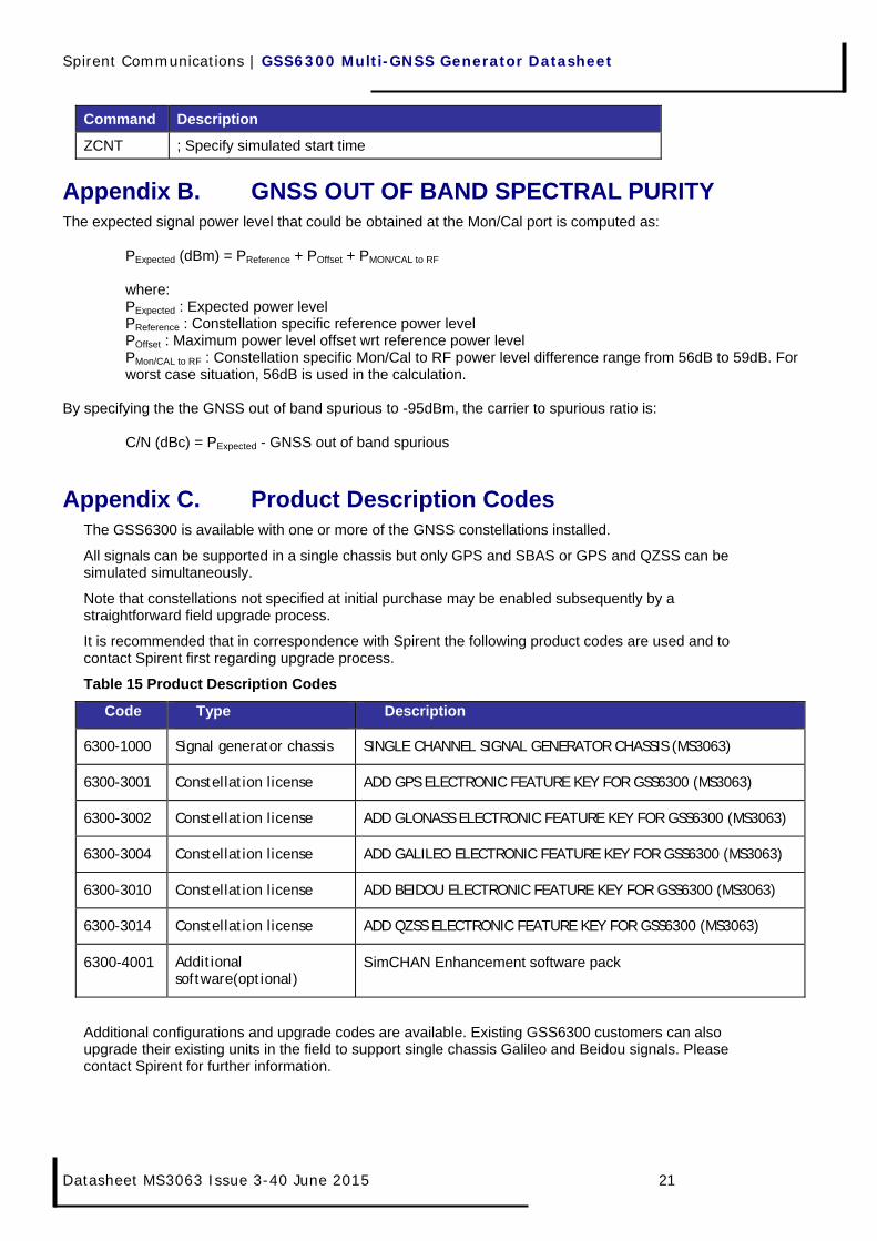
Appendix B. GNSS OUT OF BAND SPECTRAL PURITY The expected signal power level that could be obtained at the Mon/Cal port is computed as:
PExpected (dBm) = PReference + POffset + PMON/CAL to RF where: PExpected : Expected power level PReference : Constellation specific reference power level POffset : Maximum power level offset wrt reference power level PMon/CAL to RF : Constellation specific Mon/Cal to RF power level difference range from 56dB to 59dB. For worst case situation, 56dB is used in the calculation.
By specifying the the GNSS out of band spurious to -95dBm, the carrier to spurious ratio is: C/N (dBc) = PExpected - GNSS out of band spurious
Appendix C. Product Description Codes The GSS6300 is available with one or more of the GNSS constellations installed.
All signals can be supported in a single chassis but only GPS and SBAS or GPS and QZSS can be simulated simultaneously.
Note that constellations not specified at initial purchase may be enabled subsequently by a straightforward field upgrade process.
It is recommended that in correspondence with Spirent the following product codes are used and to contact Spirent first regarding upgrade process.
Table 15 Product Description Codes
Code Type Description
6300-1000 Signal generator chassis SINGLE CHANNEL SIGNAL GENERATOR CHASSIS (MS3063)
6300-3001 Constellation license ADD GPS ELECTRONIC FEATURE KEY FOR GSS6300 (MS3063)
6300-3002 Constellation license ADD GLONASS ELECTRONIC FEATURE KEY FOR GSS6300 (MS3063)
6300-3004 Constellation license ADD GALILEO ELECTRONIC FEATURE KEY FOR GSS6300 (MS3063)
6300-3010 Constellation license ADD BEIDOU ELECTRONIC FEATURE KEY FOR GSS6300 (MS3063)
6300-3014 Constellation license ADD QZSS ELECTRONIC FEATURE KEY FOR GSS6300 (MS3063)
6300-4001 Additional software(optional)
SimCHAN Enhancement software pack
Additional configurations and upgrade codes are available. Existing GSS6300 customers can also upgrade their existing units in the field to support single chassis Galileo and Beidou signals. Please contact Spirent for further information.

Spirent Communications | GSS6300 Multi-GNSS Generator Datasheet
Datasheet MS3063 Issue 3-40 June 2015
This page is intentionally left blank.

Spirent Communications | GSS6300 Multi-GNSS Generator Datasheet
Datasheet MS3063 Issue 3-40 June 2015 23
Spirent Communications plc, Aspen Way, Paignton, Devon TQ4 7QR, UK Tel +44 (0)1803 546300 Fax +44 (0)1803 546301
www.spirent.com/positioning Registered in England Number 00470893
Registered office: Northwood Park, Gatwick Road, Crawley, West Sussex RH10 9XN, UK