Embed Size (px)
Citation preview


DAZ|Studio Artists Guide Page iii
Table of Contents


DAZ|Studio Artists Guide
Table of Contents Page v
CHAPTER 1 : WELCOME 19
What is DAZ|Studio? 19
Create 20
Express 20
Key Features 21
What's New in DAZ|Studio 1.7? 22
Included Documentation 24
Artist Guide 24
Conventions 24
Ordered Procedures 24
Keyboard Entries 24
Commands and Prompts 25
Important Terms 25
Program and Script Code 25
Tips, Cautions, and Notes 25
ReadMe 25
System Requirements 25
Windows 25
Macintosh 26
Need Help? 26
Contacting Technical Support 26
Other DAZ Resources 27
CHAPTER 2 : INSTALLING THE SOFTWARE 29
Windows Installation 29
Macintosh Installation 30
Installing Content Furnished with DAZ|Studio 31
Running DAZ|Studio for the First Time 31
Getting Updates 34
CHAPTER 3 : THE BASICS 37
Starting Your Project 37
Step One: Add a Figure 38
Step Two: Add Clothing 39
Step Three: Add Wings 41
Step Four: Add Hair 41
DAZ|Studio Artists Guide
Page vi Table of Contents
Attaching Clothing 42
Step One: Fit the Dress 44
Step Two: Fit the Wings 46
Step Three: Assign a Parent for the Hair 46
Step Four: Pose the Figure 47
Step Five: Using Morphs to Change Body Shape 48
Using the Render Activity Tab 50
Step One: Render Settings 50
Step Two: Render the Image 51
Step Three: Save the Render 52
Step Four: Save the Scene 52
In Conclusion 53
CHAPTER 4 : LIGHTS! CAMERA! 55
About Lights 55
Using Cameras 55
Step One: Change the Background Color 56
Step Two: Build and Adjust a Spotlight 56
Create the Spotlight 56
Select the faceLight Camera 57
Adjust the Spotlight 58
Frame the Default Camera 60
Step Three ‐ Add a Distant Light 61
Adjust the Perspective View 61
Create the Distant Light 62
Adjust the Light Properties 62
Step Four ‐ Add a Point Light 63
Step Five ‐ Add and Scale a Second Figure 64
Step Six ‐ Tests, Tweaks, and Workflow 65
Adjusting the Lights 66
In Conclusion 67
CHAPTER 5 : USING AND CUSTOMIZING YOUR INTERFACE 71
An Overview of Interface Items 71
Customizing DAZ|Studio 73
The Customize DAZ|Studio Dialog 73
Customizing Shortcuts and Icons 77
Customizing Activity Tabs 77
DAZ|Studio Artists Guide
Table of Contents Page vii
Customizing Menus 79
Customizing Toolbars 80
Customizing Your Layout 81
Using Multiple Monitors 81
Customizing Panes 81
Customizing Tabs 83
Customizing Interface Colors 84
Setting Interface Preferences 85
Saving Your Custom Interface Layout 86
Loading Custom Interface Layouts 87
CHAPTER 6 : COMMAND AND TOOLBAR REFERENCE 89
File Menu Commands 89
The Load Toolbar 89
New 90
Open 90
Merge 90
Save 90
Save As 90
Save Last Render 91
Import 91
Export 92
Exit 92
Edit Menu Commands 92
Undo 93
Redo 93
Delete 93
Delete All Lights 94
Delete All Cameras 94
Copy Settings 94
Paste Settings 94
Backdrop 94
Audio 94
Preferences 94
Customize 94
View Menu Commands 94
Interface Layout 95
Interface Style 95

DAZ|Studio Artists Guide
Page viii Table of Contents
Viewport Layout 96
Tabs 96
Render Menu Commands 98
Create Menu Commands 98
New Camera 99
New Point Light 99
New Distant Light 99
New Spotlight 99
New Null 99
New D‐Former 99
New Primitive 99
Tools Menu Commands 99
Node Selection 100
Rotate 100
Translate 100
Scale 101
Surface Selection 101
PowerPose 101
Spot Render 101
Help Menu Commands 101
DAZ|Studio Quick Start 102
DAZ|Studio Help 102
Online Resources 102
What's This Help 103
About DAZ|Studio 103
About Your Video Card 103
About Installed Plug‐ins 103
Report a Bug 103
CHAPTER 7 : USING AND CREATING MATERIALS 107
Materials, Shaders, and Texture Maps 107
About the Surfaces Tab 108
The Surfaces Tab Options Menu 108
The Surface List 109
Selecting a Single Object 109
Selecting Multiple Objects 110
Copy/Paste Buttons 110
The Basic and Advanced Sub‐tabs 110
DAZ|Studio Artists Guide
Table of Contents Page ix
Basic 111
Advanced 111
Configuring Materials 113
Preparing for the Tutorials 113
Color (Diffuse) 115
Basic Tab 115
Advanced Tab 116
Diffuse Tutorial 116
Highlight (Specular) 117
Basic Tab 117
Advanced Tab 117
Highlight Tutorial 118
Shadow (Ambient) 119
Basic 120
Advanced 120
Opacity 121
Opacity Tutorial 122
Bump Channel 123
Bump Tutorial 124
Displacement Channel 125
Displacement Tutorial 125
Reflection 127
Reflection Tutorial 127
Refraction 129
Refraction Tutorial 130
Lighting Model 131
Saving Materials 132
CHAPTER 8 : THE CONTENT TAB 135
Adding Content for DAZ|Studio 136
Using the Directories Preferences Tab 136
Installing DAZ Content 138
Installing Third‐Party Content 139
Content Viewing and Navigation 139
Content Tab Options 139
Navigating Content Folders 140
Using List View 140
Using Tree View 141
DAZ|Studio Artists Guide
Page x Table of Contents
Maintaining Content 142
Maintaining Folders 143
Content Menu Options 144
Adding Content to Your Scene 144
Content Sub‐Tabs 145
Info Tab 145
Author Tab 145
Adding or Editing Authorship Information 146
Save As Button 146
CHAPTER 9 : VIEWPORTS AND CAMERAS 149
Basic 3D Terminology 149
Axes: Working with 3D on a 2D Screen 149
Orthogonal and Perspective Views or Cameras 150
Orthogonal Cameras 150
Perspective Cameras 152
Customizing Your Viewport Layout 153
Selecting the Active Viewport 155
Changing Cameras 155
DrawStyles 156
Other Viewport Options 157
Adjusting Cameras 158
Using the Camera Controls 158
Creating Your Own Cameras 159
Using the Camera Parameter Dials 160
The Transforms Section 160
The Misc Section 161
The Camera Section 162
CHAPTER 10 : THE SCENE TAB 165
Scene Hierarchy and Tab Controls 165
Using the Scene Tab and Scene List 165
Showing and Hiding Items in the Scene Tab 166
Showing and Hiding Items in the Scene List 167
Selecting All of a Specific Content Type 168
Sorting Content in the Scene Tab 168
Expanding and Collapsing the Entire Tree 169
DAZ|Studio Artists Guide
Table of Contents Page xi
Expanding and Collapsing Portions of the Tree 169
Scene Tab Selection Options 170
Selecting and Navigating Through Objects 170
Creating Parent/Child Relationships 171
Parenting Items in Place 171
Renaming Objects 172
Setting Scene Preferences 172
CHAPTER 11 : THE PARAMETERS TAB 175
Tab Options 175
Setting Parameters 177
Menus and Buttons 178
Common Parameter Settings 178
Translations 178
Rotations 179
Scale 180
Visible and Selectable 181
Cast Shadows 181
Bend 182
Fit To 182
Point At 183
Morphs 183
Hip Type 183
The Numeric Parameter Settings Dialog 184
The Toggle Parameter Settings Dialog 185
Parameters vs. Morphs 186
CHAPTER 12 : THE TIMELINE TAB 187
Animation Basics 187
Breaking it Down 187
Anatomy of the Timeline Tab 187
CHAPTER 13 : OTHER TABS 191
The Help Tab 191
The New at DAZ Tab 191
The Align Tab (Align Ace) 192
Aligning Objects 193
How to Align Objects to Each Other 193

DAZ|Studio Artists Guide
Page xii Table of Contents
How to Align Objects to the Grid 194
Distributing Objects 194
How to Distribute Objects 194
Stacking Objects 195
X‐Axis Alignment Options 195
Y‐Axis Alignment Options 196
Z‐Axis Alignment Options 197
The Tool Tab 198
The D‐Form Tab 199
The PowerPose Tab 199
The Puppeteer Tab 200
CHAPTER 14 : POSING AND MOVING FIGURES 203
Selecting Which Joints to Move 203
Direct Manipulation 203
Manipulation Movement Modes 204
Applying Pose Presets 204
Moving Figures 204
Applying Morphs 204
Applying Clothing Figures 205
Automatic Mode 205
Manual Mode 205
Clothing Tips and Tricks 206
Figure Parameters 206
Root Node Parameters 207
Bones 207
Hip Type 208
Multiple Bones 208
Symmetry 209
Symmetry Preferences 210
CHAPTER 15 : WORKING WITH PROPS 211
Working with Objects 211
Global vs. Local Coordinates 211
Defining an Object's Location (Translation) 212
Rotating Objects 214
Defining an Object's Shape and Size 214
Manipulating/Moving Props 215
DAZ|Studio Artists Guide
Table of Contents Page xiii
Using the Manipulator 215
Selecting Which Prop to Move 216
Applying Morphs 216
Prop Parameters 217
Multiple Props 217
CHAPTER 16 : MORE ABOUT LIGHTS 219
Point Lights 219
Point Light Parameters 219
Distant Lights 220
Distant Light Parameters 221
Spot Lights 222
Spotlight Parameters 222
Manipulating/Moving Lights 224
Selecting Which Light to Move 224
Using the Manipulator 224
Multiple Lights 224
CHAPTER 17 : RENDERING 227
About the DAZ|Studio Renderer 227
Speeding Up Your Renders 227
The Render Settings Window 228
General Tab 228
Speed: 229
Style: 229
Dimensions 229
Timeline 230
Render To 230
Advanced Tab 231
Spot Renders 233
CHAPTER 18 : TOOLS: PLUG-INS AND SCRIPTS 237
A Word About How DAZ|Studio is Built 237
Why Such a Modular Approach? 237
What Kind of Tools Are There? 237
Where to Get Tools 238
What Tools are Included? 238
DAZ|Studio Artists Guide
Page xiv Table of Contents
Using Tools 239
CHAPTER 19 : POWERPOSE 241
The PowerPose Tab 241
Posing Body Parts 241
Using Limits 244
Posing Hand Parts 245
Posing Head Parts 246
The PowerPose Tool Tab 247
Pinning Options 248
Dragging Options 249
Drawing Options 250
Selected Bone Properties 251
CHAPTER 20 : D-FORM 254
How D‐Form Works 254
Anatomy of a D‐Former 254
The D‐Former Base 255
The D‐Former Handle 255
The D‐Former Field 255
D‐Form Tab Options 256
The D‐Form Spline Editor 258
What is a Spline? 259
Out from the Center 259
Give it some ‘oomph’! 260
Working Within the Editor 260
Tutorial: Creating a Head Morph 261
Experiment! 266
Tutorial: A Coronation of One 266
CHAPTER 21 : THE PARAMETERS ORGANIZER 275
Installing the Parameters Organizer 275
Adding and Renaming Parameter Groups 275
CHAPTER 22 : PUPPETEER 277
The Puppeteer Options Menu 278
Using the Edit Mode 278
Using the Preview Mode 279
Using the Record Mode 280

DAZ|Studio Artists Guide
Table of Contents Page xv
Using Layers 281
Layer 1: Turning the Eyes 281
Layer 2: Moving the Brows 282
One More Layer: Head Movement 283
CHAPTER 23 : THE COMPONENTS OF 3D OBJECTS 288
Types of 3D Objects 288
Points (Vertices) 288
Segments (Edges) 288
Lines (Splines) 289
Polygons (Faces/Facets) 289
Objects (Meshes) 289
Material Groups 289
Surfaces 290
CHAPTER 24 : BONES AND HIERARCHIES 292
Bones 292
The Hierarchical Chain 293
Hierarchies 293
Parent/Child Relationships Between Objects 293
CHAPTER 25 : OTHER DAZ PRODUCTS 294
CHAPTER 26 : EULA 295

DAZ|Studio Artists Guide Page 17
Section 1:
Introduction

DAZ|Studio Artists Guide
Chapter 1: Welcome Page 19
Chapter 1 : Welcome
“I found I could say things with color and shapes that I couldn’t say any other way... things I had no words for.” -Georgia O’Keeffe
We would like to take a moment and thank you for acquiring DAZ|Studio; a powerful, friendly tool built for people who love and work with 3D artwork. If you are new to 3D artwork, DAZ|Studio helps make things easier for you to plunge in. If you are a professional looking for solid and easy-to-adapt software, you will find the flexibility and extensibility of DAZ|Studio to be a powerful addition to your workflow. DAZ|Studio makes it easy for you to create high quality images.
What is DAZ|Studio?
Think of DAZ|Studio as a complete virtual photo studio. Lights, cameras, makeup, wardrobe, props, and more are at your fingertips. You create scenes by placing virtual actors (called figures), props, and other elements in the studio. Adjust your lighting, position your cameras, and you have a complete image. The Surfaces Tab in DAZ|Studio allows you to change any object’s color, opacity, roughness, and many other attributes. You can change an actor’s skin color, make any surface into a mirror, make water transparent, turn a rough wool into shimmering silk or lace, and even give a smooth tree trunk a rough bark texture. In contrast, real-world photo or film projects pose challenges. These begin with scouting for places to shoot, and end when you have all of the images or footage you need and then some. Scheduling is a
tricky and costly affair that can go wrong for any number of reasons.
The challenges multiply once the work begins with the crew and models. In order to adjust the lighting, you stop shooting while the crew adjusts, meters, and tests the lights. If you want to change a pine table to a mahogany table, you either get a new table or spend hours refinishing the existing one. If the focus is all wrong, you have to re-shoot the entire scene. We have not even touched on the required paperwork - model releases, copyright research, royalty schedules. Of course, there are other ways to express your art in real life - such as through sketches, oils, and sculpture. Less scheduling and expensive equipment is required, until you make a mistake or find a flaw in the base material. This usually means starting over or living with imperfect results. Let’s face it: real-world art can be unforgiving.
However, what if you could accomplish the following tasks:
Schedule studio time whenever you want Have actors who are always ready when
you are Move cameras, lights, actors, and props
easily Control and change the appearance of
every item in the scene instantly? Achieve excellent results in hours or even
minutes instead of days, weeks, or months
DAZ|Studio makes all of this and more, not only possible, but easy, cost-effective, and fun.
DAZ|Studio Artists Guide
Page 20 Chapter 1: Welcome
Create
DAZ|Studio unleashes creativity in artists, photographers, filmmakers, animators, illustrators, and more. Hobbyists and professionals alike can create impressive images for just about any purpose. With DAZ|Studio, you concentrate on your art, not on extensive (and expensive) setup. Here are just a few of the things you can do with DAZ|Studio:
Add as many people to a scene as you like.
Pose and animate human, animal, alien, and even inanimate figures, down to the smallest detail.
Dress up your figures by adding custom hair and clothing. Further, many hair and clothing items have additional built-in customization.
Place furniture, backgrounds, and other objects in your scene. The variety is almost limitless - your own living room with its usual props (detailed right down to the remote control), or the engine room of a spaceship orbiting Proxima Centauri, or anything in-between. These props add context, realism, and interest to your results.
Place and adjust lights. You can customize brightness, area of illumination, location, direction, color, and gels to achieve the exact effect you’re looking for.
Place and adjust multiple cameras and see your scene from up to four points of view at once. You can select from a variety of viewport layouts and choose
from a complete assortment of orthographic and perspective cameras. This gives you great flexibility and control as you build and adjust your scene.
Change the appearance of any character, prop, or other item in your scene.
Express
DAZ|Studio’s features give you the power to express your creativity in a very practical way. Here are a few examples of ways you can use DAZ|Studio, both personally and professionally:
Hobbyists can create images in any genre - from medieval to contemporary to futuristic.
Book designers and authors can create compelling cover images that capture the book’s essence.
Engineers can test for size, proportion, fit, and ergonomics, all without having to build a single physical prototype or mock-up.
Law enforcement and legal specialists can recreate crime scenes and/or re-enact events for forensic, civil or criminal trial purposes.
Public safety personnel, the military, and adventurers alike can simulate potentially dangerous procedures for training purposes, or for testing, all without putting anyone at risk.
Architects can include people in their concept art, to illustrate how the structures they design interact with occupants and with each other.
DAZ|Studio Artists Guide
Page 21 Chapter 1: Welcome
Filmmakers and animators can create more compelling storyboards during preproduction in less time.
Advertising agencies can build high-quality clip art banks and custom images for their clients’ print ads at a far lower production cost... and without the need for paying royalties or residuals.
Photographers and filmmakers can create professional results that can be composited with their physical scenes, or replace them entirely as imagination and desires warrant. Those who create documentaries can illustrate places and events that no longer exist, or physical concepts otherwise impossible to explain.
Sculptors and graphic artists can conceptualize their work in virtual space, and even use it as part of their bid for contract. They can then use it as a three-dimensional guide while they translate their concepts onto canvas, stone, metal, plaster, and more.
As you can see, DAZ|Studio can do more than just make pretty pictures.
Key Features
DAZ|Studio includes these powerful features:
PC and MAC Support: DAZ|Studio runs on Windows 98SE/2000/Me/XP, and Mac OSX 10.3 and above.
Fully Optimized: DAZ|Studio supports OpenGL acceleration in 3D views, which gives you high-quality real-time lighting,
textures, transparency, anti-aliasing, and depth-of-field. Smart memory optimizations save system resources and boosts performance. The highly flexible Content Tab allows you to handle large amounts of content effortlessly. By taking advantage of the latest technologies, DAZ|Studio gives you amazing power, speed, and ease of use.
Multiple 3D Views: Select one of several included viewport layouts that let you see your scene from up to four angles at once. Change any view to suit your needs at any time using intuitive camera controls. Try that in any real-world studio!
A Highly Flexible User Interface: The user interface allows you to customize layouts, menus, toolbars, shortcuts, and more. Move, shape, change, and manage the UI layout (and behavior) to optimize your workflow.
Dual-monitor support: Users will especially appreciate the ability to spread the application out across both monitors.
Native File Formats: The new .daz, .dsb, and .ds file formats allows both flexibility and built-in encryption to aid in the protection of content creators’ copyright. It allows for a high degree of flexibility but a high amount of speed as well. Built-in on-the-fly zlib compression also makes it easier on your hard drive space.
Import Popular File Formats: DAZ|Studio can import the popular Wavefront Object (*.obj) file format, and all Poser 4 file formats - scenes (.pz3), characters (.cr2)

DAZ|Studio Artists Guide
Page 22 Chapter 1: Welcome
, props (.pp2) , camera (.pp2), light (.lt2), hands (.hd2), hair (.hr2), facial expressions (.fc2), pose presets (.pz2), and their compressed (.**Z) counterparts.
Powerful Rendering Engine: DAZ|Studio uses the RenderMan®-compliant 3Delight renderer (www.3delight.com).
Direct Select: Select any object or material by clicking it directly inside a viewport.
Scene Tab: View your scene hierarchy, select and edit bones or objects, and apply clothing and other properties using this tab.
Parameter Tab: Pose figures and manipulate cameras, props, and scenes as easily as turning the dials in this tab.
Surfaces Tab: Edit any material in your scene, including color, highlight, opacity, reflection, and texture using this tab.
3D Manipulation: Pose figures using intuitive on-screen controls. Set movement limits to define custom ranges of motion.
Multiple Undo/Redo: Move back or forward several steps to correct errors or make changes. The results will always be right where you left them before, so go ahead, experiment! You can always decide to do something different later on.
What's New in DAZ|Studio 1.7?
DAZ|Studio 1.7 includes a sleek, new interface design that is fully customizable. The first thing that you’ll notice is that it looks much cleaner and
brighter. The icons have been moved to areas where they are most needed, and the viewport and camera controls are now located in the viewport so that you can have easy access to them.
NOTE!
One of the most important new features of DAZ|Studio 1.7 is that you can customize the interface to look exactly the way you want it to look. Create new Activity Tabs, menus, and toolbars that work the way you want to work. Add your own shortcuts and toolbar icons. Change the interface colors. Arrange the panes and tabs the way you want them to appear.
Other new interface items include the following:
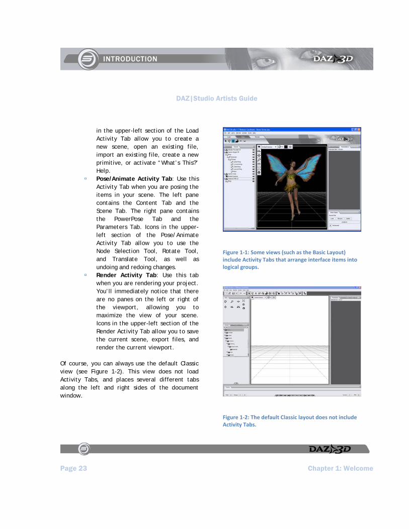
New Interface Design: The default color scheme is now a very light shade of gray with black text, making it much easier to read. In addition, you can choose from a number of different layouts. For example, if you select the Basic Layout (shown in Figure 1-1) you’ll notice three tabs just beneath the Menu Bar. These Activity Tabs place the most commonly used tabs where you need them. There are three tabs in the Basic Layout:
Load Activity Tab: Use this Activity Tab when you are placing items in your scene. The left pane contains the Content Tab, and the right pane contains the New at DAZ Tab. Icons
DAZ|Studio Artists Guide
Page 23 Chapter 1: Welcome
in the upper-left section of the Load Activity Tab allow you to create a new scene, open an existing file, import an existing file, create a new primitive, or activate “What’s This?” Help.
Pose/Animate Activity Tab: Use this Activity Tab when you are posing the items in your scene. The left pane contains the Content Tab and the Scene Tab. The right pane contains the PowerPose Tab and the Parameters Tab. Icons in the upper-left section of the Pose/Animate Activity Tab allow you to use the Node Selection Tool, Rotate Tool, and Translate Tool, as well as undoing and redoing changes.
Render Activity Tab: Use this tab when you are rendering your project. You’ll immediately notice that there are no panes on the left or right of the viewport, allowing you to maximize the view of your scene. Icons in the upper-left section of the Render Activity Tab allow you to save the current scene, export files, and render the current viewport.
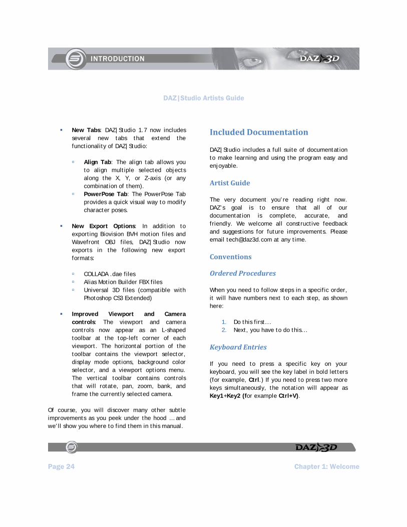
Of course, you can always use the default Classic view (see Figure 1-2). This view does not load Activity Tabs, and places several different tabs along the left and right sides of the document window.
Figure 1‐1: Some views (such as the Basic Layout) include Activity Tabs that arrange interface items into logical groups.
Figure 1‐2: The default Classic layout does not include Activity Tabs.
DAZ|Studio Artists Guide
Page 24 Chapter 1: Welcome
New Tabs: DAZ|Studio 1.7 now includes several new tabs that extend the functionality of DAZ|Studio:
Align Tab: The align tab allows you to align multiple selected objects along the X, Y, or Z-axis (or any combination of them).
PowerPose Tab: The PowerPose Tab provides a quick visual way to modify character poses.
New Export Options: In addition to exporting Biovision BVH motion files and Wavefront OBJ files, DAZ|Studio now exports in the following new export formats:
COLLADA .dae files Alias Motion Builder FBX files Universal 3D files (compatible with
Photoshop CS3 Extended)
Improved Viewport and Camera controls: The viewport and camera controls now appear as an L-shaped toolbar at the top-left corner of each viewport. The horizontal portion of the toolbar contains the viewport selector, display mode options, background color selector, and a viewport options menu. The vertical toolbar contains controls that will rotate, pan, zoom, bank, and frame the currently selected camera.
Of course, you will discover many other subtle improvements as you peek under the hood … and we’ll show you where to find them in this manual.
Included Documentation
DAZ|Studio includes a full suite of documentation to make learning and using the program easy and enjoyable.
Artist Guide
The very document you’re reading right now. DAZ’s goal is to ensure that all of our documentation is complete, accurate, and friendly. We welcome all constructive feedback and suggestions for future improvements. Please email [email protected] at any time.
Conventions
Ordered Procedures
When you need to follow steps in a specific order, it will have numbers next to each step, as shown here:
1. Do this first... 2. Next, you have to do this...
Keyboard Entries
If you need to press a specific key on your keyboard, you will see the key label in bold letters (for example, Ctrl.) If you need to press two more keys simultaneously, the notation will appear as Key1+Key2 (for example Ctrl+V).

DAZ|Studio Artists Guide
Page 25 Chapter 1: Welcome
Commands and Prompts
Screen prompts, menu and window names, fields, buttons, boxes, etc. appear in bold type. The syntax used to demonstrate accessing a palette or submenu is Menu > Submenu. For example Edit > Preferences means that you should open the Edit pull-down menu and then select Preferences to open the Preferences dialog box.
Important Terms
Important terms appear in italics.
Program and Script Code
Program and script code appears in standard fixed font. For example:
cd\letters\business\legal [ENTER]
Tips, Cautions, and Notes
TIP!
Tips contain helpful advice and other information that makes the software easier and more enjoyable to use.
CAUTION!
Cautions warn of potential problems that you will want to avoid.
NOTE!
Notes contain other points worth mentioning.
ReadMe
At the end of the DAZ|Studio installation process, the Readme file will automatically appear. This file includes late-breaking developments and other information that was too recent to be included in the Artist Guide or Install Notes. Please take a few moments to read this information carefully as it may affect how you use DAZ|Studio.
System Requirements
In order to install and run DAZ|Studio, you must have either a Windows PC or Macintosh that meets or exceeds the minimum requirements listed below. Computers that exceed the following specifications will be able to process scenes faster and/or store more content. For processing speed, RAM is the largest contributing factor followed by your processor speed, then your graphics card (for OpenGL renders, but not 3Delight). To store more raw content and/or finished scenes, add hard drive space.
The above recommendations are valid for both Windows PCs and Macintoshes.
Windows
To run DAZ|Studio on a Windows PCs, your computer must meet the following minimum requirements. Check them in Windows’ Device Manager -Control Panel > System > Hardware > Device Manager (Windows 98/2000/XP):
Pentium III processor running at 700 MHz Windows 98SE or above
DAZ|Studio Artists Guide
Page 26 Chapter 1: Welcome
128 MB RAM (if running Windows 98 or ME)
256 MB RAM (if running Windows 2000 or XP)
50 MB hard drive space (for DAZ|Studio installation only). Content requires additional space. DAZ therefore recommends that you reserve at least 350MB for the software and some basic content.
OpenGL-compatible graphics card with at least 128MB of on-card RAM:
Drivers supporting OpenGL 1.1 required, OpenGL 1.5 recommended
NVIDIA GeForce FX series or better cards highly recommended
ATI Radeon series or better cards recommended
32-bit color (“True Color” in Windows’ Display Properties)
Microsoft DirectX 8.1 or above
Macintosh
To run DAZ|Studio on a Macintosh, your computer must meet the following minimum requirements - check them via (Apple Menu) > About This Mac > More Info, which opens the System Profiler:
G4 processor, at 700 MHz or better. OSX 10.3 or above 256 MB RAM 50 MB hard drive space (for DAZ|Studio
installation only). Content requires additional space. DAZ therefore recommends that you reserve at least
350MB for the software and additional content.
OpenGL-compatible graphics card with at least 128MB of on-card RAM:
Drivers supporting OpenGL 1.1 required, OpenGL 1.5 recommended
NVIDIA GeForce FX series or better cards highly recommended
ATI Radeon series or better cards recommended
32-bit color capability (System Preferences > Displays, then select “Millions” under the “Colors:” drop-down menu.)
Need Help?
This manual addresses as many questions about DAZ|Studio as possible. Should you need it, there are several ways to get additional help.
Contacting Technical Support
Need support? Please contact DAZ as follows:
Toll Free Phone: (800) 267-5170 Local Phone: (801) 495-1777 (Our
technical support hours are Monday through Friday, from 9:00 a.m. to 5:00 p.m. Mountain Standard/Daylight Time).
Fax: (801) 495-1787 Online Direct:
http://www.daz3d.com/support/contact_support.php
DAZ|Studio Artists Guide
Page 27 Chapter 1: Welcome
US Mail: 12637 South 265 West, #300, Draper, UT 84020
Other DAZ Resources
Web site: http://www.daz3d.com
Support database: http://www.daz3d.com/support
Community Forums: http://forum.daz3d.com
Tutorials: http://arcana.daz3d.com

DAZ|Studio Artists Guide
Chapter 2: Installing the Software Page 29
Chapter 2 : Installing the Software
This chapter describes the installation process for DAZ|Studio on both Windows and Macintosh computers. Before installing DAZ|Studio, you must read, understand, and agree to the End User License Agreement (“EULA”) and learn how DAZ|Studio protects artists’ copyrights. The EULA appears during DAZ|Studio installation. For your convenience, we have included a print version.
Windows Installation
To install DAZ|Studio on a Windows PC:
1. Double-click the DAZ|Studio Setup icon to start DAZ|Studio Setup.
2. The Setup program informs you that the Microsoft Visual C++ shared libraries are required in order for DAZ|Studio to run. Click OK to perform a search for the required files. Setup installs the files if necessary.
3. If you have a previous installation of DAZ|Studio on your computer, the installer prompts you to uninstall the previous installation. We recommend that you select Yes to avoid potential conflicts. This operation only uninstalls files installed by the previous DAZ|Studio installation. Content (such as figures, etc.) installed by independent installers are not removed. You may also be prompted to remove shared files that are
no longer in use by other software. A dialog appears when the previous installation has been removed. Click OK to continue.
4. The DAZ|Studio Setup screen appears. Click Next to continue.
5. The Welcome dialog appears. Click Next to proceed.
6. The Software License Agreement dialog appears. You must read, understand, and agree to abide by the terms of the DAZ|Studio End User License Agreement (EULA). Indicate your acceptance by clicking Yes. If you would like a hard copy of the EULA for your records, you may click the Print button.
7. The Tell-Ware Agreement appears next. It explains what Tell-Ware is, and asks if you will tell at least two friends about DAZ|Studio. Please select the checkbox indicating that you will, and click Next to continue.
8. The Choose Destination Location dialog appears with the default installation folder selected. DAZ|Studio is installed to the C:\Program Files\DAZ|Studio folder by default. To select a custom location, you may either type in your desired location in the Destination Directory field or click the Browse button to navigate to your desired installation folder. After you choose your desired folder, click Next to proceed.
9. The Select Program Folder dialog appears. This screen determines the program folder that is used in the Windows Start menu. By default, the DAZ Productions\DAZ Studio folder is selected.
DAZ|Studio Artists Guide
Page 30 Chapter 2: Installing the Software
You can also enter a custom folder name or choose a folder from the Existing Folders list. Click Next to continue.
10. The Previous Settings Found dialog appears if you have previously installed DAZ|Studio on your computer. This screen prompts you to search for DAZ|Studio and Poser® content that exists on your hard drive. If you have not made changes to your content folder locations, you may select Use the previous content search results to save time. Select Perform a content search on next activate to perform a search the next time you start DAZ|Studio. After you make your selection, click Next.
11. The Ready to Install dialog informs you that the files will be installed. Click Next. The DAZ|Studio installer copies the program files to the installation folder and updates the Windows registry.
12. Setup asks if you want to place a DAZ|Studio icon on your desktop. Click Yes or No to continue.
13. The Last Minute Notes dialog appears. It contains information too recent to be included in the Artist Guide. Please take a few moments to read this important information, and then click Next to proceed.
14. The Finished dialog box appears. This dialog confirms the successful installation. Check or uncheck the options to launch DAZ|Studio, view the DAZ|Studio Quick Start, or launch the DAZ|Studio ReadMe file, which contains recent information about the program.
Then click Close to complete the installation.
This concludes the DAZ|Studio installation process for Windows.
Macintosh Installation
To install DAZ|Studio on a Macintosh:
1. Unpack the .sit file, and then double-click the DAZ|Studio Setup icon to start DAZ|Studio Setup.
2. The Welcome dialog appears. Click Next to proceed.
3. The Software License Agreement dialog appears. You must read, understand, and agree to abide by the terms of the DAZ|Studio End User License Agreement (EULA). To proceed, you must scroll to the bottom of the agreement to enable the Accept button. Indicate your acceptance by clicking Accept. If you would like a hard copy of the EULA for your records, click the Print button.
4. The Tellware Dialog appears next. It explains what Tellware is, and asks if you will tell at least two friends about DAZ|Studio. Please select the checkbox indicating that you will. Together, we can all make a difference, and continue to help DAZ|Studio grow.
5. The DAZ|Studio Setup dialog appears with the default installation location selected. Click Install to install DAZ|Studio to the default location. If you have a previous version, select Uninstall from the drop-

DAZ|Studio Artists Guide
Chapter 2: Installing the Software Page 31
down menu at top, click Uninstall at the bottom of the screen, and then once uninstalled, re-select Easy Install from the drop-down menu at the top of the window. To select a custom location, you may click the Install Location button (which will list the default volume that DAZ|Studio will install in) to navigate to your desired install location. After selecting your desired location, click Install to proceed.
6. The DAZ|Studio installer now copies the program files to the selected installation folder.
7. A message appears asking if you would like to add DAZ|Studio to the OSX dock. Select Yes to add DAZ|Studio to the OSX dock or No to skip this step.
8. Upon successful installation, a message will appear telling you that if you want DAZ|Studio to run as a slave application (for instance as a slave to Bryce 5.5), you’ll have to restart before the slave behavior takes place. Select OK to end the installation.
9. The Readme file appears in your default web browser after installation. The Readme contains up-to-the-minute information too recent for either the Artist Guide or Install Notes.
Installing Content Furnished with DAZ|Studio
The DAZ|Studio downloads appear after you login and go to your My Account section (under Available Downloads). You should see two files:
The DAZ|Studio Application file is the installer for the program itself. The DAZ|Studio Free Content file installs some content that will help get you started with the application. In fact, you will be using some of this content in the tutorials that follow in Chapters 3 and 4 … so you might want to install them now.
Download the DAZ|Studio Free Content from your account page, and start the installer. When you reach the Content Destination screen (shown in Figure 2-1), select your DAZ Studio Content folder. For Windows users, the path to the folder is C:\Program Files\DAZ\Studio\content.
Figure 2‐1: Choose the path to your DAZ|Studio content folder in the Choose Destination screen.
Running DAZ|Studio for the First Time
When you start DAZ|Studio for the first time, the DAZ|Studio Setup Wizard opens. This wizard

DAZ|Studio Artists Guide
Page 32 Chapter 2: Installing the Software
prompts you to enter author information and set some preferences.
Complete the wizard as follows:
1. In the first screen of the DAZ|Studio Setup Wizard the installer prompts you to register your copy of DAZ|Studio online. It only requires that you have an active, verified account at the DAZ Web site (http://www.daz3d.com). To register the software online, click the Register Online button.
To sign in to an existing account, enter your registered email address and password, and click the Sign In button.
To register a new account, enter a valid email address in the New Customers section and click Register. You will be prompted to enter additional registration information, such as a password, first and last names, community user name, and date of birth. Additional options ask if you’d like to receive the DAZ newsletter, and whether you would like users to search for your wishlist. After you enter the information, click Create Account.
2. After you sign in or create an account, you will be directed to the Software Serial Numbers page in your account screen. When you return to the DAZ|Studio setup wizard, the Author Information screen appears (Figure
2-2Figure 2-2). The wizard prompts to optionally enter your name, email address, and web site URL. You do not have to enter this information to run DAZ|Studio. The information that you enter is contained within files that you save to your hard drive. If you create content for DAZ|Studio, the information you enter can help users contact you with questions or find other information on your web site that can help them use your content. After you optionally enter the information, click Next to continue.
Figure 2‐2: Enter your name, email address, and URL in the Author Information screen. This information is optional.
DAZ|Studio Artists Guide
Chapter 2: Installing the Software Page 33
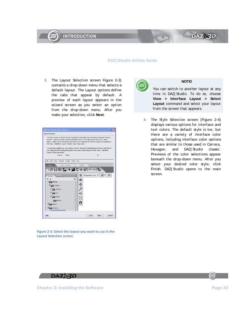
3. The Layout Selection screen Figure 2-3) contains a drop-down menu that selects a default layout. The Layout options define the tabs that appear by default. A preview of each layout appears in the wizard screen as you select an option from the drop-down menu. After you make your selection, click Next.
Figure 2‐3: Select the layout you want to use in the Layout Selection screen.
NOTE!
You can switch to another layout at any time in DAZ|Studio. To do so, choose View > Interface Layout > Select Layout command and select your layout from the screen that appears.
4. The Style Selection screen (Figure 2-4) displays various options for interface and text colors. The default style is Ice, but there are a variety of interface color options, including interface color options that are similar to those used in Carrara, Hexagon, and DAZ|Studio classic. Previews of the color selections appear beneath the drop-down menu. After you select your desired color style, click Finish. DAZ|Studio opens to the main screen.

DAZ|Studio Artists Guide
Page 34 Chapter 2: Installing the Software
Figure 2‐4: The Style Selection screen allows you to select one of several different color schemes.
NOTE!
To select a color scheme at any time, use the View > Interface Style > Select Style command.
Getting Updates
DAZ will continue to evolve and improve DAZ|Studio and release periodic updates. You can check for updates in one of two ways.
Watch for news and updates at the DAZ forums (http://forum.daz3d.com).
Allow DAZ|Studio to do all of the checking for you. Choose Edit > Preferences and select the General tab. Two buttons appear near the bottom of the dialog. The first button allows you to check automatically for updates Daily, Weekly, Monthly, or Never. To check for updates immediately, click Check for Updates Now. If there are updates, DAZ|Studio presents you with the option to install them. Otherwise, you will get a note that there are no available updates at this time.
DAZ|Studio Artists Guide
DAZ|Studio Artists Guide Page 35
Section 2:
Getting Started

DAZ|Studio Artists Guide
Chapter 3: The Basics Page 37
Chapter 3 : The Basics
“Take the attitude of a student, never be too big to ask questions, never know too much to learn something new.”
-Og Mandino
These tutorials will show you the very basics of DAZ|Studio: how to take a basic set of content and turn it into a bit of artwork. This very basic run-through of DAZ|Studio and its tools will help familiarize you with the interface and help you get comfortable with it. As you work through the tutorials, the concepts will become more and more advanced and will build upon the work you have done previously. By the time you finish, you have a pretty scene along with a basic but solid grasp of how to use DAZ|Studio.
To begin, open DAZ|Studio and see what is lurking in there.
Starting Your Project
DAZ|Studio is like a virtual photo studio. The viewport appears in the center and is where you view and manipulate your scene’s content. This is like viewing a room with limitless length, width, and height through a camera lens. You can fill this empty universe with whatever you like. This is the Default Scene.
If you choose a layout other than the Classic layout, you may see Activity Tabs appear directly beneath the Menu bar. For example, if you choose
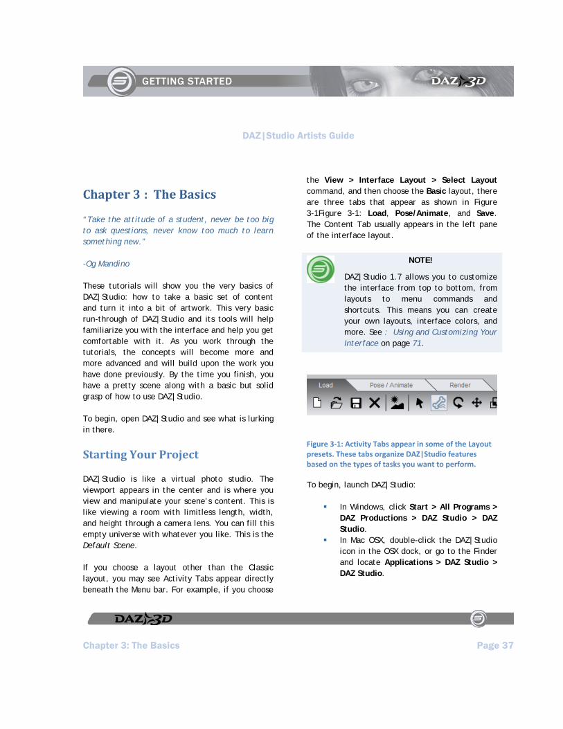
the View > Interface Layout > Select Layout command, and then choose the Basic layout, there are three tabs that appear as shown in Figure 3-1Figure 3-1: Load, Pose/Animate, and Save. The Content Tab usually appears in the left pane of the interface layout.
NOTE!
DAZ|Studio 1.7 allows you to customize the interface from top to bottom, from layouts to menu commands and shortcuts. This means you can create your own layouts, interface colors, and more. See : Using and Customizing Your Interface on page 71.
Figure 3‐1: Activity Tabs appear in some of the Layout presets. These tabs organize DAZ|Studio features based on the types of tasks you want to perform.
To begin, launch DAZ|Studio:
In Windows, click Start > All Programs > DAZ Productions > DAZ Studio > DAZ Studio.
In Mac OSX, double-click the DAZ|Studio icon in the OSX dock, or go to the Finder and locate Applications > DAZ Studio > DAZ Studio.

DAZ|Studio Artists Guide
Page 38 Chapter 3: The Basics
Step One: Add a Figure
The first time you start DAZ|Studio, the Content Tab appears in the left part of the screen when you choose the Classic layout, or if you select the Load Activity Tab in the Basic (Figure 3-2Figure 3-2) or Advanced layout.
The Content Tab stores all of the content that you have available to use in your scenes. Think of the Content Tab as a virtual storeroom where you keep all of your things. The right pane in the Load Activity Tab displays the New at DAZ Tab, which shows the newest weekly freebie and new content releases that may be of interest to you.
NOTE!
You can view your content in one of two ways: List View or Tree View. See Content Viewing and Navigation on page 139.
Figure 3‐2: Use the Content Tab to add content to your DAZ|Studio scene.
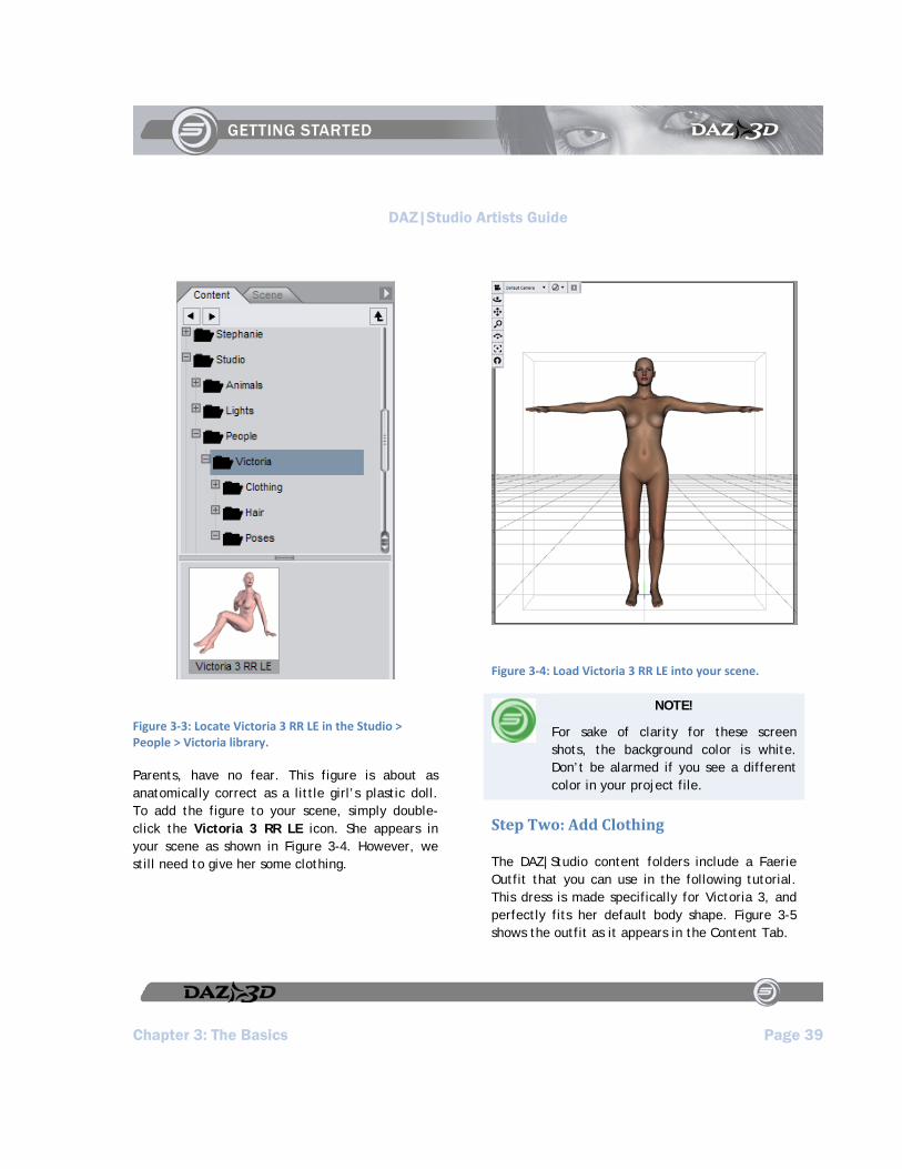
Use the Content Tab to make your little universe not so empty. You should see a directory tree in the Content Tab. Select Studio > People > Victoria to locate the Victoria 3 RR LE figure shown in Figure 3-3Figure 3-3.
DAZ|Studio Artists Guide
Chapter 3: The Basics Page 39
Figure 3‐3: Locate Victoria 3 RR LE in the Studio > People > Victoria library.
Parents, have no fear. This figure is about as anatomically correct as a little girl’s plastic doll. To add the figure to your scene, simply double-click the Victoria 3 RR LE icon. She appears in your scene as shown in Figure 3-4. However, we still need to give her some clothing.
Figure 3‐4: Load Victoria 3 RR LE into your scene.
NOTE!
For sake of clarity for these screen shots, the background color is white. Don’t be alarmed if you see a different color in your project file.
Step Two: Add Clothing
The DAZ|Studio content folders include a Faerie Outfit that you can use in the following tutorial. This dress is made specifically for Victoria 3, and perfectly fits her default body shape. Figure 3-5 shows the outfit as it appears in the Content Tab.
DAZ|Studio Artists Guide
Page 40 Chapter 3: The Basics
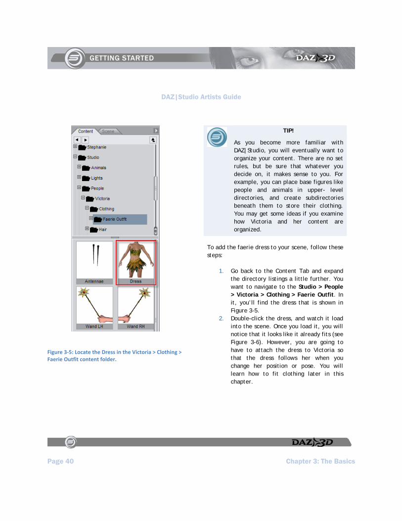
Figure 3‐5: Locate the Dress in the Victoria > Clothing > Faerie Outfit content folder.
TIP!
As you become more familiar with DAZ|Studio, you will eventually want to organize your content. There are no set rules, but be sure that whatever you decide on, it makes sense to you. For example, you can place base figures like people and animals in upper- level directories, and create subdirectories beneath them to store their clothing. You may get some ideas if you examine how Victoria and her content are organized.
To add the faerie dress to your scene, follow these steps:
1. Go back to the Content Tab and expand the directory listings a little further. You want to navigate to the Studio > People > Victoria > Clothing > Faerie Outfit. In it, you’ll find the dress that is shown in Figure 3-5.
2. Double-click the dress, and watch it load into the scene. Once you load it, you will notice that it looks like it already fits (see Figure 3-6). However, you are going to have to attach the dress to Victoria so that the dress follows her when you change her position or pose. You will learn how to fit clothing later in this chapter.
DAZ|Studio Artists Guide
Chapter 3: The Basics Page 41
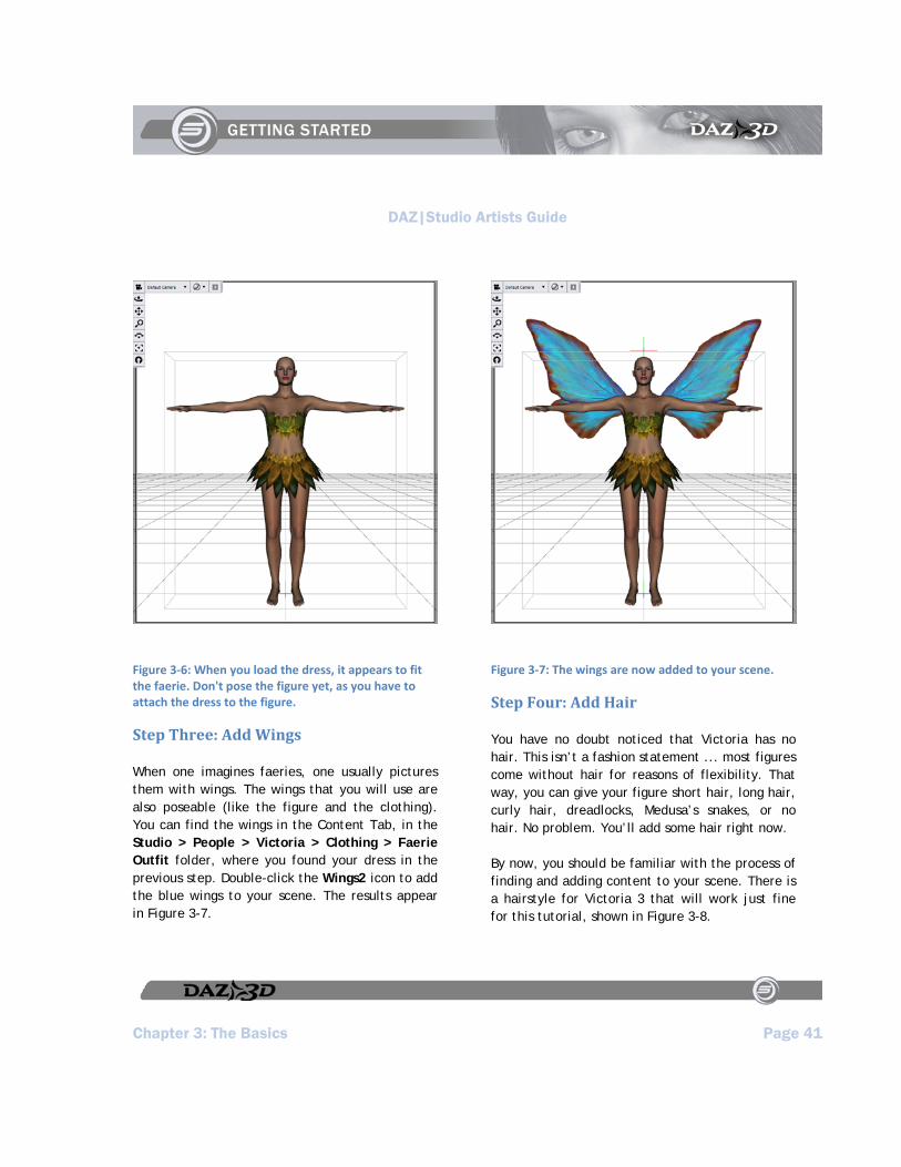
Figure 3‐6: When you load the dress, it appears to fit the faerie. Don't pose the figure yet, as you have to attach the dress to the figure.
Step Three: Add Wings
When one imagines faeries, one usually pictures them with wings. The wings that you will use are also poseable (like the figure and the clothing). You can find the wings in the Content Tab, in the Studio > People > Victoria > Clothing > Faerie Outfit folder, where you found your dress in the previous step. Double-click the Wings2 icon to add the blue wings to your scene. The results appear in Figure 3-7.
Figure 3‐7: The wings are now added to your scene.
Step Four: Add Hair
You have no doubt noticed that Victoria has no hair. This isn’t a fashion statement ... most figures come without hair for reasons of flexibility. That way, you can give your figure short hair, long hair, curly hair, dreadlocks, Medusa’s snakes, or no hair. No problem. You’ll add some hair right now.
By now, you should be familiar with the process of finding and adding content to your scene. There is a hairstyle for Victoria 3 that will work just fine for this tutorial, shown in Figure 3-8.
DAZ|Studio Artists Guide
Page 42 Chapter 3: The Basics
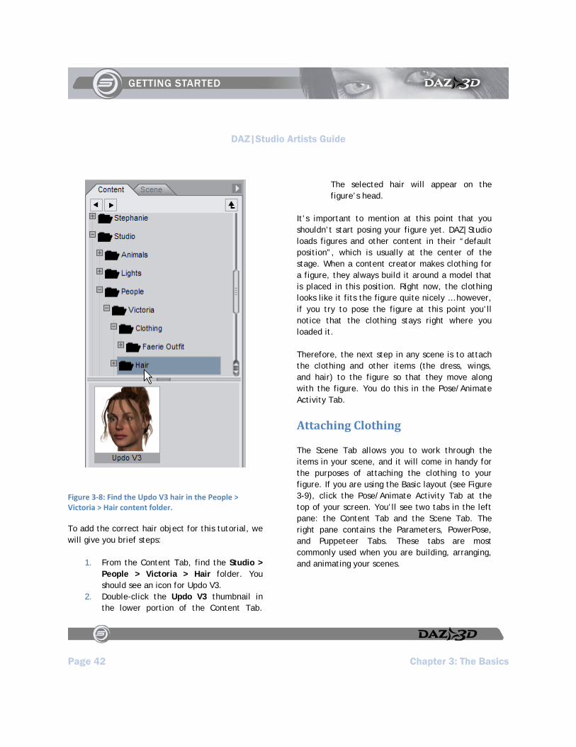
Figure 3‐8: Find the Updo V3 hair in the People > Victoria > Hair content folder.
To add the correct hair object for this tutorial, we will give you brief steps:
1. From the Content Tab, find the Studio > People > Victoria > Hair folder. You should see an icon for Updo V3.
2. Double-click the Updo V3 thumbnail in the lower portion of the Content Tab.
The selected hair will appear on the figure’s head.
It’s important to mention at this point that you shouldn’t start posing your figure yet. DAZ|Studio loads figures and other content in their “default position”, which is usually at the center of the stage. When a content creator makes clothing for a figure, they always build it around a model that is placed in this position. Right now, the clothing looks like it fits the figure quite nicely … however, if you try to pose the figure at this point you’ll notice that the clothing stays right where you loaded it.
Therefore, the next step in any scene is to attach the clothing and other items (the dress, wings, and hair) to the figure so that they move along with the figure. You do this in the Pose/Animate Activity Tab.
Attaching Clothing
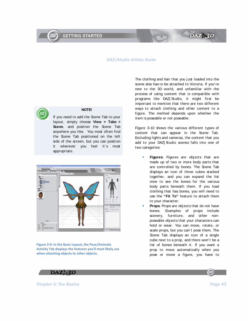
The Scene Tab allows you to work through the items in your scene, and it will come in handy for the purposes of attaching the clothing to your figure. If you are using the Basic layout (see Figure 3-9), click the Pose/Animate Activity Tab at the top of your screen. You’ll see two tabs in the left pane: the Content Tab and the Scene Tab. The right pane contains the Parameters, PowerPose, and Puppeteer Tabs. These tabs are most commonly used when you are building, arranging, and animating your scenes.
DAZ|Studio Artists Guide
Chapter 3: The Basics Page 43
NOTE!
If you need to add the Scene Tab to your layout, simply choose View > Tabs > Scene, and position the Scene Tab anywhere you like. You most often find the Scene Tab positioned on the left side of the screen, but you can position it wherever you feel it’s most appropriate.
Figure 3‐9: In the Basic Layout, the Pose/Animate Activity Tab displays the features you'll most likely use when attaching objects to other objects.
The clothing and hair that you just loaded into the scene also has to be attached to Victoria. If you’re new to the 3D world, and unfamiliar with the process of using content that is compatible with programs like DAZ|Studio, it might first be important to mention that there are two different ways to attach clothing and other content to a figure. The method depends upon whether the item is poseable or not poseable.
Figure 3-10 shows the various different types of content that can appear in the Scene Tab. Excluding lights and cameras, the content that you add to your DAZ|Studio scenes falls into one of two categories:
Figures: Figures are objects that are made up of two or more body parts that are controlled by bones. The Scene Tab displays an icon of three cubes stacked together, and you can expand the list view to see the bones for the various body parts beneath them. If you load clothing that has bones, you will need to use the “Fit To” feature to attach them to your character.
Props: Props are objects that do not have bones. Examples of props include scenery, furniture, and other non-poseable objects that your characters can hold or wear. You can move, rotate, or scale props, but you can’t pose them. The Scene Tab displays an icon of a single cube next to a prop, and there won’t be a list of bones beneath it. If you want a prop to move automatically when you pose or move a figure, you have to

DAZ|Studio Artists Guide
Page 44 Chapter 3: The Basics
parent it to the figure that wears or holds the prop.
Figure 3‐10: Several different types of content can appear in the Scene Tab.
In the sections that follow, you will learn how to use these features to attach the dress, wings, and hair to the faerie.
Step One: Fit the Dress
In order to fit the Faerie Dress to Victoria, you first switch to the Pose/Animate Activity Tab, shown in the following figure. Once in the Pose/Animate Activity Tab, you should see the Parameters Tab on the right side of the screen. It may initially appear behind the PowerPose Tab ... if so, simply click the Parameters Tab to bring it to the foreground as shown in Figure 3-11.
NOTE!
If you don’t see the Parameters Tab, choose the View > Tabs > Parameters command to unhide it. Then you can drag and drop the tab to arrange it anywhere you like.
Figure 3‐11: The Parameters Tab is used to assign various settings to the selected object.
DAZ|Studio Artists Guide
Chapter 3: The Basics Page 45
TIP!
In the Scene Tab, everything loads from bottom to top by default - the first item loads (then the Default Camera), then the next item loaded sits on top of the first in the list, and so on. So, if you ever want to select something in a really huge scene but don’t want to click on it in the viewport, just recall when you added it, and look in that part of the list. If you just added it, it will sit right on top. If you added it very early in the scene, it will be towards the bottom of the list.
To fit the faerie dress to Victoria, follow these steps:
1. Click the Scene Tab, which appears directly behind the Content Tab on the left side of your screen. When the Scene Tab opens, you’ll see five items in there: Victoria (shown as “Victoria RR LE”) on the bottom, then the Default Camera, Faerie Dress, Faerie Wings2 PP, and the hair on top.
2. Click Faerie Dress in the Scene tab to select it as the current object.
3. Now, click the Parameters Tab (on the right side of your screen) to view the parameters of the faerie dress.
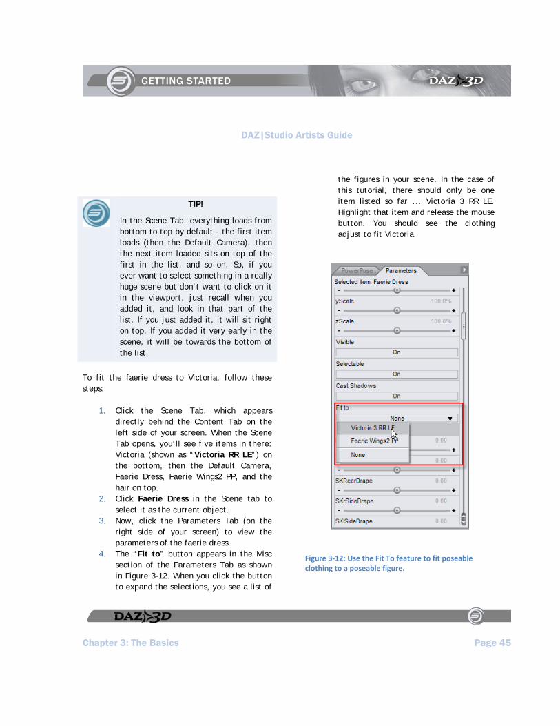
4. The “Fit to” button appears in the Misc section of the Parameters Tab as shown in Figure 3-12. When you click the button to expand the selections, you see a list of
the figures in your scene. In the case of this tutorial, there should only be one item listed so far ... Victoria 3 RR LE. Highlight that item and release the mouse button. You should see the clothing adjust to fit Victoria.
Figure 3‐12: Use the Fit To feature to fit poseable clothing to a poseable figure.

DAZ|Studio Artists Guide
Page 46 Chapter 3: The Basics
TIP!
You can change the name of the scene item into something friendlier - just click on the name within the Scene Tab, click on it again after roughly half a second of time, and type in whatever new name for the item you want. Then, for the change to take effect, just hit Enter.
Step Two: Fit the Wings
The wings are also a poseable figure (they contain bones), so you have to use the Fit To feature to attach them to Victoria as well.
To fit the faerie wings to Victoria, follow these steps:
1. Return to the Scene Tab, and select Faerie Wings2 PP.
2. Now, click the Parameters Tab (on the right side of your screen) to view the parameters of the faerie dress.
3. The “Fit to” button appears in the bottom section of the Parameters Tab. Select Victoria 3 RR LE (see Figure 3-13). Highlight that item and release the mouse button to fit the wings to Victoria.
Figure 3‐13: You also need to use the Fit To feature on the Faerie's wings.
Step Three: Assign a Parent for the Hair
Like clothing, hair is figure-specific. Each hair object is usually designed to work with a specific figure. Some content creators create hair that loads as a figure and has moveable parts to style the hair. In these cases, you can use the “Fit To” feature to attach hair to the figure. Most commonly, however, the hair is a prop that you must attach to a parent object. Most often, the parent object for hair is the head of the figure. This way, when you move the figure’s head, the hair follows.
To assign a parent to the Updo Hair, follow these steps:
1. Remember that the Victoria figure appears in the Scene Tab as Victoria 3 RR LE (unless you changed the name). You can use one of the following methods to select her head:
Click Victoria’s head (not the hair) in the viewport.

DAZ|Studio Artists Guide
Chapter 3: The Basics Page 47
Expand the Victoria 3 RR LE tree in the Scene Tab. Follow the hierarchy down from Hip, to Abdomen, to Chest, to Neck, and finally to Head.
2. With the tree properly expanded, select the hair object from the top of the scene list. Click and drag the hair down with your mouse until it is directly over the Head entry. Then release the mouse button. The Hair entry will then move itself down underneath the Head as shown in Figure 3-14. This indicates that the hair is now a child object to Victoria’s head (children appear beneath their parents in the hierarchy tree). Now you will notice as you pose and move the figure that the hair will retain its proper position and distance relative to the head.
Figure 3‐14: After you expand the Victoria 3 RR LE branch in the Scene tab, drag the hair downward and drop it over the part marked "Head."
Step Four: Pose the Figure
So far, we’ve added a figure to our scene, and given our figure some clothes and a head of hair. Now, let’s give our figure some personality and movement. However, before we begin, let’s quickly describe what poses and morphs do.
Poses are the simple manipulation of what are known as joints within a figure. For example, you can bend a figure’s forearm to get the same kind
DAZ|Studio Artists Guide
Page 48 Chapter 3: The Basics
of movement as when you move your own forearm to bend at the elbow.
You can manipulate joints in several different ways:
Use your mouse to manipulate body parts in the viewport.
Select the body part and use the General sliders in the Parameters Tab to twist, bend, or otherwise turn the joint appropriately.
Use the PowerPose Tab to manipulate the pose of a figure with dots that correspond to each body part that you can pose.
Apply a pose preset file that poses the figure automatically. This is the most popular option for those who are new to DAZ|Studio.
To give you an idea of how a pose preset works, let’s get Victoria to do something other than stand around with her arms sticking out:
1. In the Scene Tab, select Victoria 3 RR LE as the current object. Make sure you set the root object, and not one of her body parts.
2. Switch to the Content Tab, which should be directly behind the Scene Tab.
3. Find and select the Studio > People > Victoria > Poses > Faerie folder. You’ll notice a variety of poses within it.
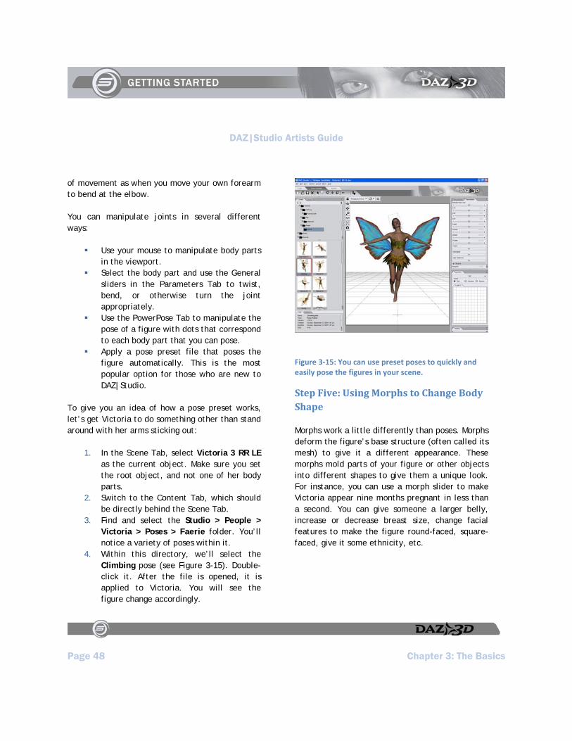
4. Within this directory, we’ll select the Climbing pose (see Figure 3-15). Double-click it. After the file is opened, it is applied to Victoria. You will see the figure change accordingly.
Figure 3‐15: You can use preset poses to quickly and easily pose the figures in your scene.
Step Five: Using Morphs to Change Body Shape
Morphs work a little differently than poses. Morphs deform the figure’s base structure (often called its mesh) to give it a different appearance. These morphs mold parts of your figure or other objects into different shapes to give them a unique look. For instance, you can use a morph slider to make Victoria appear nine months pregnant in less than a second. You can give someone a larger belly, increase or decrease breast size, change facial features to make the figure round-faced, square-faced, give it some ethnicity, etc.
DAZ|Studio Artists Guide
Chapter 3: The Basics Page 49
NOTE!
Morphs are not always available with figures. Some figures have morphs built into them, while others have morph packages available for purchase or download separately.
To give you an idea of how a morph works, we’ll start with something simple. Since faeries are usually slender little things, let’s give Victoria a bit of instant weight-loss:
1. To begin, select Victoria RR LE in the Scene Tab if necessary. Select the root of the figure, and not one of the bones.
2. Move to the Parameters Tab at the right side of the screen. Scroll down until you get to the Morphs section, which is usually near the bottom of the Parameters list. Locate the Skinny slider.
3. Change the Skinny slider setting while you keep an eye on Victoria in the main viewport. You will see her lose weight right before your eyes. Make the setting whatever you want it to be (our example uses a setting of .9). You can change this slider setting in one of three ways:
Click or drag your mouse left or right in the slider
Click one of the arrow keys on either end of the dial
Right-click (Windows) or click and hold (Mac) within the middle of the slider area. Type in a value, and then press [Enter].
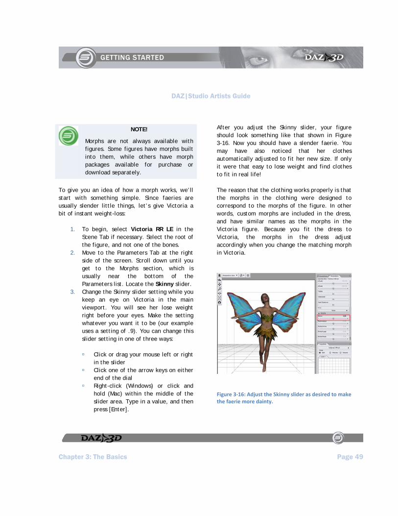
After you adjust the Skinny slider, your figure should look something like that shown in Figure 3-16. Now you should have a slender faerie. You may have also noticed that her clothes automatically adjusted to fit her new size. If only it were that easy to lose weight and find clothes to fit in real life!
The reason that the clothing works properly is that the morphs in the clothing were designed to correspond to the morphs of the figure. In other words, custom morphs are included in the dress, and have similar names as the morphs in the Victoria figure. Because you fit the dress to Victoria, the morphs in the dress adjust accordingly when you change the matching morph in Victoria.
Figure 3‐16: Adjust the Skinny slider as desired to make the faerie more dainty.

DAZ|Studio Artists Guide
Page 50 Chapter 3: The Basics
NOTE!
Note that not all clothing items contain morphs, but the better ones usually do. When morphs are included in the clothing, the developers usually state so in their documentation or promotional material.
Using the Render Activity Tab
If you are new to 3D software, you might not be aware that the viewport only displays a preview of how your final image should look. Most 3D software programs don’t display the “final results” until after you render it. During the rendering process, the software looks at all of the elements in your scene. It performs calculations that determine the appearance or placement of materials, lights, shadows, highlights, reflections, and more. In this final exercise, you’ll turn your first tutorial into a picture.
Now you'll learn about the Render Activity Tab, shown in Figure 3-17. Again, this Activity Tab appears when you choose the Basic Layout. The Render Tab appears in the right pane.
NOTE!
If you prefer not to use the Render Activity Tab, you can render your file at any time and in any view using the Render > Render command.
Figure 3‐17: The Basic Layout includes a Render Activity Tab that removes left and right panes.
Step One: Render Settings
Don’t worry yet if your scene doesn’t look exact, centered, or perfect (we’ll be working to perfect the image in the next chapter). All we want to do for the time being is to make sure that Victoria is in the scene, that she has some clothing on, some hair, that she has something other than the default pose and shape, and that the wings are attached and fitted to her.
To set your render settings, locate the Render Tab in the right pane (or choose the Render > Render Settings command if it does not appear). The Render Settings options presented in either case are shown in Figure 3-18.
DAZ|Studio Artists Guide
Chapter 3: The Basics Page 51
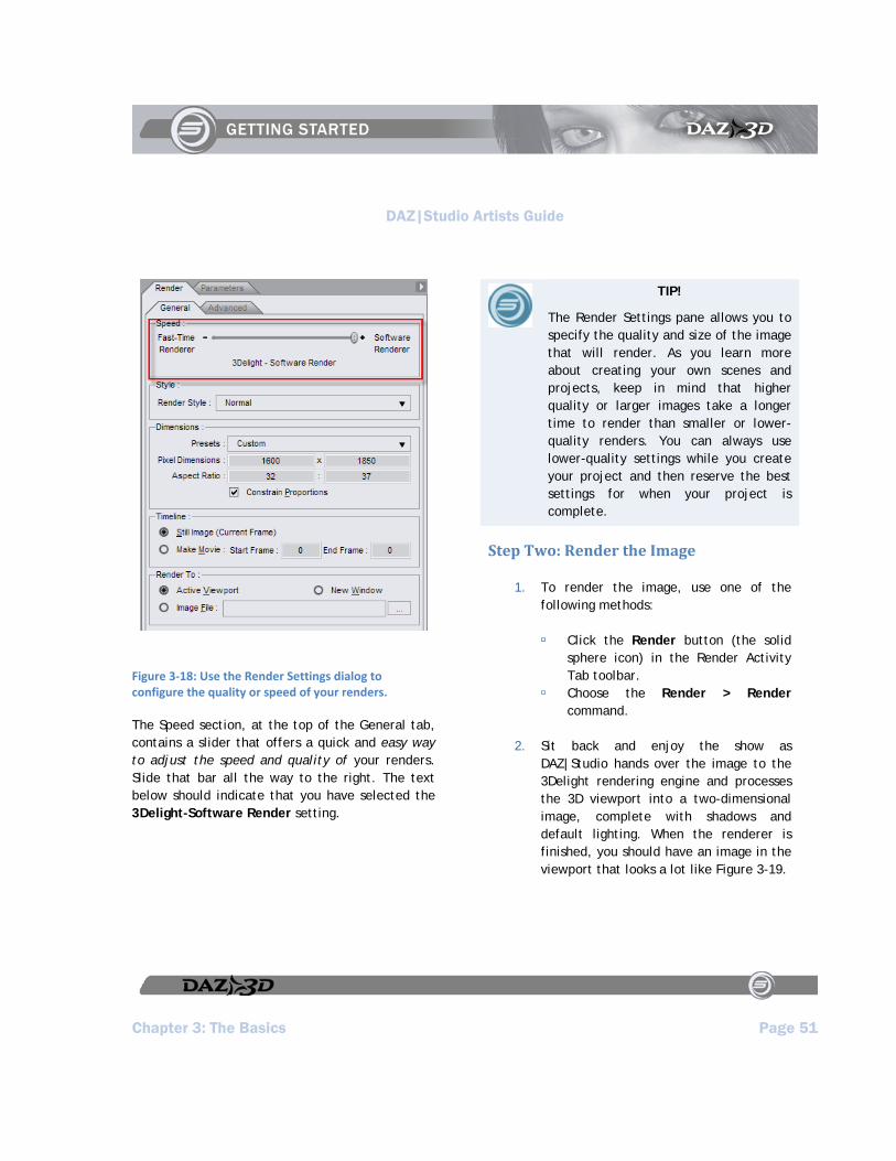
Figure 3‐18: Use the Render Settings dialog to configure the quality or speed of your renders.
The Speed section, at the top of the General tab, contains a slider that offers a quick and easy way to adjust the speed and quality of your renders. Slide that bar all the way to the right. The text below should indicate that you have selected the 3Delight-Software Render setting.
TIP!
The Render Settings pane allows you to specify the quality and size of the image that will render. As you learn more about creating your own scenes and projects, keep in mind that higher quality or larger images take a longer time to render than smaller or lower-quality renders. You can always use lower-quality settings while you create your project and then reserve the best settings for when your project is complete.
Step Two: Render the Image
1. To render the image, use one of the following methods:
Click the Render button (the solid sphere icon) in the Render Activity Tab toolbar.
Choose the Render > Render command.
2. Sit back and enjoy the show as DAZ|Studio hands over the image to the 3Delight rendering engine and processes the 3D viewport into a two-dimensional image, complete with shadows and default lighting. When the renderer is finished, you should have an image in the viewport that looks a lot like Figure 3-19.

DAZ|Studio Artists Guide
Page 52 Chapter 3: The Basics
Figure 3‐19: A rendered image is more detailed than a preview image.
Step Three: Save the Render
If you want to save the rendered image so far, choose the File > Save Last Render command. The Save Image dialog prompts you to enter a file name and choose the file type. You can save to JPG, PNG, TIF, or BMP (Windows Bitmap) format. Save the image to the folder of your choice.
Step Four: Save the Scene
Now that we have a basic scene to work on later, let’s save the file:
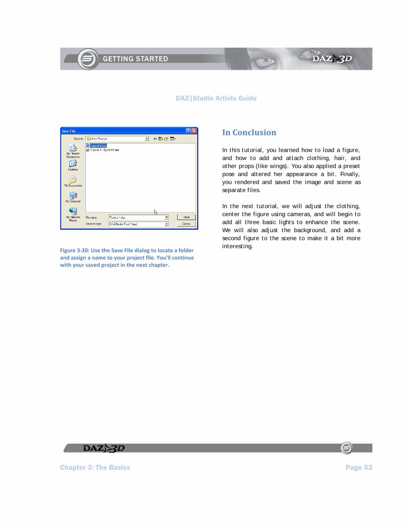
1. Choose the File > Save As > Scene command. The Save File dialog shown in Figure 3-20 appears.
2. DAZ|Studio automatically selects DAZ|Studio Files (*.daz) as the file type for Windows users. This file type saves your DAZ|Studio scenes. In addition, the save location automatically defaults to the Studio > Content > People > Victoria folder, so you can add the saved scene to your Victoria content library and open the scene through the Content Tab. If you desire, you can select a folder of your own choosing.
3. Assign a name for your file. Mac users can add the .daz suffix onto the filename for convenience.
NOTE!
Save this scene wherever you want to, but remember where you saved it, since we’ll begin from this point in the next chapter.
DAZ|Studio Artists Guide
Chapter 3: The Basics Page 53
Figure 3‐20: Use the Save File dialog to locate a folder and assign a name to your project file. You'll continue with your saved project in the next chapter.
In Conclusion
In this tutorial, you learned how to load a figure, and how to add and attach clothing, hair, and other props (like wings). You also applied a preset pose and altered her appearance a bit. Finally, you rendered and saved the image and scene as separate files.
In the next tutorial, we will adjust the clothing, center the figure using cameras, and will begin to add all three basic lights to enhance the scene. We will also adjust the background, and add a second figure to the scene to make it a bit more interesting.

DAZ|Studio Artists Guide
Chapter 4: Lights! Camera! Page 55
Chapter 4 : Lights! Camera!
In the last tutorial, we settled on the basic mechanics of loading figures into a scene, applying basic settings, and rendering the results. Now, we’re going to use a few other basic tools found within DAZ|Studio to make the image into something much more visually pleasing, and to give it a little meaning.
About Lights
Lighting is one of the most important things you’ll set up within a 3D scene. It affects the mood and amount of drama you inject into your artwork. Ask any artist, photographer, or filmmaker, and you will find that lighting is at the very top of their artistic and technical priorities when assembling a scene (especially with photographers.) Lighting plays a subtle but powerful role in enhancing or taking from the colors of everything within a scene. It gives the viewer a good idea as to where they are and even what time of day it may be. The bright and constant fluorescent lights of an office cubicle, the warm reddish glow of a sunset, the harsh retina-etching contrast of bright and dark in Outer Space, the otherworldly lights of some medieval torture chamber... lighting plays one of the largest roles in your work, and can easily make or break your final result.
DAZ|Studio was set from the beginning to have flexible and powerful lighting capabilities. DAZ|Studio itself comes with three types of lights. By the time you complete this tutorial, you will use all three lights to effect:
Spotlights shine light from a specific direction. Your scene will contain a Spotlight that provides the main light and draws attention to our figure’s upper body as she flies. This light will be set to cast shadows on the scene.
Distant Lights provide uniform lighting, similar to the sun. In this project, a Distant Light will shine from underneath to fill in the dark areas just a little, and give the scene a subtle touch of color to subdue the light.
Point Lights shine light in all directions. These are typically used to apply emphasis, or to portray anything from light bulbs to campfires. This tutorial adds a Point Light, which will add special effect when we add a companion for our little Faerie.
TIP!
You can move and aim lights just like cameras, making it fast and easy to put them into place.
Using Cameras
Cameras in DAZ|Studio operate just like any basic consumer camera, but come with two SLR-grade camera options that might interest you.
You can set Focal length (in mm), which is like twisting an SLR camera lens to set your zoom.
You can also set Focal Distance (which allows you, for instance, to focus on just

DAZ|Studio Artists Guide
Page 56 Chapter 4: Lights! Camera!
the subject’s face while blurring out everything behind it.)
Step One: Change the Background Color
To begin, open the saved scene from the last tutorial, and switch to the Pose/Animate Activity Tab. In the first part of this tutorial you will change the background color so that the lighting in the scene will be more dramatic. You can change the background color using the Viewport and Camera tools that are located in the upper-left corner of your viewport. Click the options menu arrow (Figure 4-1) and choose Background Color to open a color selector (Figure 4-2), which should be the same as the color picker in your operating system. Change the color to black and click OK to exit the color picker. Your background should now be black.
Figure 4‐1: Use the Viewport Background Color icon to change the background color to black.
Figure 4‐2: Select a background color from your standard system color picker.
Step Two: Build and Adjust a Spotlight
Up to this point, you have been viewing your scene through the default light setup provided with DAZ|Studio. There is so much more that you can do to make your scenes more dramatic through lighting. To begin, you’ll add and position a Spotlight for dramatic effect. This will delete the existing default light, but you won’t need it anyway.
Create the Spotlight
To create a new Spotlight for your scene, choose the Create > New Spotlight command. The Create New Spotlight dialog opens, with the name Spotlight 1 pre-assigned. For this tutorial, name

DAZ|Studio Artists Guide
Chapter 4: Lights! Camera! Page 57
the light faceLight as shown in Figure 4-3. Then click the Accept button at the bottom of the dialog box to rename the light.
Figure 4‐3: After you assign a name to your spotlight, click Accept to create the new light.
No doubt, you’re sitting there scratching your head and wondering why everything went dark after you added the light (Figure 4-4). Don’t be alarmed, you didn’t do anything wrong. The light is there, it’s just not shining in the right direction.
Figure 4‐4: Don't be alarmed if your light makes the scene go black. You still have to point the light.
Select the faceLight Camera
The easiest way to point the light is to look through the light while you move its position. Go up to the Camera Selection Button at the top-left corner of the viewport. Select the faceLight as shown in Figure 4-5.
While it probably doesn’t look like much right now, you’re now looking at the scene through the faceLight camera. The white line you see in the middle of the screen is the floor, because the camera loads at floor level. You’ll also notice that

DAZ|Studio Artists Guide
Page 58 Chapter 4: Lights! Camera!
the figure is not in view. In the next part of the tutorial we will aim the faceLight, which currently sits on the floor between her feet and points back and away from the figure. The trick is to move and point that light to where we need it.
Figure 4‐5: Select the faceLight camera from the camera selector menu. You'll look through the light to see exactly where it's pointing.
Adjust the Spotlight
The Viewport and Camera Controls (Figure 4-6) appear in the upper-left corner of your viewport window. These controls include camera icons that allow you to move, rotate, and pan any camera, along with controls that also allow you to point the camera to selected objects.
Figure 4‐6: Use the Viewport and Camera controls to switch between viewports and choose which camera you use to view your scene.
We will use the camera controls to move the faceLight into position:
1. Locate the Zoom Camera control icon (third icon down on the left side of the control panel). While your mouse is over it, hold down the left mouse button and push the mouse upwards. Keep moving the camera upward until you see the figure’s left and right fingers near the top of the screen. Then release the mouse button.
2. Now you will move the figure’s head into the viewport. To do so, select the Pan Camera control (the second icon on the left side of the control panel). Again, hold down the left mouse button, and pull the mouse downward. The camera rises upward, making the figure appear to
DAZ|Studio Artists Guide
Chapter 4: Lights! Camera! Page 59
move downward. Keep going until you have can see the entire figure in your viewport.
3. Now you need to rotate the light so that it shines down and at the figure’s face. Select the Rotate Camera icon (the first icon on the left). Left-click and pull the mouse down to rotate the camera around the figure. Right-click and pull the mouse to rotate the camera in place. Move the camera until you’re pointing right at her face. You should also see how the light affects the figure in the viewport.
4. As you rotate the camera you might discover that you’ll need to adjust the Zoom and Pan a little more. Continue to use the camera controls in the View tab until you get the lighting just the way you like. Use the other controls as needed until you have all of her in view, looking downwards at her face.
5. Before we consider this light finished, you have a couple of additional things to set in the Parameters tab. With the faceLight camera still selected, adjust the following settings in the Shadow portion of the Parameters Tab:
Click the Shadow Type button, and choose Deep Shadow Map.
To start, set the Shadow Softness to around 2%. You may want to increase or decrease this setting to taste after you do a test render.
The Shadow Bias setting controls the amount of gradient within the shadow area. Initially, you can set this to around 3.
6. In the Light portion of the Parameters Tab, adjust the following settings to your own preferences:
Make sure that Illumination is set to On.
The default light color is 255, 255, 255, which is a pure white. Leave this at the default value.
Turn the Intensity slider to the left to dim the light, or toward the right to make it brighter. For our example, we reduce it to 77%.
Move the Spread Angle setting toward the left to decrease the angle and narrow the light in to a more specific region. Move the slider toward the right to create a light that fills a wider area. Because we’ve named this light faceLight, the intent is to focus on her face. In the example shown in Figure 4-7, the Spread Angle is set to around 60.

DAZ|Studio Artists Guide
Page 60 Chapter 4: Lights! Camera!
Figure 4‐7: After you adjust the position and other settings for the light, your scene has proper lighting.
Frame the Default Camera
Now that you have some practice in moving a camera, you can go back to adjust the Default Camera, and create your render:
1. Select the Default Camera from the camera list at the top of the viewport.
2. Use the camera controls in the View tab to frame the entire figure into the viewport. There is a great way to start the process:
Go to the Scene tab, and select all items in your scene except the faceLight. Then click the Frame button in the camera controls to center the camera on your scene.
Use the Zoom camera control to move your figure closer to you. Left-click and drag to Dolly Zoom the camera, making the objects appear larger or smaller in your view. Right-click and drag to Focal Zoom the camera to change its focus
When you are finished, you should have a scene that looks something like Figure 4-8. Of course, you can continue to adjust the camera view and lighting to your own taste.
You can render your scene again at this point if desired. When doing so, you might notice that the render takes a little bit longer. A dialog informs you that DAZ|Studio is creating a shadow map for the spotlight. This shadow map is used to determine where the shadows are supposed to fall in your scene. After the calculations are complete, you see the render.

DAZ|Studio Artists Guide
Chapter 4: Lights! Camera! Page 61
Figure 4‐8: Switch to the Default camera and render your scene to see the effects of the spotlight.
Step Three Add a Distant Light
Though you can add and adjust a Distant Light using the same procedures that you used for the Spotlight, you are going to learn a different way to approach it. This time, you’ll apply an existing camera setting to a new light when you create it. This method offers an advantage: it points the new light right where you want it to point when you build it.
Adjust the Perspective View
A Distant Light is usually used as a generalized “sun” type of light. In this tutorial you will use it for effect by placing it lower in the scene and pointing it upwards. You’ll also soften the light so that it doesn’t overpower the scene.
To create the Distant Light, follow these steps:
1. Select Perspective View from the Viewport and Camera controls in the upper-left corner of the viewport.
2. Use the icons in the Viewport and Camera controls to position the Perspective Camera so that it points up at the figure from underneath, as shown in Figure 4-9. You should only need to use the Rotate Camera icon.
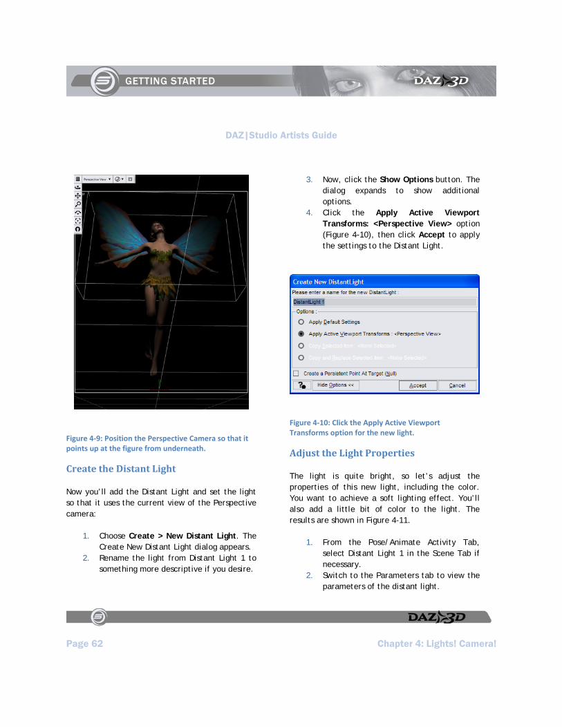
DAZ|Studio Artists Guide
Page 62 Chapter 4: Lights! Camera!
Figure 4‐9: Position the Perspective Camera so that it points up at the figure from underneath.
Create the Distant Light
Now you’ll add the Distant Light and set the light so that it uses the current view of the Perspective camera:
1. Choose Create > New Distant Light. The Create New Distant Light dialog appears.
2. Rename the light from Distant Light 1 to something more descriptive if you desire.
3. Now, click the Show Options button. The dialog expands to show additional options.
4. Click the Apply Active Viewport Transforms: <Perspective View> option (Figure 4-10), then click Accept to apply the settings to the Distant Light.
Figure 4‐10: Click the Apply Active Viewport Transforms option for the new light.
Adjust the Light Properties
The light is quite bright, so let’s adjust the properties of this new light, including the color. You want to achieve a soft lighting effect. You’ll also add a little bit of color to the light. The results are shown in Figure 4-11.
1. From the Pose/Animate Activity Tab, select Distant Light 1 in the Scene Tab if necessary.
2. Switch to the Parameters tab to view the parameters of the distant light.
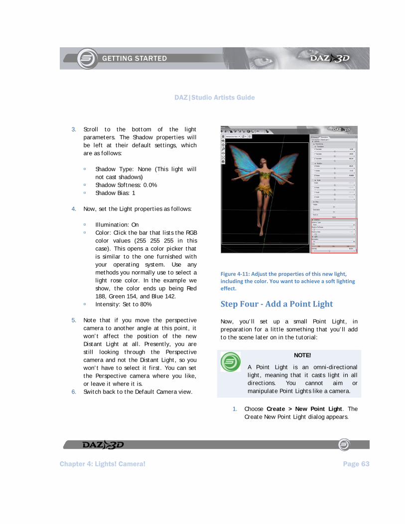
DAZ|Studio Artists Guide
Chapter 4: Lights! Camera! Page 63
3. Scroll to the bottom of the light parameters. The Shadow properties will be left at their default settings, which are as follows:
Shadow Type: None (This light will not cast shadows)
Shadow Softness: 0.0% Shadow Bias: 1
4. Now, set the Light properties as follows:
Illumination: On Color: Click the bar that lists the RGB
color values (255 255 255 in this case). This opens a color picker that is similar to the one furnished with your operating system. Use any methods you normally use to select a light rose color. In the example we show, the color ends up being Red 188, Green 154, and Blue 142.
Intensity: Set to 80%
5. Note that if you move the perspective camera to another angle at this point, it won’t affect the position of the new Distant Light at all. Presently, you are still looking through the Perspective camera and not the Distant Light, so you won’t have to select it first. You can set the Perspective camera where you like, or leave it where it is.
6. Switch back to the Default Camera view.
Figure 4‐11: Adjust the properties of this new light, including the color. You want to achieve a soft lighting effect.
Step Four Add a Point Light
Now, you’ll set up a small Point Light, in preparation for a little something that you’ll add to the scene later on in the tutorial:
NOTE!
A Point Light is an omni-directional light, meaning that it casts light in all directions. You cannot aim or manipulate Point Lights like a camera.
1. Choose Create > New Point Light. The Create New Point Light dialog appears.
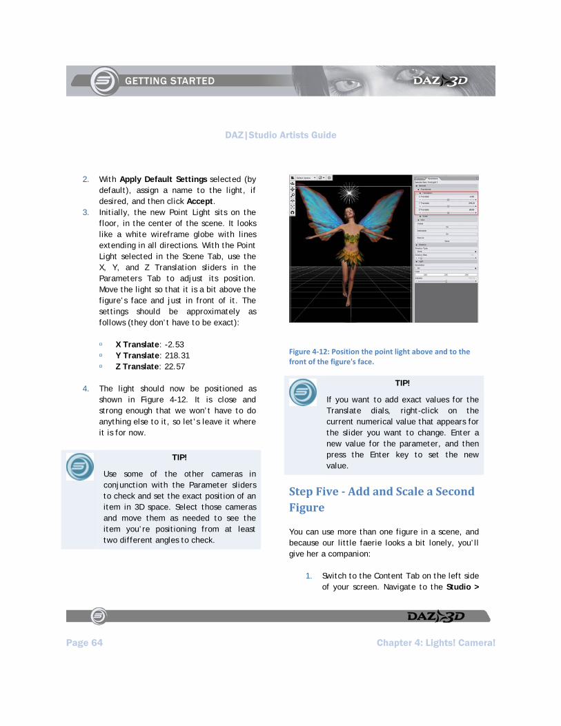
DAZ|Studio Artists Guide
Page 64 Chapter 4: Lights! Camera!
2. With Apply Default Settings selected (by default), assign a name to the light, if desired, and then click Accept.
3. Initially, the new Point Light sits on the floor, in the center of the scene. It looks like a white wireframe globe with lines extending in all directions. With the Point Light selected in the Scene Tab, use the X, Y, and Z Translation sliders in the Parameters Tab to adjust its position. Move the light so that it is a bit above the figure’s face and just in front of it. The settings should be approximately as follows (they don’t have to be exact):
X Translate: -2.53 Y Translate: 218.31 Z Translate: 22.57
4. The light should now be positioned as shown in Figure 4-12. It is close and strong enough that we won’t have to do anything else to it, so let’s leave it where it is for now.
TIP!
Use some of the other cameras in conjunction with the Parameter sliders to check and set the exact position of an item in 3D space. Select those cameras and move them as needed to see the item you’re positioning from at least two different angles to check.
Figure 4‐12: Position the point light above and to the front of the figure's face.
TIP!
If you want to add exact values for the Translate dials, right-click on the current numerical value that appears for the slider you want to change. Enter a new value for the parameter, and then press the Enter key to set the new value.
Step Five Add and Scale a Second Figure
You can use more than one figure in a scene, and because our little faerie looks a bit lonely, you’ll give her a companion:
1. Switch to the Content Tab on the left side of your screen. Navigate to the Studio >
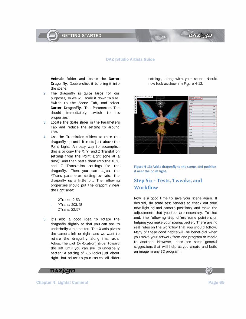
DAZ|Studio Artists Guide
Chapter 4: Lights! Camera! Page 65
Animals folder and locate the Darter Dragonfly. Double-click it to bring it into the scene.
2. The dragonfly is quite large for our purposes, so we will scale it down to size. Switch to the Scene Tab, and select Darter DragonFly. The Parameters Tab should immediately switch to its properties.
3. Locate the Scale slider in the Parameters Tab and reduce the setting to around 15%.
4. Use the Translation sliders to raise the dragonfly up until it rests just above the Point Light. An easy way to accomplish this is to copy the X, Y, and Z Translation settings from the Point Light (one at a time), and then paste them into the X, Y, and Z Translation settings for the dragonfly. Then you can adjust the YTrans parameter setting to raise the dragonfly up a little bit. The following properties should put the dragonfly near the right area:
XTrans: -2.53 YTrans: 203.48 ZTrans: 22.57
5. It’s also a good idea to rotate the dragonfly slightly so that you can see its underbelly a bit better. The X-axis pivots the camera left or right, and we want to rotate the dragonfly along that axis. Adjust the xrot (X-Rotation) slider toward the left until you can see its underbelly better. A setting of -15 looks just about right, but adjust to your tastes. All slider
settings, along with your scene, should now look as shown in Figure 4-13.
Figure 4‐13: Add a dragonfly to the scene, and position it near the point light.
Step Six Tests, Tweaks, and Workflow
Now is a good time to save your scene again. If desired, do some test renders to check out your new lighting and camera positions, and make the adjustments that you feel are necessary. To that end, the following step offers some pointers on helping you make your scenes better. There are no real rules on the workflow that you should follow. Many of these good habits will be beneficial when you move your artwork from one program or media to another. However, here are some general suggestions that will help as you create and build an image in any 3D program:
DAZ|Studio Artists Guide
Page 66 Chapter 4: Lights! Camera!
It is usually a good idea to stop once in awhile and save your work. Remember, you’re working with computers and we all know that there are occasions where something goes wrong. You could lose power, or experience a system crash. When you save your projects frequently, your work won’t totally go to waste.
Save your works-in-progress after every four or five large tasks within DAZ|Studio, or just before you run a test or final render. Other good times to save are right before you export a scene or setting file. In addition, you definitely want to save your project before you try something new.
After you add or adjust lighting or surface materials, run a test render to see exactly how the lights look, how well the figures interact within a scene, or if the eyes are pointed correctly.
While the render is in progress, stand up and move your legs a bit. Go get a cup of coffee, a snack, or other little things while the scene is saving to disk.
Look over your render critically. Note what you need to fix, and fix the issues before you proceed further.
After you make your changes, render again. You can render the full scene, or use the Spot Render Tool to render only the area that is affected by your changes. Once again, look to see if any additional changes are needed. If you’re satisfied with the fixes, continue with the rest of your project.
Adjusting the Lights
You might notice after you render your scene that the lighting needs some adjustment. Here are the problem areas that you might notice:
The scene looks a little flat. One reason is because the Distant Light is too strong and it washes out the shadows of the main faceLight.
You can barely see the dragonfly against the black background. This probably means that you need to adjust the Point Light.
To improve the lighting, follow these steps:
1. From the Scene Tab, select Distant Light 1. Reduce the Intensity slider in the Parameters Tab to 35%. That’s about all you’ll need to do to fix the flatness in the image.
2. Now select Point Light 1 in the Scene Tab.
3. It will help if you look at things from another camera view. From the view selection menu above the upper-left corner of the viewport, choose Left View. You’ll immediately notice why the dragonfly doesn’t stand out. The Point Light is behind the dragonfly.
4. Use the Z Translate slider to move Point Light 1 in front of the dragonfly. Set it to around 80.
5. Switch back to the Default Camera and render your scene again. You’ll notice now that the dragonfly is much more visible, but the light is too bright and is
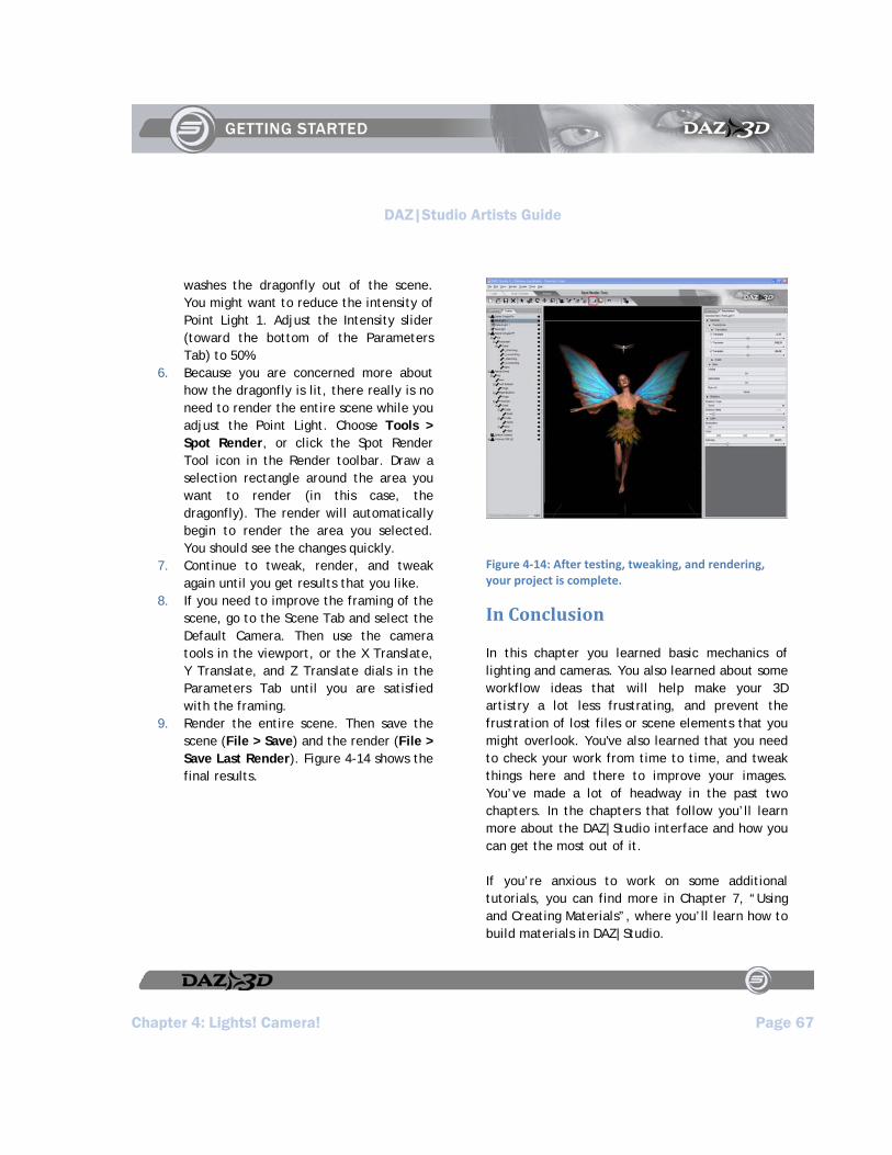
DAZ|Studio Artists Guide
Chapter 4: Lights! Camera! Page 67
washes the dragonfly out of the scene. You might want to reduce the intensity of Point Light 1. Adjust the Intensity slider (toward the bottom of the Parameters Tab) to 50%.
6. Because you are concerned more about how the dragonfly is lit, there really is no need to render the entire scene while you adjust the Point Light. Choose Tools > Spot Render, or click the Spot Render Tool icon in the Render toolbar. Draw a selection rectangle around the area you want to render (in this case, the dragonfly). The render will automatically begin to render the area you selected. You should see the changes quickly.
7. Continue to tweak, render, and tweak again until you get results that you like.
8. If you need to improve the framing of the scene, go to the Scene Tab and select the Default Camera. Then use the camera tools in the viewport, or the X Translate, Y Translate, and Z Translate dials in the Parameters Tab until you are satisfied with the framing.
9. Render the entire scene. Then save the scene (File > Save) and the render (File > Save Last Render). Figure 4-14 shows the final results.
Figure 4‐14: After testing, tweaking, and rendering, your project is complete.
In Conclusion
In this chapter you learned basic mechanics of lighting and cameras. You also learned about some workflow ideas that will help make your 3D artistry a lot less frustrating, and prevent the frustration of lost files or scene elements that you might overlook. You've also learned that you need to check your work from time to time, and tweak things here and there to improve your images. You’ve made a lot of headway in the past two chapters. In the chapters that follow you’ll learn more about the DAZ|Studio interface and how you can get the most out of it.
If you’re anxious to work on some additional tutorials, you can find more in Chapter 7, “Using and Creating Materials”, where you’ll learn how to build materials in DAZ|Studio.

DAZ|Studio Artists Guide
DAZ|Studio Artists Guide Page 69
Section 3:
Menus and Commands


DAZ|Studio Artists Guide
Chapter 5: Using and Customizing Your Interface Page 71
Chapter 5 : Using and Customizing Your Interface
It took me 40 years to find out that painting is not sculpture.”
-Paul Cezanne
DAZ|Studio 1.7 allows you to customize the interface on a grand scale. You can customize colors, menus, and toolbars. You can create your own Activity Tabs and show the controls you want to appear in them. You can create new menus that contain items that you frequently use. In short, with DAZ|Studio 1.7, you can work exactly the way you want to work.
An Overview of Interface Items
In Chapters 3 and 4, you were introduced to the new Activity Tabs that appear in DAZ|Studio: the Load Activity Tab, the Pose/Animate Activity Tab, and the Render Activity Tab. Common to these tabs are several other types of menu commands, toolbars, viewports, panes, and tabs. Figure 5-1 shows a typical arrangement of these various elements.
Figure 5‐1: The components of the DAZ|Studio Interface.
Briefly, the various parts of the interface serve the following functions:
TIP!
By default, DAZ|Studio loads with one viewport. You can view your scene using up to four viewports at once. In addition, DAZ|Studio gives you control over several viewport properties such as size, location, and selected camera. Refer to Chapter 9: Viewports and Cameras for more information.
Activity Tabs: Click one of these tabs to display the various panes and controls that you will commonly use when you Load, Pose, or Render your DAZ|Studio scenes.
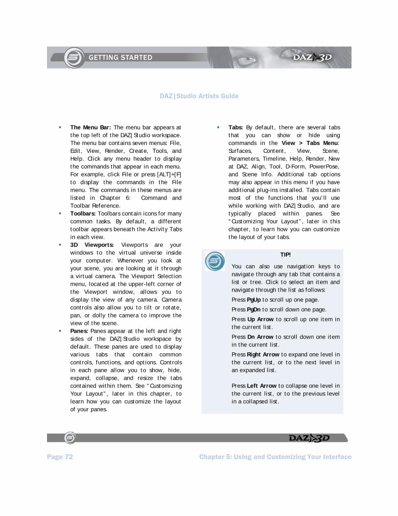
DAZ|Studio Artists Guide
Page 72 Chapter 5: Using and Customizing Your Interface
The Menu Bar: The menu bar appears at the top left of the DAZ|Studio workspace. The menu bar contains seven menus: File, Edit, View, Render, Create, Tools, and Help. Click any menu header to display the commands that appear in each menu. For example, click File or press [ALT]+[F] to display the commands in the File menu. The commands in these menus are listed in Chapter 6: Command and Toolbar Reference.
Toolbars: Toolbars contain icons for many common tasks. By default, a different toolbar appears beneath the Activity Tabs in each view.
3D Viewports: Viewports are your windows to the virtual universe inside your computer. Whenever you look at your scene, you are looking at it through a virtual camera. The Viewport Selection menu, located at the upper-left corner of the Viewport window, allows you to display the view of any camera. Camera controls also allow you to tilt or rotate, pan, or dolly the camera to improve the view of the scene.
Panes: Panes appear at the left and right sides of the DAZ|Studio workspace by default. These panes are used to display various tabs that contain common controls, functions, and options. Controls in each pane allow you to show, hide, expand, collapse, and resize the tabs contained within them. See “Customizing Your Layout”, later in this chapter, to learn how you can customize the layout of your panes.
Tabs: By default, there are several tabs that you can show or hide using commands in the View > Tabs Menu: Surfaces, Content, View, Scene, Parameters, Timeline, Help, Render, New at DAZ, Align, Tool, D-Form, PowerPose, and Scene Info. Additional tab options may also appear in this menu if you have additional plug-ins installed. Tabs contain most of the functions that you’ll use while working with DAZ|Studio, and are typically placed within panes. See “Customizing Your Layout”, later in this chapter, to learn how you can customize the layout of your tabs.
TIP!
You can also use navigation keys to navigate through any tab that contains a list or tree. Click to select an item and navigate through the list as follows:
Press PgUp to scroll up one page.
Press PgDn to scroll down one page.
Press Up Arrow to scroll up one item in the current list.
Press Dn Arrow to scroll down one item in the current list.
Press Right Arrow to expand one level in the current list, or to the next level in an expanded list.
Press Left Arrow to collapse one level in the current list, or to the previous level in a collapsed list.

DAZ|Studio Artists Guide
Chapter 5: Using and Customizing Your Interface Page 73
Customizing DAZ|Studio
The Edit > Customize command opens the Customize DAZ|Studio dialog, which allows you to customize virtually any element in DAZ|Studio so that you can arrange things exactly the way you want them to be. If you are new to DAZ|Studio, you might want to wait a bit before jumping in and customizing your interface … otherwise tutorials and such will seem a bit confusing because you may not remember where you placed your panes, commands, and toolbars.
You’ll probably find as you learn more about DAZ|Studio that you want to locate panes or toolbars in a different place. You may need an Activity Tab that displays all of the items you need when you modify materials on an object, or when you create an animation. With the Edit > Customize command you can do all this and more.
To open the Customize DAZ|Studio dialog, choose Edit > Customize. You’ll see the dialog shown in Figure 5-2.
Figure 5‐2: Use the Customize DAZ|Studio dialog to configure layouts, styles, menus, and commands exactly the way you want them to be.
The Customize DAZ|Studio Dialog
The left portion of the Customize DAZ|Studio dialog displays an Actions List that includes all of the commands in the DAZ|Studio menus and submenus. This also includes custom actions that you have created yourself when you save your own presets. Where shortcuts apply to a command, the shortcut is listed to the right side of the command menu.
Notice that some of the commands have their associated icons next to them. While you can add commands that do not have icons, it will be
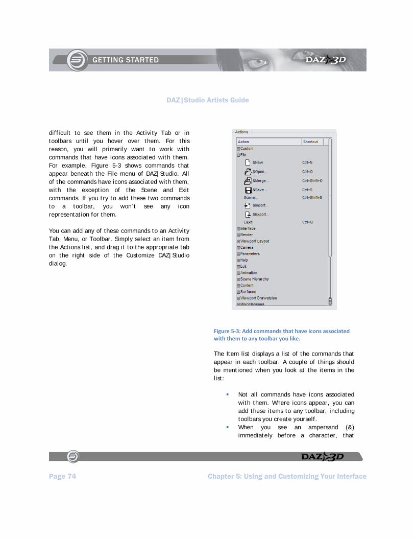
DAZ|Studio Artists Guide
Page 74 Chapter 5: Using and Customizing Your Interface
difficult to see them in the Activity Tab or in toolbars until you hover over them. For this reason, you will primarily want to work with commands that have icons associated with them. For example, Figure 5-3 shows commands that appear beneath the File menu of DAZ|Studio. All of the commands have icons associated with them, with the exception of the Scene and Exit commands. If you try to add these two commands to a toolbar, you won’t see any icon representation for them.
You can add any of these commands to an Activity Tab, Menu, or Toolbar. Simply select an item from the Actions list, and drag it to the appropriate tab on the right side of the Customize DAZ|Studio dialog.
Figure 5‐3: Add commands that have icons associated with them to any toolbar you like.
The Item list displays a list of the commands that appear in each toolbar. A couple of things should be mentioned when you look at the items in the list:
Not all commands have icons associated with them. Where icons appear, you can add these items to any toolbar, including toolbars you create yourself.
When you see an ampersand (&) immediately before a character, that

DAZ|Studio Artists Guide
Chapter 5: Using and Customizing Your Interface Page 75
means that you can use the key that follows to invoke the command when the menu is open. This is different from shortcuts, which do not need to have the menu open to use them. For example, you can use the shortcut Ctrl+Shift+O at any time to invoke the File > Merge command. However, when the File menu is open you can either click Merge or press the letter “m” to use the command. Menu hotkeys are always underlined in menus, as shown in Figure 5-4.
Figure 5‐4: Hotkeys are underlined in the command name. Shortcuts are shown in the right column when present.
The right portion of the Customize DAZ|Studio dialog is shown in Figure 5-5. It contains three sub-tabs, the purpose of which will be discussed in the sections that follow.
Use the Activities sub-tab to customize the icons and toolbars that appear in any Activity Tab, or to create your own Activity Tabs.
Use the Menus sub-tab to customize the commands that appear in each of the menus in DAZ|Studio, or to create your own custom sub-menus.
Use the Tool Bars sub-tab to customize the icons that appear in toolbars, or to create your own toolbars.
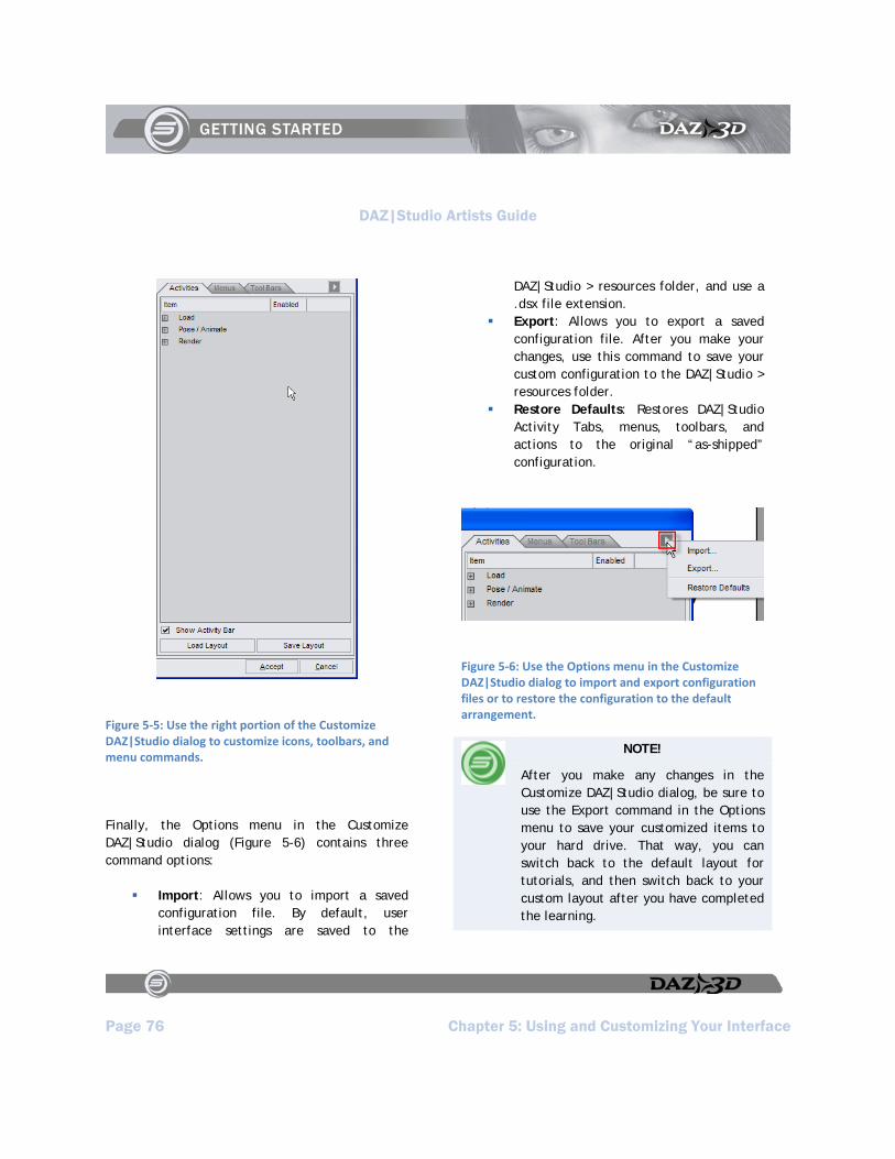
DAZ|Studio Artists Guide
Page 76 Chapter 5: Using and Customizing Your Interface
Figure 5‐5: Use the right portion of the Customize DAZ|Studio dialog to customize icons, toolbars, and menu commands.
Finally, the Options menu in the Customize DAZ|Studio dialog (Figure 5-6) contains three command options:
Import: Allows you to import a saved configuration file. By default, user interface settings are saved to the
DAZ|Studio > resources folder, and use a .dsx file extension.
Export: Allows you to export a saved configuration file. After you make your changes, use this command to save your custom configuration to the DAZ|Studio > resources folder.
Restore Defaults: Restores DAZ|Studio Activity Tabs, menus, toolbars, and actions to the original “as-shipped” configuration.
Figure 5‐6: Use the Options menu in the Customize DAZ|Studio dialog to import and export configuration files or to restore the configuration to the default arrangement.
NOTE!
After you make any changes in the Customize DAZ|Studio dialog, be sure to use the Export command in the Options menu to save your customized items to your hard drive. That way, you can switch back to the default layout for tutorials, and then switch back to your custom layout after you have completed the learning.
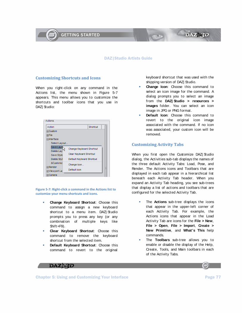
DAZ|Studio Artists Guide
Chapter 5: Using and Customizing Your Interface Page 77
Customizing Shortcuts and Icons
When you right-click on any command in the Actions list, the menu shown in Figure 5-7 appears. This menu allows you to customize the shortcuts and toolbar icons that you use in DAZ|Studio:
Figure 5‐7: Right‐click a command in the Actions list to customize your menu shortcuts and icons.
Change Keyboard Shortcut: Choose this command to assign a new keyboard shortcut to a menu item. DAZ|Studio prompts you to press any key (or any combination of multiple keys like Shift+F9).
Clear Keyboard Shortcut: Choose this command to remove the keyboard shortcut from the selected item.
Default Keyboard Shortcut: Choose this command to revert to the original
keyboard shortcut that was used with the shipping version of DAZ|Studio.
Change Icon: Choose this command to select an icon image for the command. A dialog prompts you to select an image from the DAZ|Studio > resources > images folder. You can select an icon image in JPG or PNG format.
Default Icon: Choose this command to revert to the original icon image associated with the command. If no icon was associated, your custom icon will be removed.
Customizing Activity Tabs
When you first open the Customize DAZ|Studio dialog, the Activities sub-tab displays the names of the three default Activity Tabs: Load, Pose, and Render. The Actions icons and Toolbars that are displayed in each tab appear in a hierarchical list beneath each Activity Tab header. When you expand an Activity Tab heading, you see sub-trees that display a list of actions and toolbars that are configured for the selected Activity Tab.
The Actions sub-tree displays the icons that appear in the upper-left corner of each Activity Tab. For example, the Actions icons that appear in the Load Activity Tab are icons for the File > New, File > Open, File > Import, Create > New Primitive, and What’s This help commands.
The Toolbars sub-tree allows you to enable or disable the display of the Help, Create, Tools, and Main toolbars in each of the Activity Tabs.
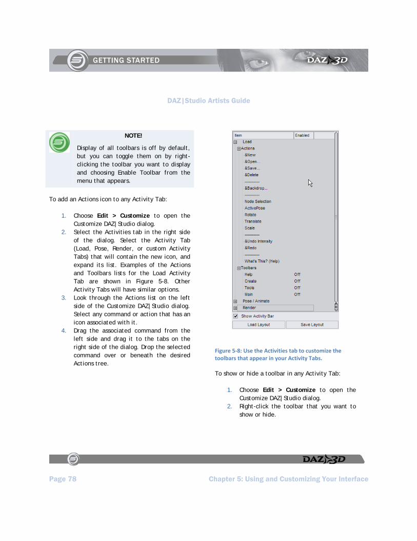
DAZ|Studio Artists Guide
Page 78 Chapter 5: Using and Customizing Your Interface
NOTE!
Display of all toolbars is off by default, but you can toggle them on by right-clicking the toolbar you want to display and choosing Enable Toolbar from the menu that appears.
To add an Actions icon to any Activity Tab:
1. Choose Edit > Customize to open the Customize DAZ|Studio dialog.
2. Select the Activities tab in the right side of the dialog. Select the Activity Tab (Load, Pose, Render, or custom Activity Tabs) that will contain the new icon, and expand its list. Examples of the Actions and Toolbars lists for the Load Activity Tab are shown in Figure 5-8. Other Activity Tabs will have similar options.
3. Look through the Actions list on the left side of the Customize DAZ|Studio dialog. Select any command or action that has an icon associated with it.
4. Drag the associated command from the left side and drag it to the tabs on the right side of the dialog. Drop the selected command over or beneath the desired Actions tree.
Figure 5‐8: Use the Activities tab to customize the toolbars that appear in your Activity Tabs.
To show or hide a toolbar in any Activity Tab:
1. Choose Edit > Customize to open the Customize DAZ|Studio dialog.
2. Right-click the toolbar that you want to show or hide.
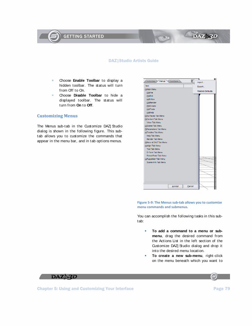
DAZ|Studio Artists Guide
Chapter 5: Using and Customizing Your Interface Page 79
Choose Enable Toolbar to display a hidden toolbar. The status will turn from Off to On.
Choose Disable Toolbar to hide a displayed toolbar. The status will turn from On to Off.
Customizing Menus
The Menus sub-tab in the Customize DAZ|Studio dialog is shown in the following figure. This sub-tab allows you to customize the commands that appear in the menu bar, and in tab options menus.
Figure 5‐9: The Menus sub‐tab allows you to customize menu commands and submenus.
You can accomplish the following tasks in this sub-tab:
To add a command to a menu or sub-menu, drag the desired command from the Actions List in the left section of the Customize DAZ|Studio dialog and drop it into the desired menu location.
To create a new sub-menu, right-click on the menu beneath which you want to
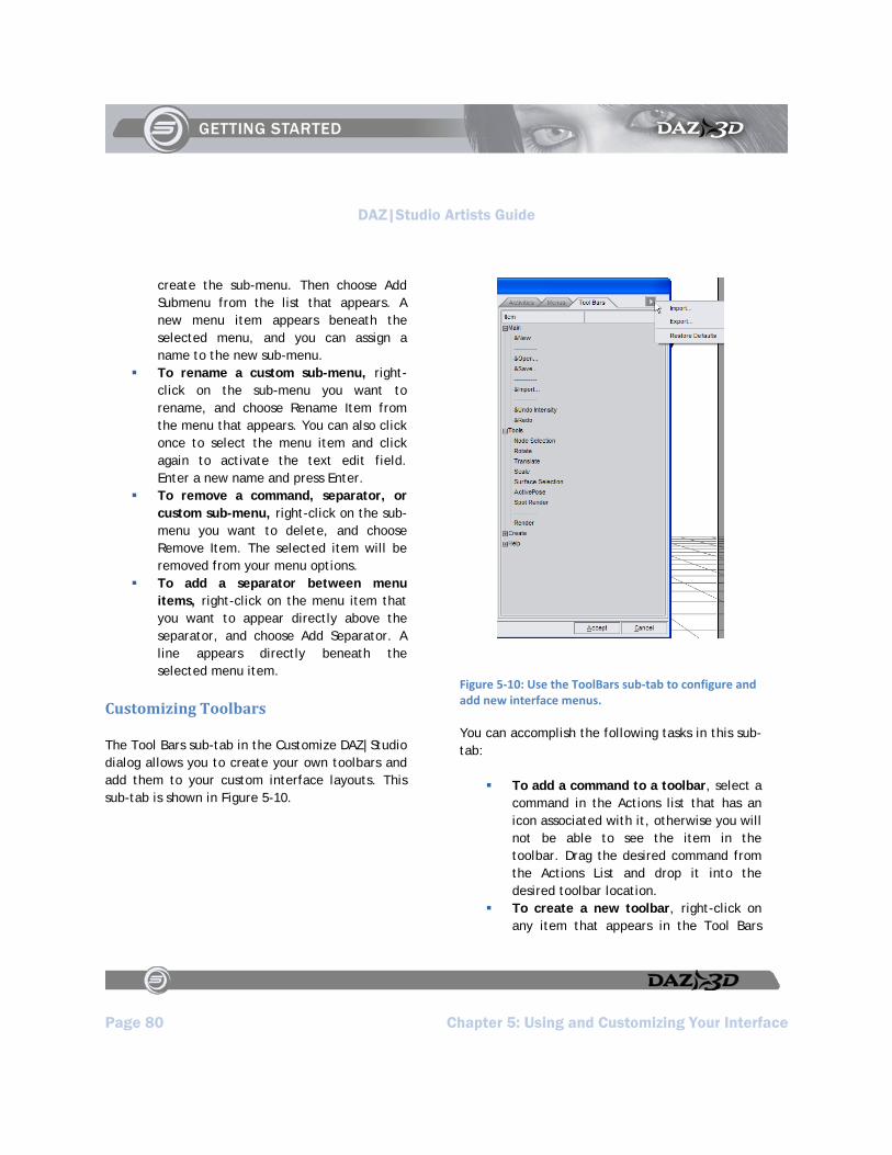
DAZ|Studio Artists Guide
Page 80 Chapter 5: Using and Customizing Your Interface
create the sub-menu. Then choose Add Submenu from the list that appears. A new menu item appears beneath the selected menu, and you can assign a name to the new sub-menu.
To rename a custom sub-menu, right-click on the sub-menu you want to rename, and choose Rename Item from the menu that appears. You can also click once to select the menu item and click again to activate the text edit field. Enter a new name and press Enter.
To remove a command, separator, or custom sub-menu, right-click on the sub-menu you want to delete, and choose Remove Item. The selected item will be removed from your menu options.
To add a separator between menu items, right-click on the menu item that you want to appear directly above the separator, and choose Add Separator. A line appears directly beneath the selected menu item.
Customizing Toolbars
The Tool Bars sub-tab in the Customize DAZ|Studio dialog allows you to create your own toolbars and add them to your custom interface layouts. This sub-tab is shown in Figure 5-10.
Figure 5‐10: Use the ToolBars sub‐tab to configure and add new interface menus.
You can accomplish the following tasks in this sub-tab:
To add a command to a toolbar, select a command in the Actions list that has an icon associated with it, otherwise you will not be able to see the item in the toolbar. Drag the desired command from the Actions List and drop it into the desired toolbar location.
To create a new toolbar, right-click on any item that appears in the Tool Bars

DAZ|Studio Artists Guide
Chapter 5: Using and Customizing Your Interface Page 81
tab, and choose Add Toolbar. A new toolbar item appears and you can assign a name to the new toolbar.
To rename a toolbar, right-click on the toolbar you want to rename, and choose Rename Item from the menu that appears. You can also click once to select the toolbar item and click again to activate the text edit field. Enter a new name and press Enter.
To remove a command, separator, or custom toolbar, right-click on the item you want to delete, and choose Remove Item. The selected item will be removed from your toolbar options.
To add a separator between items in the toolbar, right-click on the toolbar command that you want to appear directly above the separator, and choose Add Separator. A line appears directly beneath the selected toolbar item.
Customizing Your Layout
In addition to creating your own Activity Tabs, menus, shortcuts, and toolbars, DAZ|Studio also gives you a degree of control over the interface layout, allowing you to customize it to your specific uses and needs. You can customize the interface by moving and resizing panes, moving tabs, and using multiple monitors.
Using Multiple Monitors
DAZ|Studio supports multiple monitors. When you make changes to your interface layout, you can click and drag your pane(s) or other elements to
any available monitor. This allows you to create a larger area for your viewport.
Customizing Panes
Figure 5-11 displays the various components that you use in conjunction with customizing your panes and how you view them when they are docked. The controls that are common to most panes are as follows:
Pane Edge: The Pane Edge appears along the side of the pane, at the side that is closest to the Viewport. You can reposition the edge to size each pane to your liking.
Pane Toggle: When appropriate, the Pane Toggle allows you to expand or collapse the contents of the pane. The pane toggle is represented by two solid arrows facing in opposite directions. The direction of the arrows indicates the direction in which the pane contents will collapse or expand.
Pane Grip: The Pane Grip area appears immediately to the right and left of the Pane Toggle. Drag the pane from this area to move the pane to a new location.
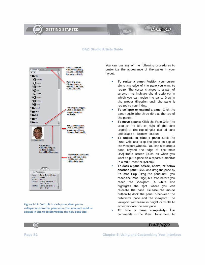
DAZ|Studio Artists Guide
Page 82 Chapter 5: Using and Customizing Your Interface
Figure 5‐11: Controls in each pane allow you to collapse or resize the pane area. The viewport window adjusts in size to accommodate the new pane size.
You can use any of the following procedures to customize the appearance of the panes in your layout:
To resize a pane: Position your cursor along any edge of the pane you want to resize. The cursor changes to a pair of arrows that indicate the direction(s) in which you can resize the pane. Drag in the proper direction until the pane is resized to your liking.
To collapse or expand a pane: Click the pane toggle (the three dots at the top of the pane).
To move a pane: Click the Pane Grip (the area to the left or right of the pane toggle) at the top of your desired pane and drag it to its new location.
To undock or float a pane: Click the Pane Grip and drop the pane on top of the viewport window. You can also drop a pane beyond the edge of the main DAZ|Studio screen (such as when you want to put a pane on a separate monitor in a multi-monitor system).
To dock a pane beside, above, or below another pane: Click and drag the pane by its Pane Grip. Drag the pane until you reach the Pane Edge, but stop before you reach the Viewport. A white line highlights the spot where you can relocate the pane. Release the mouse button to dock the pane in-between the outermost pane and the viewport. The viewport will resize in height or width to accommodate the new pane.
To hide a pane completely: Use commands in the View: Tabs menu to
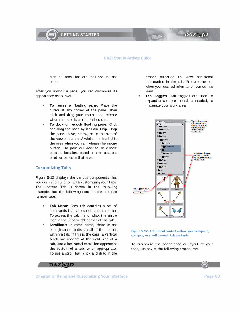
DAZ|Studio Artists Guide
Chapter 5: Using and Customizing Your Interface Page 83
hide all tabs that are included in that pane.
After you undock a pane, you can customize its appearance as follows:
To resize a floating pane: Place the cursor at any corner of the pane. Then click and drag your mouse and release when the pane is at the desired size.
To dock or redock floating pane: Click and drag the pane by its Pane Grip. Drop the pane above, below, or to the side of the viewport area. A white line highlights the area when you can release the mouse button. The pane will dock to the closest possible location, based on the locations of other panes in that area.
Customizing Tabs
Figure 5-12 displays the various components that you use in conjunction with customizing your tabs. The Content Tab is shown in the following example, but the following controls are common to most tabs.
Tab Menu: Each tab contains a set of commands that are specific to that tab. To access the tab menu, click the arrow icon in the upper-right corner of the tab.
Scrollbars: In some cases, there is not enough space to display all of the options within a tab. If this is the case, a vertical scroll bar appears at the right side of a tab, and a horizontal scroll bar appears at the bottom of a tab, when appropriate. To use a scroll bar, click and drag in the
proper direction to view additional information in the tab. Release the bar when your desired information comes into view.
Tab Toggles: Tab toggles are used to expand or collapse the tab as needed, to maximize your work area.
Figure 5‐12: Additional controls allow you to expand, collapse, or scroll through tab contents.
To customize the appearance or layout of your tabs, use any of the following procedures:
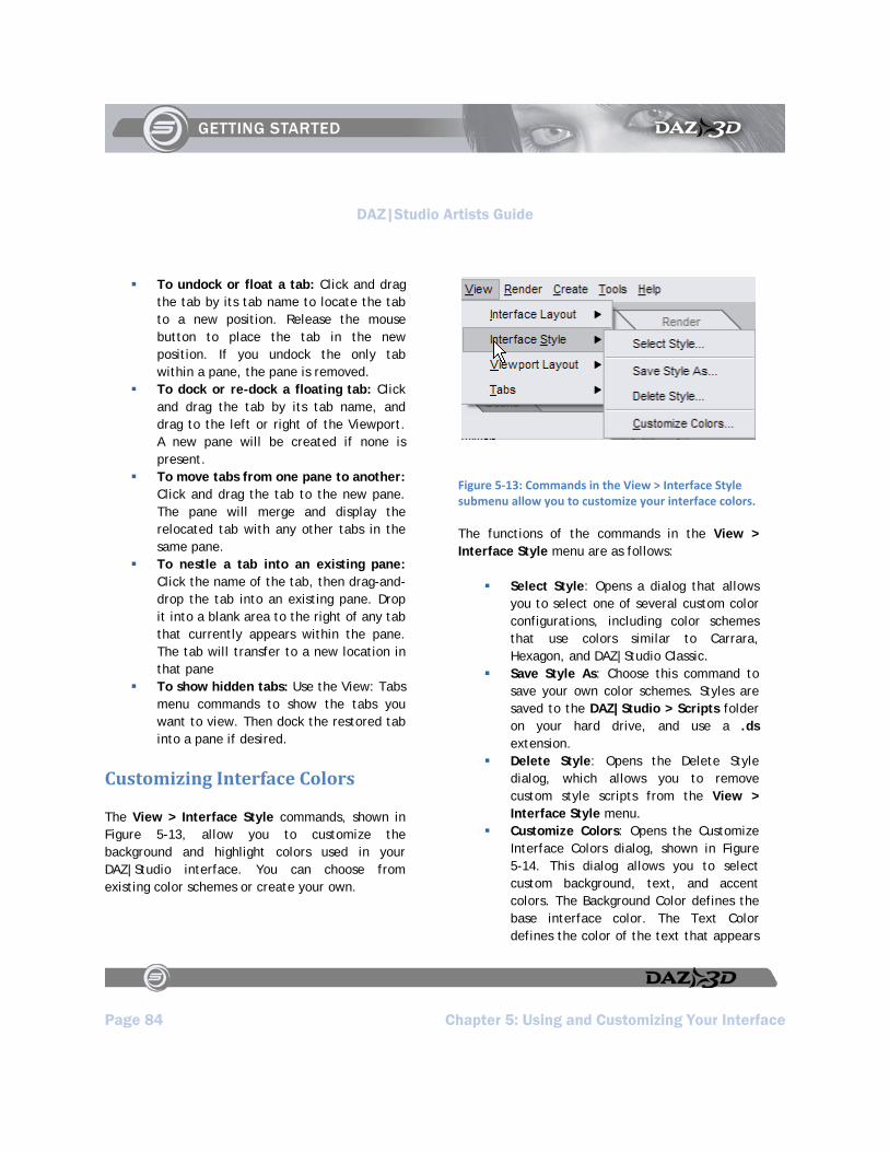
DAZ|Studio Artists Guide
Page 84 Chapter 5: Using and Customizing Your Interface
To undock or float a tab: Click and drag the tab by its tab name to locate the tab to a new position. Release the mouse button to place the tab in the new position. If you undock the only tab within a pane, the pane is removed.
To dock or re-dock a floating tab: Click and drag the tab by its tab name, and drag to the left or right of the Viewport. A new pane will be created if none is present.
To move tabs from one pane to another: Click and drag the tab to the new pane. The pane will merge and display the relocated tab with any other tabs in the same pane.
To nestle a tab into an existing pane: Click the name of the tab, then drag-and-drop the tab into an existing pane. Drop it into a blank area to the right of any tab that currently appears within the pane. The tab will transfer to a new location in that pane
To show hidden tabs: Use the View: Tabs menu commands to show the tabs you want to view. Then dock the restored tab into a pane if desired.
Customizing Interface Colors
The View > Interface Style commands, shown in Figure 5-13, allow you to customize the background and highlight colors used in your DAZ|Studio interface. You can choose from existing color schemes or create your own.
Figure 5‐13: Commands in the View > Interface Style submenu allow you to customize your interface colors.
The functions of the commands in the View > Interface Style menu are as follows:
Select Style: Opens a dialog that allows you to select one of several custom color configurations, including color schemes that use colors similar to Carrara, Hexagon, and DAZ|Studio Classic.
Save Style As: Choose this command to save your own color schemes. Styles are saved to the DAZ|Studio > Scripts folder on your hard drive, and use a .ds extension.
Delete Style: Opens the Delete Style dialog, which allows you to remove custom style scripts from the View > Interface Style menu.
Customize Colors: Opens the Customize Interface Colors dialog, shown in Figure 5-14. This dialog allows you to select custom background, text, and accent colors. The Background Color defines the base interface color. The Text Color defines the color of the text that appears

DAZ|Studio Artists Guide
Chapter 5: Using and Customizing Your Interface Page 85
in the menus, tabs, and dialog boxes. The Accent Color defines a secondary color for items like borders and inactive tabs. After you create your custom colors, click Accept. Then use the Save Style As command to save the configuration, and the Add Existing Styles command to add them to the View > Interface Style menu.
Figure 5‐14: Assign custom colors to your DAZ|Studio interface with the Customize Interface Colors dialog.
Setting Interface Preferences
The Preferences dialog box contains a tab that allows you to customize the background and text colors used in your interface, along with several other options. To set the Interface Preferences, choose Edit > Preferences to open the Preferences dialog (Figure 5-15). Click the Interface tab to view the following options:
Figure 5‐15: The Interface tab in the Preferences dialog allows you to choose the default appearance of your interface.
The options are as follows:
Show Tool Tips: Check the Show Tool Tips checkbox to display information about a tool when you hover over it with your mouse cursor. Clear this checkbox to disable this feature.
Activity Image: Allows you to customize the image that appears in the right portion of the interface. By default, a grayscale image of Victoria 4 appears. You can also choose None, a Dragon, Trees, or Cycle (which cycles through all available images).
Open GL: If your card cannot support OpenGL, a notice informs you as such you’re your card supports OpenGL, the following options appear:
Manipulation Draw Style: The Manipulation Draw Style option

DAZ|Studio Artists Guide
Page 86 Chapter 5: Using and Customizing Your Interface
allows you to conserve computing resources by displaying scene elements in reduced detail while you are manipulating (posing or moving) an object, camera, or light. There are three options: Choose Off to display the objects in your scene as they normally appear (with full geometry shape and textures) while you manipulate them. This option consumes the most computer resources. Choose Wireframe Box to display your objects in wireframe mode while you manipulate them. This option consumes the least amount of computer resources. Choose Smooth-Shaded Box to display your objects as smooth boxes while you manipulate them.
Hardware AntiAliasing: Click the option box to toggle this option Off or On. When On, this option transfers all the edge smoothing actions to the video card instead of to your CPU. You may want to turn this option Off if your video card supports OpenGL acceleration but is below the recommended requirements.
OpenGL Texture Quality: This option controls the quality of the textures in your Viewport. Drag the slider from left to right, or use the right and left arrow keys, to use the setting that is best for your system resources. Slider options, from left to right, are Best Performance, Good Performance, High Quality, and Best Quality.
About Current Hardware: Click this button to view a list of features that are supported by your OpenGL-compliant video card. The list includes the OpenGL version supported by your card, and displays its manufacturer’s name and model number. A list of supported features then follow, including limitations on the number of lights, texture units, and maximum texture size that the card can support.
Restore Factory Defaults: Click this button to remove all of your custom settings and return to the default settings furnished with your DAZ|Studio installation.
After you complete your Interface Preferences settings, use one of the three buttons at the bottom of the dialog:
Click Apply to set the settings for the current preference tab; the Preferences dialog remains open so that you can set other preferences.
Click Accept to exit the dialog immediately.
Click Cancel to exit the Preferences dialog and discard any unsaved changes.
Saving Your Custom Interface Layout
After you rearrange your interface, it’s a good idea to save your custom layout. You might also find that it is convenient to create several different interface layouts. For example, you
DAZ|Studio Artists Guide
Chapter 5: Using and Customizing Your Interface Page 87
might create a layout for when you are putting your scenes together, and then prefer a different layout when you are posing your figures.
To save a custom layout, choose the View > Interface Layout > Save Layout As command. The Save Layout As dialog prompts you to assign a name to your new layout. By default, the layout is saved into the Studio > Scripts > Layouts folder as a DAZ|Script.
Loading Custom Interface Layouts
Any time you want to switch to an interface layout that is saved onto your hard drive, choose View > Interface Layout > Select Layout, and select a layout from the dialog that appears. Click Apply or Accept to use the layout you select.
For reference, the custom layouts that you create are saved into the Studio > Scripts > Layouts folder by default.

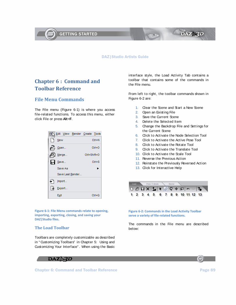
DAZ|Studio Artists Guide
Chapter 6: Command and Toolbar Reference Page 89
Chapter 6 : Command and Toolbar Reference
File Menu Commands
The File menu (Figure 6-1) is where you access file-related functions. To access this menu, either click File or press Alt+F.
Figure 6‐1: File Menu commands relate to opening, importing, exporting, closing, and saving your DAZ|Studio files.
The Load Toolbar
Toolbars are completely customizable as described in “Customizing Toolbars” in Chapter 5: Using and Customizing Your Interface”. When using the Basic
interface style, the Load Activity Tab contains a toolbar that contains some of the commands in the File menu.
From left to right, the toolbar commands shown in Figure 6-2 are:
1. Clear the Scene and Start a New Scene 2. Open an Existing File 3. Save the Current Scene 4. Delete the Selected Item 5. Change the Backdrop File and Settings for
the Current Scene 6. Click to Activate the Node Selection Tool 7. Click to Activate the Active Pose Tool 8. Click to Activate the Rotate Tool 9. Click to Activate the Translate Tool 10. Click to Activate the Scale Tool 11. Reverse the Previous Action 12. Reinstate the Previously Reversed Action 13. Click for Interactive Help
Figure 6‐2: Commands in the Load Activity Toolbar serve a variety of file‐related functions.
The commands in the File menu are described below:
DAZ|Studio Artists Guide
Page 90 Chapter 6: Command and Toolbar Reference
New
To close your current scene file and start a new blank scene, choose one of the following options:
Choose File > New Click the Clear the Scene icon in the
Load Toolbar Use the keyboard shortcut Ctrl+N
You will be prompted to save any unsaved changes before the new scene appears. If you do not save these changes, you will lose them. This action also clears and resets the Undo/Redo stack.
CAUTION!
If you open a new scene or otherwise close the old one without saving it, you will lose all unsaved work within a scene.
Open
To open a DAZ|Studio scene file that you previously saved, use one of the following methods:
Choose File > Open Click the Open an Existing File icon in
the Load Toolbar Use the shortcut Ctrl+O
A standard Open File dialog box appears. Navigate to the folder that contains your desired file, and select the file to open it. You will be prompted to save any work on the current scene before the
new file opens. This action also clears and resets the Undo/Redo stack.
Merge
The Merge command allows you to merge a previously-saved scene into your current scene. Use one of the following methods:
Choose File > Merge Use the keyboard shortcut Ctrl+Shift+O
Save
The Save command allows you to save your scene for the first time, or to overwrite a previous version of your current file with your latest changes. If you have not yet saved your scene, the Save File As dialog prompts you to choose a location and filename.
To save your current scene, use one of the following methods:
Choose File > Save Use the keyboard shortcut Ctrl+S
Save As
The Save As command allows you to save several different types of files:
Choose File > Save As > Scene or press Ctrl+Shift+S to save all or part of your current scene to a different filename. You can save multiple versions of the same scene so that you can easily return
DAZ|Studio Artists Guide
Chapter 6: Command and Toolbar Reference Page 91
to a previous version. A standard Save As dialog allows you to select your desired folder and filename. Scenes are saved with a .daz extension. When you save a Scene, it includes all information in your current scene. You can also use one of the other Save As options to save specific types of files to your content folder.
Choose File > Save As > D-Form Preset to save deformers to the folder of your choice.
Choose File > Save As > Puppeteer Preset to save custom Puppeteer poses to the folder of your choice.
Choose File > Save As > Pose Preset to save the current frame as a still pose, or all frames as an animated pose.
Choose File > Save As > Shader Preset to save the currently selected shader. The preset can include all surface properties or advanced surface properties.
Choose File > Save As > Materials Preset to save one or all of the materials in the current object.
Choose File > Save As > Light(s) Preset to save all lights or selected lights in your scene. You can save the lights as they appear in the current frame, or save a preset that animates your lighting.
Choose File > Save As > Camera(s) Preset to save all cameras or selected cameras in your scene. You can save the cameras as they appear in the current frame, or save a preset that animates the cameras
Save Last Render
Choose File > Save Last Render or press Ctrl+Shift+R to save your last rendered image as a file on your hard drive. A standard Browse dialog allows you to select a filename and folder for your saved image. This command will not be enabled until after you create a render in your current session.
Import
DAZ|Studio allows you to import content that has been saved in several different formats. Choose File > Import or use the Import an Existing File button on the Main Toolbar. A Browse dialog appears for you to locate and select your desired content.
The currently supported import formats are:
Biovision animation files (.bvh) Poser 4(R) or earlier versions:
.pz3 (.pzz for compressed version) - scene files
.pz2 (.p2z for compressed version) - Pose Library files
.cr2 (.crz for compressed version) - Character/Figure Library files
.cm2 (.cmz for compressed version) - Camera Library files
.lt2 (.ltz for compressed version) - Light Library files
.hd2 (.hdz for compressed version) - Hand Library files

DAZ|Studio Artists Guide
Page 92 Chapter 6: Command and Toolbar Reference
.fc2 (.fcz for compressed version) - Face/Expression Library files
.hr2 (.hrz for compressed version) - Hair Library files
Wavefront Object (*.obj) and Compressed Object (.obz).
Export
Choose File > Export to save content to different formats. The Save As dialog allows you to select your desired folder and filename. The currently supported export formats are:
BioVision (.bvh) animation files COLLADA (.dae) files Wavefront Object (*.obj) - For Bryce or
other 3D programs that import 3D geometry in this format.
Universal 3D (*.u3d) - A 3D format that allows you to import your DAZ Studio 3D content into Photoshop CS3 Extended
NOTE!
Additional plug-ins are available for DAZ|Studio to provide additional export options.
Exit
To exit the DAZ|Studio application, use one of the following options. You will be prompted to save any unsaved changes.
Choose File > Exit
Press Alt+F4 (Windows) or Ctrl+Q (any platform).
CAUTION!
If you exit DAZ|Studio without saving your current scene, you will lose all unsaved changes with no prompt to save them. This also occurs if you click on the “X” icon in the upper-right corner of the DAZ|Studio window title bar while in Windows.
CAUTION!
Unlike most applications in OSX, Clicking the “X” icon in the upper-left corner of the DAZ|Studio window title bar WILL SHUT DOWN DAZ|Studio COMPLETELY, and you will lose all unsaved changes with no prompt to save them.
Edit Menu Commands
The Edit menu (Figure 6-3) allows you to perform standard editing functions and to set global DAZ|Studio preferences. To access this menu, either click Edit or press Alt+E.
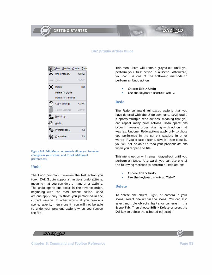
DAZ|Studio Artists Guide
Chapter 6: Command and Toolbar Reference Page 93
Figure 6‐3: Edit Menu commands allow you to make changes in your scene, and to set additional preferences.
Undo
The Undo command reverses the last action you took. DAZ|Studio supports multiple undo actions, meaning that you can delete many prior actions. The undo operations occur in the reverse order, beginning with the most recent action. Undo actions apply only to those you performed in the current session. In other words, if you create a scene, save it, then close it, you will not be able to undo your previous actions when you reopen the file.
This menu item will remain grayed-out until you perform your first action in a scene. Afterward, you can use one of the following methods to perform an Undo action:
Choose Edit > Undo Use the keyboard shortcut Ctrl+Z
Redo
The Redo command reinstates actions that you have deleted with the Undo command. DAZ|Studio supports multiple redo actions, meaning that you can repeat many prior actions. Redo operations occur in reverse order, starting with action that was last Undone. Redo actions apply only to those you performed in the current session. In other words, if you create a scene, save it, then close it, you will not be able to redo your previous actions when you reopen the file.
This menu option will remain grayed-out until you perform an Undo. Afterward, you can use one of the following methods to perform a Redo action:
Choose Edit > Redo Use the keyboard shortcut Ctrl+Y
Delete
To delete one object, light, or camera in your scene, select one within the scene. You can also select multiple objects, lights, or cameras in the Scene Tab. Then choose Edit > Delete or press the Del key to delete the selected object(s).
DAZ|Studio Artists Guide
Page 94 Chapter 6: Command and Toolbar Reference
Delete All Lights
If your scene contains one or more lights, choose Edit > Delete All Lights to delete all of the lights in your scene.
Delete All Cameras
If your scene contains one or more cameras, choose Edit > Delete All Cameras to delete all of the cameras in your scene.
Copy Settings
Choose Edit > Copy Settings or use the keyboard shortcut Ctrl+C to copy settings from one object to another. For example, you can select the figure’s right thigh and copy it to the clipboard.
Paste Settings
Choose Edit > Paste Settings or use the keyboard shortcut Ctrl+V to paste settings from the clipboard into another object. For example, if you copied pose settings from a figure’s right thigh into the clipboard, you could paste them to the left thigh.
Backdrop
To insert a background image into the scene, choose Edit > Backdrop. The Backdrop Options dialog prompts you to choose an image. You then have the option to rotate the background left 90 degrees, right 90 degrees, or 180 degrees. You can also flip the image horizontally or vertically.
Audio
Choose Edit > Audio to add an audio file as a background for an animation. The Audio Options dialog prompts you to select a .WAV file. You can play the audio file to preview the sound, and specify the frame number in your animation where the audio file should start to play.
Preferences
Selecting Edit > Preferences opens the Preferences dialog, which contains four tabs: General, Directories, Interface, and Scene. Refer to Chapter 5, “Using and Customizing Your Interface” and Appendix A, “Setting Preferences” for more information on these settings.
Customize
Choose Edit > Customize to open the Customize DAZ|Studio dialog, which allows you to customize menus, buttons, and toolbars to suit your own preferences.
View Menu Commands
The View menu (Figure 6-4) allows you to display and hide various items on your screen, configure the viewport layout, and show or hide various tabs. You can also save custom layouts.
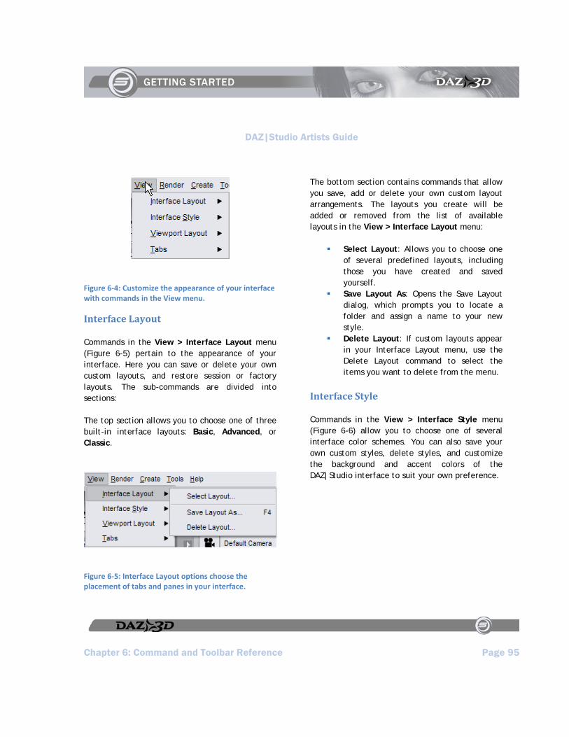
DAZ|Studio Artists Guide
Chapter 6: Command and Toolbar Reference Page 95
Figure 6‐4: Customize the appearance of your interface with commands in the View menu.
Interface Layout
Commands in the View > Interface Layout menu (Figure 6-5) pertain to the appearance of your interface. Here you can save or delete your own custom layouts, and restore session or factory layouts. The sub-commands are divided into sections:
The top section allows you to choose one of three built-in interface layouts: Basic, Advanced, or Classic.
Figure 6‐5: Interface Layout options choose the placement of tabs and panes in your interface.
The bottom section contains commands that allow you save, add or delete your own custom layout arrangements. The layouts you create will be added or removed from the list of available layouts in the View > Interface Layout menu:
Select Layout: Allows you to choose one of several predefined layouts, including those you have created and saved yourself.
Save Layout As: Opens the Save Layout dialog, which prompts you to locate a folder and assign a name to your new style.
Delete Layout: If custom layouts appear in your Interface Layout menu, use the Delete Layout command to select the items you want to delete from the menu.
Interface Style
Commands in the View > Interface Style menu (Figure 6-6) allow you to choose one of several interface color schemes. You can also save your own custom styles, delete styles, and customize the background and accent colors of the DAZ|Studio interface to suit your own preference.

DAZ|Studio Artists Guide
Page 96 Chapter 6: Command and Toolbar Reference
Figure 6‐6: Choose or create custom interface colors with the Interface Style commands.
Select Style: Choose this command to select the interface color scheme that you want to use.
Save Style As: After you create your own interface style, choose View > Interface Style > Save Style As. The Save Style dialog prompts you to locate a folder and assign a name to the new style. By default, DAZ|Studio saves the new styles to the DAZ Studio > scripts folder.
Delete Style: If custom styles appear in your Interface Style menu, the Delete Styles command allows you to select the items you want to delete from the menu.
Customize Colors: Opens the Customize Interface Colors dialog, which allows you to choose Background, Text, and Accent colors for your interface.
Viewport Layout
Commands in the View > Viewport Layout menu (Figure 6-7) allow you to view your scene using up to four viewports at once. You will see a list of
available viewport layout options, shown in the following figure. Click your desired selection and the viewport layout will immediately change accordingly.
Figure 6‐7: Display one to four different viewports in your viewport with commands in the Viewport Layout menu.
Tabs
The View > Tabs submenu (Figure 6-8) allows you to customize the DAZ|Studio interface by toggling various tabs on and off. If a tab is hidden, click the tab name to show it, and vice-versa. A checkmark appears next to each visible tab.
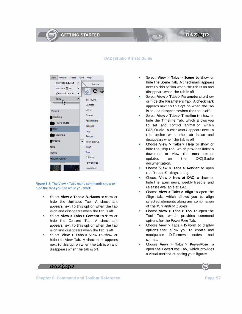
DAZ|Studio Artists Guide
Chapter 6: Command and Toolbar Reference Page 97
Figure 6‐8: The View > Tabs menu commands show or hide the tabs you see while you work.
Select View > Tabs > Surfaces to show or hide the Surfaces Tab. A checkmark appears next to this option when the tab is on and disappears when the tab is off.
Select View > Tabs > Content to show or hide the Content Tab. A checkmark appears next to this option when the tab is on and disappears when the tab is off.
Select View > Tabs > View to show or hide the View Tab. A checkmark appears next to this option when the tab is on and disappears when the tab is off.
Select View > Tabs > Scene to show or hide the Scene Tab. A checkmark appears next to this option when the tab is on and disappears when the tab is off.
Select View > Tabs > Parameters to show or hide the Parameters Tab. A checkmark appears next to this option when the tab is on and disappears when the tab is off.
Select View > Tabs > Timeline to show or hide the Timeline Tab, which allows you to set and control animation within DAZ|Studio. A checkmark appears next to this option when the tab is on and disappears when the tab is off.
Choose View > Tabs > Help to show or hide the Help tab, which provides links to download or view the most recent updates on the DAZ|Studio documentation.
Choose View > Tabs > Render to open the Render Settings dialog.
Choose View > New at DAZ to show or hide the latest news, weekly freebie, and releases available at DAZ.
Choose View > Tabs > Align to open the Align tab, which allows you to align selected elements along any combination of the X, Y and/or Z Axes.
Choose View > Tabs > Tool to open the Tool Tab, which provides command options for the PowerPose Tab.
Choose View > Tabs > D-Form to display options that allow you to create and manipulate D-Formers, nodes, and splines.
Choose View > Tabs > PowerPose to open the PowerPose Tab, which provides a visual method of posing your figures.
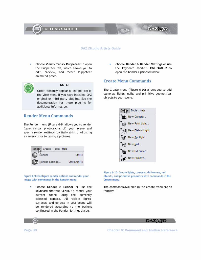
DAZ|Studio Artists Guide
Page 98 Chapter 6: Command and Toolbar Reference
Choose View > Tabs > Puppeteer to open the Puppeteer tab, which allows you to edit, preview, and record Puppeteer animated poses.
NOTE!
Other tabs may appear at the bottom of the View menu if you have installed DAZ original or third party plug-ins. See the documentation for these plug-ins for additional information.
Render Menu Commands
The Render menu (Figure 6-9) allows you to render (take virtual photographs of) your scene and specify render settings (partially akin to adjusting a camera prior to taking a picture).
Figure 6‐9: Configure render options and render your image with commands in the Render menu.
Choose Render > Render or use the keyboard shortcut Ctrl+R to render your current scene using the currently selected camera. All visible lights, surfaces, and objects in your scene will be rendered according to the options configured in the Render Settings dialog.
Choose Render > Render Settings or use the keyboard shortcut Ctrl+Shift+R to open the Render Options window.
Create Menu Commands
The Create menu (Figure 6-10) allows you to add cameras, lights, nulls, and primitive geometrical objects to your scene.
Figure 6‐10: Create lights, cameras, deformers, null objects, and primitive geometry with commands in the Create menu.
The commands available in the Create Menu are as follows:

DAZ|Studio Artists Guide
Chapter 6: Command and Toolbar Reference Page 99
New Camera
To create a new camera in your scene, choose Create > New Camera. This behaves just like a film camera you may have in real life.
New Point Light
Choose Create > New Point Light to add a new local omni-directional Point Light that is similar to the light given off by an incandescent light bulb. You can only adjust the location, intensity, color, and enable or disable shadow casting.
New Distant Light
Choose Create > New Distant Light to add a Distant Light. A Distant Light is a directional light that covers an entire scene, but has no real source position. The closest real-world example would be sunlight. You can adjust the direction in which the light aims, its intensity and color, and enable or disable shadow casting.
New Spotlight
Choose Create > New Spotlight to add a new Spotlight. A Spotlight is a directional light that is cone-shaped (like a flashlight), and which has an adjustable area.
New Null
Choose Create > New Null to add a null object to your scene. Nulls are useful for grouping objects/items by parenting those items to the null object. They are also useful for “point at” targets;
for instance, using persistent point at on the eyes, and then dragging the null around and having the eyes follow. They can also be used to mark a position in space for later reference.
New DFormer
Choose Create > New D-Former to add a new deformer to your scene. Deformers help you create morphs that change the shape of an object.
New Primitive
Choose Create > New Primitive to add a primitive geometry object to your scene. The Create New Primitive dialog allows you to choose one of six different geometrical shapes: Cube, Cylinder, Cone, Sphere, Torus, or Plane. Additional options allow you to specify the size of the object in meters, centimeters, yards, feet, or inches. You can also set the number of divisions in the object, with higher division numbers creating more polygons in the object.
Tools Menu Commands
The Tools menu (Figure 6-11) commands allow you to choose one of several different tools to manipulate objects and render the contents of your scene.

DAZ|Studio Artists Guide
Page 100 Chapter 6: Command and Toolbar Reference
Figure 6‐11: Use commands in the Tools menu to activate the DAZ|Studio tools.
NOTE!
Some of the Tools Menu commands are available in the toolbars that you find in the Load, Pose/Animate, and Render Activity Tabs (in the Basic Layout.
TIP!
The Rotate, Translate, and Scale Manipulators are great for getting poses, objects, etc., into their rough positions. For fine tuning, you will probably want to use the Parameters tab since it gives you more precise control.
The Tools menu commands serve the following functions:
Node Selection
To select any item in your scene, choose Tools > Node Selection or click the Node Selection Tool icon in the Pose toolbar. After you select an item you can view its properties in the Parameters window to make adjustments. You can also delete any selected item.
Rotate
To rotate items in your scene, choose Tools > Rotate or click the Rotate Tool icon in the Pose toolbar. In most cases, you cannot rotate body parts; however, because the hip is usually the root part of a figure you can rotate the entire body of a poseable figure by selecting the hip. The Rotate manipulator displays the rotation axes in three colors: Red rotates the object about the X axis. Green rotates the object about the Y axis. Blue rotates the object about the Z axis. Click and drag the circle that corresponds to the axis you want to rotate.
Translate
To move items in your scene, choose Tools > Translate or click the Translate Tool icon in the Pose toolbar. In most cases you cannot translate body parts; however, because the hip is usually the root part of a figure you can translate the entire body of a poseable figure by selecting the hip. The Translation manipulator displays three arrows pointing in the direction of each axis. The Red arrow translates the object in the X axis. The Green arrow translates the object along the Y

DAZ|Studio Artists Guide
Chapter 6: Command and Toolbar Reference Page 101
axis. The Blue arrow translates the object along the Z axis.
Scale
To scale items in your scene, choose Tools > Scale. If you select a body part (or bone) in a poseable figure, the scale function applies only to the geometry associated with that body part, and moves all children of that body part accordingly. For example, when you stretch the forearm, the hand and fingers at the end of the forearm move accordingly. To scale an entire figure, select it in the Scene Tab, then use the Parameters pane to perform the scaling. If you select a prop or other object with no body parts (such as a light), you will scale the entire object.
The Scaling manipulator displays each axis with a box on each end. To use the manipulator, click and drag the line corresponding to your desired axis, with Red being the X axis, Green being the Y axis, and Blue being the Z axis.
Surface Selection
Choose Tools > Surface Selection to select one or more surfaces to modify in the Surfaces Tab. Right-click on a surface, and you can select an individual surface for manipulation, select all surfaces with that selection’s Diffuse Color, select all surfaces that use the same Texture Map, or simply clear a previous surface selection. The affected surfaces will show in a white cross-hatched pattern as shown above.
PowerPose
Choose Tools > PowerPose or click the Active Pose Tool icon in an applicable toolbar to select and use the PowerPose tool.
Spot Render
Choose Tools > Spot Render to render a small portion of your scene for test purposes. To use this feature, click the button, then draw a rectangle in any viewport, around the area you want to render.
Help Menu Commands
The Help menu () is where you access DAZ|Studio documentation and information about your installation. To access this menu, either click Help or press Alt+H.
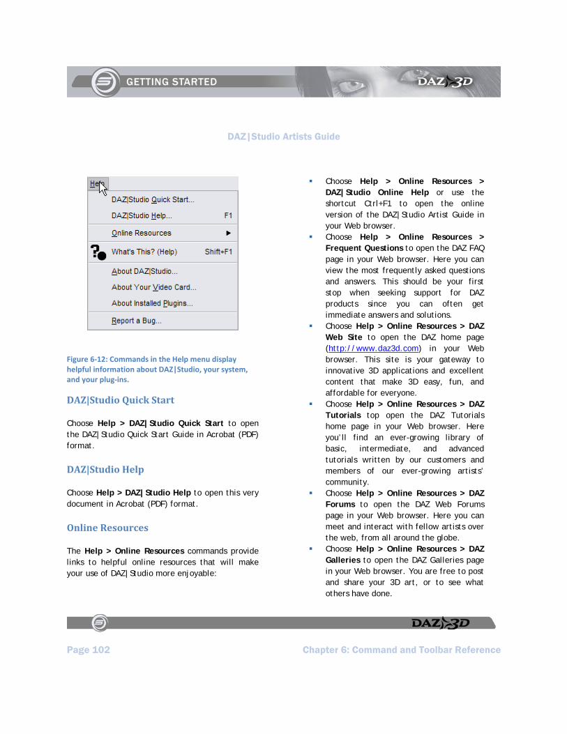
DAZ|Studio Artists Guide
Page 102 Chapter 6: Command and Toolbar Reference
Figure 6‐12: Commands in the Help menu display helpful information about DAZ|Studio, your system, and your plug‐ins.
DAZ|Studio Quick Start
Choose Help > DAZ|Studio Quick Start to open the DAZ|Studio Quick Start Guide in Acrobat (PDF) format.
DAZ|Studio Help
Choose Help > DAZ|Studio Help to open this very document in Acrobat (PDF) format.
Online Resources
The Help > Online Resources commands provide links to helpful online resources that will make your use of DAZ|Studio more enjoyable:
Choose Help > Online Resources > DAZ|Studio Online Help or use the shortcut Ctrl+F1 to open the online version of the DAZ|Studio Artist Guide in your Web browser.
Choose Help > Online Resources > Frequent Questions to open the DAZ FAQ page in your Web browser. Here you can view the most frequently asked questions and answers. This should be your first stop when seeking support for DAZ products since you can often get immediate answers and solutions.
Choose Help > Online Resources > DAZ Web Site to open the DAZ home page (http://www.daz3d.com) in your Web browser. This site is your gateway to innovative 3D applications and excellent content that make 3D easy, fun, and affordable for everyone.
Choose Help > Online Resources > DAZ Tutorials top open the DAZ Tutorials home page in your Web browser. Here you’ll find an ever-growing library of basic, intermediate, and advanced tutorials written by our customers and members of our ever-growing artists’ community.
Choose Help > Online Resources > DAZ Forums to open the DAZ Web Forums page in your Web browser. Here you can meet and interact with fellow artists over the web, from all around the globe.
Choose Help > Online Resources > DAZ Galleries to open the DAZ Galleries page in your Web browser. You are free to post and share your 3D art, or to see what others have done.
DAZ|Studio Artists Guide
Chapter 6: Command and Toolbar Reference Page 103
What's This Help
To learn about any interface item that you aren’t sure about, choose Help > What’s This Help. A popup window informs you what the item is used for.
About DAZ|Studio
Choose Help > About DAZ|Studio to open the About window, which contains the following information:
The current version of DAZ|Studio you are using
Your name and other authorship information
Contact information for DAZ Productions DAZ|Studio production credits (use the
scroll bar to view the entire list)
Click OK to close the window.
About Your Video Card
Choose Help > About Your Video Card to learn the video card information that your system reports to DAZ|Studio, and about the capabilities of your video card as it relates to DAZ|Studio.
About Installed Plugins
Choose Help > About Installed Plug-ins to open a window that lists the status, filename, and “friendly” name of the plug-ins that you have installed in DAZ|Studio. The Status column lets you know if the plug-in is installed successfully (or not), and provides an explanation as to why they did not load if they are not properly installed.
Report a Bug
Choose Help > Report a Bug to open the DAZ Bug Reporting page in your Web browser. DAZ encourages everyone to report problems as part of our ongoing efforts to provide top-quality products.

DAZ|Studio Artists Guide
DAZ|Studio Artists Guide Page 105
Section 4:
Tab Reference


DAZ|Studio Artists Guide
Chapter 7: Using and Creating Materials Page 107
Chapter 7 : Using and Creating Materials
“An empty canvas is a living wonder.. far lovelier than certain pictures.” -Wassily Kandinsky
Each figure and prop in your scene has at least one material group (or surface) assigned to it. Complex objects, such as DAZ figures, have many surfaces, giving you fine control over your figure’s appearance. The Surfaces Tab allows you to specify material settings for every surface in your scene. In other words, it allows you to specify the appearance of each object. You can use the Surfaces Tab to visualize almost any type of surface imaginable: skin, metal, glass, fiber, and more.
Materials, Shaders, and Texture Maps
Sometimes the terminology about materials can be a bit confusing to beginners. The following should help clarify some of the terminology used throughout this manual:
Objects: The geometrical objects in your scene, which can include figures, props, lights, cameras, and other items.
Surfaces: The visible portions of an object. One object can have many different surfaces.
Materials: In DAZ|Studio, a material consists of a collection of colors and/or texture maps that are combined to
achieve a desired look. Color is only one of these surface properties; many objects use one or more maps that define other properties such as bumpiness, highlights, or opacity.
Shaders: Each material in your scene also has a shader attached to it, regardless of whether you use the advanced properties or not. Shaders (or programmable shaders) can consist of numerous channels that are often more advanced and offer more realistic results when compared to basic materials. Shaders are usually configured specifically for the render engine used in your 3D software. DAZ|Studio uses the 3Delight rendering engine, which is RenderMan(R)-complaint and which supports programmable shaders. You can create basic or advanced shaders in the Surfaces Tab. When you render your scene, the rendering engine calculates all of the components in your materials to arrive at values for each channel. Then it calculates how each channel affects the final appearance of the object’s surface.
Texture Maps: Each material can also use one or more different types of texture maps that can enhance the color, bumpiness, shininess, and other additional properties of an image. Texture maps are a 2D representation of your 3D object, and are specific to the object for which they are made. You’ll learn more about the various types of texture maps when we explain the various types of material channels later in this chapter.

DAZ|Studio Artists Guide
Page 108 Chapter 7: Using and Creating Materials
About the Surfaces Tab
If you do not see the Surfaces Tab, choose View > Tabs > Surfaces, and drag it to a location of your choosing. You can also leave the tab free-floating, or move it to a second monitor to maximize your workspace.
Each figure or prop in your DAZ|Studio scene has its own separate list of surfaces. Each surface in an object has a unique ID, and all of the polygons in an object are assigned to only one of those unique IDs. If there are multiple copies of the same object in your scene, each copy maintains its own separate list of surfaces, giving you more flexibility and finer control over the materials in your scene.
The Surfaces Tab Options Menu
An arrow appears in the upper-right corner of the Surfaces Tab. Click this arrow to display a set of commands that apply to the Surfaces Tab, and more in particular to the Surface List. The commands, shown in Figure 7-1, are:
Hide Surface List: Hides display of the Surface List, leaving only the Basic and Advanced sub-tabs in the Surfaces Tab.
Surface List on Side: Places the Surface List on the side of the Surfaces Tab.
Surface List on Top: Places the Surface List on the top of the Surfaces Tab.
Do Not Sort: Prevents alphabetical sorting of the surfaces in each object in your scene.
Sort Ascending: Sorts the names of the surfaces in each of your objects in alphabetical order, from A-Z.
Sort Descending: Sorts the names of the surfaces in each of your objects in alphabetical order, from Z-A.
Expand All: Expands the tree in the Surface List so that all surface names appear.
Collapse All: Collapses the tree in the Surface List to display only the names of the objects in your scene.
Refresh Images: Choose this command to update the image maps in your scene after you make changes to them.
Automatically Refresh Images: When checked, this option automatically updates any changes made to the image maps in your scene. When not checked, the images will update only when you choose the Refresh Images command.
Close: Closes the Surfaces Tab.

DAZ|Studio Artists Guide
Chapter 7: Using and Creating Materials Page 109
Figure 7‐1: Options in the Surfaces Tab allow you to show or display the surface list, sort items in the list, and refresh texture images used in your scene.
The Surface List
A Surface List appears at the left side of the Surfaces Tab in Figure 7-2. The list allows you to select any number of surfaces on one or more objects in your scene. The ability to work with multiple surfaces at once can be a huge time saver, especially when working with complex scenes.
Figure 7‐2: Use the Surface List to work on one or more materials at a time.
Selecting a Single Object
To use the Surface List, follow any of the following procedures:
Some objects may show their Surface Lists expanded, while others do not. To expand a branch of the tree, click the “+” sign next to a collapsed branch. To contract an expanded branch, click the “-” sign next to an expanded branch.
Click to select a single item in the Surface List.
DAZ|Studio Artists Guide
Page 110 Chapter 7: Using and Creating Materials
Use the Up or Dn arrows on your keyboard to move your selection up or down one object at a time in the tree.
Use the PgUp or PgDn keys on your keyboard to scroll quickly through the Surface List.
Selecting Multiple Objects
To select multiple objects using the Surface List, use any of the following methods:
Click and drag inside the Surface List. Release the mouse when your selection is complete. All surfaces are selected regardless of the object they belong to.
To select multiple surfaces that appear together in the list, click the first item to start the selection. Then press the Shift key while you click last item you want to select.
To select multiple surfaces that are not contiguous in the list, press the Ctrl key while you click the items you want to select.
Copy/Paste Buttons
Beneath the Surface List, you’ll see two buttons labeled Copy and Paste. These buttons are only available when you expand the Surface List. They allow you to copy material settings from one material to another. To copy properties from one surface to another:
1. Select one or more surfaces to customize. 2. Make your desired property changes.
3. Click the Copy button. 4. Select one or more surfaces on which to
apply the copied settings. 5. Click the Paste button.
TIP!
Hold down Ctrl to select multiple surfaces, or Shift to select a range of surfaces (on Macs, use the [alt option] key instead of Ctrl.) Any changes you make in both the Basic and Advanced sub-tabs will be applied to all selected surfaces.
The Basic and Advanced Subtabs
Two sub-tabs appear on the right side of the Surfaces Tab: the Basic sub-tab, and the Advanced sub-tab:
The Basic Surfaces sub-tab allows you to change the most common types of surface channels, which include Color (or Diffuse), Highlight (or Specular), Shadow (or Ambient), and Opacity. If you are new to DAZ|Studio, you might want to experiment with these basic channels until you learn more about how surfaces work.
The Advanced Surfaces sub-tab takes advantage of the features included with DAZ|Studio’s powerful rendering engine. It allows you to fine-tune the properties of each surface for breathtakingly realistic results. In addition to the four basic surface channels mentioned above, the Advanced Tab allows you to configure

DAZ|Studio Artists Guide
Chapter 7: Using and Creating Materials Page 111
many additional types of surface channels and properties.
Basic
The Basic sub-tab allows the new user to configure basic surface channels without becoming overwhelmed. This sub-tab is shown in Figure 7-3:
Figure 7‐3: Basic material properties such as color, highlight, shadow, and opacity appear in the Basic sub‐tab.
The four types of channels that you can assign in the Basic sub-tab are listed below. You’ll learn more specifics about each type of channel, and how to configure them, later in this chapter:
Color/Diffuse: This channel defines the main color of currently selected
material(s). You can assign a solid color or a texture map.
Highlight/Specular: This channel defines the color of the highlights in the currently selected material(s). The Basic sub-tab only allows a solid color for this option.
Shadow/Ambient: This channel defines the shadow color of the currently selected material(s). The Basic sub-tab only allows a solid color for this option.
Opacity: This channel defines the opacity or transparency of the currently selected material. When the setting is at 0%, the material is fully transparent. When the setting is at 100%, the material is fully opaque. Click the button that reads “None” to assign a transparency map that varies the transparency based on the levels of black or white in the image.
Advanced
The Advanced sub-tab, shown in Figure 7-4, is designed for use by more experienced artists who want to be able to control every aspect of a surface’s appearance. You have full access to every function available in the Basic tab and much more.
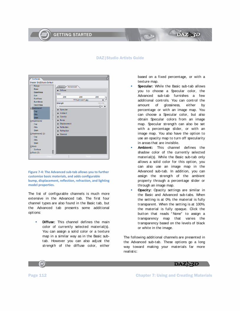
DAZ|Studio Artists Guide
Page 112 Chapter 7: Using and Creating Materials
Figure 7‐4: The Advanced sub‐tab allows you to further customize basic materials, and adds configurable bump, displacement, reflection, refraction, and lighting model properties.
The list of configurable channels is much more extensive in the Advanced tab. The first four channel types are also found in the Basic tab, but the Advanced tab presents some additional options:
Diffuse: This channel defines the main color of currently selected material(s). You can assign a solid color or a texture map in a similar way as in the Basic sub-tab. However you can also adjust the strength of the diffuse color, either
based on a fixed percentage, or with a texture map.
Specular: While the Basic sub-tab allows you to choose a Specular color, the Advanced sub-tab furnishes a few additional controls. You can control the amount of glossiness, either by percentage or with an image map. You can choose a Specular color, but also obtain Specular colors from an image map. Specular strength can also be set with a percentage slider, or with an image map. You also have the option to use an opacity map to turn off specularity in areas that are invisible.
Ambient: This channel defines the shadow color of the currently selected material(s). While the Basic sub-tab only allows a solid color for this option, you can also use an image map in the Advanced sub-tab. In addition, you can assign the strength of the ambient property through a percentage slider or through an image map.
Opacity: Opacity settings are similar in the Basic and Advanced sub-tabs. When the setting is at 0%, the material is fully transparent. When the setting is at 100%, the material is fully opaque. Click the button that reads “None” to assign a transparency map that varies the transparency based on the levels of black or white in the image.
The following additional channels are presented in the Advanced sub-tab. These options go a long way toward making your materials far more realistic:
DAZ|Studio Artists Guide
Chapter 7: Using and Creating Materials Page 113
Bump: This option adds a bumpy appearance to the portions of the object that are facing the camera. The amount of bumpiness is controlled by an image map that is usually grayscale. Negative Bump and Positive Bump sliders also provide additional control over the appearance of the material.
Displacement: Displacement is similar to a bump map with one exception. It actually displaces the geometry during render time. You’ll be able to see the effects of the displacement along the sides of the object in addition to the portions that directly face the camera. Displacement maps help you to create materials that make the geometry look far more intricate than it really is. The amount of displacement can be controlled through a slider, and/or through an image map (usually grayscale). There are also sliders to keep the amount of displacement within a minimum and maximum range.
Reflection: This channel controls how the surface of the material reflects light. You can assign a solid color or an image map to control the color of the reflections. In addition, the strength of the reflection can be controlled through a slider, or through an image map.
Refraction: Light bends when it shines through surfaces like glass or water. This channel controls the color of the light as it bends and shines through a surface. You can use a solid color or an image map to define the color or strength of the refraction.
Lighting Model: The lighting model option calculates the effects of different shader channels in response to light. You can make your material respond to light as if had a matte finish, or if were made of plastic, metal, glossy plastic, glossy metal, or skin.
Configuring Materials
One of the most obvious components of any material is its color- or, rather, colors. Several types of color make up a material. In addition, several settings control the strength of a given property.
Preparing for the Tutorials
In the tutorials that follow, you’ll experiment with the various types of material properties by applying them to a prop. To prepare your project file, create a new scene:
1. From the Pose/Animate Activity Tab, create a new scene using the File > New command.
2. From the Content Tab, navigate to the Studo > Scenes > Faerie Forest content folder, and double-click to load the Faerie Forest DAY scene.
3. Switch to the Scene Tab, and expand the Summerwood PP tree. Select Mushroom1 as the current object.
4. Use the Viewport and Camera controls in the viewport window to select Camera 3 as the current camera. Then click the

DAZ|Studio Artists Guide
Page 114 Chapter 7: Using and Creating Materials
Frame control to zoom into the mushroom as shown in Figure 7-5.
5. Choose View > Tabs > Surfaces to open the Surfaces Tab if necessary. Initially, the tab appears in a floating pane. You can leave it as a floating window and move it away from the Viewport , or you can click and drag the Surfaces Tab to dock it to the left or right side of your screen.
6. If the surface list does not appear in the upper portion of the Surfaces Tab, open the Surfaces Tab Option menu and check either the Surface List on Top or Surface List on Side option.
7. Expand the Surface List, and select Cap under Mushroom1, as shown in Figure 7-6.
NOTE!
Notice that nothing appears in the Surfaces Tab until you select a surface. When you select a surface, its settings appear in the Basic and Advanced sub-tabs. After you learn about how each material channel is configured in the Basic and Advanced sub-tabs, you’ll firm up your knowledge with a brief tutorial.
Figure 7‐5: Load the Faerie Forest DAY scene and zoom in to Mushroom1.
Figure 7‐6: Select the Cap material under the Mushroom1 heading.
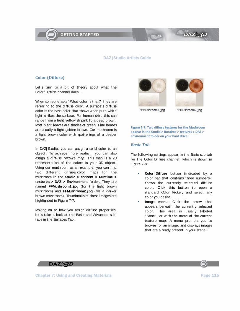
DAZ|Studio Artists Guide
Chapter 7: Using and Creating Materials Page 115
Color (Diffuse)
Let’s turn to a bit of theory about what the Color/Diffuse channel does …
When someone asks “What color is that?” they are referring to the diffuse color. A surface’s diffuse color is the base color that shows when pure white light strikes the surface. For human skin, this can range from a light yellowish pink to a deep brown. Most plant leaves are shades of green. Pine boards are usually a light golden brown. Our mushroom is a light brown color with spatterings of a deeper brown.
In DAZ|Studio, you can assign a solid color to an object. To achieve more realism, you can also assign a diffuse texture map. This map is a 2D representation of the colors in your 3D object. Using our mushroom as an example, you can find two different diffuse/color maps for the mushroom in the Studio > content > Runtime > textures > DAZ > Environment folder. They are named FFMushroom1.jpg (for the light brown mushroom) and FFMushroom2.jpg (for a darker brown mushroom). Thumbnails of these images are highlighted in Figure 7-7.
Moving on to how you assign diffuse properties, let’s take a look at the Basic and Advanced sub-tabs in the Surfaces Tab.
Figure 7‐7: Two diffuse textures for the Mushroom appear in the Studio > Runtime > textures > DAZ > Environment folder on your hard drive.
Basic Tab
The following settings appear in the Basic sub-tab for the Color|Diffuse channel, which is shown in Figure 7-8:
Color|Diffuse button (indicated by a color bar that contains three numbers): Shows the currently selected diffuse color. Click this button to open a standard Color Picker, and select any color you desire.
Image menu: Click the arrow that appears beneath the currently selected color. This area is usually labeled “None”, or with the name of the current texture map. A menu prompts you to browse for an image, and displays images that are already present in your scene.
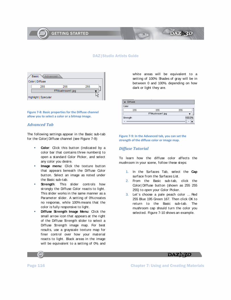
DAZ|Studio Artists Guide
Page 116 Chapter 7: Using and Creating Materials
Figure 7‐8: Basic properties for the Diffuse channel allow you to select a color or a bitmap image.
Advanced Tab
The following settings appear in the Basic sub-tab for the Color|Diffuse channel (see Figure 7-9):
Color: Click this button (indicated by a color bar that contains three numbers) to open a standard Color Picker, and select any color you desire.
Image menu: Click the texture button that appears beneath the Diffuse Color button. Select an image as noted under the Basic sub-tab.
Strength: This slider controls how strongly the Diffuse Color reacts to light. This slider works in the same manner as a Parameter slider. A setting of 0% creates no response, while 100% means that the color is fully responsive to light.
Diffuse Strength Image Menu: Click the small arrow icon that appears at the right of the Diffuse Strength slider to select a Diffuse Strength image map. For best results, use a grayscale texture map for finer control over how your material reacts to light. Black areas in the image will be equivalent to a setting of 0%, and
white areas will be equivalent to a setting of 100%. Shades of gray will be in between 0 and 100%, depending on how dark or light they are.
Figure 7‐9: In the Advanced tab, you can set the strength of the diffuse color or image map.
Diffuse Tutorial
To learn how the diffuse color affects the mushroom in your scene, follow these steps:
1. In the Surfaces Tab, select the Cap surface from the Surfaces List.
2. From the Basic sub-tab, click the Color|Diffuse button (shown as 255 255 255) to open your Color Picker.
3. Let’s choose a pale peach color … Red 255 Blue 195 Green 167. Then click OK to return to the Basic sub-tab. The mushroom cap should turn the color you selected. Figure 7-10 shows an example.

DAZ|Studio Artists Guide
Chapter 7: Using and Creating Materials Page 117
TIP!
In most cases, the diffuse color is set to white when used in combination with a diffuse texture map. You can use very subtle pastel colors to tint the texture map to a different color. Darker diffuse colors may significantly reduce or remove the effect of the underlying texture map.
Figure 7‐10: After changing the diffuse color of the mushroom cap to a pale peach, it darkens the texture map.
Highlight (Specular)
Now let’s examine the highlight, or specular surface property. In DAZ|Studio, the Specular channel controls the color of the highlights in an
object. Examples of specular highlights include the bright white glare-spot you might see when sunlight strikes stainless steel, or the faint sheen of human skin.
Glossy materials such as stainless steel show highlights differently than matte surfaces like human skin. For another example, glass usually shows a sharp white highlight when under bright light, whereas polished leather shows a softer sheen.
Basic Tab
The Basic sub-tab displays the following setting options for the Highlight/Specular channel (see Figure 7-11):
Figure 7‐11: The Basic sub‐tab allows you to change only the highlight (or specular) color.
Highlight/Specular: Click the button to open a standard Color Picker, and select any color you desire.
Advanced Tab
The Advanced sub-tab allows you to control the amount of specular highlights even further. Adjust glossiness with a slider, for example. You can also use image maps to control the color or strength of the highlights, and use an opacity map to turn off
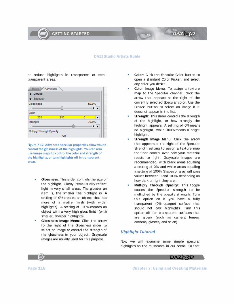
DAZ|Studio Artists Guide
Page 118 Chapter 7: Using and Creating Materials
or reduce highlights in transparent or semi-transparent areas.
Figure 7‐12: Advanced specular properties allow you to control the glossiness of the highlights. You can also use image maps to control the color and strength of the highlights, or turn highlights off in transparent areas.
Glossiness: This slider controls the size of the highlight. Glossy items usually reflect light in very small areas. The glossier an item is, the smaller the highlight is. A setting of 0% creates an object that has more of a matte finish (with wider highlights). A setting of 100% creates an object with a very high gloss finish (with smaller, sharper highlights).
Glossiness Image Menu: Click the arrow to the right of the Glossiness slider to select an image to control the strength of the glossiness in your object. Grayscale images are usually used for this purpose.
Color: Click the Specular Color button to open a standard Color Picker, and select any color you desire.
Color Image Menu: To assign a texture map to the Specular channel, click the arrow that appears at the right of the currently selected Specular color. Use the Browse button to select an image if it does not appear in the list.
Strength: This slider controls the strength of the highlight, or how strongly the highlight appears. A setting of 0% means no highlight, while 100% means a bright highlight.
Strength Image Menu: Click the arrow that appears at the right of the Specular Strength setting to assign a texture map for finer control over how your material reacts to light. Grayscale images are recommended, with black areas equaling a setting of 0%, and white areas equaling a setting of 100%. Shades of gray will pass values between 0 and 100%, depending on how dark or light they are.
Multiply Through Opacity: This toggle causes the Specular strength to be multiplied by the opacity strength. Turn this option on if you have a fully transparent (0% opaque) surface that should not cast highlights. Turn this option off for transparent surfaces that are glossy (such as camera lenses, corneas, glasses, and so on).
Highlight Tutorial
Now we will examine some simple specular highlights on the mushroom in our scene. So that

DAZ|Studio Artists Guide
Chapter 7: Using and Creating Materials Page 119
you can see the effect of the highlights on our mushroom, we’ll select a slightly different color. A nice sunny yellow will fit the scene quite nicely.
NOTE!
Highlights are dependant upon lights, so they may appear much different in the preview than they will when rendered. When you are creating materials with highlights, always perform renders as you adjust settings to make sure that the lights in your scene affect your settings properly.
The following tutorial assumes that you are starting from the settings that are already present in the Specular section when you first load the mushroom. To adjust the highlights on your mushroom, follow these steps:
1. In the Surfaces Tab, click the Specular Color button in the Advanced sub-tab.
2. Choose Yellow (Red 255, Green 255, Blue 0). When you render the mushroom with default lighting, you’ll notice a very soft yellow highlight near the bottom of the cap.
3. Increase the Specular Strength setting to 60%. Render again and you will notice that the highlight is now a lot stronger around the base.
4. To see what the Glossiness slider does, reduce its setting to around 15 or 16% and render again. You’ll notice that the highlight now covers a wider area and almost overpowers the mushroom.
5. Go back and forth between the Specular Strength and Glossiness sliders until you get the results you like. Figure 7-13 shows the settings we arrived at (50% Glossiness and 70% Specular Strength), alongside an accompanying render.
Figure 7‐13: After making adjustments to the specular color of the mushroom cap, it looks nice and sunny.
Shadow (Ambient)
Ambient color is frequently used in 3D graphics to compensate for the fact that lighting in 3D environments only approximates real-world lighting. As a result, your materials frequently require additional parameters and adjustments to obtain the most realistic results when you render them.
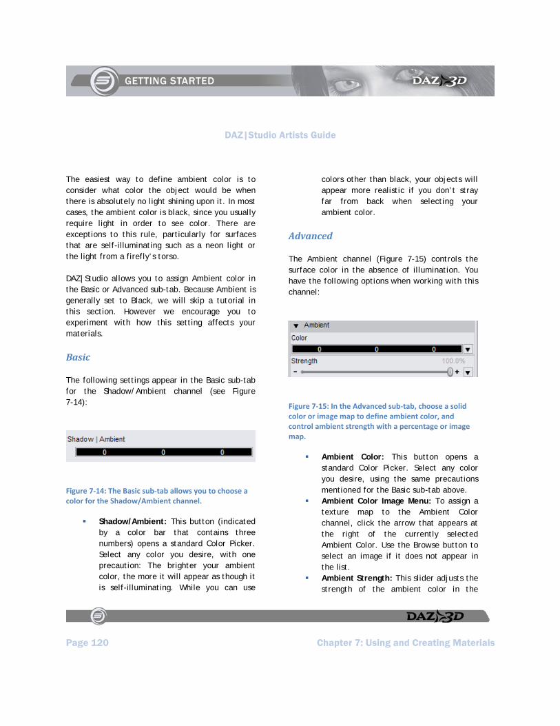
DAZ|Studio Artists Guide
Page 120 Chapter 7: Using and Creating Materials
The easiest way to define ambient color is to consider what color the object would be when there is absolutely no light shining upon it. In most cases, the ambient color is black, since you usually require light in order to see color. There are exceptions to this rule, particularly for surfaces that are self-illuminating such as a neon light or the light from a firefly’s torso.
DAZ|Studio allows you to assign Ambient color in the Basic or Advanced sub-tab. Because Ambient is generally set to Black, we will skip a tutorial in this section. However we encourage you to experiment with how this setting affects your materials.
Basic
The following settings appear in the Basic sub-tab for the Shadow/Ambient channel (see Figure 7-14):
Figure 7‐14: The Basic sub‐tab allows you to choose a color for the Shadow/Ambient channel.
Shadow/Ambient: This button (indicated by a color bar that contains three numbers) opens a standard Color Picker. Select any color you desire, with one precaution: The brighter your ambient color, the more it will appear as though it is self-illuminating. While you can use
colors other than black, your objects will appear more realistic if you don’t stray far from back when selecting your ambient color.
Advanced
The Ambient channel (Figure 7-15) controls the surface color in the absence of illumination. You have the following options when working with this channel:
Figure 7‐15: In the Advanced sub‐tab, choose a solid color or image map to define ambient color, and control ambient strength with a percentage or image map.
Ambient Color: This button opens a standard Color Picker. Select any color you desire, using the same precautions mentioned for the Basic sub-tab above.
Ambient Color Image Menu: To assign a texture map to the Ambient Color channel, click the arrow that appears at the right of the currently selected Ambient Color. Use the Browse button to select an image if it does not appear in the list.
Ambient Strength: This slider adjusts the strength of the ambient color in the
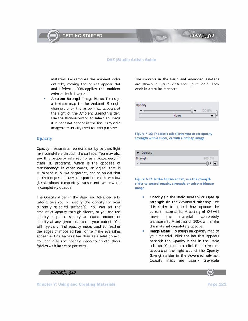
DAZ|Studio Artists Guide
Chapter 7: Using and Creating Materials Page 121
material. 0% removes the ambient color entirely, making the object appear flat and lifeless. 100% applies the ambient color at its full value.
Ambient Strength Image Menu: To assign a texture map to the Ambient Strength channel, click the arrow that appears at the right of the Ambient Strength slider. Use the Browse button to select an image if it does not appear in the list. Grayscale images are usually used for this purpose.
Opacity
Opacity measures an object’s ability to pass light rays completely through the surface. You may also see this property referred to as transparency in other 3D programs, which is the opposite of transparency: in other words, an object that is 100% opaque is 0% transparent, and an object that it 0% opaque is 100% transparent. Sheet window glass is almost completely transparent, while wood is completely opaque.
The Opacity slider in the Basic and Advanced sub-tabs allows you to specify the opacity for your currently selected surface(s). You can set the amount of opacity through sliders, or you can use opacity maps to specify an exact amount of opacity at any given location in your object. You will typically find opacity maps used to feather the edges of modeled hair, or to make eyelashes appear as fine hairs rather than as a solid object. You can also use opacity maps to create sheer fabrics with intricate patterns.
The controls in the Basic and Advanced sub-tabs are shown in Figure 7-16 and Figure 7-17. They work in a similar manner:
Figure 7‐16: The Basic tab allows you to set opacity strength with a slider, or with a bitmap image.
Figure 7‐17: In the Advanced tab, use the strength slider to control opacity strength, or select a bitmap image.
Opacity (in the Basic sub-tab) or Opacity Strength (in the Advanced sub-tab): Use this slider to control how opaque the current material is. A setting of 0% will make the material completely transparent. A setting of 100% will make the material completely opaque.
Image Menu: To assign an opacity map to your material, click the bar that appears beneath the Opacity slider in the Basic sub-tab. You can also click the arrow that appears at the right side of the Opacity Strength slider in the Advanced sub-tab. Opacity maps are usually grayscale

DAZ|Studio Artists Guide
Page 122 Chapter 7: Using and Creating Materials
images, with black designating areas that will be fully transparent, and white designating areas that will be fully opaque. Any shades of gray in the image map will result in areas that are partially transparent, depending on how close they are to black or white.
Opacity Tutorial
There are a limited number of opacity maps to choose from in the content that is furnished with DAZ|Studio. The end result in this tutorial won’t be practical, but the steps you learn here give you the opportunity to see how opacity maps affect the appearance of an object. Try the following steps:
1. Return now to the Faerie Forest DAY scene that you have loaded in your viewport.
2. From the Surfaces List, select the Cap material for the mushroom if necessary.
3. From the Basic sub-tab, move the Opacity slider toward the left, or enter a value of 25 in the number field and press Enter.
4. When you look through camera 3 in the scene, you’ll notice that you can see right through the mushroom cap.
5. To see the best results, choose Render > Render to render the mushroom. Your results should look similar to Figure 7-18.
Figure 7‐18: After reducing the opacity of the cap to 25% you can see right through it.
Now let’s see what happens when we add an opacity map. Granted, you rarely see a transparent mushroom, so this exercise is just for demonstration purposes:
1. Switch to the Advanced sub-tab in the Surfaces list.
2. Locate the Opacity section in the Advanced sub-tab. Click the arrow at the right side of the slider to display the Image Menu options. Choose Browse for Image, and locate the Studio > Content > Runtime > Textures > DAZ > Characters > MilWom > V3Maps folder. Select the V3Lo_Trans.jpg image as the opacity map and click Open.
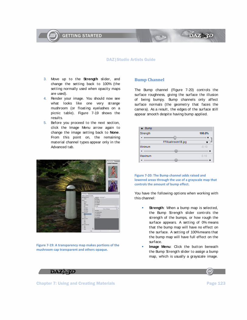
DAZ|Studio Artists Guide
Chapter 7: Using and Creating Materials Page 123
3. Move up to the Strength slider, and change the setting back to 100% (the setting normally used when opacity maps are used).
4. Render your image. You should now see what looks like one very strange mushroom (or floating eyelashes on a picnic table). Figure 7-19 shows the results.
5. Before you proceed to the next section, click the Image Menu arrow again to change the image setting back to None. From this point on, the remaining material channel types appear only in the Advanced tab.
Figure 7‐19: A transparency map makes portions of the mushroom cap transparent and others opaque.
Bump Channel
The Bump channel (Figure 7-20) controls the surface roughness, giving the surface the illusion of being bumpy. Bump channels only affect surface normals (the geometry that faces the camera). As a result, the edges of the surface still appear smooth despite having bump applied.
Figure 7‐20: The Bump channel adds raised and lowered areas through the use of a grayscale map that controls the amount of bump effect.
You have the following options when working with this channel:
Strength: When a bump map is selected, the Bump Strength slider controls the strength of the bumps, or how rough the surface appears. A setting of 0% means that the bump map will have no effect on the surface. A setting of 100% means that the bump map will have full effect on the surface.
Image Menu: Click the button beneath the Bump Strength slider to assign a bump map, which is usually a grayscale image.
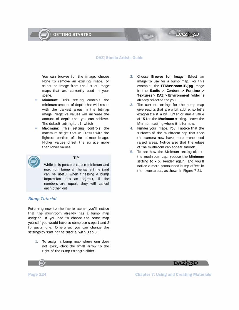
DAZ|Studio Artists Guide
Page 124 Chapter 7: Using and Creating Materials
You can browse for the image, choose None to remove an existing image, or select an image from the list of image maps that are currently used in your scene.
Minimum: This setting controls the minimum amount of depth that will result with the darkest areas in the bitmap image. Negative values will increase the amount of depth that you can achieve. The default setting is -.1, which
Maximum: This setting controls the maximum height that will result with the lightest portion of the bitmap image. Higher values offset the surface more than lower values.
TIP!
While it is possible to use minimum and maximum bump at the same time (and can be useful when finessing a bump impression into an object), if the numbers are equal, they will cancel each other out.
Bump Tutorial
Returning now to the faerie scene, you’ll notice that the mushroom already has a bump map assigned. If you had to choose the same map yourself you would have to complete steps 1 and 2 to assign one. Otherwise, you can change the settings by starting the tutorial with Step 3:
1. To assign a bump map where one does not exist, click the small arrow to the right of the Bump Strength slider.
2. Choose Browse for Image. Select an image to use for a bump map. For this example, the FFMushroom1B.jpg image in the Studio > Content > Runtime > Textures > DAZ > Environment folder is already selected for you.
3. The current settings for the bump map give results that are a bit subtle, so let’s exaggerate it a bit. Enter or dial a value of .5 for the Maximum setting. Leave the Minimum setting where it is for now.
4. Render your image. You’ll notice that the surfaces of the mushroom cap that face the camera now have more pronounced raised areas. Notice also that the edges of the mushroom cap appear smooth.
5. To see how the Minimum setting affects the mushroom cap, reduce the Minimum setting to -.5. Render again, and you’ll notice a more pronounced bump effect in the lower areas, as shown in Figure 7-21.

DAZ|Studio Artists Guide
Chapter 7: Using and Creating Materials Page 125
Figure 7‐21: Increase the Minimum and Maximum bump settings to create bumps that are more pronounced.
Displacement Channel
The Displacement channel (Figure 7-22) controls the surface roughness. While the settings are similar to those used in a Bump map, there is one key difference. Unlike the bump channel, displacement affects the underlying geometry of the surface. This means that the edges of the surface will also look rough.
You have the following options when working with the displacement channel:
Figure 7‐22: Displacement settings in the Advanced Tab allow you to assign a bitmap image and set minimum and maximum values.
Strength: Click the button to assign a displacement map, which is usually a grayscale image. You can browse for the image, choose None to remove an existing image, or select an image from the list of image maps that are currently used in your scene.
Minimum: This setting provides a “low cutoff” setting for the lower areas of your displacement map. If the setting is too high, it can cause your geometry to appear much distorted and increases render time.
Maximum: This setting provides a “high cutoff” for the higher areas of your displacement map. If the setting is too high, it can cause your geometry to appear much distorted and increases render time.
Displacement Tutorial
Now you’ll turn off the bump map and use the same image map as a displacement map. Follow these steps:

DAZ|Studio Artists Guide
Page 126 Chapter 7: Using and Creating Materials
1. So that you can see the differences between bump and displacement, reset the Bump Strength image map back to None so that it will have no effect on the displacement channel.
2. To assign the displacement map, click the Displacement Strength button.
3. Select an image to use for a displacement map. You’ll use the same image that you used for the bump map, which should still be available in the Image Menu. Select the FFMushroom1B.jpg image.
4. Use the Strength slider or numeric input field to increase the displacement strength setting to 100%.
5. Render your image. You should see the surfaces of the mushroom cap that face the camera now appear to have raised and lowered surfaces, similar to when the bump map was used. However, unlike the bump map, you can also see that the edges of the object are also affected by the displacement.
6. You can adjust a few different settings to increase or decrease the effect of the displacement map:
Increase or decrease the Displacement Strength slider setting, which is adjustable from 0 to 200%
Increase or decrease the Minimum and/or Maximum Displacement settings very slightly, as a little goes a long way. In the example shown below, the Minimum Displacement setting was reduced from -1.00 to -1.25, and the Maximum Displacement
setting was increased from 1.00 to 1.25.
7. Render again, and you’ll notice a more pronounced bump effect, as shown in Figure 7-23. While it’s not really convincing for a realistic mushroom, you are able to see how the appearance of simple geometry can be totally transformed with displacement maps, especially around the edges of the mushroom cap.
Figure 7‐23: Displacement maps can add a lot of intricate detail to objects that are created with simple geometry.

DAZ|Studio Artists Guide
Chapter 7: Using and Creating Materials Page 127
Reflection
The Reflection channel (Figure 7-24) controls the surface reflection. This component controls the color that the object casts into reflected light. When you add Reflection properties to your material, either by entering a value, using an image map, or both, one of two things will happen at render time:
If you specify a reflection color map, DAZ|Studio uses that map as a cubic environment map.
If you do not specify a map, DAZ|Studio invokes a raytracer during rendering. The raytracer examines the surroundings of the object and reflects the environment of the scene back into the reflection on the material.
You have the following options when working with this channel:
Figure 7‐24: Reflections can be a solid color or driven by an image map. The strength of the reflection is controlled by a slider or by an image map.
Color: Click this button to open a standard Color Picker. Select the desired reflection color for surface. This color
multiplies through any map you might apply, which means that the base color will blend through the map.
Color Image Map: Click the arrow that appears to the right of the Reflection Color slider to assign a texture map that controls the reflection colors. Reflection maps are often created from pictures of the surrounding environment. Images such as skies, clouds, or water are commonly used for reflections.
Strength: The Reflection Strength slider controls how strongly the surface geometry redirects light. A setting of 0% creates a material that has no reflective properties (such as wood). A setting of 100% creates a surface that is fully reflective (like a smooth polished mirror).
Strength Image Map: Click the arrow at the right of the Reflection Strength slider to control the amount of reflection with an image map. A grayscale image is usually used for this purpose, with black being equal to a setting of 0%, and white being equal to a setting of 100%.
Reflection Tutorial
You can give nearly anything a reflective (or in many cases a perfectly mirrored) finish. You can also use reflection maps to specify areas of varying reflectivity, to do various things such as simulating a cracked mirror, rusted metal, etc. You’ll have to render the image to see the results, since reflections and lighting are processed at render time.
DAZ|Studio Artists Guide
Page 128 Chapter 7: Using and Creating Materials
Also, when it comes to creating scenes that contain reflective materials, remember that the figures and props in DAZ|Studio are three-dimensional. When you position a figure in front of a mirror, make sure that the back side of the figure is just as well-positioned as the front if you want to reflect the back side. Multiple reflections can come from lights or other objects that are positioned around the object you want to reflect.
You can easily create a mirror by adding a flat plane into your scene and setting the Specular and Reflection properties as outlined in the following tutorial:
If you want a reflective floor, position and scale the object directly beneath the objects you want to reflect.
If you want a mirror or reflective wall, rotate the plane accordingly. As you position the plane, look at the scene from all angles to make sure that the mirror is positioned properly in relation to the object you want to reflect.
In the case of our Faerie Forest Day scene, we’ll make the ground reflective. This will cause the ground to have the appearance of water that reflects the surroundings in the scene.
To make the ground reflective, follow these steps:
1. From the Surfaces Tab, scroll down and expand the Summerwood PP branch of the tree. Select the Tiling Terrain surface.
2. When creating mirrored surfaces, you can set the Diffuse Color of the plane to any color you like. In the case of our terrain, an image map is used to define the diffuse colors of the ground. The reflections will combine into this texture so that you can still see the ground texture, but you’ll also see the surrounding scenery reflected within it.
3. In the Specular section, set Glossiness to 99%. Set Specular Color to White, and Specular Strength to 100%.
4. In the Ambient section, set Ambient Color to Black, at 100% Ambient Strength.
5. In the Reflection section, set the Reflection Color to White, to reflect the colors in your scene with the most accuracy. Set Reflection Strength to 100%.
6. Render your scene. The rendering will take more time than the previous renders you performed, because DAZ|Studio is examining the surrounding objects and calculating the reflections that will appear in the ground. After the render is complete, you should see the object or objects reflected in your mirrored surface as shown in Figure 7-25.

DAZ|Studio Artists Guide
Chapter 7: Using and Creating Materials Page 129
Figure 7‐25: With a reflective ground, the mushroom looks like it’s sitting in the midst of a pond. The mushroom and the other scene objects are reflected in the ground.
Refraction
Light rays bend when passing through objects of differing densities. For example, light bends when it passes through air into water. Refraction makes objects appear as though they are in a different location than they really are because of the bending effect.
When you add refraction strength with a numerical value, an image map, or a combination of both, one of two things can happen at render time:
If you use a refraction map, DAZ|Studio uses that map as a cubic environment map.
If you do not specify a map, DAZ|Studio will invoke the raytracer to use surrounding materials in the refraction calculations.
The Refraction channel (Figure 7-26) controls the surface light bending. You have the following options when working with this channel:
Figure 7‐26: Refraction properties control how much light bends when it passes through an object.
Color: Click the Refraction Color button to select a color with the standard Color Picker. Keep in mind that light can sometimes change color as it bends (think of white light passing through a prism). The refraction color multiplies through any map you might apply, which means that the base color will blend through the map.
Color Image Map: Click the arrow at the right of the Refraction Color button to choose an image map that defines the refraction color.
Strength: The Refraction Strength slider controls how much the light bending

DAZ|Studio Artists Guide
Page 130 Chapter 7: Using and Creating Materials
effect (or the index of refraction) is evident. A setting of 0% means that the refraction is not visible, while 100% means that the refraction effect is fully visible
Strength Image Map: Click the arrow at the right of the Refraction Strength slider to control the strength of the refraction with an image map.
Index of Refraction: This setting determines the amount of bending that occurs when light passes through the object. Higher settings create more bending. The following are some refraction indices for some common materials:
Perfect Vacuum: 1.00000 Air (at sea level on a calm day):
1.00029 Ice (frozen clear ice): 1.31 Water (at room temperature, or 20
degrees Celsius): 1.33 Acetone: 1.36 Sugar solution(30%): 1.38 Sugar solution (80%): 1.49 Sodium chloride (salt): 1.54 Polystyrene: 1.55-1.59 Sapphire: 1.77 Diamond: 2.417
Refraction Tutorial
When you stand in a pond or lake and look down at the fish, you are observing the effects of refraction. Thanks to refraction, the fish appear to be in a different location than they actually are. You can also use refraction to simulate a small or
much exaggerated magnifying lens effect, as you’ll see in the following tutorial.
Let’s use the mushroom cap to refract the surrounding objects. We’ll have to remove the existing textures from the cap and adjust some other properties to make it work:
1. In the Surfaces List, scroll back up to Mushroom1, and select the Cap.
2. In the Advanced Surfaces Tab, go to the Diffuse section and remove the diffuse color map by setting it to None. Set the diffuse color back to white.
3. In the Displacement section, remove the image map by setting it to None.
4. Select the Gills of the Mushroom. Remove the Diffuse and Bump texture maps by setting them to none. Repeat these steps for the mushroom Stem.
5. Set the following properties for the Cap, Gills and the Stem of the mushroom:
Diffuse Strength: 0% Specular Glossiness: 0% Specular Strength: 0% Ambient Color: White Ambient Strength: 0%. Opacity Strength: 1.0% or lower
(otherwise you end up with a ‘fisheye’ effect where the visible parts of the mushroom balloon out to take the place of the cap’s outer curve).
Bump Strength: None (0%) Displacement Strength: None (0%) Reflection Strength: 0% Refraction Color: White
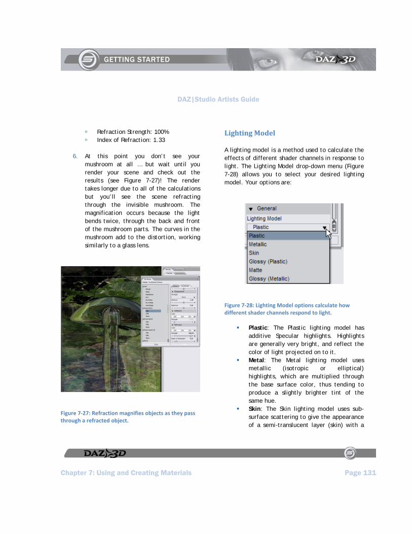
DAZ|Studio Artists Guide
Chapter 7: Using and Creating Materials Page 131
Refraction Strength: 100% Index of Refraction: 1.33
6. At this point you don’t see your mushroom at all … but wait until you render your scene and check out the results (see Figure 7-27)! The render takes longer due to all of the calculations but you’ll see the scene refracting through the invisible mushroom. The magnification occurs because the light bends twice, through the back and front of the mushroom parts. The curves in the mushroom add to the distortion, working similarly to a glass lens.
Figure 7‐27: Refraction magnifies objects as they pass through a refracted object.
Lighting Model
A lighting model is a method used to calculate the effects of different shader channels in response to light. The Lighting Model drop-down menu (Figure 7-28) allows you to select your desired lighting model. Your options are:
Figure 7‐28: Lighting Model options calculate how different shader channels respond to light.
Plastic: The Plastic lighting model has additive Specular highlights. Highlights are generally very bright, and reflect the color of light projected on to it.
Metal: The Metal lighting model uses metallic (isotropic or elliptical) highlights, which are multiplied through the base surface color, thus tending to produce a slightly brighter tint of the same hue.
Skin: The Skin lighting model uses sub-surface scattering to give the appearance of a semi-translucent layer (skin) with a

DAZ|Studio Artists Guide
Page 132 Chapter 7: Using and Creating Materials
blue sheen and a red opaque sub layer (blood/muscle).
Glossy (Plastic): The Glossy (plastic) lighting model uses a Fresnel function to make the surface act more reflective at glancing angles. It also calculates specularity in a way that produces a more uniformly bright highlight (sharper), thus making the surface look glossy. Eyeballs are a great example.
Matte: The Matte lighting model completely ignores the Specular channel.
Glossy (Metallic): The Glossy (metallic) lighting model is similar to the Glossy (plastic) model, but the calculations are adjusted to produce a gloss that mimics the gloss of highly-polished metal.
Saving Materials
After you customize or create a new material, you’ll probably want to save it to one of your content folders so that you can reuse it at any time. To save a material, follow these steps:
1. Select the item in the scene that contains the material(s) you want to save.
2. Choose File > Save As > Materials Preset. The Filtered Save dialog appears.
3. Locate the folder to which you want to save the preset:
To save the material to the default DAZ|Studio folder, locate your file in any folder that appears beneath the Studio > Content folders that were installed with DAZ|Studio.
To save the material to an external folder that is recognized as a content folder, locate your file in any external folders that you have set up in the Directories folder of the Preferences dialog (see Edit > Preferences in Chapter 6, “Command and Toolbar Reference.”)
To save the material to a new folder, create the new folder during the Save process, and then later use the Edit > Preferences command to add the new folder to your Directories list so that you can see the new material in the Content Tab.
4. Enter a name for the new material and press Save to continue. The Materials Preset Options dialog shown in Figure 7-29 appears. Use one of the following two options to save your material:
To save all materials and settings associated with the current object, choose the All Surface Properties option and click Accept. We recommend using this option until you become more familiar with DAZ|Studio and material settings in general.
To select specific materials and settings, choose the Advanced option, and then expand or collapse the trees to select the specific properties you want to save. Click Accept when you’re done with your selections.
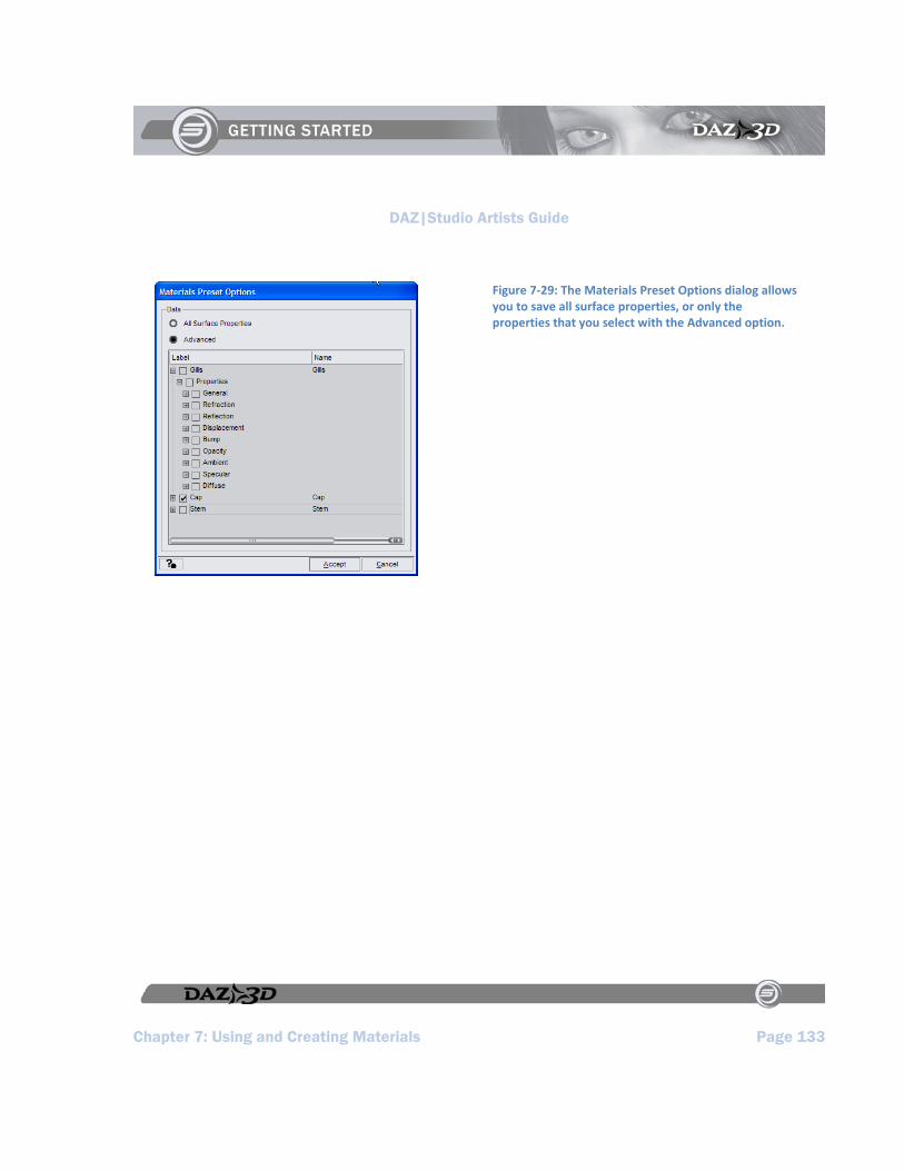
DAZ|Studio Artists Guide
Chapter 7: Using and Creating Materials Page 133
Figure 7‐29: The Materials Preset Options dialog allows you to save all surface properties, or only the properties that you select with the Advanced option.

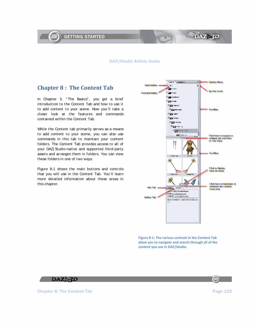
DAZ|Studio Artists Guide
Chapter 8: The Content Tab Page 135
Chapter 8 : The Content Tab
In Chapter 3, “The Basics”, you got a brief introduction to the Content Tab and how to use it to add content to your scene. Now you’ll take a closer look at the features and commands contained within the Content Tab.
While the Content tab primarily serves as a means to add content to your scene, you can also use commands in this tab to maintain your content folders. The Content Tab provides access to all of your DAZ|Studio-native and supported third-party assets and arranges them in folders. You can view these folders in one of two ways.
Figure 8-1 shows the main buttons and controls that you will use in the Content Tab. You’ll learn more detailed information about these areas in this chapter.
Figure 8‐1: The various controls in the Content Tab allow you to navigate and search through all of the content you use in DAZ|Studio.
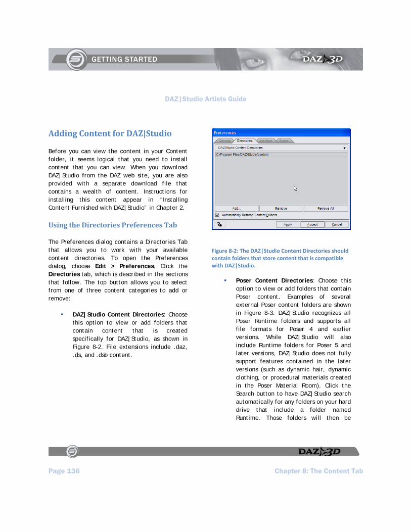
DAZ|Studio Artists Guide
Page 136 Chapter 8: The Content Tab
Adding Content for DAZ|Studio
Before you can view the content in your Content folder, it seems logical that you need to install content that you can view. When you download DAZ|Studio from the DAZ web site, you are also provided with a separate download file that contains a wealth of content. Instructions for installing this content appear in “Installing Content Furnished with DAZ|Studio” in Chapter 2.
Using the Directories Preferences Tab
The Preferences dialog contains a Directories Tab that allows you to work with your available content directories. To open the Preferences dialog, choose Edit > Preferences. Click the Directories tab, which is described in the sections that follow. The top button allows you to select from one of three content categories to add or remove:
DAZ|Studio Content Directories: Choose this option to view or add folders that contain content that is created specifically for DAZ|Studio, as shown in Figure 8-2. File extensions include .daz, .ds, and .dsb content.
Figure 8‐2: The DAZ|Studio Content Directories should contain folders that store content that is compatible with DAZ|Studio.
Poser Content Directories: Choose this option to view or add folders that contain Poser content. Examples of several external Poser content folders are shown in Figure 8-3. DAZ|Studio recognizes all Poser Runtime folders and supports all file formats for Poser 4 and earlier versions. While DAZ|Studio will also include Runtime folders for Poser 5 and later versions, DAZ|Studio does not fully support features contained in the later versions (such as dynamic hair, dynamic clothing, or procedural materials created in the Poser Material Room). Click the Search button to have DAZ|Studio search automatically for any folders on your hard drive that include a folder named Runtime. Those folders will then be
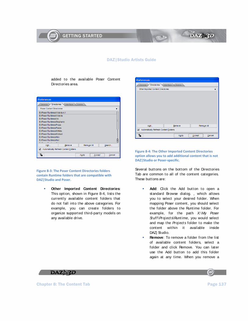
DAZ|Studio Artists Guide
Chapter 8: The Content Tab Page 137
added to the available Poser Content Directories area.
Figure 8‐3: The Poser Content Directories folders contain Runtime folders that are compatible with DAZ|Studio and Poser.
Other Imported Content Directories: This option, shown in Figure 8-4, lists the currently available content folders that do not fall into the above categories. For example, you can create folders to organize supported third-party models on any available drive.
Figure 8‐4: The Other Imported Content Directories option allows you to add additional content that is not DAZ|Studio or Poser‐specific.
Several buttons on the bottom of the Directories Tab are common to all of the content categories. These buttons are:
Add: Click the Add button to open a standard Browse dialog. , which allows you to select your desired folder. When mapping Poser content, you should select the folder above the Runtime folder. For example, for the path X:\My Poser Stuff\Projects\Runtime, you would select and map the Projects folder to make the content within it available inside DAZ|Studio.
Remove: To remove a folder from the list of available content folders, select a folder and click Remove. You can later use the Add button to add this folder again at any time. When you remove a
DAZ|Studio Artists Guide
Page 138 Chapter 8: The Content Tab
folder from the DAZ|Studio content list, you do not actually remove the data within the folder on your hard disk.
Remove All: To remove all folders stored in the current list, click Remove All. You will not actually remove the data within the folders on your hard disk..
Automatically Refresh Content Folders: This option is useful if you want to add assets while DAZ|Studio is running. You won’t have to switch in and out of a given folder to refresh its content list. The refresh time is dependent on how many expanded folders there are in the Content Tab, computer speed, and (if applicable) network traffic conditions. It is also useful for teams who are sharing assets from a single source, such as on a common network drive. Note that using this option may slow down interface interaction while the update occurs, depending on network speed if the content being refreshed is on a network drive.
Click for Interactive Help: Click this button, and then click an item in the Preferences dialog to view a pop-up window that displays information about that feature.
Apply: Click the Apply button to apply any changes you have made to your content directories. You can then make changes in other Preferences tabs.
Accept: Click the Accept button to accept any changes you have made to your content directories. This option will close the Preferences dialog.
Cancel: Click Cancel to exit the Preferences dialog immediately. You will lose any unsaved changes made to your content folders.
Installing DAZ Content
When you purchase content from DAZ 3D, it is distributed in Windows executable files (EXE extension) or in SIT format for Macintosh users. The setup process is self-explanatory, as the setup wizard guides you through the process of choosing the folders that will store your content. You can install your content in the default DAZ|Studio content folder, or into an external Content directory in any folder that lies outside the DAZ|Studio installation folder. If you install your content into a folder that DAZ|Studio does not yet recognize as a content folder, you may need to use the Edit > Preferences command as described earlier to add the new content folder to your directory lists.
Another important thing to mention is that DAZ content is compatible with DAZ|Studio and Poser. Products that are more recent may include a separate file that contains the DAZ|Studio-specific files such as material settings. When you order a product from DAZ, check to see if there are separate files included with the product that have the letters DS toward the end of the file name. Install the files along with the base product if you plan on using the product in DAZ|Studio.

DAZ|Studio Artists Guide
Chapter 8: The Content Tab Page 139
Installing ThirdParty Content
When you purchase content from third party developers that sell their products at stores other than DAZ, they are typically distributed in ZIP files. Most often, they are configured to be compatible with the Poser® library structure, meaning that all files are placed beneath a folder that begins with a Runtime folder. Many users of DAZ|Studio extract these files into external folders so that they can use the same content in both DAZ|Studio and Poser. Even if you intend on using this content in DAZ|Studio, it may be beneficial to install them to an external folder of your choosing. Afterward, you will have to use the Edit > Preferences command to add the new Poser content folder to your directory lists.
Content Viewing and Navigation
The Content Tab allows you to view your content in List View or Tree View. You can also specify the size of the icons used in the lower portion of the tab. All of these options appear in the Content Tab Options menu, described below.
Content Tab Options
The Content Tab Options menu appears in the upper-right corner of the Content Tab. Click the Content Tab Options button to open the Content Tab Options menu shown in Figure 8-5.
Figure 8‐5: The Content Tab options menu allows you to choose how your content is displayed in the tab.
The commands are as follows:
View Folders as List: Displays your content folders in a list of columns, commonly seen in Macintosh-based systems.
View Folders as Tree: Displays your content folders as a hierarchical tree.
View Large File Icons: Displays content and folder icons at an enlarged size, with the name of the content file appearing beneath the icon.
View Small File Icons: Displays content and folder icons at a reduced size, with the name of the content file appearing to the right of the icon.
Delete: Removes the selected content from your DAZ|Studio Library.
Close: Closes the Content Tab.
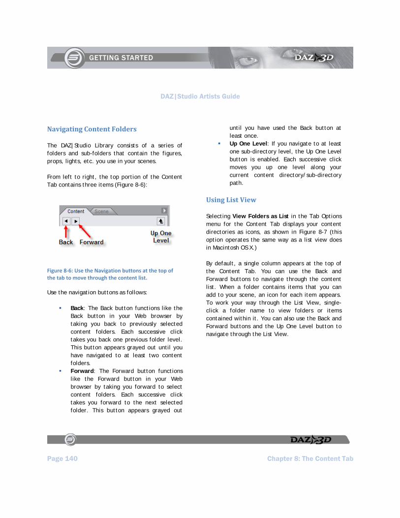
DAZ|Studio Artists Guide
Page 140 Chapter 8: The Content Tab
Navigating Content Folders
The DAZ|Studio Library consists of a series of folders and sub-folders that contain the figures, props, lights, etc. you use in your scenes.
From left to right, the top portion of the Content Tab contains three items (Figure 8-6):
Figure 8‐6: Use the Navigation buttons at the top of the tab to move through the content list.
Use the navigation buttons as follows:
Back: The Back button functions like the Back button in your Web browser by taking you back to previously selected content folders. Each successive click takes you back one previous folder level. This button appears grayed out until you have navigated to at least two content folders.
Forward: The Forward button functions like the Forward button in your Web browser by taking you forward to select content folders. Each successive click takes you forward to the next selected folder. This button appears grayed out
until you have used the Back button at least once.
Up One Level: If you navigate to at least one sub-directory level, the Up One Level button is enabled. Each successive click moves you up one level along your current content directory/sub-directory path.
Using List View
Selecting View Folders as List in the Tab Options menu for the Content Tab displays your content directories as icons, as shown in Figure 8-7 (this option operates the same way as a list view does in Macintosh OS X.)
By default, a single column appears at the top of the Content Tab. You can use the Back and Forward buttons to navigate through the content list. When a folder contains items that you can add to your scene, an icon for each item appears. To work your way through the List View, single-click a folder name to view folders or items contained within it. You can also use the Back and Forward buttons and the Up One Level button to navigate through the List View.

DAZ|Studio Artists Guide
Chapter 8: The Content Tab Page 141
Figure 8‐7: In List View, you can scroll through the content in your list using the navigation buttons or by clicking the folder you want to go into.
For convenience, you can widen the Content Tab to see two folder columns, as shown in Figure 8-8. The left column displays the current folder level while the right column displays any folder(s) underneath the folder currently selected in the left column. For example, if you have the default Victoria folder selected in the left column, the right column will display the Clothing, Hair, and Poses sub-folders.
Figure 8‐8: You might find it easier to navigate in list view when you widen the Content Tab to display two columns in the content list.
Using Tree View
You can also view your folders in a tree view. To do so, choose View Folders as Tree from the Content Tab Options menu. This view displays your content folders as a hierarchical tree as shown in Figure 8-9. This view allows you to jump quickly to any content folder on any level of your Library. Content within the currently selected folder appears in the bottom portion of the Content Tab as described above.
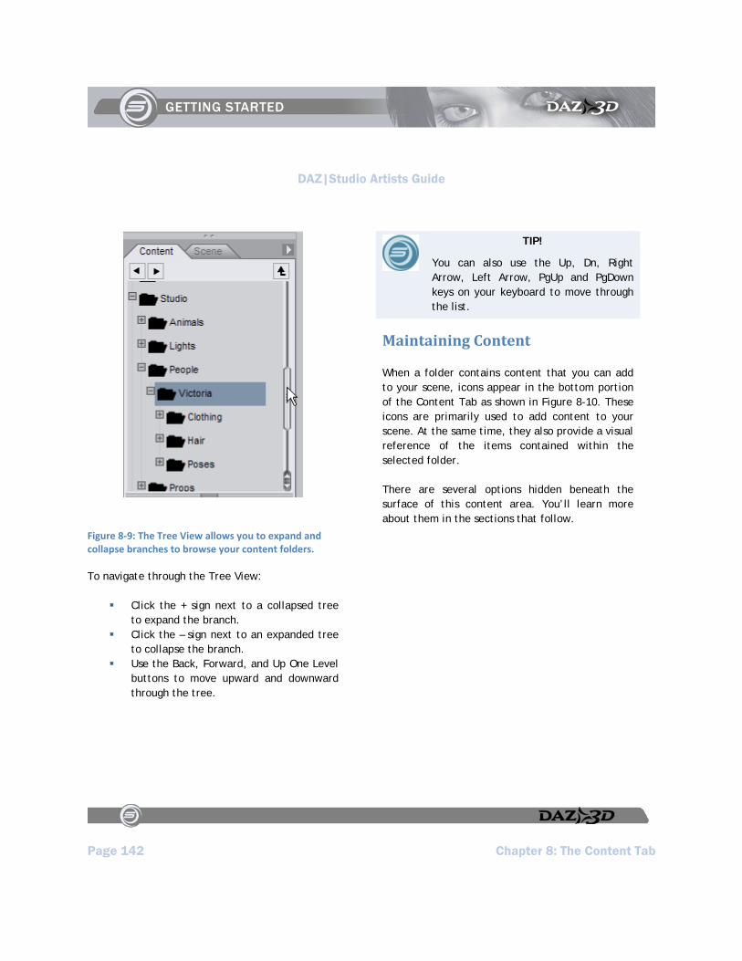
DAZ|Studio Artists Guide
Page 142 Chapter 8: The Content Tab
Figure 8‐9: The Tree View allows you to expand and collapse branches to browse your content folders.
To navigate through the Tree View:
Click the + sign next to a collapsed tree to expand the branch.
Click the – sign next to an expanded tree to collapse the branch.
Use the Back, Forward, and Up One Level buttons to move upward and downward through the tree.
TIP!
You can also use the Up, Dn, Right Arrow, Left Arrow, PgUp and PgDown keys on your keyboard to move through the list.
Maintaining Content
When a folder contains content that you can add to your scene, icons appear in the bottom portion of the Content Tab as shown in Figure 8-10. These icons are primarily used to add content to your scene. At the same time, they also provide a visual reference of the items contained within the selected folder.
There are several options hidden beneath the surface of this content area. You’ll learn more about them in the sections that follow.
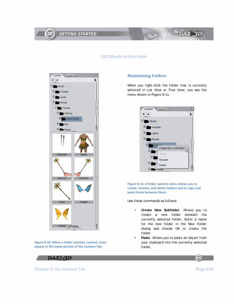
DAZ|Studio Artists Guide
Chapter 8: The Content Tab Page 143
Figure 8‐10: When a folder contains content, icons appear in the lower portion of the Content Tab.
Maintaining Folders
When you right-click the folder that is currently selected in List View or Tree View, you see the menu shown in Figure 8-11.
Figure 8‐11: A folder options menu allows you to create, rename, and delete folders and to copy and paste items between them.
Use these commands as follows:
Create New Subfolder: Allows you to create a new folder beneath the currently selected folder. Enter a name for the new folder in the New Folder dialog and choose OK to create the folder.
Paste: Allows you to paste an object from your clipboard into the currently selected folder.
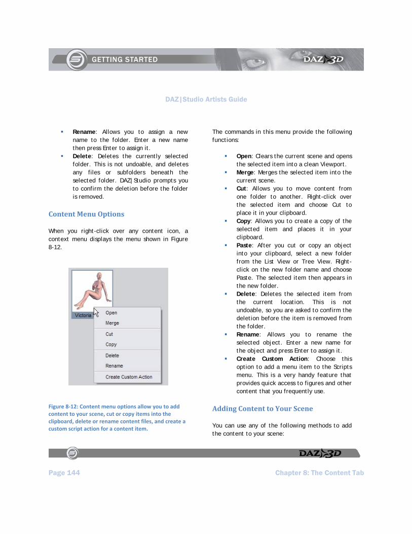
DAZ|Studio Artists Guide
Page 144 Chapter 8: The Content Tab
Rename: Allows you to assign a new name to the folder. Enter a new name then press Enter to assign it.
Delete: Deletes the currently selected folder. This is not undoable, and deletes any files or subfolders beneath the selected folder. DAZ|Studio prompts you to confirm the deletion before the folder is removed.
Content Menu Options
When you right-click over any content icon, a context menu displays the menu shown in Figure 8-12.
Figure 8‐12: Content menu options allow you to add content to your scene, cut or copy items into the clipboard, delete or rename content files, and create a custom script action for a content item.
The commands in this menu provide the following functions:
Open: Clears the current scene and opens the selected item into a clean Viewport.
Merge: Merges the selected item into the current scene.
Cut: Allows you to move content from one folder to another. Right-click over the selected item and choose Cut to place it in your clipboard.
Copy: Allows you to create a copy of the selected item and places it in your clipboard.
Paste: After you cut or copy an object into your clipboard, select a new folder from the List View or Tree View. Right-click on the new folder name and choose Paste. The selected item then appears in the new folder.
Delete: Deletes the selected item from the current location. This is not undoable, so you are asked to confirm the deletion before the item is removed from the folder.
Rename: Allows you to rename the selected object. Enter a new name for the object and press Enter to assign it.
Create Custom Action: Choose this option to add a menu item to the Scripts menu. This is a very handy feature that provides quick access to figures and other content that you frequently use.
Adding Content to Your Scene
You can use any of the following methods to add the content to your scene:
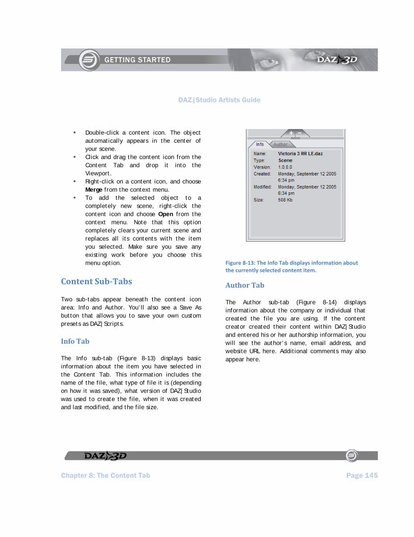
DAZ|Studio Artists Guide
Chapter 8: The Content Tab Page 145
Double-click a content icon. The object automatically appears in the center of your scene.
Click and drag the content icon from the Content Tab and drop it into the Viewport.
Right-click on a content icon, and choose Merge from the context menu.
To add the selected object to a completely new scene, right-click the content icon and choose Open from the context menu. Note that this option completely clears your current scene and replaces all its contents with the item you selected. Make sure you save any existing work before you choose this menu option.
Content SubTabs
Two sub-tabs appear beneath the content icon area: Info and Author. You’ll also see a Save As button that allows you to save your own custom presets as DAZ|Scripts.
Info Tab
The Info sub-tab (Figure 8-13) displays basic information about the item you have selected in the Content Tab. This information includes the name of the file, what type of file it is (depending on how it was saved), what version of DAZ|Studio was used to create the file, when it was created and last modified, and the file size.
Figure 8‐13: The Info Tab displays information about the currently selected content item.
Author Tab
The Author sub-tab (Figure 8-14) displays information about the company or individual that created the file you are using. If the content creator created their content within DAZ|Studio and entered his or her authorship information, you will see the author’s name, email address, and website URL here. Additional comments may also appear here.
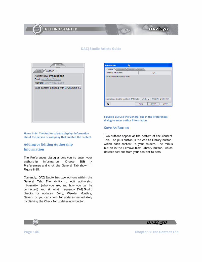
DAZ|Studio Artists Guide
Page 146 Chapter 8: The Content Tab
Figure 8‐14: The Author sub‐tab displays information about the person or company that created the content.
Adding or Editing Authorship Information
The Preferences dialog allows you to enter your authorship information. Choose Edit > Preferences and click the General Tab shown in Figure 8-15.
Currently, DAZ|Studio has two options within the General Tab: The ability to edit authorship information (who you are, and how you can be contacted) and at what frequency DAZ|Studio checks for updates (Daily, Weekly, Monthly, Never), or you can check for updates immediately by clicking the Check for updates now button.
Figure 8‐15: Use the General Tab in the Preferences dialog to enter author information.
Save As Button
Two buttons appear at the bottom of the Content Tab. The plus button is the Add to Library button, which adds content to your folders. The minus button is the Remove from Library button, which deletes content from your content folders.

DAZ|Studio Artists Guide
Chapter 8: The Content Tab Page 147
Figure 8‐16: Buttons at the bottom of the Content Tab allow you to add and remove content from your library.
You can save an entire scene, or you can save specific elements of your scene as a DAZ|Studio preset script file. The steps are as follows:
1. You may want to configure your desired Save Filter preferences set in Edit > Preferences.
2. Click the Add to Library button to open a menu with the following options:
Scene: Selecting Scene saves your entire scene and all objects and settings therein (figures, poses, lights, materials, cameras, props, etc.).
D-Form Preset: Saves the current D-Former to your content folder.
Puppeteer Preset: Saves the current Puppeteer pose animation to your content folder.
Pose Preset: Selecting Pose Preset saves the currently selected figure’s pose information (transformation and/or morph settings, depending on your previously selected preferences).
Shader Preset: Saves the current shader to your content folder.
Materials Preset: Selecting Material Preset saves all material settings (maps, colors, etc.) from the currently selected figure or prop.
Light(s) Preset: Selecting Light(s) Preset saves either the currently selected light(s) or all lights in your scene, depending on your previously selected preferences.
Camera(s) Preset: Selecting Camera(s) Preset saves either the currently selected light(s) or all lights in your scene, depending on your previously selected preferences.
3. You are then asked where you wish to save the scene or preset, and what name you wish to give it. Then, the Filtered Save dialog box appears. This box is functionally identical to its corresponding dialog in the Preferences window. You may navigate folders, create a new folder, name your preset, etc. Make your selections and click OK to finish saving the preset.
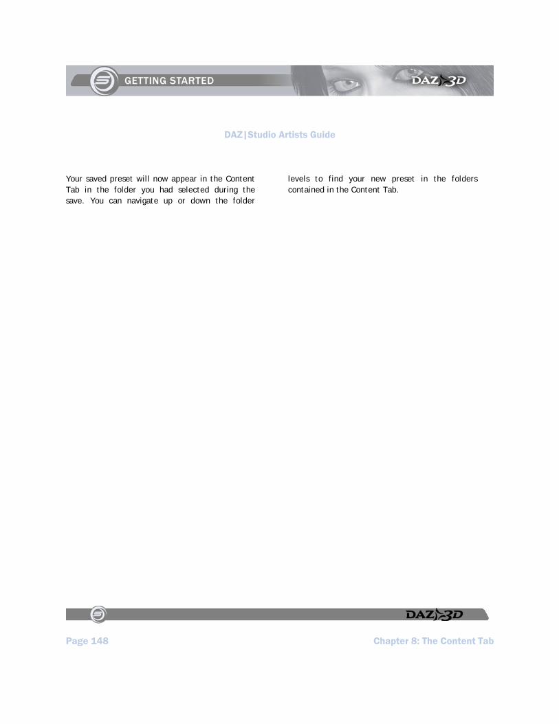
DAZ|Studio Artists Guide
Page 148 Chapter 8: The Content Tab
Your saved preset will now appear in the Content Tab in the folder you had selected during the save. You can navigate up or down the folder
levels to find your new preset in the folders contained in the Content Tab.
DAZ|Studio Artists Guide
Chapter 9: Viewports and Cameras Page 149
Chapter 9 : Viewports and Cameras
Viewports are your window to the virtual universe inside DAZ|Studio. A viewport allows you to see and work with your scene, and DAZ|Studio allows you to look at and make changes to your scene through up to four cameras at once, each in a different viewport. You can customize viewports in a number of ways, as you’ll learn in this chapter.
However, before we start, it might help to explain some basic terminology about 3D, so that you can learn how to find your way around the viewports.
Basic 3D Terminology
If you’re new to 3D graphics, you should familiarize yourself with some basic 3D concepts. Don’t worry, it’s not hard to get around it. Knowing the concepts behind what you’re doing will give you a more complete understanding of how DAZ|Studio works and how to use it.
Axes: Working with 3D on a 2D Screen
DAZ|Studio allows you to work in three dimensions. However, this creates a dilemma … the viewing surface of your computer monitor is two-dimensional, and your mouse only moves on a two-dimensional plane. The images that you generate from DAZ|Studio will all be two-dimensional. If your tools and output are all in 2D, how can you possibly work in 3D?
Each of the three dimensions are represented by axes, with each individual representation termed an axis. These axes are usually designated as shown in Figure 9-1, assuming that you are looking through the default or front camera:
The axis that runs from left to right (width) is known as the X axis. The X axis is shown as red in the figure that follows, and also displays as red when you are using manipulators in DAZ|Studio.
The axis that runs up and down (height) is known as the Y axis. The Y axis is shown as green in the figure that follows, and also displays as green when you are using manipulators in DAZ|Studio.
The axis that runs front to back (depth) is known as the Z axis. The Z axis is shown as blue in the figure that follows, and also displays as blue when you are using manipulators in DAZ|Studio.

DAZ|Studio Artists Guide
Page 150 Chapter 9: Viewports and Cameras
Figure 9‐1: DAZ|Studio uses three axes to determine width (X), height (Y) and depth (Z).
Orthogonal and Perspective Views or Cameras
DAZ|Studio has several pre-built cameras that allow you to view your scene from one or more different directions. You’ll find them in the View Selector menu in the top-left corner of your Viewport area, as shown in Figure 9-2. Click the name of the current viewport to open the view selection menu, and select a different view as needed. These cameras fall into one of two category types: orthogonal or perspective.
Figure 9‐2: DAZ|Studio comes with several preset cameras that you can use as you develop your scenes.
Orthogonal Cameras
Orthogonal views and cameras (highlighted in Figure 9-3) allow you to view your scene with a “straight-on” view. The objects in your scene that are farther away will appear to be the same size as objects that are closer to you. These views are very handy for positioning objects in relation to one another, so that you can get an accurate reflection of their actual position in a scene.

DAZ|Studio Artists Guide
Chapter 9: Viewports and Cameras Page 151
Figure 9‐3: Orthogonal cameras provide a “straight‐on” view of the objects in your scene.
There are six possible orthogonal views for any real or virtual object, and they are listed in the following order in the View selector menu: Front View, Left View, Right View, Back View, Top View, or Bottom View:
The Front View and Back View cameras display the objects in your scene along the X and Y axes.
The Left View and Right View cameras display the objects in your scene along the Y and Z axes.
The Top View and Bottom View cameras display the objects in your scene along the X and Z axes.
Many 3D objects, including humans, are not fully symmetrical, and you may need to view them from several orthographic directions to manipulate them. The view you select depends on what you want to change. For example consider the following while viewing Figure 9-4:
You can use the Front, Back, Left, or Right camera to adjust the height (or Y dimension) of an object, or to move the object
You can use the Front, Back, Top, or Bottom camera to adjust the width (or X dimension) of an object or to move your object to the right or left of the screen.
You can use the Left, Right, Top, or Bottom camera to move a figure forward or backward in your scene (along the Z axis).
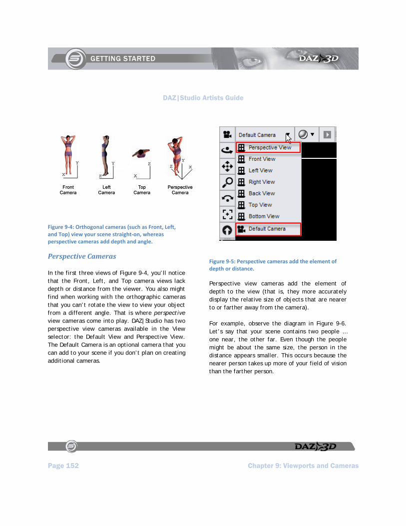
DAZ|Studio Artists Guide
Page 152 Chapter 9: Viewports and Cameras
Figure 9‐4: Orthogonal cameras (such as Front, Left, and Top) view your scene straight‐on, whereas perspective cameras add depth and angle.
Perspective Cameras
In the first three views of Figure 9-4, you’ll notice that the Front, Left, and Top camera views lack depth or distance from the viewer. You also might find when working with the orthographic cameras that you can’t rotate the view to view your object from a different angle. That is where perspective view cameras come into play. DAZ|Studio has two perspective view cameras available in the View selector: the Default View and Perspective View. The Default Camera is an optional camera that you can add to your scene if you don’t plan on creating additional cameras.
Figure 9‐5: Perspective cameras add the element of depth or distance.
Perspective view cameras add the element of depth to the view (that is, they more accurately display the relative size of objects that are nearer to or farther away from the camera).
For example, observe the diagram in Figure 9-6. Let’s say that your scene contains two people … one near, the other far. Even though the people might be about the same size, the person in the distance appears smaller. This occurs because the nearer person takes up more of your field of vision than the farther person.

DAZ|Studio Artists Guide
Chapter 9: Viewports and Cameras Page 153
Figure 9‐6: Objects that are closer to a perspective camera appear larger, and objects that are farther away appear smaller.
Customizing Your Viewport Layout
When you start DAZ|Studio for the first time, you see your scene through one camera. This is called the Single View. The camera you view your scene from is selected from the View Selector menu (Figure 9-7), located at the upper-left corner of the viewport screen.
Figure 9‐7: Use the Viewport Selector to select the camera that you look through.
TIP!
The size of the panes on the left and right of your viewport affects the amount of space that is available for your viewports. If you prefer to work with multiple viewports, reduce the width of the panes, or use floating panes instead. If you use multiple monitors, you can also move your panes to a second monitor so that the viewports use the maximum amount of screen real estate.
However, as we have mentioned, you can also configure DAZ|Studio to look through more than one camera at a time. When you make changes in one viewport, the changes are automatically updated in the other viewports that you display.
To view your scene through more than one viewport, choose View > Viewport Layout, and choose the layout arrangement that you want to use from the options shown in Figure 9-8. There are several options:

DAZ|Studio Artists Guide
Page 154 Chapter 9: Viewports and Cameras
Figure 9‐8: View your scene with anywhere from one to four viewports at a time.
Single View: Displays the currently selected view in the entire Viewport screen. This is the view that DAZ|Studio starts out with in the default interface layout.
Side by Side: Divides the viewport area into two vertical panels. By default, the Perspective view appears in the left panel, and the Front view appears in the right panel.
Top and Bottom: Divides the viewport area into two horizontal panels. The Perspective view appears in the top panel, and the Front View appears in the bottom panel by default.
Four Views: Divides the viewport area into four equally sized panels, two on top and two on the bottom. Perspective and Front views appear on the top, and Left and Top views appear on the bottom.
2 Right, 1 Left: Divides your viewport into three sections. The left half contains the Perspective view by default. The right half displays the Front and Left views in half-sized windows.
2 Top, 1 Bottom: Divides your viewport into three sections. The top half displays the Perspective and Front views in half-sized windows. The bottom half displays the Left view.
2 Left, 1 Right: Divides your viewport into three sections. The Perspective and Front views are arranged in half-sized windows on the left, and the Left View appears on the right.
2 Bottom, 1 Top: Divides your viewport into three sections. The Perspective view appears at the top, and the Front and Left views appear in half-sized windows on the bottom.
3 Right, 1 Left: Divides your viewport into four sections. The left side displays the Perspective view. The right side displays the Front, Left, and Top views.
3 Top, 1 Bottom: Divides your viewport into four sections. The top section displays the Perspective, Front, and Left views. The bottom section displays the Top view.
3 Left, 1 Right: Divides your viewport into four sections. The left section displays the Perspective, Front, and Left

DAZ|Studio Artists Guide
Chapter 9: Viewports and Cameras Page 155
views. The right section displays the Top view.
3 Bottom, 1 Top: Divides your viewport into four sections. The top section displays the Perspective view, and the bottom portion displays the Front, Left, and Top view.
Figure 9-9 shows examples of the viewport options while displaying a simple scene.
Figure 9‐9: A scene displayed with each of the available viewport options.
Selecting the Active Viewport
If you are working in a multi-viewport layout, you can make changes to your scene within any
available viewport. When you make changes in the active viewport, the other viewports in your multi-viewport layout also change.
To switch your active viewport, use one of the following methods:
Click a blank area in the toolbar that appears above the viewport you want to select.
Click any object in that appears in the viewport you want to select.
Changing Cameras
Whether you display one view or multiple views in your viewport area, you aren’t restricted to using the cameras that appear in those viewports by default. You can select any camera you choose in any of the views, including light cameras or other custom cameras that you create yourself. You’ll learn more about how to create custom cameras later in this chapter.
To switch cameras in a viewport:
1. Select the viewport that you want to assign a camera to.
2. Open the View Selection List drop-down at the upper left of the selected viewport.
3. Select the camera you want to assign to that viewport from the Views list.
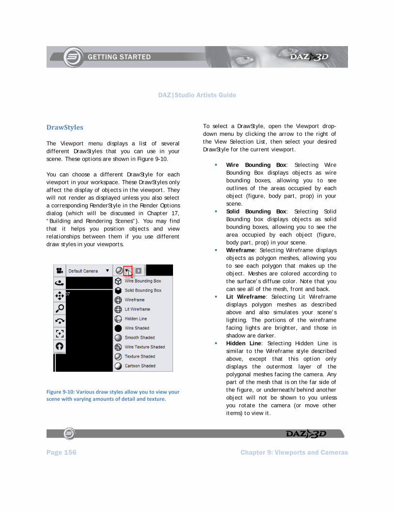
DAZ|Studio Artists Guide
Page 156 Chapter 9: Viewports and Cameras
DrawStyles
The Viewport menu displays a list of several different DrawStyles that you can use in your scene. These options are shown in Figure 9-10.
You can choose a different DrawStyle for each viewport in your workspace. These DrawStyles only affect the display of objects in the viewport. They will not render as displayed unless you also select a corresponding RenderStyle in the Render Options dialog (which will be discussed in Chapter 17, “Building and Rendering Scenes”). You may find that it helps you position objects and view relationships between them if you use different draw styles in your viewports.
Figure 9‐10: Various draw styles allow you to view your scene with varying amounts of detail and texture.
To select a DrawStyle, open the Viewport drop-down menu by clicking the arrow to the right of the View Selection List, then select your desired DrawStyle for the current viewport.
Wire Bounding Box: Selecting Wire Bounding Box displays objects as wire bounding boxes, allowing you to see outlines of the areas occupied by each object (figure, body part, prop) in your scene.
Solid Bounding Box: Selecting Solid Bounding box displays objects as solid bounding boxes, allowing you to see the area occupied by each object (figure, body part, prop) in your scene.
Wireframe: Selecting Wireframe displays objects as polygon meshes, allowing you to see each polygon that makes up the object. Meshes are colored according to the surface’s diffuse color. Note that you can see all of the mesh, front and back.
Lit Wireframe: Selecting Lit Wireframe displays polygon meshes as described above and also simulates your scene’s lighting. The portions of the wireframe facing lights are brighter, and those in shadow are darker.
Hidden Line: Selecting Hidden Line is similar to the Wireframe style described above, except that this option only displays the outermost layer of the polygonal meshes facing the camera. Any part of the mesh that is on the far side of the figure, or underneath/behind another object will not be shown to you unless you rotate the camera (or move other items) to view it.

DAZ|Studio Artists Guide
Chapter 9: Viewports and Cameras Page 157
Wire Shaded: Selecting Wire Shaded displays both the polygonal meshes and object shading. This is a combination of Hidden Line and Smooth Shaded.
Smooth Shaded: Selecting Smooth Shaded shows objects as solids with color and lighting but no maps.
Wire Texture Shaded: Selecting Wire Texture Shaded displays all objects within the scene as a polygonal mesh imposed over the object’s textures.
Texture Shaded: Selecting Texture Shaded shows objects as solids with all color, light, and map information displayed. This is the default setting for DAZ|Studio.
Cartoon Shaded: (Available only with full OpenGL capability.) Cartoon Shaded will give you an accurate preview of what your image will look like after rendering if you have your render options set for Cartoon (as opposed to normal) mode. This gives you the chance to adjust the lighting for accurate shadows. (Note: Macintosh users may not have this option available as a preview, even if the card is capable of OpenGL acceleration.)
Figure 9-11 shows rendered examples of each of the draw styles that are available in DAZ|Studio.
Figure 9‐11: A scene is rendered in each of the available draw styles.
Other Viewport Options
Besides changing the way objects are displayed in your viewport, the Viewport Options dialog also displays the following additional commands that allow you to customize your viewport display:
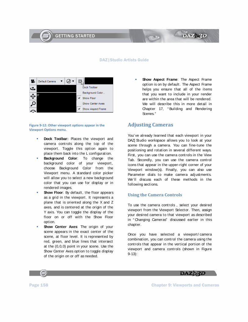
DAZ|Studio Artists Guide
Page 158 Chapter 9: Viewports and Cameras
Figure 9‐12: Other viewport options appear in the Viewport Options menu.
Dock Toolbar: Places the viewport and camera controls along the top of the viewport. Toggle this option again to place them back into the L configuration.
Background Color: To change the background color of your viewport, choose Background Color from the Viewport menu. A standard color picker will allow you to select a new background color that you can use for display or in rendered images.
Show Floor: By default, the floor appears as a grid in the viewport. It represents a plane that is oriented along the X and Z axes, and is centered at the origin of the Y axis. You can toggle the display of the floor on or off with the Show Floor option.
Show Center Axes: The origin of your scene appears in the exact center of the scene, at floor level. It is represented by red, green, and blue lines that intersect at the (0,0,0) point in your scene. Use the Show Center Axes option to toggle display of the origin on or off as needed.
Show Aspect Frame: The Aspect Frame option is on by default. The Aspect Frame helps you ensure that all of the items that you want to include in your render are within the area that will be rendered. We will describe this in more detail in Chapter 17, “Building and Rendering Scenes.”
Adjusting Cameras
You’ve already learned that each viewport in your DAZ|Studio workspace allows you to look at your scene through a camera. You can fine-tune the positioning and rotation in several different ways. First, you can use the camera controls in the View Tab. Secondly, you can use the camera control icons that appear in the upper-right corner of your Viewport window(s). Finally, you can also use Parameter dials to make camera adjustments. We’ll discuss each of these methods in the following sections.
Using the Camera Controls
To use the camera controls , select your desired viewport from the Viewport Selector. Then, assign your desired camera to that viewport as described in “Changing Cameras” discussed earlier in this chapter.
Once you have selected a viewport/camera combination, you can control the camera using the controls that appear in the vertical portion of the viewport and camera controls (shown in Figure 9-13):
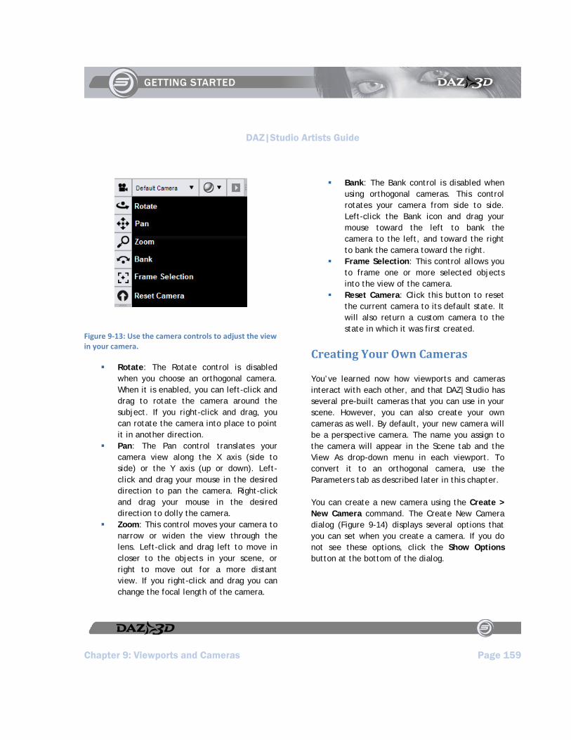
DAZ|Studio Artists Guide
Chapter 9: Viewports and Cameras Page 159
Figure 9‐13: Use the camera controls to adjust the view in your camera.
Rotate: The Rotate control is disabled when you choose an orthogonal camera. When it is enabled, you can left-click and drag to rotate the camera around the subject. If you right-click and drag, you can rotate the camera into place to point it in another direction.
Pan: The Pan control translates your camera view along the X axis (side to side) or the Y axis (up or down). Left-click and drag your mouse in the desired direction to pan the camera. Right-click and drag your mouse in the desired direction to dolly the camera.
Zoom: This control moves your camera to narrow or widen the view through the lens. Left-click and drag left to move in closer to the objects in your scene, or right to move out for a more distant view. If you right-click and drag you can change the focal length of the camera.
Bank: The Bank control is disabled when using orthogonal cameras. This control rotates your camera from side to side. Left-click the Bank icon and drag your mouse toward the left to bank the camera to the left, and toward the right to bank the camera toward the right.
Frame Selection: This control allows you to frame one or more selected objects into the view of the camera.
Reset Camera: Click this button to reset the current camera to its default state. It will also return a custom camera to the state in which it was first created.
Creating Your Own Cameras
You’ve learned now how viewports and cameras interact with each other, and that DAZ|Studio has several pre-built cameras that you can use in your scene. However, you can also create your own cameras as well. By default, your new camera will be a perspective camera. The name you assign to the camera will appear in the Scene tab and the View As drop-down menu in each viewport. To convert it to an orthogonal camera, use the Parameters tab as described later in this chapter.
You can create a new camera using the Create > New Camera command. The Create New Camera dialog (Figure 9-14) displays several options that you can set when you create a camera. If you do not see these options, click the Show Options button at the bottom of the dialog.
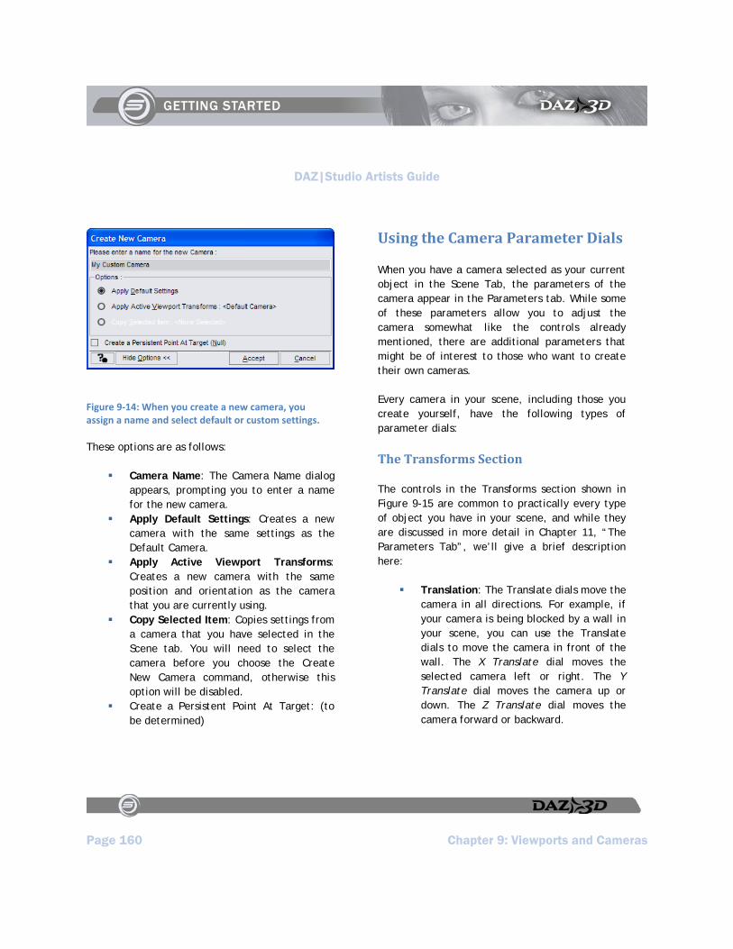
DAZ|Studio Artists Guide
Page 160 Chapter 9: Viewports and Cameras
Figure 9‐14: When you create a new camera, you assign a name and select default or custom settings.
These options are as follows:
Camera Name: The Camera Name dialog appears, prompting you to enter a name for the new camera.
Apply Default Settings: Creates a new camera with the same settings as the Default Camera.
Apply Active Viewport Transforms: Creates a new camera with the same position and orientation as the camera that you are currently using.
Copy Selected Item: Copies settings from a camera that you have selected in the Scene tab. You will need to select the camera before you choose the Create New Camera command, otherwise this option will be disabled.
Create a Persistent Point At Target: (to be determined)
Using the Camera Parameter Dials
When you have a camera selected as your current object in the Scene Tab, the parameters of the camera appear in the Parameters tab. While some of these parameters allow you to adjust the camera somewhat like the controls already mentioned, there are additional parameters that might be of interest to those who want to create their own cameras.
Every camera in your scene, including those you create yourself, have the following types of parameter dials:
The Transforms Section
The controls in the Transforms section shown in Figure 9-15 are common to practically every type of object you have in your scene, and while they are discussed in more detail in Chapter 11, “The Parameters Tab”, we’ll give a brief description here:
Translation: The Translate dials move the camera in all directions. For example, if your camera is being blocked by a wall in your scene, you can use the Translate dials to move the camera in front of the wall. The X Translate dial moves the selected camera left or right. The Y Translate dial moves the camera up or down. The Z Translate dial moves the camera forward or backward.

DAZ|Studio Artists Guide
Chapter 9: Viewports and Cameras Page 161
Figure 9‐15: Transforms allow you to move, rotate, or scale the camera.
Rotation: The Rotation dials rotate the camera in all directions. To explain, think of yourself holding a camera and pointing it upward to photograph the top of a building. However, note that on the surface, it doesn’t seem to follow the “norm” about how the X, Y, and Z axes work. We’ll explain why rotation works this way in Chapter 11, but for now we will just list what the dials do. The X Rotate dial points the camera upward or
downward. The Y Rotate dial points the camera to the left or right. The Z Rotate dial tilts (or banks) the camera to the left or right.
Scale: The Scale sliders change the physical size of the camera object in your scene. They do not affect the way the camera displays your scene in any way. The Scale slider scales the camera equally in all directions. The X Scale slider adjusts the width of the camera geometry. The Y Scale slider adjusts the height of the camera geometry (in other words, it makes the camera longer or shorter). The Z Scale slider adjusts the depth of the camera geometry.
The Misc Section
The Miscellaneous section of the Parameters tab (Figure 9-16) also contains controls that are common to many objects in your scene. There are three options here: Visible, Selectable, and Point At.
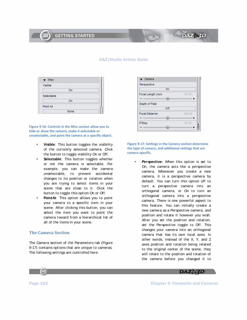
DAZ|Studio Artists Guide
Page 162 Chapter 9: Viewports and Cameras
Figure 9‐16: Controls in the Misc section allow you to hide or show the camera, make it selectable or unselectable, and point the camera at a specific object.
Visible: This button toggles the visibility of the currently selected camera. Click the button to toggle visibility On or Off.
Selectable: This button toggles whether or not the camera is selectable. For example, you can make the camera unselectable, to prevent accidental changes to its position or rotation when you are trying to select items in your scene that are close to it. Click the button to toggle this option On or Off.
PointAt: This option allows you to point your camera to a specific item in your scene. After clicking this button, you can select the item you want to point the camera toward from a hierarchical list of all of the items in your scene.
The Camera Section
The Camera section of the Parameters tab (Figure 9-17) contains options that are unique to cameras. The following settings are controlled here:
Figure 9‐17: Settings in the Camera section determine the type of camera, and additional settings that are camera specific.
Perspective: When this option is set to On, the camera acts like a perspective camera. Whenever you create a new camera, it is a perspective camera by default. You can turn this option off to turn a perspective camera into an orthogonal camera, or On to turn an orthogonal camera into a perspective camera. There is one powerful aspect to this feature. You can initially create a new camera as a Perspective camera, and position and rotate it however you wish. After you set the position and rotation, set the Perspective toggle to Off. This changes your camera into an orthogonal camera that has its own local axes. In other words, instead of the X, Y, and Z axes position and rotation being related to the original center of the scene, they will relate to the position and rotation of the camera before you changed it to
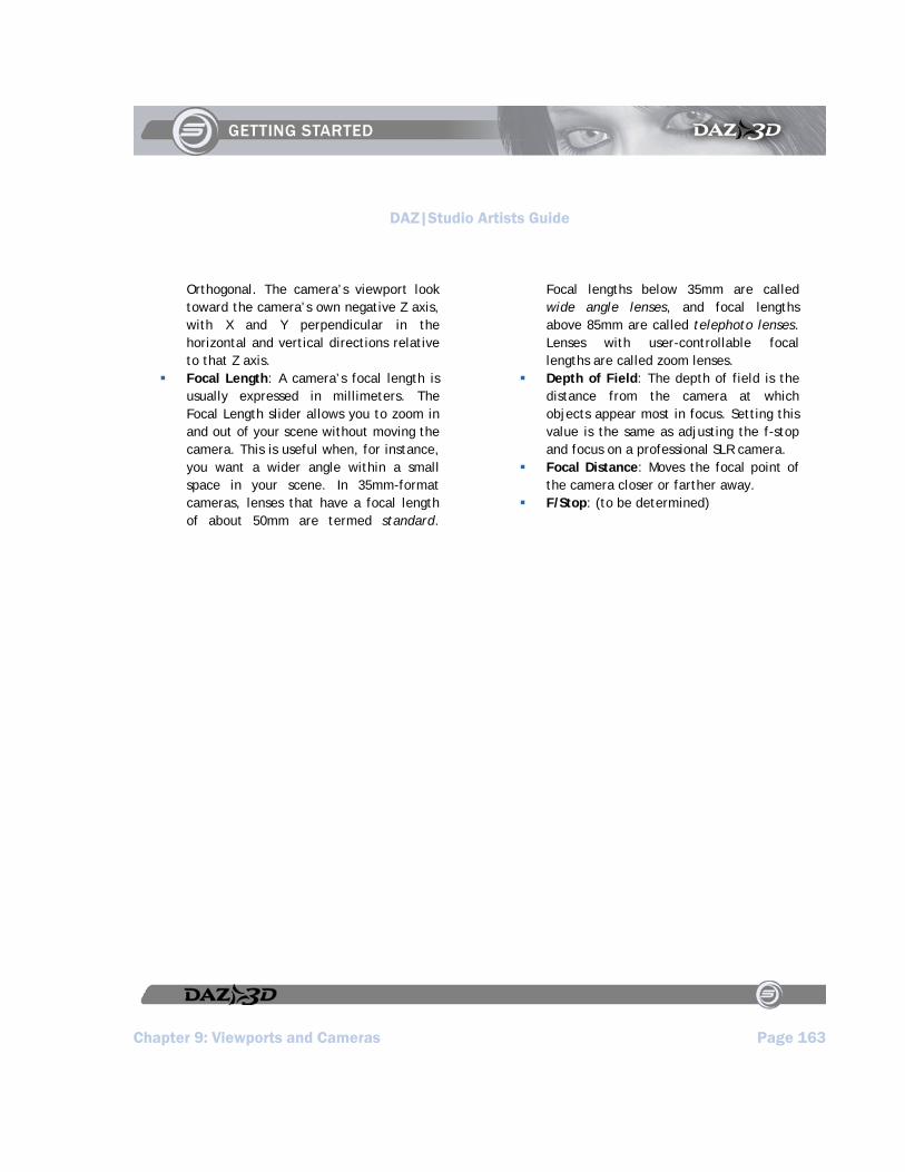
DAZ|Studio Artists Guide
Chapter 9: Viewports and Cameras Page 163
Orthogonal. The camera’s viewport look toward the camera’s own negative Z axis, with X and Y perpendicular in the horizontal and vertical directions relative to that Z axis.
Focal Length: A camera’s focal length is usually expressed in millimeters. The Focal Length slider allows you to zoom in and out of your scene without moving the camera. This is useful when, for instance, you want a wider angle within a small space in your scene. In 35mm-format cameras, lenses that have a focal length of about 50mm are termed standard.
Focal lengths below 35mm are called wide angle lenses, and focal lengths above 85mm are called telephoto lenses. Lenses with user-controllable focal lengths are called zoom lenses.
Depth of Field: The depth of field is the distance from the camera at which objects appear most in focus. Setting this value is the same as adjusting the f-stop and focus on a professional SLR camera.
Focal Distance: Moves the focal point of the camera closer or farther away.
F/Stop: (to be determined)

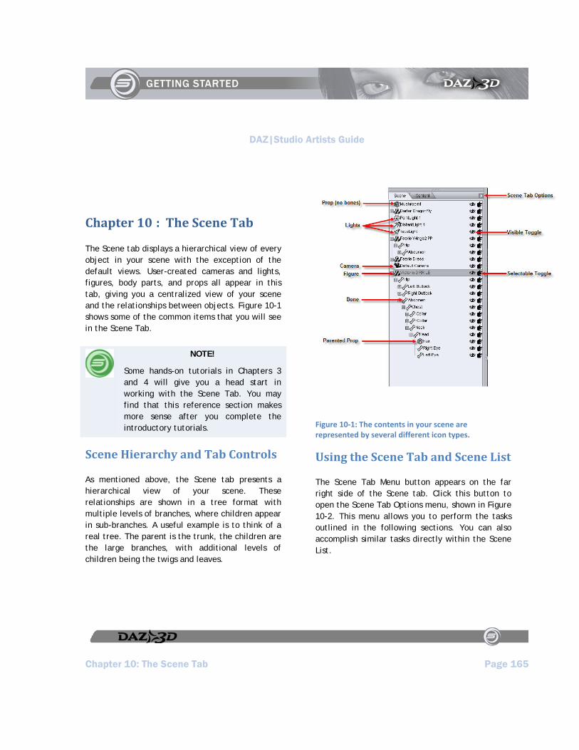
DAZ|Studio Artists Guide
Chapter 10: The Scene Tab Page 165
Chapter 10 : The Scene Tab
The Scene tab displays a hierarchical view of every object in your scene with the exception of the default views. User-created cameras and lights, figures, body parts, and props all appear in this tab, giving you a centralized view of your scene and the relationships between objects. Figure 10-1 shows some of the common items that you will see in the Scene Tab.
NOTE!
Some hands-on tutorials in Chapters 3 and 4 will give you a head start in working with the Scene Tab. You may find that this reference section makes more sense after you complete the introductory tutorials.
Scene Hierarchy and Tab Controls
As mentioned above, the Scene tab presents a hierarchical view of your scene. These relationships are shown in a tree format with multiple levels of branches, where children appear in sub-branches. A useful example is to think of a real tree. The parent is the trunk, the children are the large branches, with additional levels of children being the twigs and leaves.
Figure 10‐1: The contents in your scene are represented by several different icon types.
Using the Scene Tab and Scene List
The Scene Tab Menu button appears on the far right side of the Scene tab. Click this button to open the Scene Tab Options menu, shown in Figure 10-2. This menu allows you to perform the tasks outlined in the following sections. You can also accomplish similar tasks directly within the Scene List.
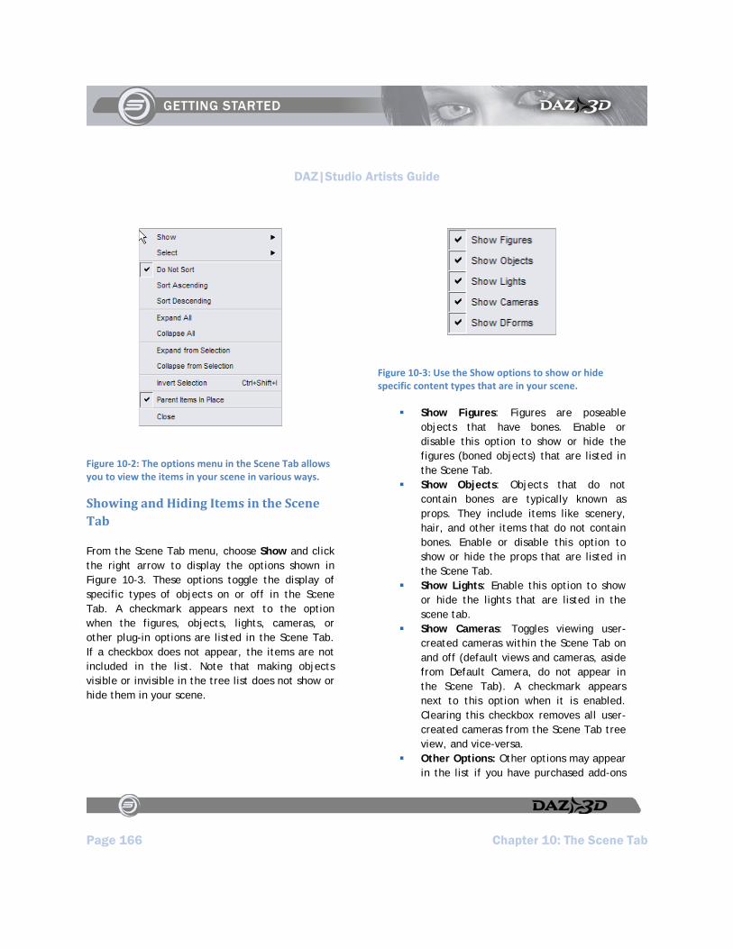
DAZ|Studio Artists Guide
Page 166 Chapter 10: The Scene Tab
Figure 10‐2: The options menu in the Scene Tab allows you to view the items in your scene in various ways.
Showing and Hiding Items in the Scene Tab
From the Scene Tab menu, choose Show and click the right arrow to display the options shown in Figure 10-3. These options toggle the display of specific types of objects on or off in the Scene Tab. A checkmark appears next to the option when the figures, objects, lights, cameras, or other plug-in options are listed in the Scene Tab. If a checkbox does not appear, the items are not included in the list. Note that making objects visible or invisible in the tree list does not show or hide them in your scene.
Figure 10‐3: Use the Show options to show or hide specific content types that are in your scene.
Show Figures: Figures are poseable objects that have bones. Enable or disable this option to show or hide the figures (boned objects) that are listed in the Scene Tab.
Show Objects: Objects that do not contain bones are typically known as props. They include items like scenery, hair, and other items that do not contain bones. Enable or disable this option to show or hide the props that are listed in the Scene Tab.
Show Lights: Enable this option to show or hide the lights that are listed in the scene tab.
Show Cameras: Toggles viewing user-created cameras within the Scene Tab on and off (default views and cameras, aside from Default Camera, do not appear in the Scene Tab). A checkmark appears next to this option when it is enabled. Clearing this checkbox removes all user-created cameras from the Scene Tab tree view, and vice-versa.
Other Options: Other options may appear in the list if you have purchased add-ons
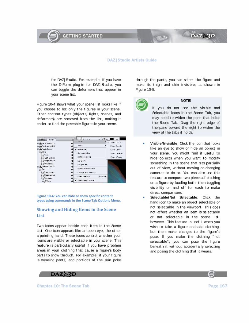
DAZ|Studio Artists Guide
Chapter 10: The Scene Tab Page 167
for DAZ|Studio. For example, if you have the D-Form plug-in for DAZ|Studio, you can toggle the deformers that appear in your scene list.
Figure 10-4 shows what your scene list looks like if you choose to list only the figures in your scene. Other content types (objects, lights, scenes, and deformers) are removed from the list, making it easier to find the poseable figures in your scene.
Figure 10‐4: You can hide or show specific content types using commands in the Scene Tab Options Menu.
Showing and Hiding Items in the Scene List
Two icons appear beside each item in the Scene List. One icon appears like an open eye, the other a pointing hand. These icons control whether your items are visible or selectable in your scene. This feature is particularly useful if you have problem areas in your clothing that cause a figure's body parts to show through. For example, if your figure is wearing pants, and portions of the skin poke
through the pants, you can select the figure and make its thigh and shin invisible, as shown in Figure 10-5.
NOTE!
If you do not see the Visible and Selectable icons in the Scene Tab, you may need to widen the pane that holds the Scene Tab. Drag the right edge of the pane toward the right to widen the view of the tabs it holds.
Visible/Invisible: Click the icon that looks like an eye to show or hide an object in your scene. You might find it useful to hide objects when you want to modify something in the scene that sits partially out of view, without moving or changing cameras to do so. You can also use this feature to compare two pieces of clothing on a figure by loading both, then toggling visibility on and off for each to make direct comparisons.
Selectable/Not Selectable: Click the hand icon to make an object selectable or not selectable in the viewport. This does not affect whether an item is selectable or not selectable in the scene list, however. This feature is useful when you wish to take a figure and add clothing, but then make changes to the figure’s pose. If you make the clothing “not selectable”, you can pose the figure beneath it without accidentally selecting and posing the clothing that it wears.
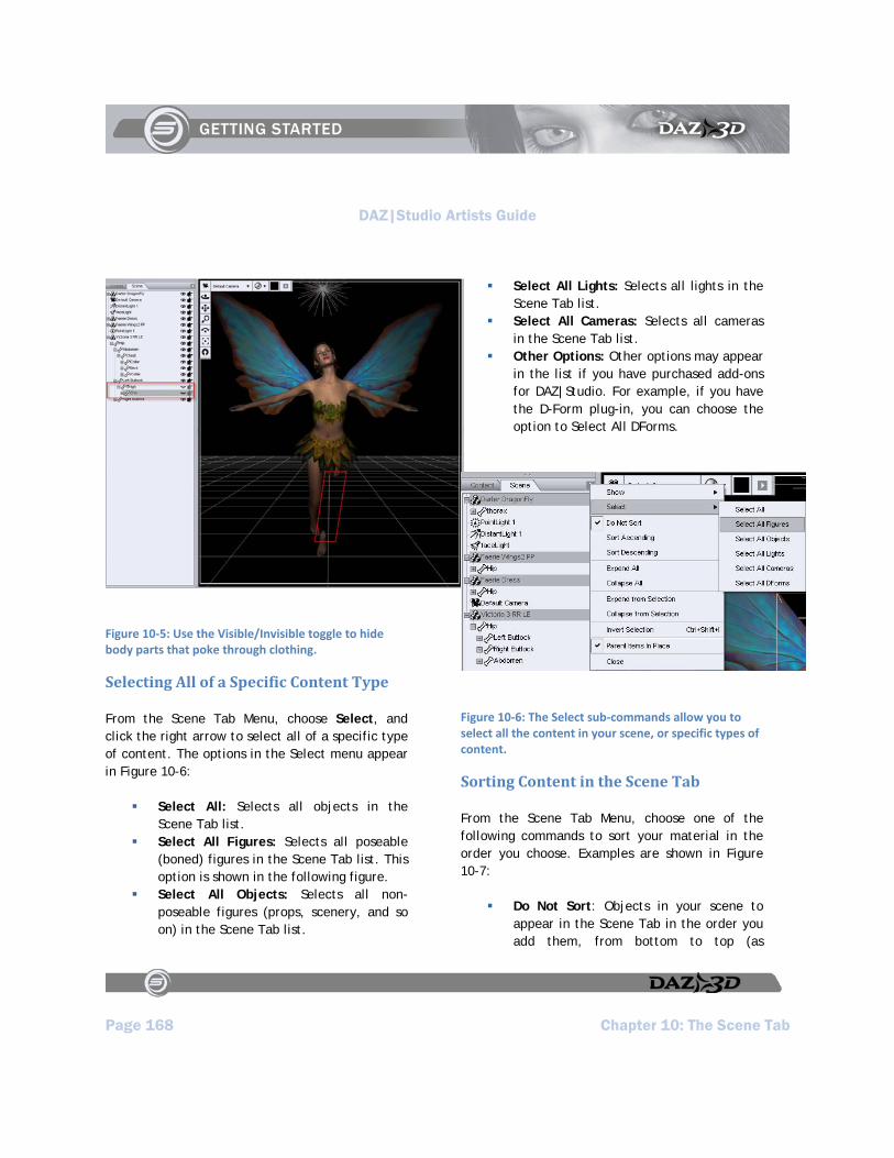
DAZ|Studio Artists Guide
Page 168 Chapter 10: The Scene Tab
Figure 10‐5: Use the Visible/Invisible toggle to hide body parts that poke through clothing.
Selecting All of a Specific Content Type
From the Scene Tab Menu, choose Select, and click the right arrow to select all of a specific type of content. The options in the Select menu appear in Figure 10-6:
Select All: Selects all objects in the Scene Tab list.
Select All Figures: Selects all poseable (boned) figures in the Scene Tab list. This option is shown in the following figure.
Select All Objects: Selects all non-poseable figures (props, scenery, and so on) in the Scene Tab list.
Select All Lights: Selects all lights in the Scene Tab list.
Select All Cameras: Selects all cameras in the Scene Tab list.
Other Options: Other options may appear in the list if you have purchased add-ons for DAZ|Studio. For example, if you have the D-Form plug-in, you can choose the option to Select All DForms.
Figure 10‐6: The Select sub‐commands allow you to select all the content in your scene, or specific types of content.
Sorting Content in the Scene Tab
From the Scene Tab Menu, choose one of the following commands to sort your material in the order you choose. Examples are shown in Figure 10-7:
Do Not Sort: Objects in your scene to appear in the Scene Tab in the order you add them, from bottom to top (as

DAZ|Studio Artists Guide
Chapter 10: The Scene Tab Page 169
explained in the Tutorials section.) This is the default behavior of the Scene Tab.
Sort Ascending: Causes objects in your scene to appear in the Scene Tab sorted by name in ascending (A-Z) order.
Sort Descending: Causes objects in your scene to appear in the Scene Tab sorted by name in descending (Z-A) order.
Figure 10‐7: You can choose to not sort the items in your scene, or sort by ascending or descending alphabetical order.
Expanding and Collapsing the Entire Tree
You can completely expand or collapse the scene list using the following commands in the Scene Tab Menu. Figure 10-8 shows how these options affect the display of the items in the Scene Tab.
Expand All: Expands all branches and sub-branches in your scene.
Collapse All: Collapses all branches and sub-branches in your scene.
Figure 10‐8: Use the Expand All or Collapse All commands to fully expand or collapse the scene list.
Expanding and Collapsing Portions of the Tree
For ease of viewing, you can expand and collapse individual branches and sub-branches in the Scene List tree:
To expand a collapsed branch, either click the + (plus sign) button next to the branch you wish to expand or double-click
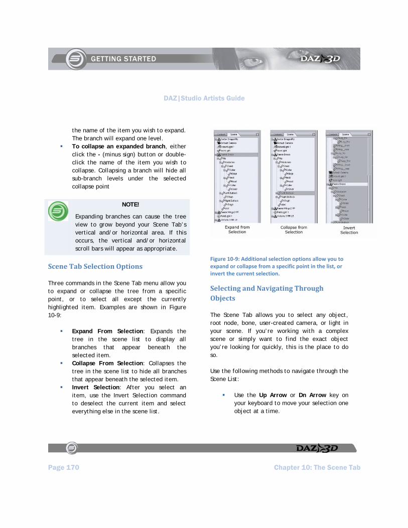
DAZ|Studio Artists Guide
Page 170 Chapter 10: The Scene Tab
the name of the item you wish to expand. The branch will expand one level.
To collapse an expanded branch, either click the - (minus sign) button or double-click the name of the item you wish to collapse. Collapsing a branch will hide all sub-branch levels under the selected collapse point
NOTE!
Expanding branches can cause the tree view to grow beyond your Scene Tab’s vertical and/or horizontal area. If this occurs, the vertical and/or horizontal scroll bars will appear as appropriate.
Scene Tab Selection Options
Three commands in the Scene Tab menu allow you to expand or collapse the tree from a specific point, or to select all except the currently highlighted item. Examples are shown in Figure 10-9:
Expand From Selection: Expands the tree in the scene list to display all branches that appear beneath the selected item.
Collapse From Selection: Collapses the tree in the scene list to hide all branches that appear beneath the selected item.
Invert Selection: After you select an item, use the Invert Selection command to deselect the current item and select everything else in the scene list.
Figure 10‐9: Additional selection options allow you to expand or collapse from a specific point in the list, or invert the current selection.
Selecting and Navigating Through Objects
The Scene Tab allows you to select any object, root node, bone, user-created camera, or light in your scene. If you’re working with a complex scene or simply want to find the exact object you’re looking for quickly, this is the place to do so.
Use the following methods to navigate through the Scene List:
Use the Up Arrow or Dn Arrow key on your keyboard to move your selection one object at a time.
DAZ|Studio Artists Guide
Chapter 10: The Scene Tab Page 171
Use the PgUp and PgDn keys on your keyboard to scroll quickly through the scene list.
Use the Left Arrow and Right Arrow keys to expand, collapse, and navigate tree levels.
The following procedures allow you to select one or more items in the Scene List:
To select a single object in your scene, use the Scene Tab’s tree view to locate your desired object, then click it. This is very useful in a complex scene or where you cannot readily see your desired object using the viewports.
To select multiple objects using the Scene Tab, you may use any combination of the following methods:
Click and drag around a group of nodes inside the hierarchy view. Children of selected objects are also selected, whether or not their branches are expanded.
Press Shift while clicking to select all nodes between your previous selection and your next click.
Press Ctrl while clicking to make multiple individual selections.
Creating Parent/Child Relationships
DAZ|Studio supports drag-and-drop parenting, or the creation of hierarchical parent/child relationships between items. Child nodes appear on sub-branches within the Scene tab’s tree view.
To parent one object to another:
1. Make sure that both the parent and child objects are in your scene. Don’t worry about positioning the child object just yet.
2. In the Scene Tab, click and drag the child object under your desired parent object. You can parent any object to any other object or bone. For example, you can parent a baseball bat to a hand, a ring to a finger.
3. The child object will move so that:
Its local origin coincides with the parent object’s origin.
Its local axes are aligned with the parent object’s local axes.
4. Rotate and/or translate the child object into your desired position relative to the parent.
5. Child objects retain their position and alignment relative to any parent object. For example, if you parent a baseball bat to Michael’s hand and then make the same bat a child of Victoria’s hand, the bat will move so as to retain the same position relative to Victoria’s hand (distance and alignment) that it had with Michael’s hand.
Parenting Items in Place
As mentioned in the previous section, a parented item attaches itself in relation to the origin and axes of the item that it is parented to. The Parent Items in Place command in the Scene Tab options
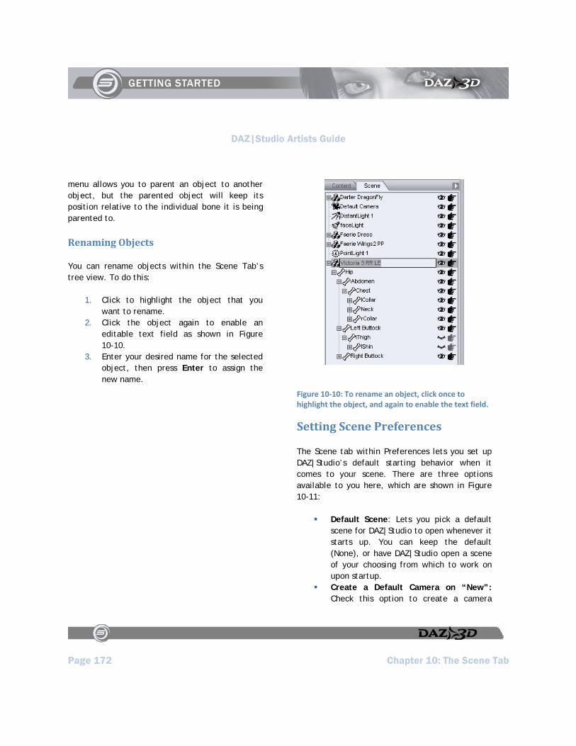
DAZ|Studio Artists Guide
Page 172 Chapter 10: The Scene Tab
menu allows you to parent an object to another object, but the parented object will keep its position relative to the individual bone it is being parented to.
Renaming Objects
You can rename objects within the Scene Tab’s tree view. To do this:
1. Click to highlight the object that you want to rename.
2. Click the object again to enable an editable text field as shown in Figure 10-10.
3. Enter your desired name for the selected object, then press Enter to assign the new name.
Figure 10‐10: To rename an object, click once to highlight the object, and again to enable the text field.
Setting Scene Preferences
The Scene tab within Preferences lets you set up DAZ|Studio’s default starting behavior when it comes to your scene. There are three options available to you here, which are shown in Figure 10-11:
Default Scene: Lets you pick a default scene for DAZ|Studio to open whenever it starts up. You can keep the default (None), or have DAZ|Studio open a scene of your choosing from which to work on upon startup.
Create a Default Camera on “New”: Check this option to create a camera
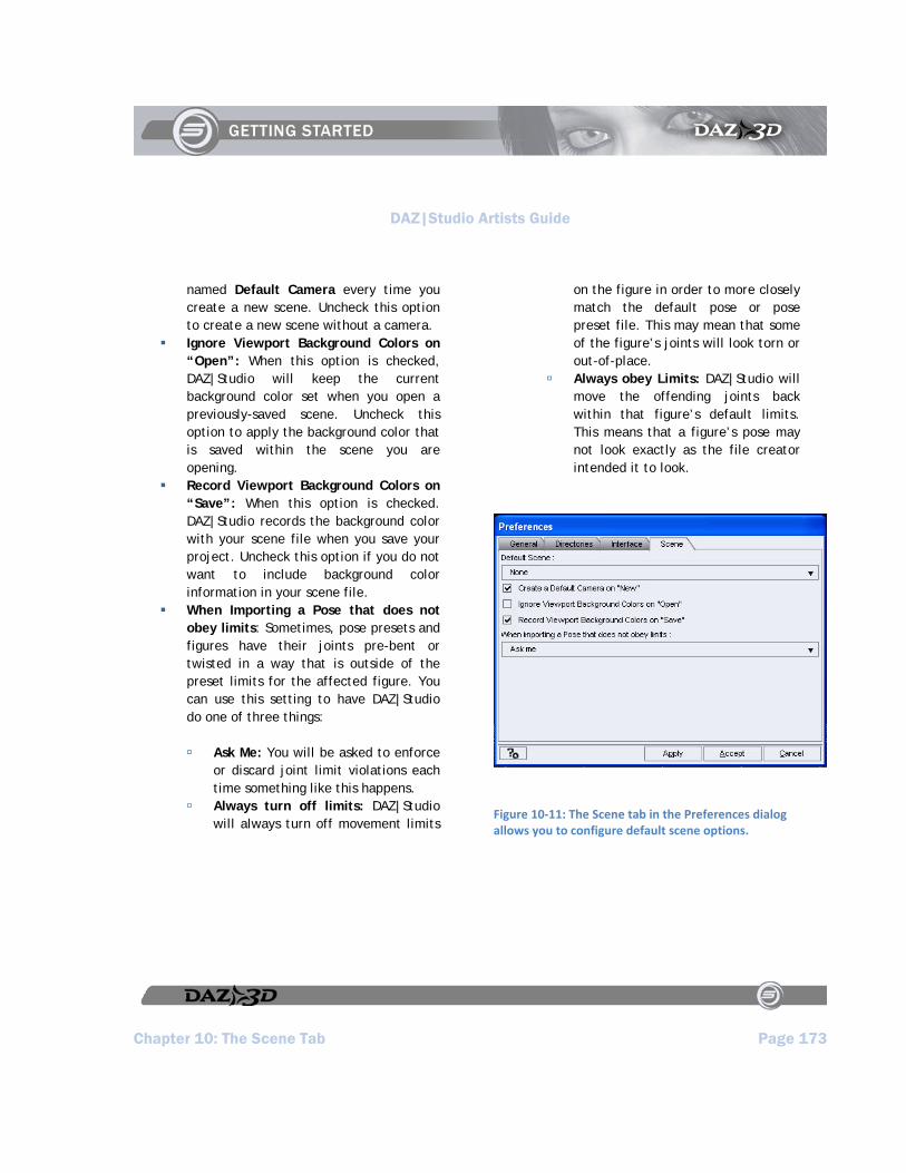
DAZ|Studio Artists Guide
Chapter 10: The Scene Tab Page 173
named Default Camera every time you create a new scene. Uncheck this option to create a new scene without a camera.
Ignore Viewport Background Colors on “Open”: When this option is checked, DAZ|Studio will keep the current background color set when you open a previously-saved scene. Uncheck this option to apply the background color that is saved within the scene you are opening.
Record Viewport Background Colors on “Save”: When this option is checked. DAZ|Studio records the background color with your scene file when you save your project. Uncheck this option if you do not want to include background color information in your scene file.
When Importing a Pose that does not obey limits: Sometimes, pose presets and figures have their joints pre-bent or twisted in a way that is outside of the preset limits for the affected figure. You can use this setting to have DAZ|Studio do one of three things:
Ask Me: You will be asked to enforce or discard joint limit violations each time something like this happens.
Always turn off limits: DAZ|Studio will always turn off movement limits
on the figure in order to more closely match the default pose or pose preset file. This may mean that some of the figure’s joints will look torn or out-of-place.
Always obey Limits: DAZ|Studio will move the offending joints back within that figure’s default limits. This means that a figure’s pose may not look exactly as the file creator intended it to look.
Figure 10‐11: The Scene tab in the Preferences dialog allows you to configure default scene options.

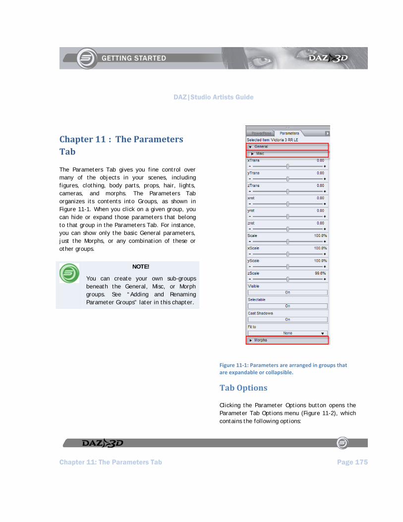
DAZ|Studio Artists Guide
Chapter 11: The Parameters Tab Page 175
Chapter 11 : The Parameters Tab
The Parameters Tab gives you fine control over many of the objects in your scenes, including figures, clothing, body parts, props, hair, lights, cameras, and morphs. The Parameters Tab organizes its contents into Groups, as shown in Figure 11-1. When you click on a given group, you can hide or expand those parameters that belong to that group in the Parameters Tab. For instance, you can show only the basic General parameters, just the Morphs, or any combination of these or other groups.
NOTE!
You can create your own sub-groups beneath the General, Misc, or Morph groups. See “Adding and Renaming Parameter Groups” later in this chapter.
Figure 11‐1: Parameters are arranged in groups that are expandable or collapsible.
Tab Options
Clicking the Parameter Options button opens the Parameter Tab Options menu (Figure 11-2), which contains the following options:

DAZ|Studio Artists Guide
Page 176 Chapter 11: The Parameters Tab
Figure 11‐2: The Options menu in the Parameters Tab contains commands that help you memorize and restore settings, along with other commands that pose or position your figures.
Memorize: Opens a submenu of options that allow temporary storage of selected parameter settings. You can memorize the state of an entire figure, a pose, morphs, selected items, or transforms (position).
Restore: The complement menu for Memorize. The Restore options allow you to recall the settings you have previously memorized.
Zero: Allows you to set all dial settings to Zero for selected object(s). You can zero the dial settings for an entire figure, a pose, morphs, selected items, or transforms.
Limits: Allows you to turn limits on or off for the selected items.
Lock: Selecting Lock opens a submenu where you can select the items to lock into place. This is helpful in preventing accidental changes in your scene, especially when you have worked hard on locations and poses. You can lock or unlock the currently selected node(s), morphs, or transforms. When items are locked, a padlock icon appears beside the settings you cannot change.
Symmetry: Selecting Symmetry opens the Symmetry dialog. Refer to Chapter 14, “Posing and Moving Figures” for more information on the Symmetry feature.
Move to Floor: Raises or lowers the selected item to match its local Y origin to the scene’s global Y origin. For most items, this places the bottom of the item at floor level, though it depends on where the content creator placed the item’s Y origin.
Show Hidden Properties: Allows you to view parameters that are not normally shown for a specific item. You can view them, but the dials will be grayed-out and not changeable.
Group Parameters: Opens the Group Parameters dialog, where you can add and rename your own sub-groups beneath the General, Misc, and Morph groups in the Parameters Tab.
Hide Unused Properties: Most helpful when a figure or prop contains many morph dials. This option hides all dials that have a setting of zero, allowing you to view only the morphs you have used to
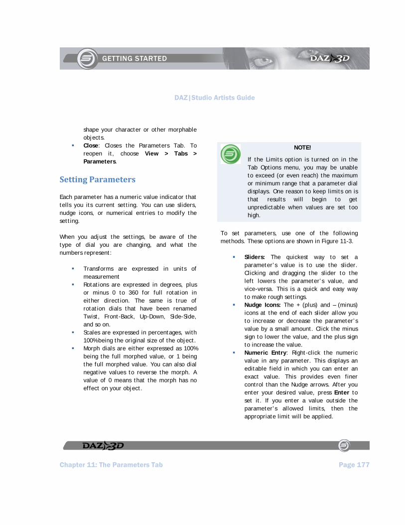
DAZ|Studio Artists Guide
Chapter 11: The Parameters Tab Page 177
shape your character or other morphable objects.
Close: Closes the Parameters Tab. To reopen it, choose View > Tabs > Parameters.
Setting Parameters
Each parameter has a numeric value indicator that tells you its current setting. You can use sliders, nudge icons, or numerical entries to modify the setting.
When you adjust the settings, be aware of the type of dial you are changing, and what the numbers represent:
Transforms are expressed in units of measurement
Rotations are expressed in degrees, plus or minus 0 to 360 for full rotation in either direction. The same is true of rotation dials that have been renamed Twist, Front-Back, Up-Down, Side-Side, and so on.
Scales are expressed in percentages, with 100% being the original size of the object.
Morph dials are either expressed as 100% being the full morphed value, or 1 being the full morphed value. You can also dial negative values to reverse the morph. A value of 0 means that the morph has no effect on your object.
NOTE!
If the Limits option is turned on in the Tab Options menu, you may be unable to exceed (or even reach) the maximum or minimum range that a parameter dial displays. One reason to keep limits on is that results will begin to get unpredictable when values are set too high.
To set parameters, use one of the following methods. These options are shown in Figure 11-3.
Sliders: The quickest way to set a parameter’s value is to use the slider. Clicking and dragging the slider to the left lowers the parameter’s value, and vice-versa. This is a quick and easy way to make rough settings.
Nudge Icons: The + (plus) and – (minus) icons at the end of each slider allow you to increase or decrease the parameter’s value by a small amount. Click the minus sign to lower the value, and the plus sign to increase the value.
Numeric Entry: Right-click the numeric value in any parameter. This displays an editable field in which you can enter an exact value. This provides even finer control than the Nudge arrows. After you enter your desired value, press Enter to set it. If you enter a value outside the parameter’s allowed limits, then the appropriate limit will be applied.
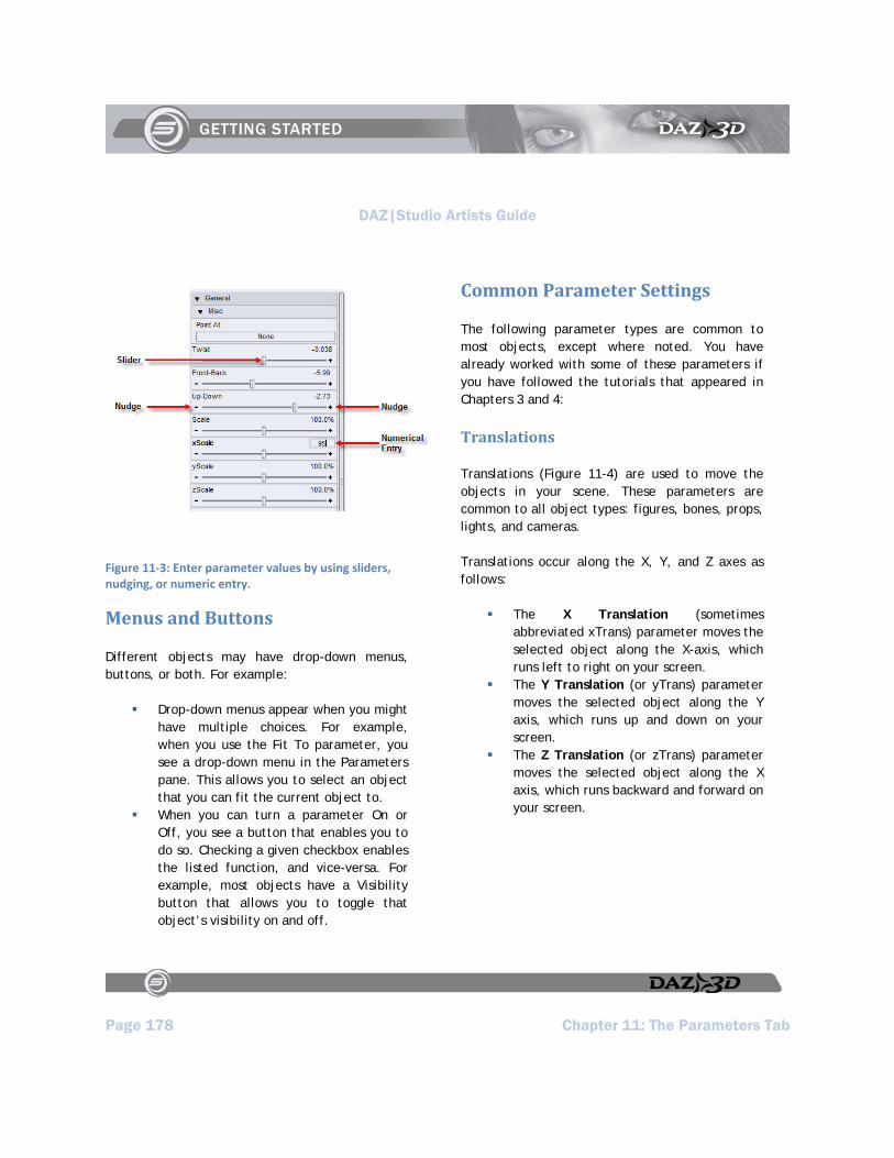
DAZ|Studio Artists Guide
Page 178 Chapter 11: The Parameters Tab
Figure 11‐3: Enter parameter values by using sliders, nudging, or numeric entry.
Menus and Buttons
Different objects may have drop-down menus, buttons, or both. For example:
Drop-down menus appear when you might have multiple choices. For example, when you use the Fit To parameter, you see a drop-down menu in the Parameters pane. This allows you to select an object that you can fit the current object to.
When you can turn a parameter On or Off, you see a button that enables you to do so. Checking a given checkbox enables the listed function, and vice-versa. For example, most objects have a Visibility button that allows you to toggle that object’s visibility on and off.
Common Parameter Settings
The following parameter types are common to most objects, except where noted. You have already worked with some of these parameters if you have followed the tutorials that appeared in Chapters 3 and 4:
Translations
Translations (Figure 11-4) are used to move the objects in your scene. These parameters are common to all object types: figures, bones, props, lights, and cameras.
Translations occur along the X, Y, and Z axes as follows:
The X Translation (sometimes abbreviated xTrans) parameter moves the selected object along the X-axis, which runs left to right on your screen.
The Y Translation (or yTrans) parameter moves the selected object along the Y axis, which runs up and down on your screen.
The Z Translation (or zTrans) parameter moves the selected object along the X axis, which runs backward and forward on your screen.

DAZ|Studio Artists Guide
Chapter 11: The Parameters Tab Page 179
Figure 11‐4: Translation parameters move an object in any direction.
Rotations
You can rotate any type of object in your scene, with the exception of point lights, seeing as they shine light in all directions. Translations and scales are somewhat obvious when it comes time to make adjustments. You move an object on the X axis to move it left or right, and scale the object along the X axis to widen it. You can also rotate objects along their X, Y, and/or Z axes, but a bit of explanation is needed to explain how rotation works.
The easiest way to explain rotation is to compare it to a pair of tires on an axle, examples of which are shown in Figure 11-5. The axle is the axis of rotation, and the tires rotate in the direction that is perpendicular to the axis. For example, when the front of the car is facing directly toward you, the axle is running left to right along the X axis. The tires rotate front to back.
Now, let’s say the car is tipped over on its side, so that the axle runs up and down along the Y axis, and the bottom of the car is facing toward you.
The only way the tires can turn in this case is side to side (or left to right).
Let’s turn the car again, so that the axle is running front to back, along the X axis. You are looking at the car from its side. Now, you see the tires turn clockwise or counter-clockwise.
Figure 11‐5: When rotating objects, think of the axis of rotation as equivalent to an axle on which tires rotate.
This is precisely how rotation works in the 3D world. The axis of rotation is fixed along the X, Y, or Z axes, in the same way that the tires are in the previous figure. As you try to determine which of the three parameters will properly rotate your object, think of the axis as being the “fixed”

DAZ|Studio Artists Guide
Page 180 Chapter 11: The Parameters Tab
direction. To summarize, the settings shown in Figure 11-6 work as follows:
The X Rotation (sometimes abbreviated xrot) parameter fixes object along the X-axis (left to right). Objects rotate front to back.
The Y Rotation (or yrot) parameter fixes the object along the Y-axis (up and down). Objects rotate side to side (or left to right).
The Z Rotation (or zrot) parameter fixes the object along the X axis (front to back), and rotates objects clockwise or counter-clockwise.
Figure 11‐6: Objects can be rotated along three different axes.
NOTE!
When a figure contains bones, as is the case with humans, animals, and poseable clothing, you will sometimes see the rotation parameters listed in more friendly terms: Twist, Bend, Side-Side, Up-Down, Front-Back, and so on. These are discussed in more detail in Chapter 14, “Posing and Moving Figures.”
Scale
Use the parameter dials in the Scale section when you want to increase or decrease the size of an object:
Scale: Scales the selected objects equally in all directions.
xScale: Scales the selected objects along the X (left to right) axis, making the object wider or narrower.
yScale: Scales the selected objects along the Y (up and down) axis, making the object shorter or taller.
zScale: Scales the selected objects along the Z (front to back) axis, making the object deeper or shallower.
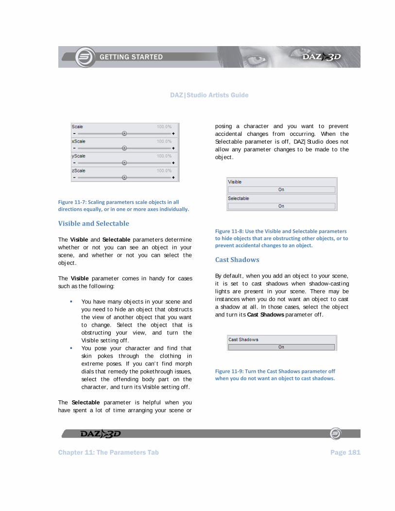
DAZ|Studio Artists Guide
Chapter 11: The Parameters Tab Page 181
Figure 11‐7: Scaling parameters scale objects in all directions equally, or in one or more axes individually.
Visible and Selectable
The Visible and Selectable parameters determine whether or not you can see an object in your scene, and whether or not you can select the object.
The Visible parameter comes in handy for cases such as the following:
You have many objects in your scene and you need to hide an object that obstructs the view of another object that you want to change. Select the object that is obstructing your view, and turn the Visible setting off.
You pose your character and find that skin pokes through the clothing in extreme poses. If you can’t find morph dials that remedy the pokethrough issues, select the offending body part on the character, and turn its Visible setting off.
The Selectable parameter is helpful when you have spent a lot of time arranging your scene or
posing a character and you want to prevent accidental changes from occurring. When the Selectable parameter is off, DAZ|Studio does not allow any parameter changes to be made to the object.
Figure 11‐8: Use the Visible and Selectable parameters to hide objects that are obstructing other objects, or to prevent accidental changes to an object.
Cast Shadows
By default, when you add an object to your scene, it is set to cast shadows when shadow-casting lights are present in your scene. There may be instances when you do not want an object to cast a shadow at all. In those cases, select the object and turn its Cast Shadows parameter off.
Figure 11‐9: Turn the Cast Shadows parameter off when you do not want an object to cast shadows.
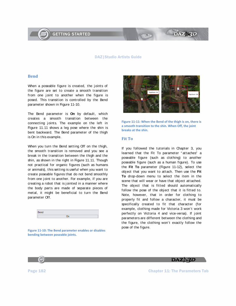
DAZ|Studio Artists Guide
Page 182 Chapter 11: The Parameters Tab
Bend
When a poseable figure is created, the joints of the figure are set to create a smooth transition from one joint to another when the figure is posed. This transition is controlled by the Bend parameter shown in Figure 11-10.
The Bend parameter is On by default, which creates a smooth transition between the connecting joints. The example on the left in Figure 11.11 shows a leg pose where the shin is bent backward. The Bend parameter of the thigh is On in this example.
When you turn the Bend setting Off on the thigh, the smooth transition is removed and you see a break in the transition between the thigh and the shin, as shown in the right in Figure 11.11. Though not practical for organic figures (such as humans or animals), this setting is useful when you want to create poseable figures that do not bend smoothly from one joint to another. For example, if you are creating a robot that is jointed in a manner where the body parts are made of separate pieces of metal, it might be beneficial to turn the Bend parameter Off.
Figure 11‐10: The Bend parameter enables or disables bending between poseable joints.
Figure 11‐11: When the Bend of the thigh is on, there is a smooth transition to the shin. When Off, the joint breaks at the shin.
Fit To
If you followed the tutorials in Chapter 3, you learned that the Fit To parameter “attaches” a poseable figure (such as clothing) to another poseable figure (such as a human figure). To use the Fit To parameter (Figure 11-12), select the object that you want to attach. Then use the Fit To drop-down menu to select the item in the scene that will wear or have that object attached. The object that is fitted should automatically follow the pose of the object that it is fitted to. Note, however, that in order for clothing to properly fit and follow a character, it must be specifically created to fit that character (for example, clothing made for Victoria 3 won’t work perfectly on Victoria 4 and vice-versa). If joint parameters are different between the clothing and the figure, the clothing won’t exactly follow the pose of the figure.
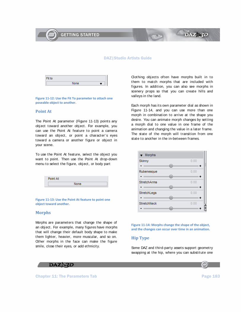
DAZ|Studio Artists Guide
Chapter 11: The Parameters Tab Page 183
Figure 11‐12: Use the Fit To parameter to attach one poseable object to another.
Point At
The Point At parameter (Figure 11-13) points any object toward another object. For example, you can use the Point At feature to point a camera toward an object, or point a character’s eyes toward a camera or another figure or object in your scene.
To use the Point At feature, select the object you want to point. Then use the Point At drop-down menu to select the figure, object, or body part
Figure 11‐13: Use the Point At feature to point one object toward another.
Morphs
Morphs are parameters that change the shape of an object. For example, many figures have morphs that will change their default body shape to make them lighter, heavier, more muscular, and so on. Other morphs in the face can make the figure smile, close their eyes, or add ethnicity.
Clothing objects often have morphs built in to them to match morphs that are included with figures. In addition, you can also see morphs in scenery props so that you can create hills and valleys in the land.
Each morph has its own parameter dial as shown in Figure 11-14, and you can use more than one morph in combination to arrive at the shape you desire. You can animate morph changes by setting a morph dial to one value in one frame of the animation and changing the value in a later frame. The state of the morph will transition from one state to another in the in-between frames.
Figure 11‐14: Morphs change the shape of the object, and the changes can occur over time in an animation.
Hip Type
Some DAZ and third-party assets support geometry swapping at the hip, where you can substitute one

DAZ|Studio Artists Guide
Page 184 Chapter 11: The Parameters Tab
type of hip for another. The most common usage for this is to turn genitalia on and off for humanoid figures by swapping the hip geometry. If the figure supports it, you will see a button in the Parameters Tab to give you the option to change hip types for the given figure.
The Numeric Parameter Settings Dialog
When you double-click the name of a parameter that has a numeric value associated with it, the Parameter Settings dialog shown in Figure 11-15 opens. This dialog allows you to set the following options:
Name: Displays the name for the parameter. To change the name, select the text with your cursor and type a new name in the field.
Hidden: Determines whether or not the object is visible in the scene. Click to toggle the setting from No (which makes the object visible) to Yes (which hides the object).
Locked: Determines whether or not you are able to make changes to the parameter. Click to toggle the setting from No (which allows changes) to Yes (which prevents changes from occurring).
Value: Displays the current setting for the parameter. To change the setting, highlight the current setting and enter a new one.
Respect Limits: Determines whether or not the current parameter will remain within the minimum and maximum limits
that are set for it. Click the setting to change from Yes (which keeps the parameter within the limits) or No (which allows you to set the parameter beyond its limits).
Min Limit: Sets the minimum allowable value for the parameter dial. When the Respect Limits setting (above) is set to Yes, DAZ|Studio does not allow the minimum value to extend beyond this limit.
Max Limit: Sets the maximum allowable value for the parameter dial. When the Respect Limits setting (above) is set to Yes, DAZ|Studio does not allow the maximum value to extend beyond this limit.
Display As: Click this field to toggle display units between Value (for a numeric value) or Percent (for a percentage value).
Sensitivity: The Sensitivity field functions in one of two ways:
On a slider with limits, the Sensitivity value is the increment used each time you click a Nudge arrow.
On a slider without limits, the Sensitivity value sets both the Nudge arrow increments and the rate of change when you click and drag the slider.
Controllers: Informs you whether or not there are external controllers that are linked to the parameter.

DAZ|Studio Artists Guide
Chapter 11: The Parameters Tab Page 185
After you make your changes, click the Accept button to save them and close the dialog. Click the Cancel button to discard the changes and close the dialog. The Parameter Settings dialog will vary in appearance depending on the type of parameter you selected:
Figure 11‐15: Numeric parameter settings can be changed in the Parameter Settings dialog.
The Toggle Parameter Settings Dialog
When you double-click a parameter that has a toggle value associated with it (such as On/Off,
Yes/No) the Parameter Settings dialog shown in Figure 11-16 appears. The following settings are found in this dialog:
Figure 11‐16: Toggle parameters have slightly different options in the Parameter Settings dialog.
Name: Displays the name for the parameter. To change the name, select the text with your cursor and type a new name in the field.
Hidden: Determines whether or not the object is visible in the scene. Click to toggle the setting from No (which makes the object visible) to Yes (which hides the object).
Locked: Determines whether or not you are able to make changes to the parameter. Click to toggle the setting from No (which allows changes) to Yes (which prevents changes from occurring).

DAZ|Studio Artists Guide
Page 186 Chapter 11: The Parameters Tab
Value: Displays the current setting for the parameter. Click the current value to toggle to the other state.
Controllers: Informs you whether or not there are external controllers that are linked to the parameter.
Parameters vs. Morphs
At face value, parameters and morphs seem similar if not identical. There are, however, several key differences:
In general, parameters deal with object translation, rotation, and scale. Additionally, parameters are based on an item’s type (such as a light) and sub-type (a specific kind of light). For example, all lights have intensity controls that allow you to dim and brighten them. Spotlights
have rotation parameters, but Point Lights do not.
Morphs involve specific deformations applied to items in a scene that are otherwise known as mesh objects. These deformations are specifically created for a given item, and are only available when installed and the correct item is selected in your scene.
TIP!
While different, parameters and morphs share the same types of interface controls within DAZ|Studio. For simplicity, we will use the term “parameters” in this chapter to mean both general parameters and morphs.

DAZ|Studio Artists Guide
Chapter 12: The Timeline Tab Page 187
Chapter 12 : The Timeline Tab
The Timeline is a basic animation tool found within DAZ|Studio, which brings movement and motion to your scenes. Before we begin, a brief description of what animation is and how it works is in order.
Animation Basics
Animating a character involves a bit more than simply posing a character into a single static pose.
You should plan out ahead what movements your characters within a scene will make - the more detailed, the better. For example, a basic animation could depict a close-up of a character that tilts its head and smiles at the viewer. If the character also blinks, flares its nostrils, or narrows its eyelids while smiling, the animation becomes more believable and life-like.
Breaking it Down
An animation, while appearing fluid in its final form, is actually broken up into individual frames, much like individual frames on old-fashioned movie film. When DAZ|Studio processes an animation into a movie, it will render each frame, one at a time, to produce the final movie clip. This does not mean that you yourself are forced to set up each frame, however.
Using what is known as Linear Interpolation, DAZ|Studio itself works out what the intermediate
positions of each part in a scene will be between what are known as Keyframes. A Keyframe is a user-set position or rotation setting of an arm, eyeball, falling object, or what-have-you at a given point in time (for instance, the image above would represent a collage of individual keyframes in a diving animation).
Keyframes tell DAZ|Studio where and how you want everything to be at an exact moment in time. You can remove keyframes if you later decide to change something, or want to change the whole animation at any point in time.
Anatomy of the Timeline Tab
The Timeline Tab that comes with DAZ|Studio is a simple default tool that allows you to create and adjust basic animations. This tab is divided into several portions that are standard on almost any animation manipulation package. These controls are shown in Figure 1-1 and serve the following functions.
Figure 12‐1
Scrubber (1): Move the scrubber left to move backward through the animation, or right to move forward in the animation.
Total Frames (2): This will tell you how many frames are in the entire animation clip for this scene. Notice, in the tab above, that a 30-frame scene will have 31 frames. This 31st frame is a reference frame, and cannot be accessed or
DAZ|Studio Artists Guide
Chapter 12: The Timeline Tab Page 188
manipulated by the user. It is only used for internal purposes only, and will not affect the animation. In the window next to the Total: label, you can change this to reflect as many frames as you desire in an animation. Just remember to add one to the total number you want. For example, if you want a 900-frame animation (which by default is 30 seconds of video @ 30fps), you would enter 901 into the Total: field.
Current Range (3): This field lists the current range of frames displayed in the timeline. You can manually enter the beginning and end frame that you want displayed, or it will update itself to show the current range if you move the range slider carets to reflect which part of the graph you want to concentrate on.
Current Frame (4): This field shows you the frame currently displayed in the active 3d viewport, and shows you at what time-point of the video clip you are currently working (in hours : minutes : seconds : frames format).
FPS (Frames Per Second) Setting (5): This field shows you how many frames of animation will constitute one second of video playback time. By default this is set at 30 frames per second.
TIP!
Most people have eyes that automatically convert separate frames of animation into fluid motion at a minimum of 24 frames per second. The higher the FPS setting, the smoother the motion appears (and the smoother the linear interpolation calculations). However, this will also increase the number of frames required for the entire video clip, and will increase render times in proportion to the increase in setting.
Loop On/Off (6): This button will allow you to preview the animation within the currently selected range as either a single-run video (where it will run only once until you play it again), or as a loop (where it will run over and over continuously until you manually stop the playback). The button icon will change accordingly from a pair of linked arrows (loop), to a pair of unconnected arrows, depending on which setting you choose.
Add/Remove Keyframe (7): This button allows you to set a keyframe. A keyframe is defined as a point in the animation where you the user definitely want all portions within the frame to be positioned, and will be used as part of calculating interpolation. To add a keyframe, go to a frame where you want to set an important element of the scene to an intermediate position (such as an
DAZ|Studio Artists Guide
Page 189 Chapter 12: The Timeline Tab
arm in mid-swing, an eyelid closed fully, a ball striking the ground in mid-bounce, etc). Click the Add Keyframe button to set the keyframe for the current frame.
Go to First Frame (8): This button will take you and your current 3d viewport back to the first frame in your currently selected range.
Previous Keyframe (9): This button will take you to the previous closest keyframe (within the currently selected range) before the frame you are currently in.
Back One Frame (10): Fairly self-explanatory - this button will take you back one frame from the currently selected one.
Play/Stop (11): This button will Play the whole animation, starting at the current frame. If you have looping enabled (see previous page), the preview will play
continuously over and over again through the currently selected range until you stop it. While playing, the icon on the button will change to resemble the Stop button, which you can then press to stop the animation preview at any time.
Ahead One Frame (12): This button will advance you ahead one frame from the currently selected one.
Next Keyframe (13): This button will take you to the next keyframe you have set in your currently selected range.
Move to End Frame (14): This button will take you to the last frame within your currently selected range.
Remove Keyframe (15): To remove a keyframe, go to an active keyframe (you can use the previous/next keyframe buttons to do this), and select the Remove Keyframe button.

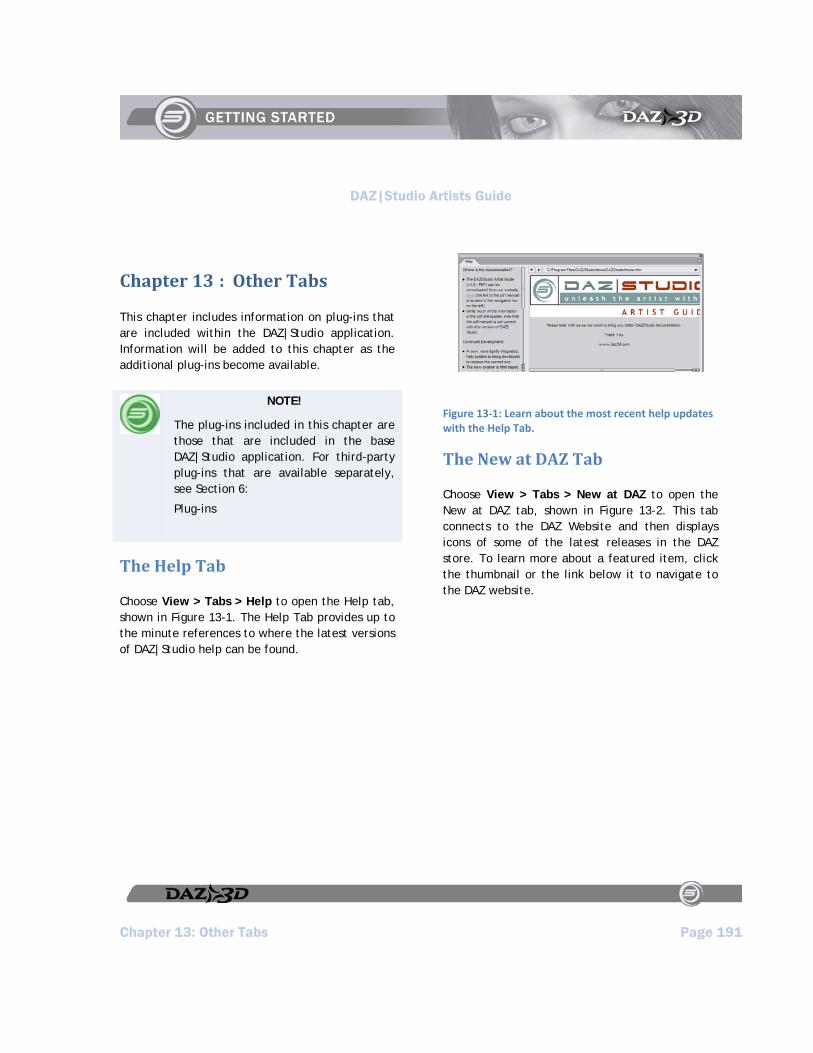
DAZ|Studio Artists Guide
Chapter 13: Other Tabs Page 191
Chapter 13 : Other Tabs
This chapter includes information on plug-ins that are included within the DAZ|Studio application. Information will be added to this chapter as the additional plug-ins become available.
NOTE!
The plug-ins included in this chapter are those that are included in the base DAZ|Studio application. For third-party plug-ins that are available separately, see Section 6:
Plug-ins
The Help Tab
Choose View > Tabs > Help to open the Help tab, shown in Figure 13-1. The Help Tab provides up to the minute references to where the latest versions of DAZ|Studio help can be found.
Figure 13‐1: Learn about the most recent help updates with the Help Tab.
The New at DAZ Tab
Choose View > Tabs > New at DAZ to open the New at DAZ tab, shown in Figure 13-2. This tab connects to the DAZ Website and then displays icons of some of the latest releases in the DAZ store. To learn more about a featured item, click the thumbnail or the link below it to navigate to the DAZ website.
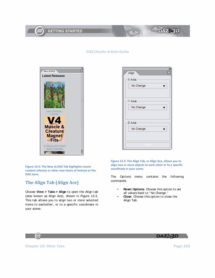
DAZ|Studio Artists Guide
Chapter 13: Other Tabs Page 192
Figure 13‐2: The New at DAZ Tab highlights recent content releases or other new items of interest at the DAZ store.
The Align Tab (Align Ace)
Choose View > Tabs > Align to open the Align tab (also known as Align Ace), shown in Figure 13-3. This tab allows you to align two or more selected items to eachother, or to a specific coordinate in your scene.
Figure 13‐3: The Align Tab, or Align Ace, allows you to align two or more objects to each other or to a specific coordinate in your scene.
The Options menu contains the following commands:
Reset Options: Choose this option to set all values back to “No Change.”
Close: Choose this option to close the Align Tab.
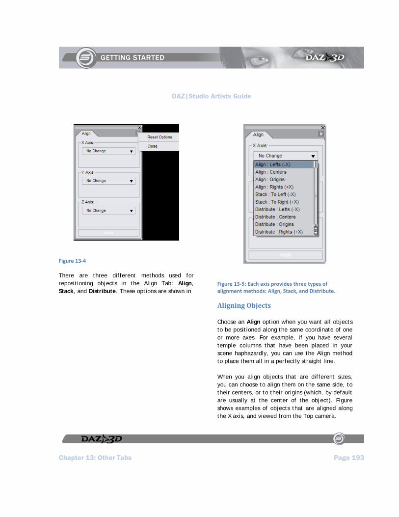
DAZ|Studio Artists Guide
Chapter 13: Other Tabs Page 193
Figure 13‐4
There are three different methods used for repositioning objects in the Align Tab: Align, Stack, and Distribute. These options are shown in
Figure 13‐5: Each axis provides three types of alignment methods: Align, Stack, and Distribute.
Aligning Objects
Choose an Align option when you want all objects to be positioned along the same coordinate of one or more axes. For example, if you have several temple columns that have been placed in your scene haphazardly, you can use the Align method to place them all in a perfectly straight line.
When you align objects that are different sizes, you can choose to align them on the same side, to their centers, or to their origins (which, by default are usually at the center of the object). Figure shows examples of objects that are aligned along the X axis, and viewed from the Top camera.
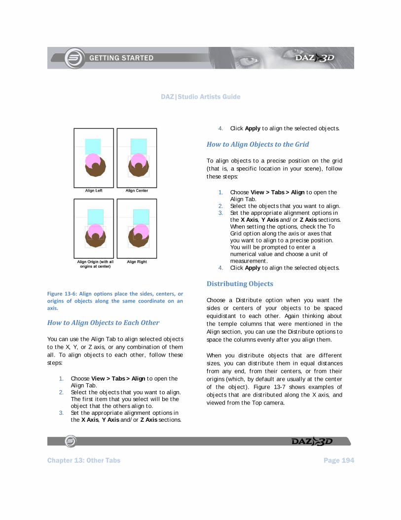
DAZ|Studio Artists Guide
Chapter 13: Other Tabs Page 194
Figure 13‐6: Align options place the sides, centers, or origins of objects along the same coordinate on an axis.
How to Align Objects to Each Other
You can use the Align Tab to align selected objects to the X, Y, or Z axis, or any combination of them all. To align objects to each other, follow these steps:
1. Choose View > Tabs > Align to open the Align Tab.
2. Select the objects that you want to align. The first item that you select will be the object that the others align to.
3. Set the appropriate alignment options in the X Axis, Y Axis and/or Z Axis sections.
4. Click Apply to align the selected objects.
How to Align Objects to the Grid
To align objects to a precise position on the grid (that is, a specific location in your scene), follow these steps:
1. Choose View > Tabs > Align to open the Align Tab.
2. Select the objects that you want to align. 3. Set the appropriate alignment options in
the X Axis, Y Axis and/or Z Axis sections. When setting the options, check the To Grid option along the axis or axes that you want to align to a precise position. You will be prompted to enter a numerical value and choose a unit of measurement.
4. Click Apply to align the selected objects.
Distributing Objects
Choose a Distribute option when you want the sides or centers of your objects to be spaced equidistant to each other. Again thinking about the temple columns that were mentioned in the Align section, you can use the Distribute options to space the columns evenly after you align them.
When you distribute objects that are different sizes, you can distribute them in equal distances from any end, from their centers, or from their origins (which, by default are usually at the center of the object). Figure 13-7 shows examples of objects that are distributed along the X axis, and viewed from the Top camera.

DAZ|Studio Artists Guide
Chapter 13: Other Tabs Page 195
Figure 13‐7: Use the Distribute options to space selected objects evenly based on their ends, centers, or origins.
How to Distribute Objects
To align objects to a precise position on the grid (that is, a specific location in your scene), follow these steps:
1. Choose View > Tabs > Align to open the Align Tab.
2. Select the objects that you want to distribute evenly. Select them in the order in which you want to distribute them.
3. Set the appropriate alignment options in the X Axis, Y Axis and/or Z Axis sections:
To distribute objects so that they are evenly spaced on their end points, choose one of the options that defines which end point you want to distribute by (Lefts, Rights, Tops, Bottoms, Fronts, or Backs, depending on the axis of distribution).
To distribute objects so that they are evenly spaced according to their centers, choose the Distribute: Centers option from any axis.
To distribute objects so that they are evenly spaced according to their origin point, choose the Distribute: Origins option from any axis.
4. Click Apply to distribute the selected objects.
Stacking Objects
Choose a Stack option when you want your objects to butt up against each other along one or more axes. The Stack option uses the boundaries of each object as a reference point, and places the boundaries together with no space between them. Objects are stacked side to side (Lefts, Rights, Tops, Bottoms, Fronts, or Backs) depending on the axis you choose to perform the stacking operation.
Figure 13-8 shows examples of objects before they are stacked along the X axis, as viewed from the top camera. The cone (larger circle) is selected first, followed by the cylinder (smaller circle) and the cube. Notice that when these objects are
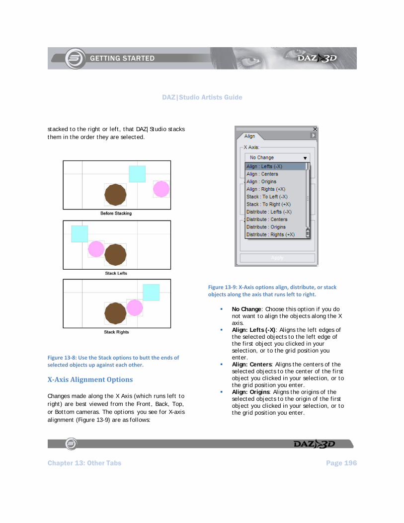
DAZ|Studio Artists Guide
Chapter 13: Other Tabs Page 196
stacked to the right or left, that DAZ|Studio stacks them in the order they are selected.
Figure 13‐8: Use the Stack options to butt the ends of selected objects up against each other.
XAxis Alignment Options
Changes made along the X Axis (which runs left to right) are best viewed from the Front, Back, Top, or Bottom cameras. The options you see for X-axis alignment (Figure 13-9) are as follows:
Figure 13‐9: X‐Axis options align, distribute, or stack objects along the axis that runs left to right.
No Change: Choose this option if you do not want to align the objects along the X axis.
Align: Lefts (-X): Aligns the left edges of the selected objects to the left edge of the first object you clicked in your selection, or to the grid position you enter.
Align: Centers: Aligns the centers of the selected objects to the center of the first object you clicked in your selection, or to the grid position you enter.
Align: Origins: Aligns the origins of the selected objects to the origin of the first object you clicked in your selection, or to the grid position you enter.
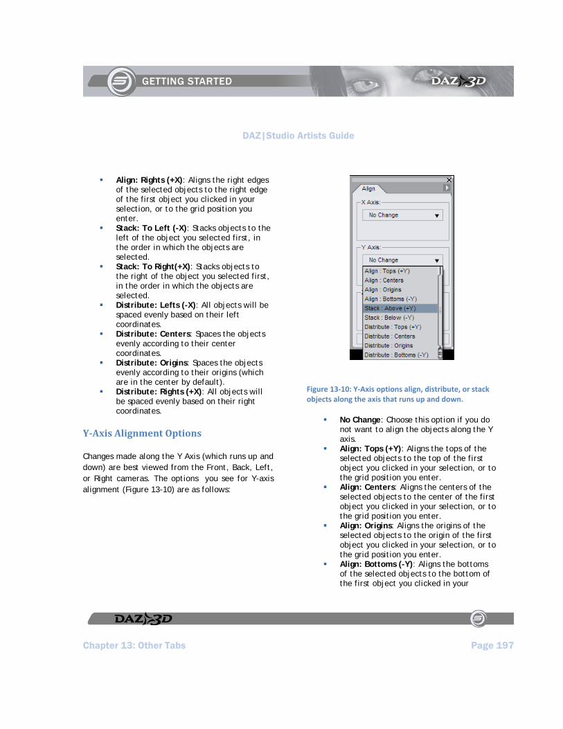
DAZ|Studio Artists Guide
Chapter 13: Other Tabs Page 197
Align: Rights (+X): Aligns the right edges of the selected objects to the right edge of the first object you clicked in your selection, or to the grid position you enter.
Stack: To Left (-X): Stacks objects to the left of the object you selected first, in the order in which the objects are selected.
Stack: To Right(+X): Stacks objects to the right of the object you selected first, in the order in which the objects are selected.
Distribute: Lefts (-X): All objects will be spaced evenly based on their left coordinates.
Distribute: Centers: Spaces the objects evenly according to their center coordinates.
Distribute: Origins: Spaces the objects evenly according to their origins (which are in the center by default).
Distribute: Rights (+X): All objects will be spaced evenly based on their right coordinates.
YAxis Alignment Options
Changes made along the Y Axis (which runs up and down) are best viewed from the Front, Back, Left, or Right cameras. The options you see for Y-axis alignment (Figure 13-10) are as follows:
Figure 13‐10: Y‐Axis options align, distribute, or stack objects along the axis that runs up and down.
No Change: Choose this option if you do not want to align the objects along the Y axis.
Align: Tops (+Y): Aligns the tops of the selected objects to the top of the first object you clicked in your selection, or to the grid position you enter.
Align: Centers: Aligns the centers of the selected objects to the center of the first object you clicked in your selection, or to the grid position you enter.
Align: Origins: Aligns the origins of the selected objects to the origin of the first object you clicked in your selection, or to the grid position you enter.
Align: Bottoms (-Y): Aligns the bottoms of the selected objects to the bottom of the first object you clicked in your

DAZ|Studio Artists Guide
Chapter 13: Other Tabs Page 198
selection, or to the grid position you enter.
Stack: Above (+Y): Stacks objects above the object you selected first, in the order in which the objects are selected.
Stack: Below(-Y): Stacks objects below the object you selected first, in the order in which the objects are selected.
Distribute: Tops (+Y): All objects will be spaced evenly based on their top coordinates.
Distribute: Centers: Spaces the objects evenly according to their center coordinates.
Distribute: Origins: Spaces the objects evenly according to their origins (which are in the center by default).
Distribute: Bottoms (-Y): All objects will be spaced evenly based on their bottom coordinates.
ZAxis Alignment Options
Changes made along the Z Axis (which runs front to back) are best viewed from the Top, Bottom, Left, or Right cameras. The options you see for Z-axis alignment (Figure 13-11) are as follows:
Figure 13‐11: Z‐Axis options align, distribute, or stack objects along the axis that runs front to back.
No Change: Choose this option if you do not want to align the objects along the Y axis.
Align: Fronts (+Z): Aligns the fronts of the selected objects to the front of the first object you clicked in your selection, or to the grid position you enter.
Align: Centers: Aligns the centers of the selected objects to the center of the first object you clicked in your selection, or to the grid position you enter.
Align: Origins: Aligns the origins of the selected objects to the origin of the first object you clicked in your selection, or to the grid position you enter.

DAZ|Studio Artists Guide
Chapter 13: Other Tabs Page 199
Align: Backs (-Z): Aligns the backs of the selected objects to the back of the first object you clicked in your selection, or to the grid position you enter.
Stack: In Front (+Z): Stacks objects in front of the object you selected first, in the order in which the objects are selected.
Stack: Behind (-Z): Stacks objects behind the object you selected first, in the order in which the objects are selected.
Distribute: Fronts (+Z): All objects will be spaced evenly based on their front coordinates.
Distribute: Centers: Spaces the objects evenly according to their center coordinates.
Distribute: Origins: Spaces the objects evenly according to their origins (which are in the center by default).
Distribute: Backs (-Z): All objects will be spaced evenly based on their bottom coordinates.
The Tool Tab
Choose View > Tabs > Tool to open the Tool tab, shown in Figure 13-12. This tab is used in conjunction with PowerPose, but may also be used in conjunction with other plug-ins where noted. See Chapter 19: PowerPose for more information on how to use this tab in conjunction with the PowerPose tab.
Figure 13‐12: Use the Tool Tab in conjunction with the PowerPose Tab, or other plug‐ins that may require it.
The DForm Tab
Choose View > Tabs > D-Form to open the D-Form tab, shown in Figure 13-13. The D-Form plug-in allows you to create and save custom morphs that shape characters, clothing, and objects in any way that you choose. For more information regarding this plug-in see Chapter 20 : D-Form.
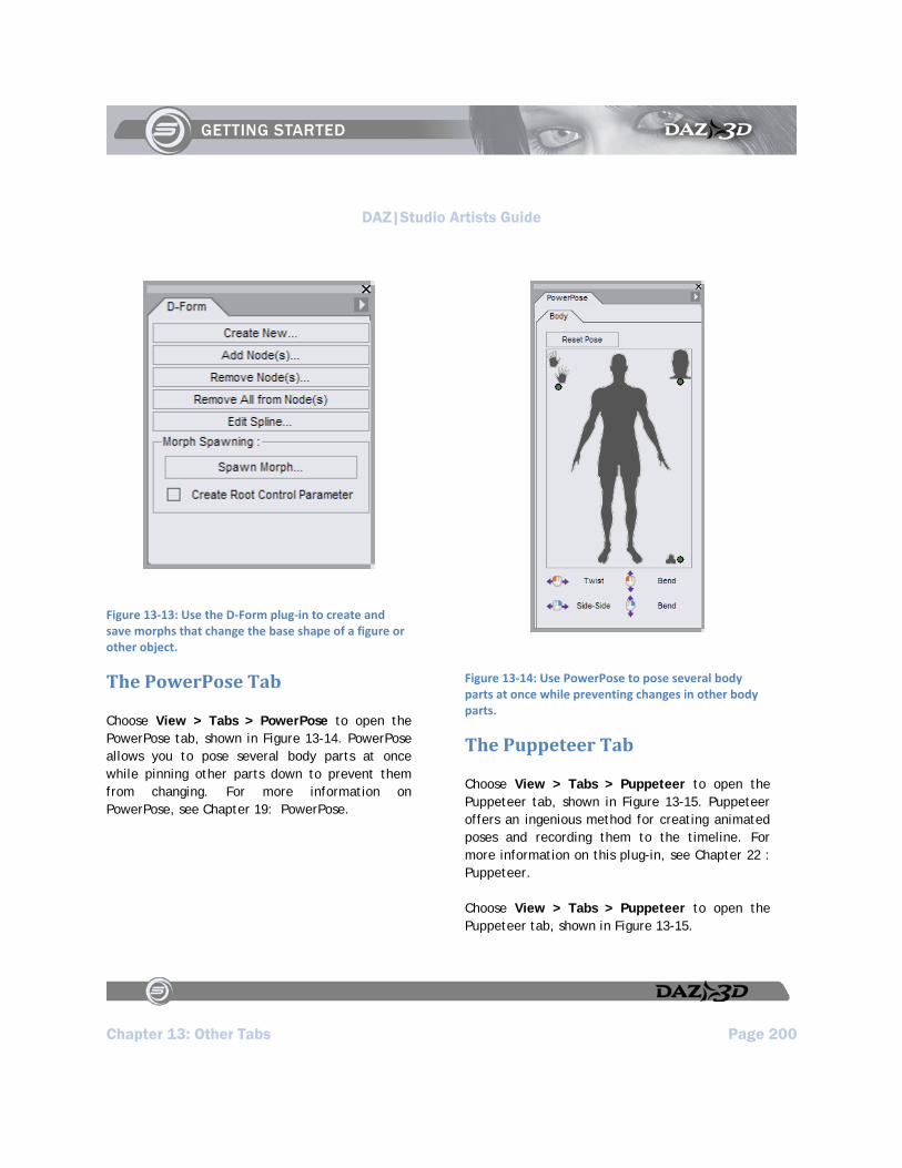
DAZ|Studio Artists Guide
Chapter 13: Other Tabs Page 200
Figure 13‐13: Use the D‐Form plug‐in to create and save morphs that change the base shape of a figure or other object.
The PowerPose Tab
Choose View > Tabs > PowerPose to open the PowerPose tab, shown in Figure 13-14. PowerPose allows you to pose several body parts at once while pinning other parts down to prevent them from changing. For more information on PowerPose, see Chapter 19: PowerPose.
Figure 13‐14: Use PowerPose to pose several body parts at once while preventing changes in other body parts.
The Puppeteer Tab
Choose View > Tabs > Puppeteer to open the Puppeteer tab, shown in Figure 13-15. Puppeteer offers an ingenious method for creating animated poses and recording them to the timeline. For more information on this plug-in, see Chapter 22 : Puppeteer.
Choose View > Tabs > Puppeteer to open the Puppeteer tab, shown in Figure 13-15.
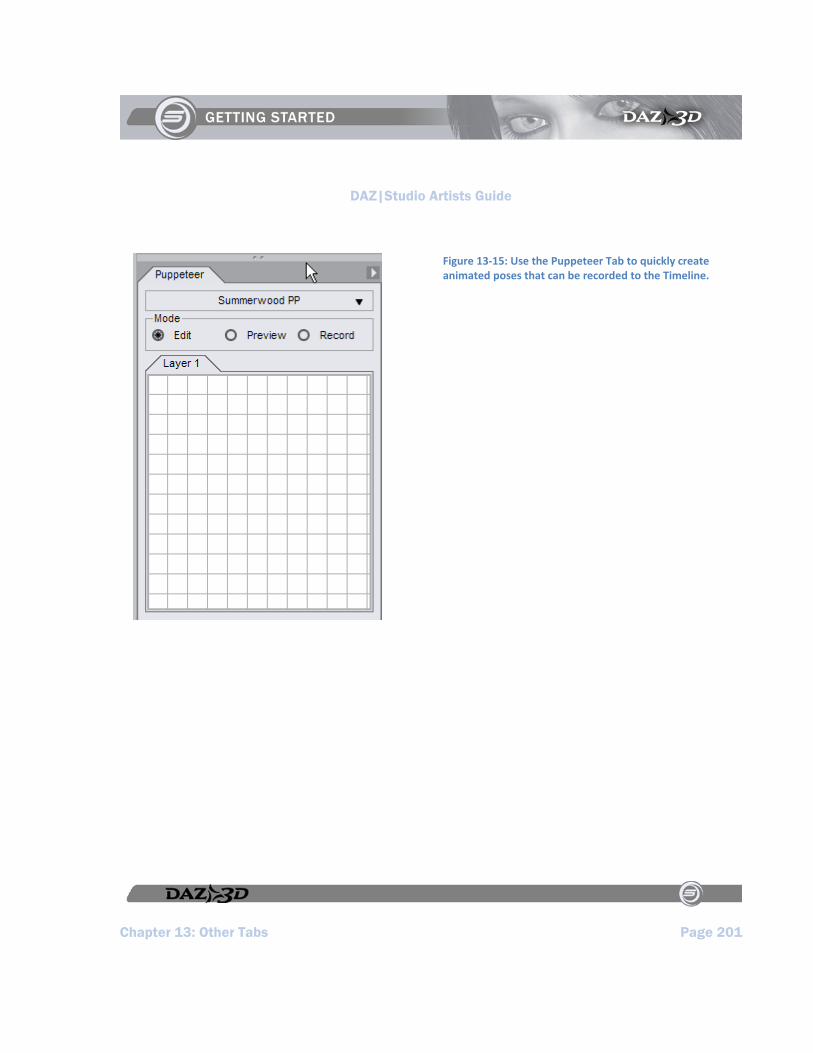
DAZ|Studio Artists Guide
Chapter 13: Other Tabs Page 201
Figure 13‐15: Use the Puppeteer Tab to quickly create animated poses that can be recorded to the Timeline.

DAZ|Studio Artists Guide
DAZ|Studio Artists Guide Page 203
Section 5:
Building and Rendering Scenes


DAZ|Studio Artists Guide
Chapter 14: Posing and Moving Figures Page 205
Chapter 14 : Posing and Moving Figures
Posing figures is one of DAZ|Studio’s central functions. There are several ways to pose figures. Let’s discuss each method in more detail.
Selecting Which Joints to Move
Before you can pose a figure, you must select the bone you wish to move. There are two ways to select bones:
Click the desired bone in any viewport. For example, if you want to bend the left leg at the knee, click the left shin.
Select the desired bone within the Scene Tab.
The Bone Manipulators appear at the selected bone’s origin whenever you select a bone. These controls will vary depending on the currently selected mode (as selected in the Toolbar - Rotate, Translate, or Scale). You must select the correct bone(s) on the correct figure in order to achieve the desired results. This sounds obvious at first, but may require some advance planning. In many cases, you will need to move several bones in order to achieve the final result. For example, if you want your figure to salute, you will need to move the right shoulder, forearm, and hand. When working with multiple bones, it’s usually best to start at the parent and work towards the children. This helps cut down on repetitive repositioning of the child bones. In this example, you’ll want to:
1. Apply some rotation and twist to the shoulder. Try applying -75 degrees of twist and 20 degrees of bend.
2. Twist and bend the elbow. Try applying -85 degrees of twist and 120 degrees of bend.
3. Bend the hand a little. Try applying -3 degrees of twist and 2.05 degrees of bend.
As you can see, starting at the hand in this case would have made the process far more time consuming and difficult. That said, there are times when it may be a good idea to start at the child bones. For example, if you are placing a prop in a figure’s hand, you might want to parent the prop to the hand, and adjust the hand into a realistic grasp before creating the pose. In this example, starting at the child ends (the fingers) will ensure that the prop will remain in the correct position relative to the figure’s hand
Direct Manipulation
Direct manipulation is the easiest and fastest way to adjust your figure’s pose. At its most basic, the process is as follows:
1. Select the bone to move. 2. Click and drag the Bone Manipulators to
move the joint.
This method is both easy and fast. Some users use this method to move figures into their rough positions, then switch to the Parameters Tab to make fine adjustments. The precision of this method depends on your viewing angle and
DAZ|Studio Artists Guide
Page 206 Chapter 14: Posing and Moving Figures
distance; the closer you are the object you’re manipulating, the finer the control you will have.
TIP!
You could use one viewport, one at a wide angle, the other zoomed in, to give to you both gross and fine control using the Bone Manipulators.
Manipulation Movement Modes
There are three ways to move figures and their bones:
Rotation: When you select a bone, rotation occurs at that bone’s parent joint. For example, if you select the forearm, the bending will occur at the elbow. The hip is the parent bone for the entire figure. If you select the hip, you will rotate the entire figure.
Translation: You usually should not translate individual joints, since doing so would result in scaling the affected bone. The hip is the parent bone for the entire figure. If you select the hip, you will translate the entire figure.
Scale: When you select a bone, scaling occurs along the entire bone. For example, if you select the forearm, the entire forearm will expand or contract along your selected axis or axes. The hip is the parent bone for the entire figure. If you select the hip, you will scale the entire figure.
Applying Pose Presets
Many content creators create custom poses for figures. Pose Presets are a fast way to get great results without having to spend a lot of time fine-tuning each bone. To apply a custom pose to a figure:
1. Select the figure to apply the pose to. 2. Locate the folder containing your desired
pose using the Content Tab. 3. Double-click your desired pose.
Your figure will assume the selected pose automatically.
Moving Figures
To move a figure:
1. Select the desired figure’s root node. 2. Use the Rotation, Translation, and/or
Scale manipulators as desired.
Applying Morphs
Morphs are specific distortions of mesh created for specific figures. These can range from blinking an eyelid, to instantly creating a weightlifter’s body-shape, to anywhere or anything in between.
To apply a morph to your figure, select your desired morph slider in the Parameters Tab and assign it a new value. Positive values apply the selected morph as created, while negative numbers apply the opposite of the selected morph. For example, applying a negative value to
DAZ|Studio Artists Guide
Chapter 14: Posing and Moving Figures Page 207
a smile morph might result in a frown. Applying large positive or negative values can result in excessive distortion and can even break the polygon mesh. A jagged edge appears when there are breaks in the mesh. When working with morph targets, it’s usually best to change values a little at a time if you’re not sure of the results. You can use as many morphs as you like in any combination.
Different figures come with different default morphs, and you can always add more with certain packages available for purchase or download. DAZ figures include hundreds of morphs to allow virtually unlimited customization.
Applying Clothing Figures
As you will soon notice, most figures are nude when they first load into the Scene. This allows you the greatest possible flexibility to add clothing (or not...) Creating a dressed figure would require that the model and clothing be the same actual mesh object, thus limiting you to only one outfit for that figure.
From a technical standpoint, clothing items are figures with body parts and bones of their own. In other words, they are functionally identical to figures, such as Michael and Victoria. Select an appropriate clothing item in the Content Tab and add it to your scene. You will see its root node and bones listed in the Scene Tab.
Each figure has a unique bone structure tailored to the specific mesh object. In addition, each joint between bones is specifically designed to work
with that figure’s mesh. In order to fit properly, clothing items must have both a bone structure and joint settings that are similar to those of the underlying figure (just as your own clothes must be sized and tailored to fit your body). Therefore, each item of clothing is specifically designed to fit a certain figure.
There are two ways to apply clothing to a figure (if the clothing item was originally created with the ability to fit itself to a figure):
Automatic Mode
To fit clothing to your figure automatically:
1. Select the figure to apply the clothing item to.
2. In the Content Tab, navigate to the folder containing the clothing item that you wish to fit to the figure.
3. Double-click the clothing item. The selected item is added to your scene and automatically fitted to your figure’s current pose (if the clothing was made for the figure).
Manual Mode
To fit clothing to your figure manually:
1. Add the clothing to your scene. 2. Select the clothing item by either clicking
its root object or by using the Scene Tab. 3. In the Parameters Tab, use the Fit To
drop-down menu to select the figure to fit the clothing item to. The selected
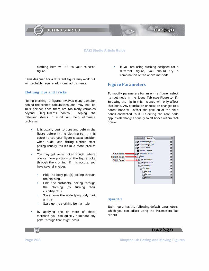
DAZ|Studio Artists Guide
Page 208 Chapter 14: Posing and Moving Figures
clothing item will fit to your selected figure.
Items designed for a different figure may work but will probably require additional adjustments.
Clothing Tips and Tricks
Fitting clothing to figures involves many complex behind-the-scenes calculations and may not be 100% perfect since there are too many variables beyond DAZ|Studio’s control. Keeping the following items in mind will help eliminate problems:
It is usually best to pose and deform the figure before fitting clothing to it. It is easier to see your figure’s exact position when nude, and fitting clothes after posing usually results in a more precise fit.
You may get some poke-through. where one or more portions of the figure poke through the clothing. If this occurs, you have several choices:
Hide the body part(s) poking through the clothing.
Hide the surface(s) poking through the clothing (by turning their visibility off.)
Scale down the underlying body part a little.
Scale up the clothing item a little.
By applying one or more of these methods, you can quickly eliminate any poke-through that might occur.
If you are using clothing designed for a different figure, you should try a combination of the above methods.
Figure Parameters
To modify parameters for an entire figure, select its root node in the Scene Tab (see Figure 14-1). Selecting the hip in this instance will only affect that bone. Any translation or rotation changes to a parent bone will affect the position of the child bones connected to it. Selecting the root node applies all changes equally to all bones within that figure.
Figure 14‐1
Each figure has the following default parameters, which you can adjust using the Parameters Tab sliders.
DAZ|Studio Artists Guide
Chapter 14: Posing and Moving Figures Page 209
Translate (XYZ): The Translate sliders translate the figure along its local X, Y, and Z axes without altering its rotation.
Rotate (XYZ): The Rotation sliders rotate the figure along its local X, Y, and Z axes without altering its location.
Scale (XYZ): The Scale sliders scale the figure along its local X, Y, and Z axes.
Fit To: The Fit To drop-down menu allows you to fit one figure to another. This is used for fitting clothing to figures. However, this menu appears for both clothing and figures, since they are technically the same. To cancel the selected fit, select None.
Visible: Checking the Visible checkbox makes the selected figure visible, and vice-versa.
Root Node Parameters
A figure’s root node has the following parameters:
Translate (XYZ): The Translate sliders translate the root bone along its local X, Y, and Z axes without altering its rotation.
Rotate (XYZ): The Rotation sliders rotate the root bone along its local X, Y, and Z axes without altering its location.
Scale (XYZ): The Scale sliders scale the root bone along its local X, Y, and Z axes.
Bones
Other bones will have various default parameters depending on their degrees of freedom and
parameter names assigned by the content creator. DAZ uses a standard convention for naming parameters based on their function. Some of the possible parameters are:
Bend : The Bend parameter rotates the selected bone about its own lateral axis, that is, the local axis that passes through the parent joint from left to right.
Side-Side: The Side-Side parameter rotates the selected bone toward or away from the figure’s centerline. In other words, the rotation occurs along the bone’s own transverse axis, that is, the local axis that passes through the parent joint from front to back.
Front-Back: The Front-Back parameter rotates the selected bone toward the figure’s anterior (front) or posterior (back) sides. For an example, hold your arm straight out and rotate your shoulder forward and back.
Twist: The Twist parameter rotates the selected bone about its own longitudinal axis, that is, the local axis that extends from parent joint to child joint.
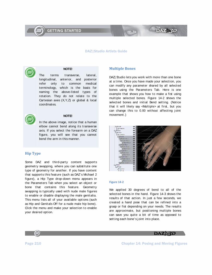
DAZ|Studio Artists Guide
Page 210 Chapter 14: Posing and Moving Figures
NOTE!
The terms transverse, lateral, longitudinal, anterior, and posterior refer only to common medical terminology, which is the basis for naming the above-listed types of rotation. They do not relate to the Cartesian axes (X,Y,Z) or global & local coordinates.
NOTE!
In the above image, notice that a human elbow cannot bend along its transverse axis. If you select the forearm on a DAZ figure, you will see that you cannot bend the arm in this manner.
Hip Type
Some DAZ and third-party content supports geometry swapping, where you can substitute one type of geometry for another. If you have content that supports this feature (such as DAZ’s Michael 2 figure), a Hip Type drop-down menu appears in the Parameters Tab when you select an object or bone that contains this feature. Geometry swapping is typically used with nude male figures to enable or disable displaying the male genitalia. This menu lists all of your available options (such as Hip and Genitals Off for a nude male hip bone). Click the menu and make your selection to enable your desired option.
Multiple Bones
DAZ|Studio lets you work with more than one bone at a time. Once you have made your selection, you can modify any parameter shared by all selected bones using the Parameters Tab. Here is one example that shows you how to make a fist using multiple selected bones. Figure 14-2 shows the selected bones and initial Bend setting. (Notice that it will likely say <Multiple> at first, but you can change this to 0.00 without affecting joint movement.)
Figure 14‐2
We applied 30 degrees of bend to all of the selected bones in the hand. Figure 14-3 shows the results of that action. In just a few seconds, we created a hand pose that can be refined into a grasp or fist depending on your needs. The results are approximate, but positioning multiple bones can save you quite a bit of time as opposed to setting each bone’s joint into place.
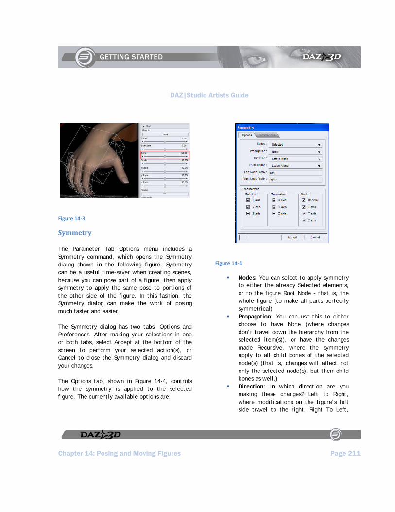
DAZ|Studio Artists Guide
Chapter 14: Posing and Moving Figures Page 211
Figure 14‐3
Symmetry
The Parameter Tab Options menu includes a Symmetry command, which opens the Symmetry dialog shown in the following figure. Symmetry can be a useful time-saver when creating scenes, because you can pose part of a figure, then apply symmetry to apply the same pose to portions of the other side of the figure. In this fashion, the Symmetry dialog can make the work of posing much faster and easier.
The Symmetry dialog has two tabs: Options and Preferences. After making your selections in one or both tabs, select Accept at the bottom of the screen to perform your selected action(s), or Cancel to close the Symmetry dialog and discard your changes.
The Options tab, shown in Figure 14-4, controls how the symmetry is applied to the selected figure. The currently available options are:
Figure 14‐4
Nodes: You can select to apply symmetry to either the already Selected elements, or to the figure Root Node - that is, the whole figure (to make all parts perfectly symmetrical)
Propagation: You can use this to either choose to have None (where changes don’t travel down the hierarchy from the selected item(s)), or have the changes made Recursive, where the symmetry apply to all child bones of the selected node(s) (that is, changes will affect not only the selected node(s), but their child bones as well.)
Direction: In which direction are you making these changes? Left to Right, where modifications on the figure’s left side travel to the right, Right To Left,

DAZ|Studio Artists Guide
Page 212 Chapter 14: Posing and Moving Figures
where modifications move in the opposite direction. You can also choose to Swap Left and Right, which is handy if you want to mirror a pose entirely.
Trunk Nodes: Determines what you want to do with the parts that run along the figure’s centerline (for example a human’s hip, abdomen, chest, neck, and head.) You can choose to Leave Alone, which will keep these items in place, Mirror Y|Z Rotations, which will set the centerline items’ Side-Side and Twist settings to the opposite of how they’re currently set, or you could choose to Zero Parameters, which will set those two parameters to Zero.
Left Node Prefix: Lets you set the first letters of all “left” child bones (that is, bones that are on a figure’s “left” side) that DAZ|Studio must look for when setting symmetry.
Right Node Prefix: Does the same as Left Node Prefix, but sets them for all of the affected “right” side bones.
Transforms: These checkboxes let you choose what it is you want to change - child bone rotation (on each axis), child bone translation (on each axis), or scale (overall scaling, or selectively on each axis as desired.)
Symmetry Preferences
The Preferences tab (Figure 14-5) controls which options are included when applying symmetry now and in future uses of this feature (until changed). The available options are:
Figure 14‐5
Set Preferred Options: This allows you to set these options now (or alternately, when the “Set Preferred Options on Accept” is selected, set the preferences whenever you use the feature.)
Read Preferred Options: This button lets you see what your saved settings for Symmetry are at this time.
Restore Default Options: This button resets all Symmetry settings back to factory defaults (which are shown in these illustrations.)
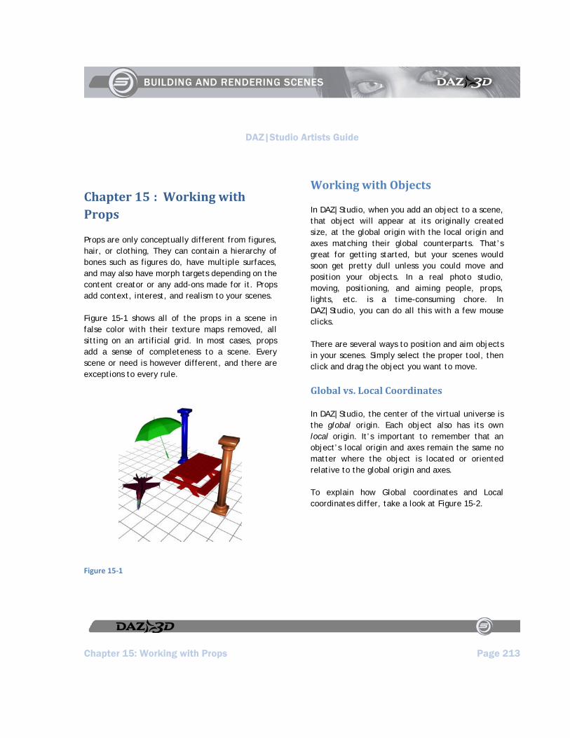
DAZ|Studio Artists Guide
Chapter 15: Working with Props Page 213
Chapter 15 : Working with Props
Props are only conceptually different from figures, hair, or clothing, They can contain a hierarchy of bones such as figures do, have multiple surfaces, and may also have morph targets depending on the content creator or any add-ons made for it. Props add context, interest, and realism to your scenes.
Figure 15-1 shows all of the props in a scene in false color with their texture maps removed, all sitting on an artificial grid. In most cases, props add a sense of completeness to a scene. Every scene or need is however different, and there are exceptions to every rule.
Figure 15‐1
Working with Objects
In DAZ|Studio, when you add an object to a scene, that object will appear at its originally created size, at the global origin with the local origin and axes matching their global counterparts. That’s great for getting started, but your scenes would soon get pretty dull unless you could move and position your objects. In a real photo studio, moving, positioning, and aiming people, props, lights, etc. is a time-consuming chore. In DAZ|Studio, you can do all this with a few mouse clicks.
There are several ways to position and aim objects in your scenes. Simply select the proper tool, then click and drag the object you want to move.
Global vs. Local Coordinates
In DAZ|Studio, the center of the virtual universe is the global origin. Each object also has its own local origin. It’s important to remember that an object’s local origin and axes remain the same no matter where the object is located or oriented relative to the global origin and axes.
To explain how Global coordinates and Local coordinates differ, take a look at Figure 15-2.
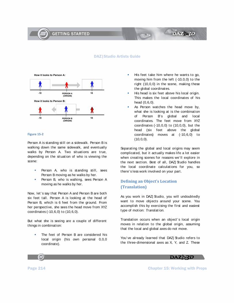
DAZ|Studio Artists Guide
Page 214 Chapter 15: Working with Props
Figure 15‐2
Person A is standing still on a sidewalk. Person B is walking down the same sidewalk, and eventually walks by Person A. Two situations are true, depending on the situation of who is viewing the scene:
Person A, who is standing still, sees Person B moving as he walks by her.
Person B, who is walking, sees Person A moving as he walks by her.
Now, let’s say that Person A and Person B are both six feet tall. Person A is looking at the head of Person B, which is 6 feet from the ground. From her perspective, she sees the head move from XYZ coordinates (-10,6,0) to (10,6,0).
But what she is seeing are a couple of different things in combination:
The feet of Person B are considered his local origin (his own personal 0,0,0 coordinate).
His feet take him where he wants to go, moving him from the left (-10,0,0) to the right (10,0,0) in the scene, making these the global coordinates.
His head is six feet above his local origin. This makes the local coordinates of his head (0,6,0).
As Person watches the head move by, what she is looking at is the combination of Person B’s global and local coordinates. The feet move from XYZ coordinates (-10,0,0) to (10,0,0), but the head (six feet above the global coordinates) moves at (-10,6,0) to (10,0,0).
Separating the global and local origins may seem complicated, but it actually makes life a lot easier when creating scenes for reasons we’ll explore in the next section. Best of all, DAZ|Studio handles the local coordinate calculations for you, so there’s less work involved on your part.
Defining an Object's Location (Translation)
As you work in DAZ|Studio, you will undoubtedly want to move objects around your scene. You accomplish this by exercising the first and easiest type of motion: Translation.
Translation occurs when an object’s local origin moves in relation to the global origin, assuming that the local and global axes do not move.
You’ve already learned that DAZ|Studio refers to the three-dimensional axes as X, Y, and Z. These
DAZ|Studio Artists Guide
Chapter 15: Working with Props Page 215
designations are part of what is known in 3D software programs as the Cartesian coordinate system. This system uses these three axes to represent the three dimensions.
The 3D universe extends an infinite negative and positive distance in each dimension, and the origin is literally the center of that universe. The center of the DAZ|Studio universe lies on the floor in the exact center of your scene. In fact, an item appears in the exact center when you first load an item from the Content Tab. From that point, you can use the xtran, ytran, or ztran Parameter dials to move your objects in a positive or negative direction as follows:
Move your object along the X axis (xtran) to move it left or right. Negative numbers move it to the left of the center point. Positive numbers move it to the right of the center point.
Move your object along the Y axis (ytran) to raise or lower it. Negative numbers move it down, and positive numbers move it up.
Move your object along the Z axis (ztran) to bring it closer or move it farther away. Negative numbers move it backward, and positive numbers move it forward.
To show an example, use the Create > New Primitive > Cube command to place a cube inside an empty scene. It loads in the exact center of the default viewport, at the (0,0,0) position.
Now, say you want to move your object 60 units to the left of the origin point. Select the cube, and adjust the X Translate dial to -60. The Cartesian
coordinate system now looks at the position as (-60,0,0) because the position is always listed as (X,Y,Z).
What if you want to move the object in more than one direction? You already have the cube moved 60 units to the left, but let’s say you want to position your object 70 units up, and 90 units backward. Simply adjust the Y Translate dial to 70 to move the cube up, and the Z Translate dial to -90 to move the object backward. The new Cartesian coordinates will now be (-60,70,-90).
You can see the results of the preceding example in Figure 15-3, where the original position is shown partially transparent. The red line indicates the X axis, the green line indicates the Y axis, and the blue line indicates the Z axis. The darker cube is the cube that has been relocated to the new position in the scene.
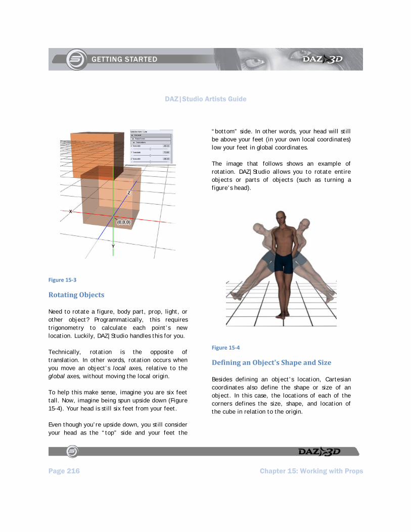
DAZ|Studio Artists Guide
Page 216 Chapter 15: Working with Props
Figure 15‐3
Rotating Objects
Need to rotate a figure, body part, prop, light, or other object? Programmatically, this requires trigonometry to calculate each point’s new location. Luckily, DAZ|Studio handles this for you.
Technically, rotation is the opposite of translation. In other words, rotation occurs when you move an object’s local axes, relative to the global axes, without moving the local origin.
To help this make sense, imagine you are six feet tall. Now, imagine being spun upside down (Figure 15-4). Your head is still six feet from your feet.
Even though you’re upside down, you still consider your head as the “top” side and your feet the
“bottom” side. In other words, your head will still be above your feet (in your own local coordinates) low your feet in global coordinates.
The image that follows shows an example of rotation. DAZ|Studio allows you to rotate entire objects or parts of objects (such as turning a figure’s head).
Figure 15‐4
Defining an Object's Shape and Size
Besides defining an object’s location, Cartesian coordinates also define the shape or size of an object. In this case, the locations of each of the corners defines the size, shape, and location of the cube in relation to the origin.
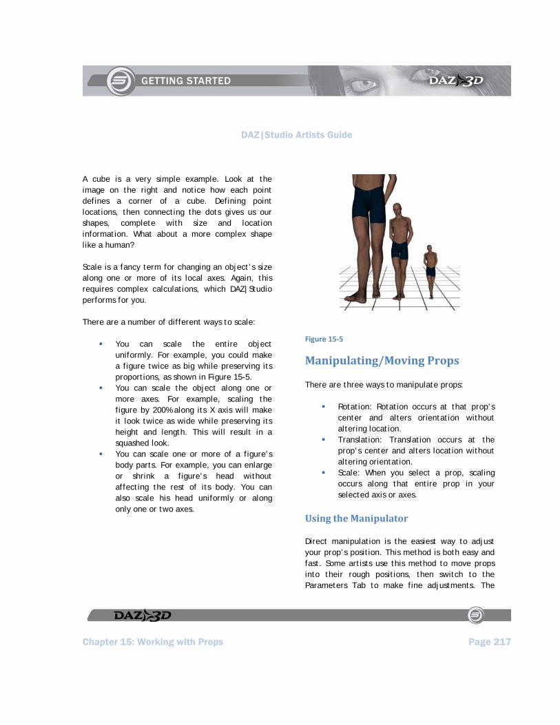
DAZ|Studio Artists Guide
Chapter 15: Working with Props Page 217
A cube is a very simple example. Look at the image on the right and notice how each point defines a corner of a cube. Defining point locations, then connecting the dots gives us our shapes, complete with size and location information. What about a more complex shape like a human?
Scale is a fancy term for changing an object’s size along one or more of its local axes. Again, this requires complex calculations, which DAZ|Studio performs for you.
There are a number of different ways to scale:
You can scale the entire object uniformly. For example, you could make a figure twice as big while preserving its proportions, as shown in Figure 15-5.
You can scale the object along one or more axes. For example, scaling the figure by 200% along its X axis will make it look twice as wide while preserving its height and length. This will result in a squashed look.
You can scale one or more of a figure’s body parts. For example, you can enlarge or shrink a figure’s head without affecting the rest of its body. You can also scale his head uniformly or along only one or two axes.
Figure 15‐5
Manipulating/Moving Props
There are three ways to manipulate props:
Rotation: Rotation occurs at that prop’s center and alters orientation without altering location.
Translation: Translation occurs at the prop’s center and alters location without altering orientation.
Scale: When you select a prop, scaling occurs along that entire prop in your selected axis or axes.
Using the Manipulator
Direct manipulation is the easiest way to adjust your prop’s position. This method is both easy and fast. Some artists use this method to move props into their rough positions, then switch to the Parameters Tab to make fine adjustments. The
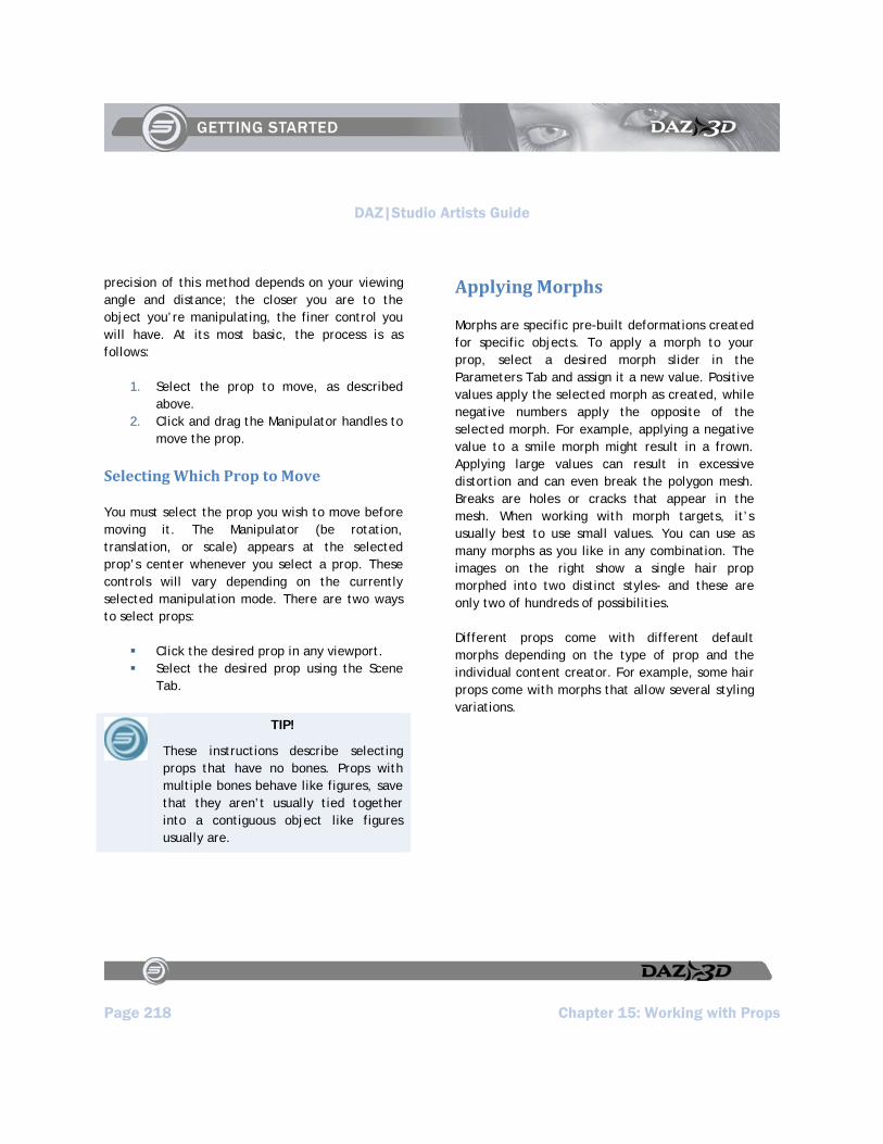
DAZ|Studio Artists Guide
Page 218 Chapter 15: Working with Props
precision of this method depends on your viewing angle and distance; the closer you are to the object you’re manipulating, the finer control you will have. At its most basic, the process is as follows:
1. Select the prop to move, as described above.
2. Click and drag the Manipulator handles to move the prop.
Selecting Which Prop to Move
You must select the prop you wish to move before moving it. The Manipulator (be rotation, translation, or scale) appears at the selected prop’s center whenever you select a prop. These controls will vary depending on the currently selected manipulation mode. There are two ways to select props:
Click the desired prop in any viewport. Select the desired prop using the Scene
Tab.
TIP!
These instructions describe selecting props that have no bones. Props with multiple bones behave like figures, save that they aren’t usually tied together into a contiguous object like figures usually are.
Applying Morphs
Morphs are specific pre-built deformations created for specific objects. To apply a morph to your prop, select a desired morph slider in the Parameters Tab and assign it a new value. Positive values apply the selected morph as created, while negative numbers apply the opposite of the selected morph. For example, applying a negative value to a smile morph might result in a frown. Applying large values can result in excessive distortion and can even break the polygon mesh. Breaks are holes or cracks that appear in the mesh. When working with morph targets, it’s usually best to use small values. You can use as many morphs as you like in any combination. The images on the right show a single hair prop morphed into two distinct styles- and these are only two of hundreds of possibilities.
Different props come with different default morphs depending on the type of prop and the individual content creator. For example, some hair props come with morphs that allow several styling variations.
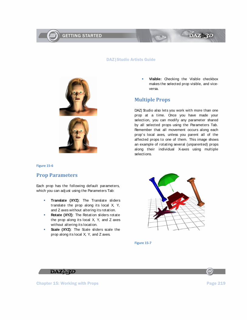
DAZ|Studio Artists Guide
Chapter 15: Working with Props Page 219
Figure 15‐6
Prop Parameters
Each prop has the following default parameters, which you can adjust using the Parameters Tab:
Translate (XYZ): The Translate sliders translate the prop along its local X, Y, and Z axes without altering its rotation.
Rotate (XYZ): The Rotation sliders rotate the prop along its local X, Y, and Z axes without altering its location.
Scale (XYZ): The Scale sliders scale the prop along its local X, Y, and Z axes.
Visible: Checking the Visible checkbox makes the selected prop visible, and vice-versa.
Multiple Props
DAZ|Studio also lets you work with more than one prop at a time. Once you have made your selection, you can modify any parameter shared by all selected props using the Parameters Tab. Remember that all movement occurs along each prop’s local axes, unless you parent all of the affected props to one of them. This image shows an example of rotating several (unparented) props along their individual X-axes using multiple selections.
Figure 15‐7


DAZ|Studio Artists Guide
Chapter 16: More About Lights Page 221
Chapter 16 : More About Lights
The Create menu allows you to create cameras and lights. When you select any of the Create Light buttons, the same options dialog will appear:
Like the camera creation dialog, the light creation dialog will ask you if you wish to give the new light a name (or will use the presented default name if you do not give the light a name), then it will present one of four options. Default settings center the light on the floor at the scene’s origin (0,0,0). When you apply the active viewport transforms, the light matches and orients itself in the same place and direction (if applicable) of the camera you’re currently using. You can also copy the properties of an existing light in the scene, or copy and replace a selected light in the scene. If you have no other lights in the scene, the third and fourth option will be grayed-out and unavailable to you.
Lights illuminate your scene and can create interesting effects and moods. DAZ|Studio includes a default light that lets you see and work with your scene.
Point Lights
Selecting Create > New Point Light allows you to create a new Point Light in your scene. A Point Light is an omni-directional light, such as that given off by an incandescent light bulb. Point Lights are the virtual equivalent of light bulbs. They put out a 360-degree sphere of light. The image shows a figure illuminated by a single white
Point Light. You will notice that it appears similar to a spot light. The difference is that the spot light is only casting light in one direction. In other words, an object behind a Spotlight will receive no illumination.
Figure 16‐1
Point Light Parameters
Each Point Light has the following default parameters, which you can adjust using the Parameters Tab.
Translate (XYZ): The Translate sliders translate the prop along its local X, Y, and Z axes without altering its rotation.
DAZ|Studio Artists Guide
Page 222 Chapter 16: More About Lights
Illumination: The Illumination pull-down menu contains the following options:
Off: Selecting Off turns the selected light off. If you decide to turn a light to 0% intensity, we suggest shutting it off using this menu to conserve computing resources when rendering.
Diffuse Only: Selecting Diffuse Only specifies that the light will only cast light in the normal (diffuse) channel without affecting highlights or specularity. This selection only affects the appearance of rendered images. It will appear the same as the On selection in the interactive display.
Specular Only: Selecting Specular Only specifies that the light will only cast light in the highlight (Specular) channel without affecting the diffuse channel. This selection only affects the appearance of rendered images. It will appear the same as the On selection in the interactive display.
On: Selecting On turns the selected light on. It will cast light in both diffuse and Specular channels. When a light is on, its brightness is determined by the Intensity slider.
Cast Shadow: Checking the Cast Shadows checkbox causes DAZ|Studio’s rendering engine to calculate shadows cast by objects within the selected light’s area of illumination.
Shadow Bias: The Shadow Bias parameter specifies how far to shift samples towards
the light source to prevent objects casting shadows across themselves (self-shadowing). Increasing the bias value increases the sample shift, and vice-versa.
Shadow Softness: The Shadow Softness parameter determines how soft the shadow’s edges are. Most shadows in nature have at least a little softness around the edges; almost none have completely sharp edges. Increasing the softness value increases the shadow edge softness and vice-versa.
Color: The Color indicator displays the light’s current color. Clicking it opens a standard Color Picker, which allows you to select your desired color for the currently selected light.
Intensity: The Intensity parameter adjusts the light’s brightness from 0% (totally off) to 100% (totally on) and beyond and up to 200% (be careful that you don’t ‘wash out’ the colors of everything in the light’s sphere of influence by going too far beyond 100%).
Distant Lights
Selecting Create > New Distant Light allows you to create a new Distant Light in your scene. A Distant Light is a directional light that covers an entire scene, but has no real source position. The closest real-world example would be sunlight.
Distant Lights are the virtual equivalent of the sun. They put out parallel light rays across your entire scene. Thus, their location does not matter-
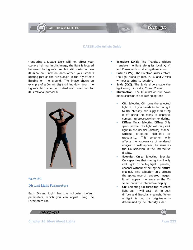
DAZ|Studio Artists Guide
Chapter 16: More About Lights Page 223
translating a Distant Light will not affect your scene’s lighting. In this image, the light is located between the figure’s feet but still casts uniform illumination. Rotation does affect your scene’s lighting just as the sun’s angle in the sky affects lighting on the ground. The image shows an example of a Distant Light shining down from the figure’s left side (with shadows turned on for illustrational purposes).
Figure 16‐2
Distant Light Parameters
Each Distant Light has the following default parameters, which you can adjust using the Parameters Tab:
Translate (XYZ): The Translate sliders translate the light along its local X, Y, and Z axes without altering its rotation.
Rotate (XYZ): The Rotation sliders rotate the light along its local X, Y, and Z axes without altering its location.
Scale (XYZ): The Scale sliders scale the light along its local X, Y, and Z axes.
Illumination: The Illumination pull-down menu contains the following options:
Off: Selecting Off turns the selected light off. If you decide to turn a light to 0% intensity, we suggest shutting it off using this menu to conserve computing resources when rendering.
Diffuse Only: Selecting Diffuse Only specifies that the light will only cast light in the normal (diffuse) channel without affecting highlights or specularity. This selection only affects the appearance of rendered images. It will appear the same as the On selection in the interactive display.
Specular Only: Selecting Specular Only specifies that the light will only cast light in the highlight (Specular) channel without affecting the diffuse channel. This selection only affects the appearance of rendered images. It will appear the same as the On selection in the interactive display
On: Selecting On turns the selected light on. It will cast light in both diffuse and Specular channels. When a light is on, its brightness is determined by the Intensity slider.

DAZ|Studio Artists Guide
Page 224 Chapter 16: More About Lights
Cast Shadow: Checking the Cast Shadows checkbox causes DAZ|Studio’s rendering engine to calculate shadows cast by objects within the selected light’s area of illumination.
Shadow Bias: The Shadow Bias parameter specifies how far to shift samples towards the light source to prevent objects casting shadows across themselves (self-shadowing). Increasing the bias value increases the sample shift, and vice-versa.
Shadow Softness: The Shadow Softness parameter determines how soft the shadow’s edges are. Most shadows in nature have at least a little softness around the edges; almost none have completely sharp edges. Increasing the softness value increases the shadow edge softness and vice-versa.
Color: The Color indicator displays the light’s current color. Clicking it opens a standard Color Picker, which allows you to select your desired color for the currently selected light.
Intensity: The Intensity parameter adjusts the light’s brightness from 0% (totally off) to 100% (totally on) up to 200%
Spot Lights
Selecting Create > New Spotlight allows you to create a new Spotlight in your scene. A Spotlight is a directional light that covers an adjustable area in the shape of a cone, such as a flashlight..
Spotlights emit a cone of light in a certain direction. You can control the direction and width of the cone in degrees. As mentioned above, the difference between spot lights and Point Lights can be hard to see from certain angles. The main thing to remember is that spot lights only cast light in their specified cones. Objects outside those cones do not receive any direct illumination. The image shows an example of a spot light shining down onto the figure’s right shoulder.
Figure 16‐3
Spotlight Parameters
Each spot light has the following default parameters, which you can adjust using the Parameters Tab:

DAZ|Studio Artists Guide
Chapter 16: More About Lights Page 225
Translate (XYZ): The Translate sliders translate the prop along its local X, Y, and Z axes without altering its rotation.
Rotate (XYZ): The Rotation sliders rotate the prop along its local X, Y, and Z axes without altering its location.
Scale (XYZ): The Scale sliders scale the prop along its local X, Y, and Z axes.
Illumination: The Illumination pull-down menu contains the following options:
Off: Selecting Off turns the selected light off. If you decide to turn a light to 0% intensity, we suggest shutting it off using this menu to conserve computing resources when rendering.
Diffuse Only: Selecting Diffuse Only specifies that the light will only cast light in the normal (diffuse) channel without affecting highlights or specularity. This selection only affects the appearance of rendered images. It will appear the same as the On selection in the interactive display.
Specular Only: Selecting Specular Only specifies that the light will only cast light in the highlight (Specular) channel without affecting the diffuse channel. This selection only affects the appearance of rendered images. It will appear the same as the On selection in the interactive display.
On: Selecting On turns the selected light on. It will cast light in both diffuse and Specular channels. When a light is on, its brightness is determined by the Intensity slider.
Cast Shadow: Checking the Cast Shadows checkbox causes DAZ|Studio’s rendering engine to calculate shadows cast by objects within the selected light’s area of illumination.
Shadow Bias: The Shadow Bias parameter specifies how far to shift samples towards the light source to prevent objects casting shadows across themselves (self-shadowing). Increasing the bias value increases the sample shift, and vice-versa.
Shadow Softness: The Shadow Softness parameter determines how soft the shadow’s edges are. Most shadows in nature have at least a little softness around the edges; almost none have completely sharp edges. Increasing the softness value increases the shadow edge softness and vice-versa.
Color: The Color indicator displays the light’s current color. Clicking it opens a standard Color Picker, which allows you to select your desired color for the currently selected light.
Intensity: The Intensity parameter adjusts the light’s brightness from 0% (totally off) to 100% (totally on) up to 200%.
Spread Angle: The Spread Angle parameter controls the width of the cone of light projected by the Spotlight in degrees. Spotlights spread a cone of light that widens with distance. This cone is aligned with the light’s rotation. This parameter specifies the cone’s total width. For example, if you specify 40 degrees, the light cone will project 20
DAZ|Studio Artists Guide
Page 226 Chapter 16: More About Lights
degrees to all sides of the centerline for a total of 40 degrees.
Manipulating/Moving Lights
There are three ways to move lights:
Rotation: Rotation occurs at that light’s center and alters orientation without altering location.
Translation: Translation occurs at the light’s center and alters location without altering orientation.
Scale: Scaling occurs along the selected light’s selected axis or axes.
Selecting Which Light to Move
You must select the light you wish to move before moving it. The Manipulator (as selected - rotate, translate, scale) will appear at the selected light’s center whenever you select a light. These controls will vary depending on the currently selected movement mode. There are two ways to select lights:
1. Click the desired light in any viewport. 2. Select the desired light using the Scene
Tab.
Using the Manipulator
Direct manipulation is the easiest way to adjust your light’s location and/or orientation. This method is both easy and fast. Some artists prefer to use this method to move lights into their rough positions, then switch to the Parameters Tab to
make fine adjustments. At its most basic, the process is as follows:
1. Select the light to move, as described above.
2. Click and drag the Light Manipulators to move the light.
Multiple Lights
DAZ|Studio also lets you work with more than one light at a time. Once you have made your selections, you can modify any parameter shared by all selected lights using the Parameters Tab. Remember that all movement occurs along each light’s individual axis!
The image that follows includes a standard white Spotlight (with shadows off), and a green Distant Light pointing at the figure from behind to serve as a “backlight”, to give its edges a green tint.
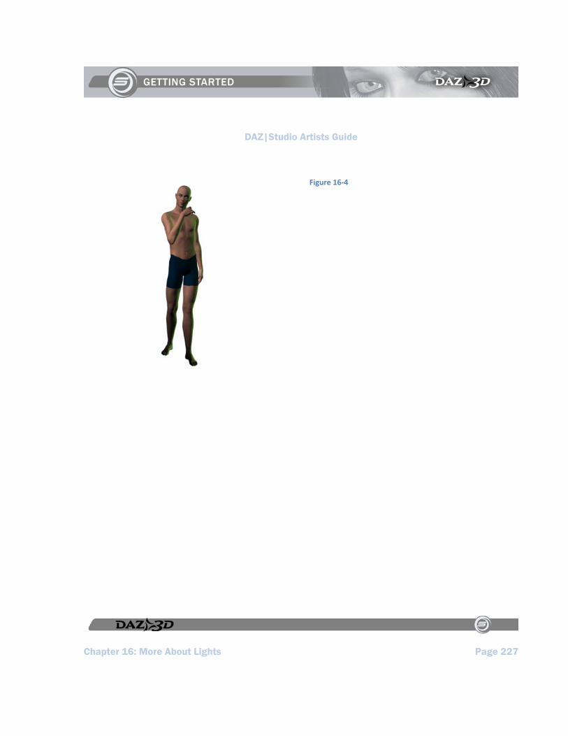
DAZ|Studio Artists Guide
Chapter 16: More About Lights Page 227
Figure 16‐4

DAZ|Studio Artists Guide
Chapter 17: Rendering Page 229
Chapter 17 : Rendering
“The object of art is not to reproduce reality, but to create a reality of the same intensity.” -Alberto Giacometti
As we’ve mentioned elsewhere in this manual, rendering is the act of taking a virtual photograph of your scene. You can do this at any time using any available default view or custom camera. When rendering, DAZ|Studio takes everything in your scene into account, including:
locations of figures and objects. figure poses. light locations, types, and settings such
as type, color, intensity, location, rotation, etc.
surface settings including all colors and maps.
camera location and settings. render settings.
About the DAZ|Studio Renderer
DAZ|Studio uses 3Delight, a fast and powerful RenderMan®-complaint renderer that supports many advanced features such as:
Programmable shaders for surfaces, displacement, lights, volumetrics, and images.
Camera controls such as depth of field and motion blur.
Atmospheric effects Ray tracing
Antialiasing Fully optimized for Windows and Mac
OSX.
Speeding Up Your Renders
When rendering, DAZ|Studio takes the raw information from your scene and passes it through your render settings to the 3Delight or OpenGL rendering engines for the final result. Translating all of the 2D and 3D mapping information into individual pixels requires significant computing resources. The actual amount varies by scene complexity: the more items or custom settings and high resolution components you have in your scene (shadows, reflections, high-resolution textures, etc), the more resources are required and the longer the rendering takes. DAZ|Studio is designed to use your computer’s resources as efficiently as possible and we are constantly looking for ways to achieve even greater performance. That said, your scene and your computer are always the largest factors that affect rendering times.
If your render is taking too long for your comfort, there are several things you can do to optimize performance. In order of preference, these steps include:
Remove some items from your scene. Lights and multiple shadow settings are particularly costly in terms of required computing resources.
Turn off shadows. Shadows require extensive computer resources.
Add RAM to your computer. Your computer uses its hard drive as virtual
DAZ|Studio Artists Guide
Page 230 Chapter 17: Rendering
memory, which behaves like additional RAM and expands the total available memory. The only problem with this is that your hard drive is much slower than your regular memory since the computer must read and write data to the hard drive just like any other file. Adding more RAM reduces the need for virtual memory, which can greatly speed up rendering times. The Macintosh platform is particularly responsive to increases in RAM.
You should check to see if your computer’s RAM is the best fit for your computer’s specifications. Oftentimes even the large manufacturers put in lower-specification RAM to save money. You may be able to simply replace the RAM you have with higher-specification memory and get noticeable improvements (e.g. replacing PC2100 DDR RAM with PC-2700, or PC-3200 and better if you motherboard supports it.)
Upgrade your computer’s CPU if your motherboard can support it. Faster CPUs can process more data in any given amount of time. If your computer has insufficient RAM however, the faster CPU will simply spend more time waiting for information instead of processing the render, which doesn’t do you too much good.
The Render Settings Window
The Render Settings window appears when you select Render > Render Settings. Once you have
made your selections, you have the following options:
To render an image using your current settings, click the Render button
To save your settings without rendering an image, click the Accept button
To exit the window, click the Cancel button
By default, this window contains two tabs: General and Advanced
General Tab
The General tab (Figure 17-1) is where you set the following basic rendering options:
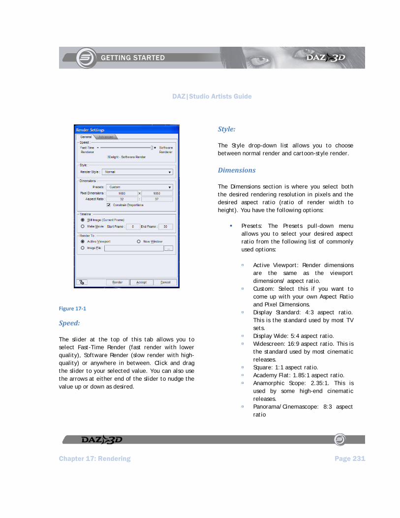
DAZ|Studio Artists Guide
Chapter 17: Rendering Page 231
Figure 17‐1
Speed:
The slider at the top of this tab allows you to select Fast-Time Render (fast render with lower quality), Software Render (slow render with high-quality) or anywhere in between. Click and drag the slider to your selected value. You can also use the arrows at either end of the slider to nudge the value up or down as desired.
Style:
The Style drop-down list allows you to choose between normal render and cartoon-style render.
Dimensions
The Dimensions section is where you select both the desired rendering resolution in pixels and the desired aspect ratio (ratio of render width to height). You have the following options:
Presets: The Presets pull-down menu allows you to select your desired aspect ratio from the following list of commonly used options:
Active Viewport: Render dimensions are the same as the viewport dimensions/ aspect ratio.
Custom: Select this if you want to come up with your own Aspect Ratio and Pixel Dimensions.
Display Standard: 4:3 aspect ratio. This is the standard used by most TV sets.
Display Wide: 5:4 aspect ratio. Widescreen: 16:9 aspect ratio. This is
the standard used by most cinematic releases.
Square: 1:1 aspect ratio. Academy Flat: 1.85:1 aspect ratio. Anamorphic Scope: 2.35:1. This is
used by some high-end cinematic releases.
Panorama/Cinemascope: 8:3 aspect ratio
DAZ|Studio Artists Guide
Page 232 Chapter 17: Rendering
QVTR Panorama: 13:4 aspect ratio Letter (17:22) Legal (17:28) ISO Paper – Portrait (1:1.4142) ISO Paper – Landscape (1.4142:1) Photo/35mm Slide/VistaVision (3:2) Super 8 mm (27:20) 16 mm (18:13) Super 16 mm (5:3) 65mm (11:4) IMAX (10:7) 70mm (46:21) Techniscope (47:20)
Pixel Dimensions: Enter your desired render size (in pixels) in the text fields in width x height format. If you have selected a preset or have Constrain Proportions checked, entering one value will adjust the other value to preserve the selected aspect ratio.
Aspect Ratio: Enter your desired aspect ratio in the fields in width:height format. For example, if you select 4:3, the render will be 4 pixels wide for every 3 pixels high.
Constrain Proportions: Checking the Constrain Proportions checkbox forces the selected aspect ratio to remain identical. Values will automatically adjust to preserve your selected setting. Clearing this checkbox allows you to set any dimensions/ aspect ratio you desire.
Timeline
Options in the Timeline section determine whether you are going to render a still image or an animation.
To render a still image, choose the frame you want to render and check the Still Image (Current Frame) option.
To render an animation, check the Make Movie option, and enter the range of frames that you want to render. The Start Frame field should display the first frame you want to render, and the End Frame field should display the number of the last frame you want to render.
Render To
The Render To options allow you to specify where to output renders. Your available options are:
Active Viewport: Checking the Active Viewport checkbox renders images to the active viewport. Images rendered to the viewport will occupy the height and width of the viewport. If you have an orthogonal camera selected, you will get an orthogonal render. Rendered images will be the same size as the currently active viewport.
New Window: Checking the New Window checkbox will make your renders appear in a separate window.
File: Checking the File checkbox saves rendered images directly to an image file on your hard drive instead of to your

DAZ|Studio Artists Guide
Chapter 17: Rendering Page 233
screen. If this option is selected, you must also select a filename or render to the currently displayed filename. To select a new filename, click the “...” button to open a standard Browse dialog, which allows you to select your desired folder and filename to save the new rendering. Clearing this checkbox disables this option. You can also specify your desired image format. DAZ|Studio supports TIF, PNG, and JPG images.
Advanced Tab
The Advanced tab (Figure 17-2) allows you to specify the following render options:
Figure 17‐2
Preview Render - OpenGL Single Pass (No Shadows): This option uses your the capabilities of your OpenGL video card to quickly render the image without visual cues, such as highlight and shadow. This option is essentially identical to a screen capture of the active viewport. Rendering in this way is much faster but not as realistic. If you experience any issues with OpenGL, try updating your video card drivers with those provided by the manufacturer. Please refer to your video
DAZ|Studio Artists Guide
Page 234 Chapter 17: Rendering
card’s documentation for instructions on how to update the drivers.
Hardware Assisted Render - OpenGL Multi-Pass : This option also utilizes your video card’s OpenGL capabilities to create the final render. OpenGL uses dedicated rendering hardware on your video card to render images. The central processor on a 3D accelerated video card (often known as a Graphics Processing Unit, or “GPU”) is specially designed to render polygons, textures, etc. In other words, it is specifically designed to create images based on everything in your DAZ|Studio scenes. This level of specialization plus your video card’s on-board high-speed RAM (up to 256MB and beyond for the high-end professional cards) makes OpenGL much faster than standard software renders.
Use OpenGL Shader (GLSL): A software render uses an application that instructs your computer’s main CPU how to perform the calculations needed for rendering. This combined with system bottlenecks such as virtual memory and RAM speeds can greatly lengthen the time require to render any given scene. There are two ways to achieve this: With or without DAZ|Studio’s internal OpenGL shader. Without it, you will get a render that runs 8 passes (calculations) per light, and a general render quality. With the OpenGL Shader, you have finer control over how your render is accomplished by specifying how many passes occur per light.
Use Software (3Delight): This option bypasses OpenGL (and the acceleration on your video card) and calculates the render entirely by your computer’s CPU. This type of rendering takes more time, but has the most accuracy and the best results. It is also the only option open to those who are running DAZ|Studio on a card that does not have sufficient OpenGL capabilities. There are three options in this menu:
Bucket Order: Allows you to select the order in which pixels are rendered. Your available options are Horizontal (top to bottom), Vertical (left to right), Spiral (center to corners), Circle (center outwards), and Zig-Zag.
Bucket Size: This allows you to select how much information the renderer will tackle at any one time. You can set the bucket size higher if you have a higher-performance machine with a lot of RAM, which speeds up your renders. If you have less RAM than recommended or want to make DAZ|Studio appear more responsive during a render, lower the bucket size.
Maximum Ray Trace Depth: Lets you determine how many times you want a “ray” to bounce off reflective/refractive surfaces before being discarded for calculation by the render engine. Setting it low will speed up the render time, but lowers the overall accuracy of the results. Raising it above default will increase the accuracy, but will slow down the renderer.
Pixel Samples (X): Coming Soon Pixel Samples (Y): Coming Soon

DAZ|Studio Artists Guide
Chapter 17: Rendering Page 235
Shadow Samples: Coming Soon
Spot Renders
If you want to see how part of your scene will look but don’t want to wait for the whole thing to render, choose Tools > Spot Render, and then click
and drag a rectangle in your active viewport around the area you wish to render. As soon as you release the mouse button, it will render the area you selected.

DAZ|Studio Artists Guide
DAZ|Studio Artists Guide Page 237
Section 6:
Plug‐ins

DAZ|Studio Artists Guide
Chapter 18: Tools, Plug-ins and Scripts Page 239
Chapter 18 : Tools: Plugins and Scripts
“You come to nature with all her theories, and she knocks them all flat.” -Pierre Auguste Renoir
A Word About How DAZ|Studio is Built
Plug-ins and Scripts are additional programs that you can use to expand and enhance DAZ|Studio, beyond what it is capable of by itself. DAZ|Studio was expressly written to be modular in nature, to expand in ways that will meet the needs and desires of both hobbyist and professional. Its internal architecture is built to be flexible for this reason, which make tools an integral part of what DAZ|Studio is.
Why Such a Modular Approach?
Why build a modular architecture, instead of simply building an entire suite of features in one comprehensive package? The answers are varied, but they can be boiled down in this way:
Not everyone wants or needs a potentially huge and expensive suite of features when in many cases a simpler program will do. With a modular approach, DAZ can distribute the core program free of charge, and keep additional features to a lower, more attractive cost.
A modular approach utilizes resources more efficiently by committing system resources only towards those plug-ins that are installed.
A modular approach allows DAZ (as well as independent third-party developers) to isolate and rectify potential bugs and instability more rapidly.
It is easier to learn and master a program one step at a time, and a modular approach isn’t as intimidating to new users as a large suite would be.
It is easier to customize your workflow as an artist or animator with a fast and light set of tools than it would be to use a large ‘one-size-fits-all’ suite.
A modular approach builds a larger sense of community by inviting, encouraging, and assisting third-party development of tools from within the user community. The increased creativity and community participation is beyond measure, and of benefit to all.
What Kind of Tools Are There?
There are three types of tools available for DAZ|Studio: Plug-ins, Scripts, and Stand-Alone Programs.
Plug-ins are compiled C++ programs that rely on DAZ|Studio to function, but operate on their own CPU time and in their own memory space. These are located on your hard drive in <DAZ|Studio root>/plug-ins/, and are recognized by your operating system as dynamic

DAZ|Studio Artists Guide
Page 240 Chapter 18: Tools, Plug-ins and Scripts
libraries ( *.dll in Windows, and *.dylib in Mac OS X.) These tools cannot be activated from outside of DAZ|Studio (and typically rely on a specific version of the SDK.) Plug-ins are the fastest and most efficient of the three tool types, but require C++ and Qt programming knowledge to assemble and implement.
Scripts are text instructions that are interpreted by DAZ|Studio before execution. These are located on your hard drive in <DAZ|Studio root>/scripts/, and are recognized by your operating system as special files read only by DAZ|Studio (they carry the *.ds or *.dsb extension on both platforms.) Scripts are the easiest to create, require scripting knowledge and an understanding of the SDK, but are the least efficient of the three types.
Stand-Alone Programs are independent executable programs. They are designed and compiled to work with DAZ|Studio data, but are not dependent on it in order to run. These can be located almost anywhere on your hard drive, and are activated separately from DAZ|Studio, though they do use modules that interface with and within it. Performance depends on complexity, resource requirements, and the skill of the developer(s) who built it. An example of a Stand-Alone Program would be Bryce 5.5, which is available at the DAZ website. Bryce is a powerful 3d landscape application that can operate independently, or integrate tightly with DAZ|Studio.
Where to Get Tools
Most tools can be purchased or downloaded from the DAZ website, or from other sites, artist communities, and online stores around the Internet. They don’t necessarily have to be standalone compiled plug-ins, either. Again, they can be separate programs, compiled scripts, or library assets that add to and expand the functionality of DAZ|Studio.
What Tools are Included?
DAZ|Studio comes with several tools: Save Filters, Pz3 Importer, PowerPose and D-Form, to name a key few. We will describe them briefly here to show you how tools are used and found within DAZ|Studio. For further information on these tools, please refer to the manuals for each tool.
PowerPose is a tool that simplifies the act of posing a figure within a scene. Easy to learn and easy to put to use, PowerPose greatly speeds up the time required to pose a figure, and allows you to do so in a more intuitive way. It also allows for setting more natural and organic poses to a figure without the need to set each individual bone in a figure. PowerPose is activated by clicking on it in the Tools Toolbar, and will be described in the next chapter.
D-Form is a tool that allows the you to deform an object, either as a whole or in part, in ways the original modeler may have never anticipated. It also allows you to tweak fitted items (such as clothing) so
DAZ|Studio Artists Guide
Chapter 18: Tools, Plug-ins and Scripts Page 241
that they fit even better to the figure they’re attached to. D-Form does this in a way that is intuitive and easy to grasp, and has a highly customizable set of features that can be set for each D-Form object you add to a scene, using little in the way of system resources to do so. D-Form is also compatible with and can import pre-built “Magnets” from E-Frontier’s Poser(R) compositing suite. D-Form is activated by selecting it in the Windows menu (as described below.)
Log onto the DAZ website to see other tools as they are created and made available, or to suggest ideas for new or existing tools.
Using Tools
There are three ways that you can bring up and utilize a tool, depending on how it was built and implemented within DAZ|Studio. Check the documentation for each tool to determine how to activate and use each tool:
Click the DAZ|Studio Windows menu, and select the tool if it is listed in the menu.
Check to see if the tool has added itself to one of the Toolbars, and select it from there, without accessing the tool tab (which may not be necessary with some tools.)
Check to see if the tool has to be called from outside the DAZ|Studio program (if it is built as a stand-alone tool.)


DAZ|Studio Artists Guide
Chapter 19: PowerPose Page 243
Chapter 19 : PowerPose
PowerPose was built with workflow in mind. All too often, when a user composites a scene he is forced position each bone on a figure. This is a tedious process that tends to consume time and patience. While almost any compositing program allows you to drag and position bones on a figure within the viewport window, most are inaccurate. In addition, their processes tend to take just as long as using parameter dials, sliders, or other similar methods.
PowerPose was built to be different, by combining two desirable actions:
The speed of positioning a figure with the mouse directly within a viewport.
The ability to have the figure bend intelligently when manipulating it, while obeying intentional limits.
Some may confuse using PowerPose with traditional Inverse Kinematics (IK). However, it is important to point out that PowerPose takes a different approach. Inverse Kinematics is typically limited in nature and scope, because it causes other bones in a predefined IK chain to rotate and move in response to the part that you directly move. In traditional IK this chain of movement stops at the root bone of the figure. By way of example, when you apply traditional IK to the legs or feet of a figure and then try to move the chest, movement is limited to the bones between the chest and the root bone (typically the Hip). If you
try to move the shin, only the shin and thigh move while the hip and feet remain unchanged.
PowerPose by contrast calculates movement of all bones in a figure between any pinned bones and the bone being moved. With PowerPose, you can pin any bone, and then move all bones between the bone that is pinned and the bone that is dragged, including the figure’s root bone.
The PowerPose Tab
The PowerPose Tab consists of two sub-tabs: Body and Instructions. The latter tab is pretty self-explanatory. Click the Instructions tab to get a brief description of how to use the controls in the Body Tab.
Posing Body Parts
Use the Body Tab (Figure 19-1) to pose the main body parts. When a poseable figure is selected in your scene, the Body Tab displays the shape of a human figure with a series of dots (and sometimes triangles) arranged on it. These dots and triangles represent the parts of the body that you can pose. To pose a part, simply click one of the dots to activate it. The dot “lights up” when it is selected. After you select a part, you simply drag your mouse up, down, left, or right over the dot and you’ll see the body part move in response to your mouse movements.
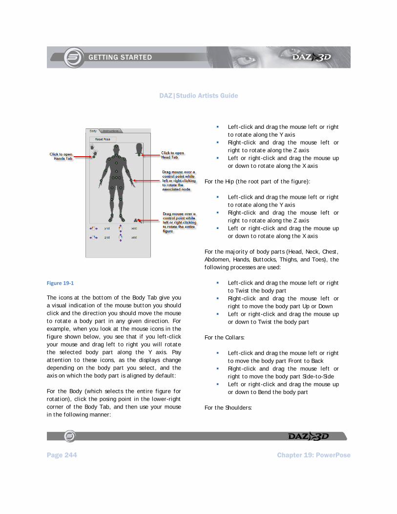
DAZ|Studio Artists Guide
Page 244 Chapter 19: PowerPose
Figure 19‐1
The icons at the bottom of the Body Tab give you a visual indication of the mouse button you should click and the direction you should move the mouse to rotate a body part in any given direction. For example, when you look at the mouse icons in the figure shown below, you see that if you left-click your mouse and drag left to right you will rotate the selected body part along the Y axis. Pay attention to these icons, as the displays change depending on the body part you select, and the axis on which the body part is aligned by default:
For the Body (which selects the entire figure for rotation), click the posing point in the lower-right corner of the Body Tab, and then use your mouse in the following manner:
Left-click and drag the mouse left or right to rotate along the Y axis
Right-click and drag the mouse left or right to rotate along the Z axis
Left or right-click and drag the mouse up or down to rotate along the X axis
For the Hip (the root part of the figure):
Left-click and drag the mouse left or right to rotate along the Y axis
Right-click and drag the mouse left or right to rotate along the Z axis
Left or right-click and drag the mouse up or down to rotate along the X axis
For the majority of body parts (Head, Neck, Chest, Abdomen, Hands, Buttocks, Thighs, and Toes), the following processes are used:
Left-click and drag the mouse left or right to Twist the body part
Right-click and drag the mouse left or right to move the body part Up or Down
Left or right-click and drag the mouse up or down to Twist the body part
For the Collars:
Left-click and drag the mouse left or right to move the body part Front to Back
Right-click and drag the mouse left or right to move the body part Side-to-Side
Left or right-click and drag the mouse up or down to Bend the body part
For the Shoulders:

DAZ|Studio Artists Guide
Chapter 19: PowerPose Page 245
Left-click and drag the mouse left or right to move the body part Front to Back
Right-click and drag the mouse left or right to move Twist the body part
Left or right-click and drag the mouse up or down to Bend the body part
For the Forearms:
Left-click and drag the mouse left or right to Bend the body part
Right-click and drag the mouse left or right to move the body part Side-to-Side
Left or right-click and drag the mouse up or down to Twist the body part
For the Feet:
Left-click and drag the mouse left or right to move the body part Side-to-Side
Right-click and drag the mouse left or right to Twist the body part
Left or right-click and drag the mouse up or down to Bend the body part
When positioning a figure, it is helpful to keep a few things in mind:
Always check your poses from more than one camera angle. Take the time to select another camera and move it around. This ensures that you have the figure right where you want it, and provides a better view of what you’re doing.
You can always Undo one or more actions if things don’t go the way you anticipated, so feel free to experiment.
PowerPose is fairly resource-intensive. You may want to move the mouse more slowly on older systems, as there may be some lag.
You can always use PowerPose to help you get your figure into a rough position, and then fine-tune it later by working with individual bones. Conversely, you can use it to create something natural and unique. The choice is yours.
If you want to start all over again, click the Reset Pose button in any of the PowerPose Tabs to return the figure to its default position. Note that the Reset Pose button
NOTE!
If your figure truly is distorted beyond all recognition, you always have the option of using the Reset Pose button, which appears at the top of the Body, Head, and Hands Tabs. However, keep in mind that the Reset Pose button will return the entire figure to its default position, regardless of the tab it appears in. In other words, the Reset Pose button in the Hands tab does not only reset the hand pose, and the Reset Pose button in the Head tab does not only reset the Head pose. Fortunately, the Edit > Undo command gives you a way back out of the Reset Pose command if you change your mind afterward.
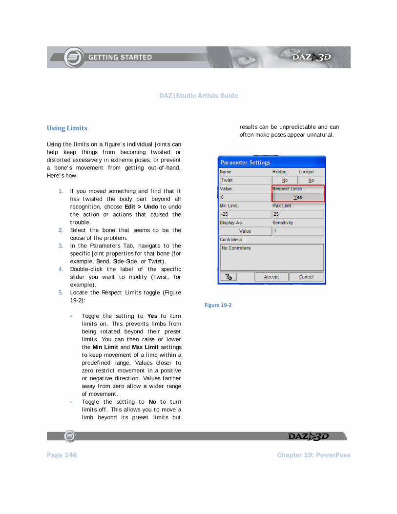
DAZ|Studio Artists Guide
Page 246 Chapter 19: PowerPose
Using Limits
Using the limits on a figure’s individual joints can help keep things from becoming twisted or distorted excessively in extreme poses, or prevent a bone’s movement from getting out-of-hand. Here’s how:
1. If you moved something and find that it has twisted the body part beyond all recognition, choose Edit > Undo to undo the action or actions that caused the trouble.
2. Select the bone that seems to be the cause of the problem.
3. In the Parameters Tab, navigate to the specific joint properties for that bone (for example, Bend, Side-Side, or Twist).
4. Double-click the label of the specific slider you want to modify (Twist, for example).
5. Locate the Respect Limits toggle (Figure 19-2):
Toggle the setting to Yes to turn limits on. This prevents limbs from being rotated beyond their preset limits. You can then raise or lower the Min Limit and Max Limit settings to keep movement of a limb within a predefined range. Values closer to zero restrict movement in a positive or negative direction. Values farther away from zero allow a wider range of movement.
Toggle the setting to No to turn limits off. This allows you to move a limb beyond its preset limits but
results can be unpredictable and can often make poses appear unnatural.
Figure 19‐2

DAZ|Studio Artists Guide
Chapter 19: PowerPose Page 247
TIP!
To prevent distortion and contorting when you pose your figures with PowerPose, it’s best to leave the Respect Limits setting on for each joint of a figure’s three rotational axes (bend, twist, and side-side). If you have limits turned off, keep a very close eye on your movements and perform those movements in small steps. DAZ Original figures have limits pre-built into them. Though it takes time, you can manually set the Min and Max limits on each joint in any figure that does not have them.
Posing Hand Parts
To access the Hands Tab from any of the other tabs, simply click the green dot that appears in one of the corners, near the small hand silhouette. The Hands Tab, shown in Figure 19-3, appears. Dots appear for each finger section as well as for the hand.
Figure 19‐3
When you pose a hand, you’ll probably find it much easier to see what’s happening when you bring the hand and fingers into closer view. For example, if you are trying to position fingers around an object that the hand holds, use the Scene Tab to select all hand parts (hand and all fingers). Then click the Camera Frame control icon in the Viewport/Cameras toolbar to frame all of the selected hand parts into the view of the camera as shown in Figure 19-4. If you are using

DAZ|Studio Artists Guide
Page 248 Chapter 19: PowerPose
multiple views, you’ll need to click the Camera Frame control in each view to focus on the selected parts.
Figure 19‐4
The mouse control icons at the bottom display the axis of rotation for each finger when you click its control point. Briefly, the rotations of the fingers and hand can be summarized as follows:
For the Hand, and for the second and third segments of each finger:
Left-click and drag the mouse left or right to Twist the body part
Right-click and drag the mouse left or right to move the body part Side-to-Side
Left or right-click and drag the mouse up or down to Bend the body part
For Thumb1 (the segment of the thumb that is closest to the hand):
Left-click and drag the mouse left or right to Bend the body part
Right-click and drag the mouse left or right to Twist the body part
Left or right-click and drag the mouse up or down to move the body part Up or Down
For the segments of the remaining fingers that are closest to the hand (Index1, Mid1, Ring1, and Pinky1):
Left-click and drag the mouse left or right to move the body part Side-to-Side
Right-click and drag the mouse left or right to Twist the body part
Left or right-click and drag the mouse up or down to Bend the body part
Posing Head Parts
To access the Head Tab from any of the other tabs, simply click the green dot that appears in one of the corners, near the small head silhouette. The Head Tab, shown in Figure 19-5, appears. Dots appear so that you can pose the head, neck, and eyes.
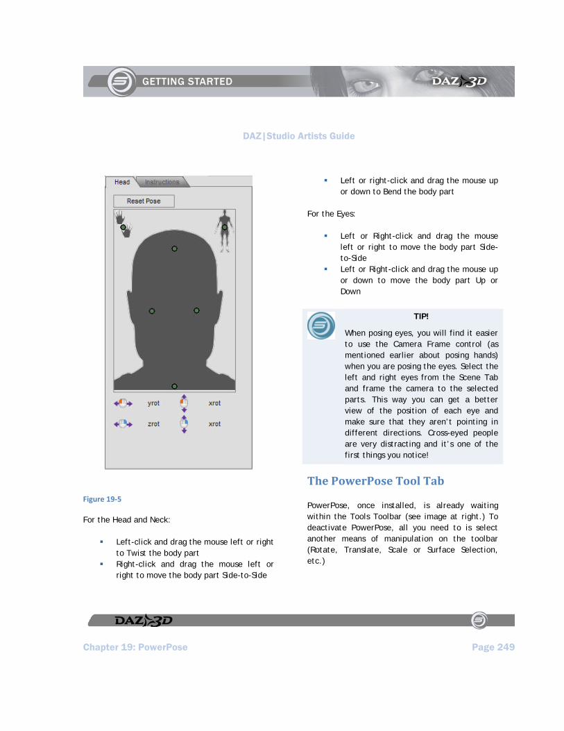
DAZ|Studio Artists Guide
Chapter 19: PowerPose Page 249
Figure 19‐5
For the Head and Neck:
Left-click and drag the mouse left or right to Twist the body part
Right-click and drag the mouse left or right to move the body part Side-to-Side
Left or right-click and drag the mouse up or down to Bend the body part
For the Eyes:
Left or Right-click and drag the mouse left or right to move the body part Side-to-Side
Left or Right-click and drag the mouse up or down to move the body part Up or Down
TIP!
When posing eyes, you will find it easier to use the Camera Frame control (as mentioned earlier about posing hands) when you are posing the eyes. Select the left and right eyes from the Scene Tab and frame the camera to the selected parts. This way you can get a better view of the position of each eye and make sure that they aren’t pointing in different directions. Cross-eyed people are very distracting and it’s one of the first things you notice!
The PowerPose Tool Tab
PowerPose, once installed, is already waiting within the Tools Toolbar (see image at right.) To deactivate PowerPose, all you need to is select another means of manipulation on the toolbar (Rotate, Translate, Scale or Surface Selection, etc.)
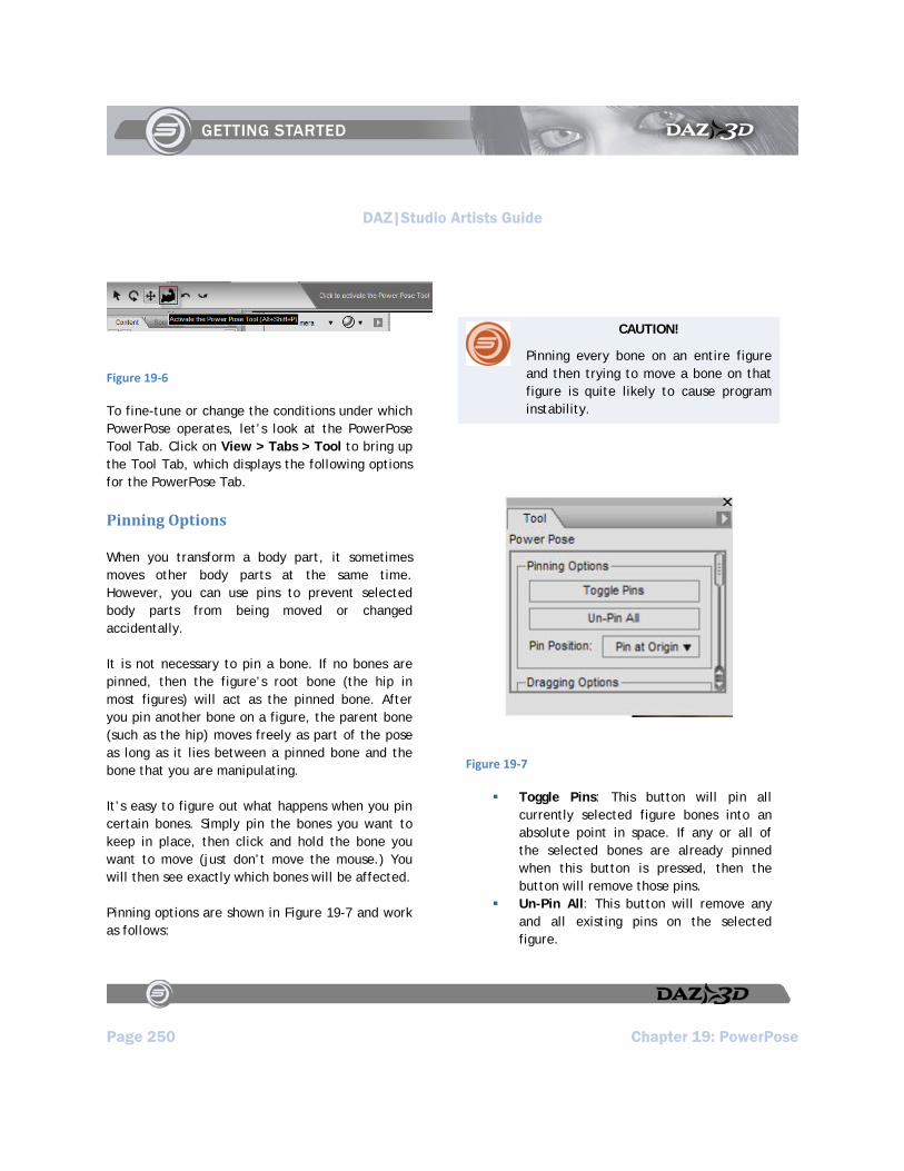
DAZ|Studio Artists Guide
Page 250 Chapter 19: PowerPose
Figure 19‐6
To fine-tune or change the conditions under which PowerPose operates, let’s look at the PowerPose Tool Tab. Click on View > Tabs > Tool to bring up the Tool Tab, which displays the following options for the PowerPose Tab.
Pinning Options
When you transform a body part, it sometimes moves other body parts at the same time. However, you can use pins to prevent selected body parts from being moved or changed accidentally.
It is not necessary to pin a bone. If no bones are pinned, then the figure’s root bone (the hip in most figures) will act as the pinned bone. After you pin another bone on a figure, the parent bone (such as the hip) moves freely as part of the pose as long as it lies between a pinned bone and the bone that you are manipulating.
It’s easy to figure out what happens when you pin certain bones. Simply pin the bones you want to keep in place, then click and hold the bone you want to move (just don’t move the mouse.) You will then see exactly which bones will be affected.
Pinning options are shown in Figure 19-7 and work as follows:
CAUTION!
Pinning every bone on an entire figure and then trying to move a bone on that figure is quite likely to cause program instability.
Figure 19‐7
Toggle Pins: This button will pin all currently selected figure bones into an absolute point in space. If any or all of the selected bones are already pinned when this button is pressed, then the button will remove those pins.
Un-Pin All: This button will remove any and all existing pins on the selected figure.
DAZ|Studio Artists Guide
Chapter 19: PowerPose Page 251
Pin Position: This drop-down menu will allow you to determine the behavior of all pinned bones, by letting you set exactly what part of the pinned bone you want fixed in space. The options are as follows:
Pin at Origin: This option pins the bone at a point that is closest to its parent bone. For example, a shin bone will be fixed at the knee, a foot will be fixed at the ankle, or a forearm will be fixed at the elbow. The pinned bone pivots at the joint closest to its parent. Pinned bones that do not have a parent, such as a hip, will pivot at the center.
Pin at Ends: This option pins the bone at the point that is farthest from its parent bone. For example, a shin bone will be fixed at the ankle, a foot will be fixed at the toes, or a forearm will be fixed at the wrist. The pinned bone pivots at the joint furthest from its parent. Pinned bones with no children (such as fingertips) will pin at their origin if this option is selected. Pinned bones with multiple ends (such as the Hip and Chest) will pin at all ends.
Pin at Both: This option holds both ends of the bone(s) in a fixed position, effectively fixing the entire bone in absolute space. It will not pivot or change position at all in PowerPose unless pushed to extremes
Dragging Options
Drag Position: This sub-menu lets you select which part of a bone will move when you select and drag it around in the viewport, and determine its behavior. This submenu comes with three options:
Drag at Center: This option moves the bone around its center and uses that point to calculate position, no matter where you click and drag the bone.
Drag at Origin: This option moves the bone by the point that is closest to its parent. Bones with no parents (such as a Hip) will be calculated and moved by their centers instead.
Drag at End: This option moves the bone by the point of that bone furthest away from its parent. Bones with multiple ends (such as a Chest or Hip) will be calculated and moved by their centers instead.
Transform Gizmo: This menu allows you to select and place a Transform Gizmo into a scene, which allows for a higher precision in using PowerPose. When you use Transform Gizmos you don’t have to rely as much on moving cameras to check all three dimensions of movement. The Transform Gizmo options are as follows:

DAZ|Studio Artists Guide
Page 252 Chapter 19: PowerPose
Figure 19‐8
None: No Transform Gizmos are used in the scene.
Translate: This option provides a high degree of precision. It behaves just like the regular translate tool. Drag a translate arrow along an axis to move the bone in one direction. Choose one of the small outlined planes emanating from the central cube to drag along any two axes. Select the central cube to translate the bone along all three axes at the same time.
Figure 19‐9
Drawing Options
Drawing Options determine how bones are represented while you drag them. You can choose higher settings to improve the display of objects while you move them, or lower settings to conserve on system resources.
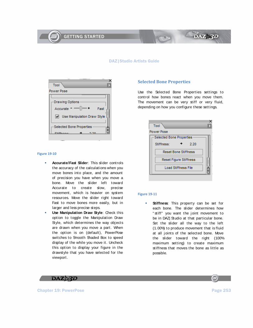
DAZ|Studio Artists Guide
Chapter 19: PowerPose Page 253
Figure 19‐10
Accurate/Fast Slider: This slider controls the accuracy of the calculations when you move bones into place, and the amount of precision you have when you move a bone. Move the slider left toward Accurate to create slow, precise movement, which is heavier on system resources. Move the slider right toward Fast to move bones more easily, but in larger and less precise steps.
Use Manipulation Draw Style: Check this option to toggle the Manipulation Draw Style, which determines the way objects are drawn when you move a part. When the option is on (default), PowerPose switches to Smooth Shaded Box to speed display of the while you move it. Uncheck this option to display your figure in the drawstyle that you have selected for the viewport.
Selected Bone Properties
Use the Selected Bone Properties settings to control how bones react when you move them. The movement can be very stiff or very fluid, depending on how you configure these settings.
Figure 19‐11
Stiffness: This property can be set for each bone. The slider determines how “stiff” you want the joint movement to be in DAZ|Studio at that particular bone. Set the slider all the way to the left (1.00%) to produce movement that is fluid at all joints of the selected bone. Move the slider toward the right (100% maximum setting) to create maximum stiffness that moves the bone as little as possible.

DAZ|Studio Artists Guide
Page 254 Chapter 19: PowerPose
Reset Bone Stiffness: Resets the stiffness settings of the selected bone(s) back to their default values.
Reset Figure Stiffness: Resets the stiffness settings of all bones in the entire figure back to their default values.
Load Stiffness File: Allows you to load a PowerPose data file (.dsx extension) that contains predetermined settings for various figures and body parts. Files are
located in the DAZStudio > plug-ins > PowerPose folder on your hard drive.

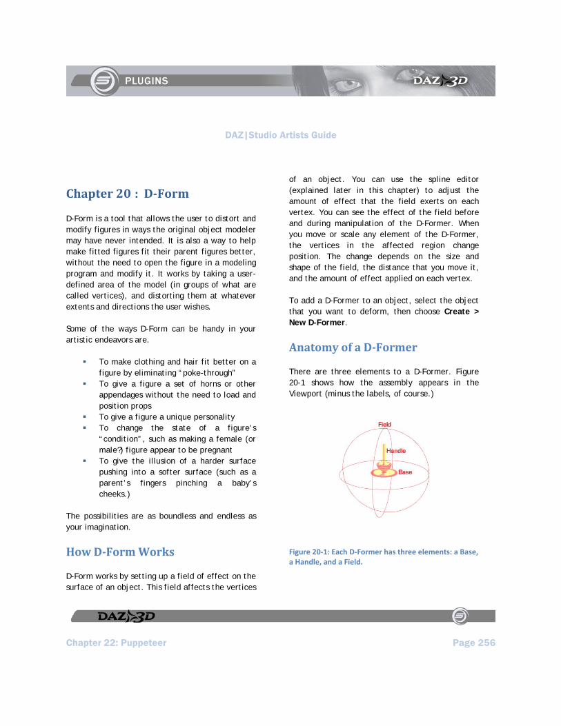
DAZ|Studio Artists Guide
Chapter 22: Puppeteer Page 256
Chapter 20 : DForm
D-Form is a tool that allows the user to distort and modify figures in ways the original object modeler may have never intended. It is also a way to help make fitted figures fit their parent figures better, without the need to open the figure in a modeling program and modify it. It works by taking a user-defined area of the model (in groups of what are called vertices), and distorting them at whatever extents and directions the user wishes.
Some of the ways D-Form can be handy in your artistic endeavors are.
To make clothing and hair fit better on a figure by eliminating “poke-through”
To give a figure a set of horns or other appendages without the need to load and position props
To give a figure a unique personality To change the state of a figure’s
“condition”, such as making a female (or male?) figure appear to be pregnant
To give the illusion of a harder surface pushing into a softer surface (such as a parent’s fingers pinching a baby’s cheeks.)
The possibilities are as boundless and endless as your imagination.
How DForm Works
D-Form works by setting up a field of effect on the surface of an object. This field affects the vertices
of an object. You can use the spline editor (explained later in this chapter) to adjust the amount of effect that the field exerts on each vertex. You can see the effect of the field before and during manipulation of the D-Former. When you move or scale any element of the D-Former, the vertices in the affected region change position. The change depends on the size and shape of the field, the distance that you move it, and the amount of effect applied on each vertex.
To add a D-Former to an object, select the object that you want to deform, then choose Create > New D-Former.
Anatomy of a DFormer
There are three elements to a D-Former. Figure 20-1 shows how the assembly appears in the Viewport (minus the labels, of course.)
Figure 20‐1: Each D‐Former has three elements: a Base, a Handle, and a Field.
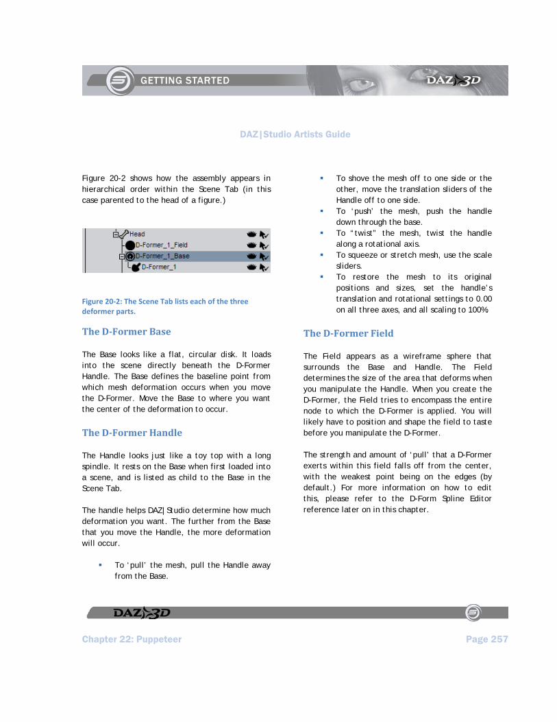
DAZ|Studio Artists Guide
Chapter 22: Puppeteer Page 257
Figure 20-2 shows how the assembly appears in hierarchical order within the Scene Tab (in this case parented to the head of a figure.)
Figure 20‐2: The Scene Tab lists each of the three deformer parts.
The DFormer Base
The Base looks like a flat, circular disk. It loads into the scene directly beneath the D-Former Handle. The Base defines the baseline point from which mesh deformation occurs when you move the D-Former. Move the Base to where you want the center of the deformation to occur.
The DFormer Handle
The Handle looks just like a toy top with a long spindle. It rests on the Base when first loaded into a scene, and is listed as child to the Base in the Scene Tab.
The handle helps DAZ|Studio determine how much deformation you want. The further from the Base that you move the Handle, the more deformation will occur.
To ‘pull’ the mesh, pull the Handle away from the Base.
To shove the mesh off to one side or the other, move the translation sliders of the Handle off to one side.
To ‘push’ the mesh, push the handle down through the base.
To “twist” the mesh, twist the handle along a rotational axis.
To squeeze or stretch mesh, use the scale sliders.
To restore the mesh to its original positions and sizes, set the handle’s translation and rotational settings to 0.00 on all three axes, and all scaling to 100%.
The DFormer Field
The Field appears as a wireframe sphere that surrounds the Base and Handle. The Field determines the size of the area that deforms when you manipulate the Handle. When you create the D-Former, the Field tries to encompass the entire node to which the D-Former is applied. You will likely have to position and shape the field to taste before you manipulate the D-Former.
The strength and amount of ‘pull’ that a D-Former exerts within this field falls off from the center, with the weakest point being on the edges (by default.) For more information on how to edit this, please refer to the D-Form Spline Editor reference later on in this chapter.
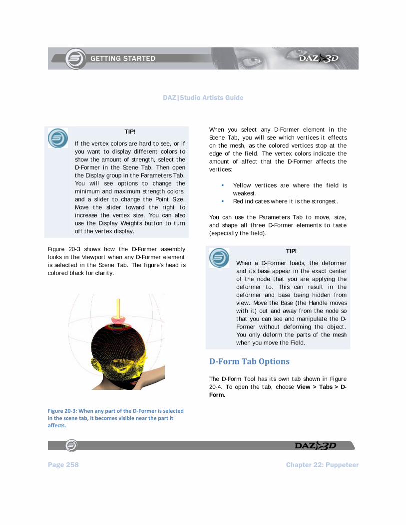
DAZ|Studio Artists Guide
Page 258 Chapter 22: Puppeteer
TIP!
If the vertex colors are hard to see, or if you want to display different colors to show the amount of strength, select the D-Former in the Scene Tab. Then open the Display group in the Parameters Tab. You will see options to change the minimum and maximum strength colors, and a slider to change the Point Size. Move the slider toward the right to increase the vertex size. You can also use the Display Weights button to turn off the vertex display.
Figure 20-3 shows how the D-Former assembly looks in the Viewport when any D-Former element is selected in the Scene Tab. The figure's head is colored black for clarity.
Figure 20‐3: When any part of the D‐Former is selected in the scene tab, it becomes visible near the part it affects.
When you select any D-Former element in the Scene Tab, you will see which vertices it effects on the mesh, as the colored vertices stop at the edge of the field. The vertex colors indicate the amount of affect that the D-Former affects the vertices:
Yellow vertices are where the field is weakest.
Red indicates where it is the strongest.
You can use the Parameters Tab to move, size, and shape all three D-Former elements to taste (especially the field).
TIP!
When a D-Former loads, the deformer and its base appear in the exact center of the node that you are applying the deformer to. This can result in the deformer and base being hidden from view. Move the Base (the Handle moves with it) out and away from the node so that you can see and manipulate the D-Former without deforming the object. You only deform the parts of the mesh when you move the Field.
DForm Tab Options
The D-Form Tool has its own tab shown in Figure 20-4. To open the tab, choose View > Tabs > D-Form.
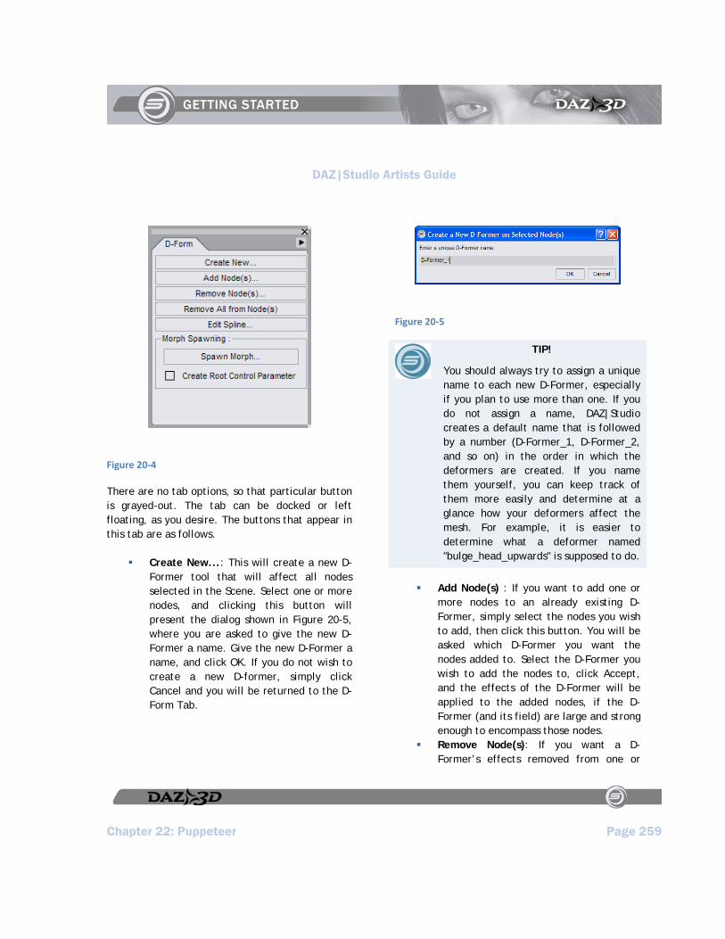
DAZ|Studio Artists Guide
Chapter 22: Puppeteer Page 259
Figure 20‐4
There are no tab options, so that particular button is grayed-out. The tab can be docked or left floating, as you desire. The buttons that appear in this tab are as follows.
Create New...: This will create a new D-Former tool that will affect all nodes selected in the Scene. Select one or more nodes, and clicking this button will present the dialog shown in Figure 20-5, where you are asked to give the new D-Former a name. Give the new D-Former a name, and click OK. If you do not wish to create a new D-former, simply click Cancel and you will be returned to the D-Form Tab.
Figure 20‐5
TIP!
You should always try to assign a unique name to each new D-Former, especially if you plan to use more than one. If you do not assign a name, DAZ|Studio creates a default name that is followed by a number (D-Former_1, D-Former_2, and so on) in the order in which the deformers are created. If you name them yourself, you can keep track of them more easily and determine at a glance how your deformers affect the mesh. For example, it is easier to determine what a deformer named "bulge_head_upwards" is supposed to do.
Add Node(s) : If you want to add one or more nodes to an already existing D-Former, simply select the nodes you wish to add, then click this button. You will be asked which D-Former you want the nodes added to. Select the D-Former you wish to add the nodes to, click Accept, and the effects of the D-Former will be applied to the added nodes, if the D-Former (and its field) are large and strong enough to encompass those nodes.
Remove Node(s): If you want a D-Former’s effects removed from one or

DAZ|Studio Artists Guide
Page 260 Chapter 22: Puppeteer
more nodes, select those nodes in the Scene and then select this button. You will be asked which D-Former you wish removed from the selected nodes (even if there is only one D-Former, in which case only one will be displayed.) The effects of the D-Former will then be removed from those nodes. If there are no nodes left for the D-Former to effect, it will remain parented to the node it is currently parented to, but will not affect it whatsoever. Note that this will not delete the D-Former itself - you’ll have to do that manually.
Remove All From Node(s): This option allows you to remove all D-Former effects from one or more selected nodes. Select which nodes you want to clear, then select this option to clear all D-Former effects from the selected node(s). Note that this will not delete the D-Formers.
Edit Spline... : This opens the D-Form Spline Editor for the selected D-Former Field. Select a D-Former Field you wish to edit, and select this option. Full details on how to use the Spline Editor are explored in the next part of this chapter.
Spawn Morph... : Once you are done deforming the node(s) with one or more D-Formers, this option will create a Morph in the selected node(s)’ mesh, which will then be listed in the Parameters Tab for each node selected. At this point the D-Formers are no longer necessary to create these deformations in the node(s)’ mesh, and can be deleted or removed from the node(s). Be sure to save the figure (preferably under a new
name from the one you loaded) if you want to keep the new morph permanently.
Create Root Control Parameter: This option allows you to save the D-Former effects as a Morph for the entire figure, instead of one or more nodes. The resulting Morph will appear as a slider in the Parameters Tab when the root node of the figure is selected. Select this option if you want your work to be saved as an overall Morph for the figure’s entire mesh.
The DForm Spline Editor
The D-Former by default will apply it’s strongest ‘pull’ at the center of the D-Former’s Field, fading off gradually towards the edges of the field, wherever the mesh lies within that field. However, you can alter that behavior, and how much strength is applied to all points of the mesh from the center of the field outward. This is done by clicking on the Edit Spline... option within the Scene Tab.
Before we detail how to work within the Spline Editor (Figure 20-6), a bit of concept will familiarize you with what a spline is and how it works. If you are already familiar with splines, you can safely skip the next part and get to the inner workings of the editor itself. For those who are not familiar with splines, the sections that follow will likely be of use to you.
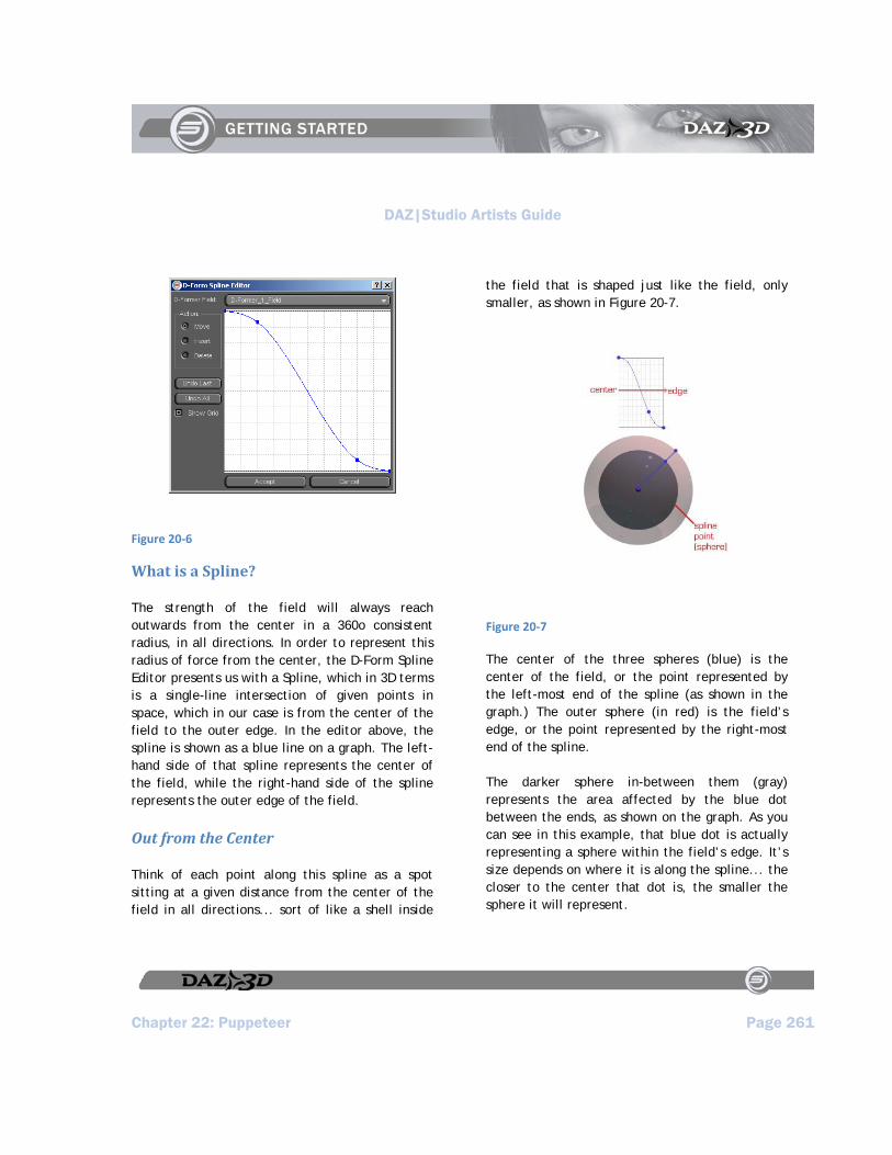
DAZ|Studio Artists Guide
Chapter 22: Puppeteer Page 261
Figure 20‐6
What is a Spline?
The strength of the field will always reach outwards from the center in a 360o consistent radius, in all directions. In order to represent this radius of force from the center, the D-Form Spline Editor presents us with a Spline, which in 3D terms is a single-line intersection of given points in space, which in our case is from the center of the field to the outer edge. In the editor above, the spline is shown as a blue line on a graph. The left-hand side of that spline represents the center of the field, while the right-hand side of the spline represents the outer edge of the field.
Out from the Center
Think of each point along this spline as a spot sitting at a given distance from the center of the field in all directions... sort of like a shell inside
the field that is shaped just like the field, only smaller, as shown in Figure 20-7.
Figure 20‐7
The center of the three spheres (blue) is the center of the field, or the point represented by the left-most end of the spline (as shown in the graph.) The outer sphere (in red) is the field’s edge, or the point represented by the right-most end of the spline.
The darker sphere in-between them (gray) represents the area affected by the blue dot between the ends, as shown on the graph. As you can see in this example, that blue dot is actually representing a sphere within the field’s edge. It’s size depends on where it is along the spline... the closer to the center that dot is, the smaller the sphere it will represent.
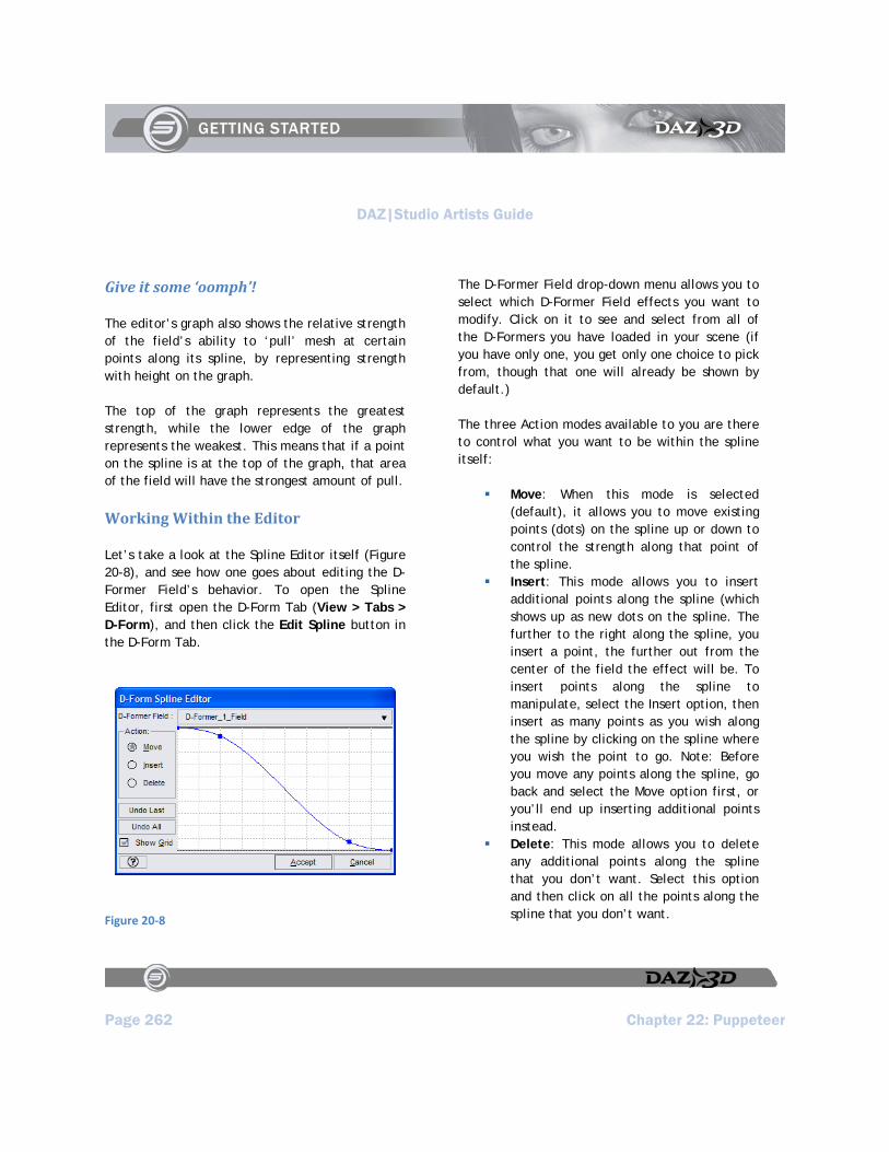
DAZ|Studio Artists Guide
Page 262 Chapter 22: Puppeteer
Give it some ‘oomph’!
The editor’s graph also shows the relative strength of the field’s ability to ‘pull’ mesh at certain points along its spline, by representing strength with height on the graph.
The top of the graph represents the greatest strength, while the lower edge of the graph represents the weakest. This means that if a point on the spline is at the top of the graph, that area of the field will have the strongest amount of pull.
Working Within the Editor
Let’s take a look at the Spline Editor itself (Figure 20-8), and see how one goes about editing the D-Former Field’s behavior. To open the Spline Editor, first open the D-Form Tab (View > Tabs > D-Form), and then click the Edit Spline button in the D-Form Tab.
Figure 20‐8
The D-Former Field drop-down menu allows you to select which D-Former Field effects you want to modify. Click on it to see and select from all of the D-Formers you have loaded in your scene (if you have only one, you get only one choice to pick from, though that one will already be shown by default.)
The three Action modes available to you are there to control what you want to be within the spline itself:
Move: When this mode is selected (default), it allows you to move existing points (dots) on the spline up or down to control the strength along that point of the spline.
Insert: This mode allows you to insert additional points along the spline (which shows up as new dots on the spline. The further to the right along the spline, you insert a point, the further out from the center of the field the effect will be. To insert points along the spline to manipulate, select the Insert option, then insert as many points as you wish along the spline by clicking on the spline where you wish the point to go. Note: Before you move any points along the spline, go back and select the Move option first, or you’ll end up inserting additional points instead.
Delete: This mode allows you to delete any additional points along the spline that you don’t want. Select this option and then click on all the points along the spline that you don’t want.
DAZ|Studio Artists Guide
Chapter 22: Puppeteer Page 263
TIP!
Something to keep in mind is that as you delete a point along the spline: The spline will try to compensate for the missing point by re-drawing itself in a smooth curve between the two points that surround the now-missing point.
TIP!
Before you manipulate or move any other point, be sure to select the Move checkbox before you do, else you may accidentally delete points along the spline that you didn’t want to.
Undo Last allows you to fix a mistake when editing the spline. Simply click the button to undo the last thing you did to the spline.
Undo All resets the entire spline to its default curve. If you become completely lost or turned-around when editing the spline, click this button to get a smooth curve once again. Note that all points along the spline (except the two default points) will also be removed.
Show Grid will toggle on and off the background grid on the graph. The grid represents no real numerical value, but rather they are relative divisions in space that you can use as a convenient reference. If it gets in your way, use this option to shut the grid off.
The Graph itself is where all the action is. To manipulate it, you simply add points to the spline (or use the two default points supplied), and move
them up and down to increase or decrease strength of effect, respectively. Note that you have to add a point to the very spot on the spline where you want the effect to take place - you cannot move points left or right along the spline. The points only move up or down. As you manipulate the spline, keep an eye on the Viewport and look at the colors change on the affected vertices as you change each point. Vertices will turn red as strength increases, or yellow as it decreases along any given vertex. (Move the editor window out of the way if you can’t see the Viewport.)
When you’re done editing the spline, there are the Accept and Cancel buttons. Depending on which button you select, your changes to the spline will be applied to the Field (Accept) and the editor will exit, or ignored and not applied to the field (Cancel), then the editor will exit.
Tutorial: Creating a Head Morph
Let’s begin by doing something simple and relatively useful with the D-Former. We’ll start by taking a default figure and giving it a horn. This will require a single D-Former, and is fairly simple to perform, but it will give you an idea as to how to use this rather powerful tool in an easy way.
First, load a figure into an empty scene. Make sure it has no hair, since we’re working on the head (the hair will only get in the way.) Clothes and other accessories are up to you, though if your computer isn’t very robust, you’ll find that loading just the figure will make things easier on your

DAZ|Studio Artists Guide
Page 264 Chapter 22: Puppeteer
system resources. In our example, we are using the Aiko 3 LE figure shown in Figure 20-9.
Figure 20‐9
Now select her head in the Scene Tab, and use the Frame and Rotate controls (in the viewport and camera controls) to get a good close look at her forehead. With her head selected, choose View > Tabs > D-Form to open the D-Form Tab. Dock it or leave it floating as you desire.
Then, click on Create New and name this new D-Former “Horn” as shown in Figure 20-10. Click OK to create the D-Former.
Figure 20‐10
You’ll see the new D-Former appear, with the field encircling the head, but the Base and Handle hidden inside the head (at the Field’s center.)
Obviously, it’s going to be pretty hard to manipulate the D-Former while the Handle and Base are buried or half-buried inside the figure’s head (as seen in Aiko’s case), so let’s bring them out to where we can see them.
Select the Horn_Base (our D-Former base) in the Scene Tab (it will be a child of the head node), and move it out to a place where you can comfortably see it. An X Translate setting of around 17 should be fine. Adjust the camera as necessary, to achieve results similar to that shown in Figure 20-11.
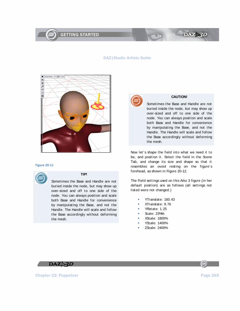
DAZ|Studio Artists Guide
Chapter 22: Puppeteer Page 265
Figure 20‐11
TIP!
Sometimes the Base and Handle are not buried inside the node, but may show up over-sized and off to one side of the node. You can always position and scale both Base and Handle for convenience by manipulating the Base, and not the Handle. The Handle will scale and follow the Base accordingly without deforming the mesh.
CAUTION!
Sometimes the Base and Handle are not buried inside the node, but may show up over-sized and off to one side of the node. You can always position and scale both Base and Handle for convenience by manipulating the Base, and not the Handle. The Handle will scale and follow the Base accordingly without deforming the mesh.
Now let’s shape the field into what we need it to be, and position it. Select the field in the Scene Tab, and change its size and shape so that it resembles an ovoid resting on the figure’s forehead, as shown in Figure 20-12.
The Field settings used on this Aiko 3 figure (in her default position) are as follows (all settings not listed were not changed.)
YTranslate: 160.43 XTranslate: 9.76 YRotate: 1.25 Scale: 23%% XScale: 1800% YScale: 1400% ZScale: 2400%
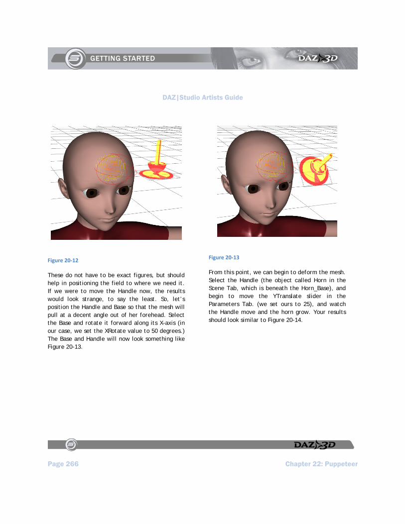
DAZ|Studio Artists Guide
Page 266 Chapter 22: Puppeteer
Figure 20‐12
These do not have to be exact figures, but should help in positioning the field to where we need it. If we were to move the Handle now, the results would look strange, to say the least. So, let’s position the Handle and Base so that the mesh will pull at a decent angle out of her forehead. Select the Base and rotate it forward along its X-axis (in our case, we set the XRotate value to 50 degrees.) The Base and Handle will now look something like Figure 20-13.
Figure 20‐13
From this point, we can begin to deform the mesh. Select the Handle (the object called Horn in the Scene Tab, which is beneath the Horn_Base), and begin to move the YTranslate slider in the Parameters Tab. (we set ours to 25), and watch the Handle move and the horn grow. Your results should look similar to Figure 20-14.
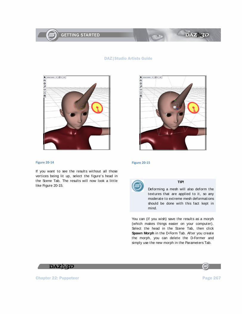
DAZ|Studio Artists Guide
Chapter 22: Puppeteer Page 267
Figure 20‐14
If you want to see the results without all those vertices being lit up, select the figure’s head in the Scene Tab. The results will now look a little like Figure 20-15.
Figure 20‐15
TIP!
Deforming a mesh will also deform the textures that are applied to it, so any moderate to extreme mesh deformations should be done with this fact kept in mind.
You can (if you wish) save the results as a morph (which makes things easier on your computer). Select the head in the Scene Tab, then click Spawn Morph in the D-Form Tab. After you create the morph, you can delete the D-Former and simply use the new morph in the Parameters Tab.

DAZ|Studio Artists Guide
Page 268 Chapter 22: Puppeteer
TIP!
When it comes to multiple D-Formers in a scene: The more D-Formers you add to a scene, the more resources your computer is going to require. It is usually preferable to save each as a morph and then delete the D-Former if you’re only using one D-Former to create the morph. When handling multiple D-Formers in one scene, it will also be easier to manipulate them if you shut off visibility on each D-Former as you finish positioning it. You can do this by selecting the D-Former elements and shutting off visibility on each in the Parameters Tab, or you can do this more easily by clicking the small eyeball icons to the right of each element within the Scene Tab.
Experiment!
Try adding lots of other D-Former built horns (or other parts) to the figure’s head (Figure 20-16), and see what you can come up with.. Just make sure the figure doesn’t lose her patience or sense of humor about it.
Figure 20‐16
TIP!
Try adding D-Formers to already-deformed parts of a node for new and interesting results.
Tutorial: A Coronation of One
We’ve used D-Formers to create a horn or two on the figure’s head, but D-Formers can also act in more subtle and efficient ways. For instance, in this tutorial, we’re going to use only one D-Former to create a “crown” of sorts on our figure’s head. We’ll do this by using the Spline Editor, and by tweaking both it and the D-Former in real time to achieve the results we want.
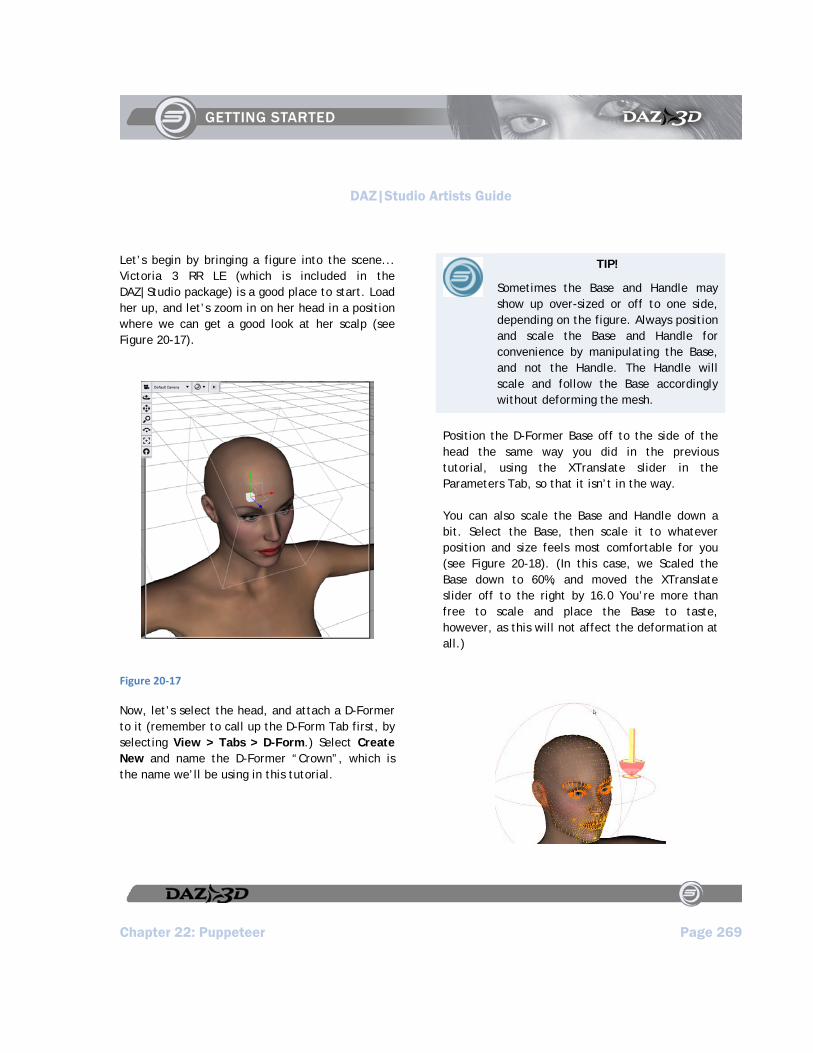
DAZ|Studio Artists Guide
Chapter 22: Puppeteer Page 269
Let’s begin by bringing a figure into the scene... Victoria 3 RR LE (which is included in the DAZ|Studio package) is a good place to start. Load her up, and let’s zoom in on her head in a position where we can get a good look at her scalp (see Figure 20-17).
Figure 20‐17
Now, let’s select the head, and attach a D-Former to it (remember to call up the D-Form Tab first, by selecting View > Tabs > D-Form.) Select Create New and name the D-Former “Crown”, which is the name we’ll be using in this tutorial.
TIP!
Sometimes the Base and Handle may show up over-sized or off to one side, depending on the figure. Always position and scale the Base and Handle for convenience by manipulating the Base, and not the Handle. The Handle will scale and follow the Base accordingly without deforming the mesh.
Position the D-Former Base off to the side of the head the same way you did in the previous tutorial, using the XTranslate slider in the Parameters Tab, so that it isn’t in the way.
You can also scale the Base and Handle down a bit. Select the Base, then scale it to whatever position and size feels most comfortable for you (see Figure 20-18). (In this case, we Scaled the Base down to 60%, and moved the XTranslate slider off to the right by 16.0 You’re more than free to scale and place the Base to taste, however, as this will not affect the deformation at all.)
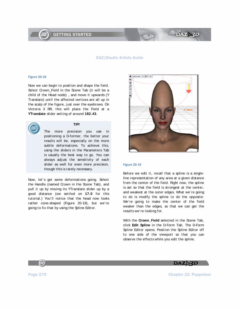
DAZ|Studio Artists Guide
Page 270 Chapter 22: Puppeteer
Figure 20‐18
Now we can begin to position and shape the field. Select Crown_Field in the Scene Tab (it will be a child of the Head node) , and move it upwards (Y Translate) until the affected vertices are all up in the scalp of the figure, just over the eyebrows. On Victoria 3 RR, this will place the Field at a YTranslate slider setting of around 182.43.
TIP!
The more precision you use in positioning a D-former, the better your results will be, especially on the more subtle deformations. To achieve this, using the sliders in the Parameters Tab is usually the best way to go. You can always adjust the sensitivity of each slider as well for even more precision, though this is rarely necessary.
Now, let’s get some deformations going. Select the Handle (named Crown in the Scene Tab), and pull it up by moving its YTranslate slider up by a good distance (we settled on 17.0 for this tutorial.) You’ll notice that the head now looks rather cone-shaped (Figure 20-19), but we’re going to fix that by using the Spline Editor.
Figure 20‐19
Before we edit it, recall that a spline is a single-line representation of any area at a given distance from the center of the field. Right now, the spline is set so that the field is strongest at the center, and weakest at the outer edges. What we’re going to do is modify the spline to do the opposite: We’re going to make the center of the field weaker than the edges, so that we can get the results we’re looking for.
With the Crown_Field selected in the Scene Tab, click Edit Spline in the D-Form Tab. The D-Form Spline Editor opens. Position the Spline Editor off to one side of the viewport so that you can observe the effects while you edit the spline.

DAZ|Studio Artists Guide
Chapter 22: Puppeteer Page 271
Within the Spline Editor, verify that Crown_Field is selected in the D-Former Field drop-down menu. It should already be there by default since it is part of the only D-Former in the scene. Also, verify that the Action is set to Move.
Since there are already two points along the spline that we can manipulate, we’ll use those first. Select each point in turn and move the higher one down, and the lower one upwards, so that the spline looks a lot like Figure 20-20.
Figure 20‐20
You’ll also notice that our head has now deformed accordingly (the Viewport updates each time you move and release a point.) It looks more like what we want to achieve, but it needs a bit more tweaking.
We’ve moved the two points on the spline as much as we can at the moment, so let’s add more points
and manipulate those. In the left side of the Spline Editor, switch to the Insert Action mode. Click once directly on the spline at a point in between the two points already there.
TIP!
If you have a hard time seeing the points on the spline, you can always make the Spline Editor window larger, which will also magnify the points along the spline and make them easier to see.
Now, switch back to the Move Action mode and move that new point down a bit. You’ll see two things: the rim of our “crown” will square itself off a bit more, and a slight depression is created in the center of it. The spline will now look a bit like Figure 20-21.
Figure 20‐21
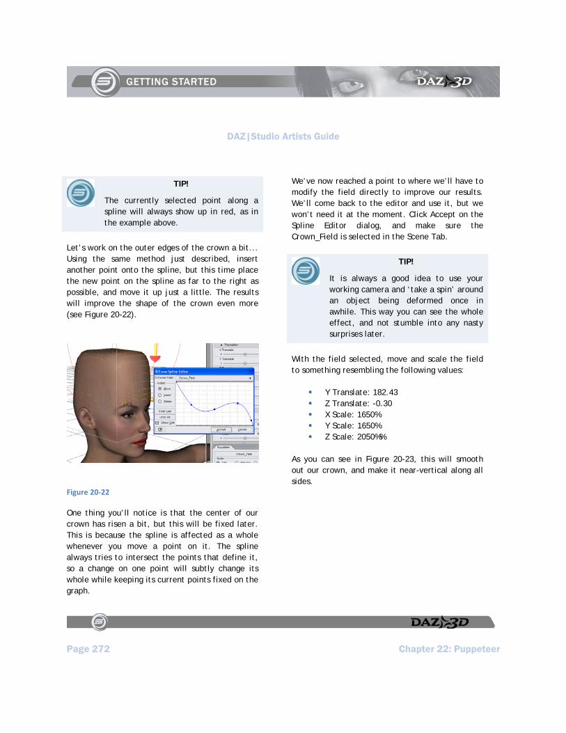
DAZ|Studio Artists Guide
Page 272 Chapter 22: Puppeteer
TIP!
The currently selected point along a spline will always show up in red, as in the example above.
Let’s work on the outer edges of the crown a bit... Using the same method just described, insert another point onto the spline, but this time place the new point on the spline as far to the right as possible, and move it up just a little. The results will improve the shape of the crown even more (see Figure 20-22).
Figure 20‐22
One thing you’ll notice is that the center of our crown has risen a bit, but this will be fixed later. This is because the spline is affected as a whole whenever you move a point on it. The spline always tries to intersect the points that define it, so a change on one point will subtly change its whole while keeping its current points fixed on the graph.
We’ve now reached a point to where we’ll have to modify the field directly to improve our results. We’ll come back to the editor and use it, but we won’t need it at the moment. Click Accept on the Spline Editor dialog, and make sure the Crown_Field is selected in the Scene Tab.
TIP!
It is always a good idea to use your working camera and ‘take a spin’ around an object being deformed once in awhile. This way you can see the whole effect, and not stumble into any nasty surprises later.
With the field selected, move and scale the field to something resembling the following values:
Y Translate: 182.43 Z Translate: -0.30 X Scale: 1650% Y Scale: 1650% Z Scale: 2050%%
As you can see in Figure 20-23, this will smooth out our crown, and make it near-vertical along all sides.

DAZ|Studio Artists Guide
Chapter 22: Puppeteer Page 273
Figure 20‐23
Now let’s open up the Spline Editor again, and do something about the top. In the spline editor, Insert a new point between the two points towards the left of the spline, then Move it and its neighboring points as shown in Figure 20-24. Exit the Spline Editor by clicking Accept.
Figure 20‐24
Let’s put in a bit of a depression in the center of it. In the Scene Tab, select the D-Former Handle (it will be named Crown.) Adjust the Handle a bit (we used the Y Translate slider to bring it up to 14), and notice in Figure 20-25 how we have a decent-looking crown now.
Test-render the results.

DAZ|Studio Artists Guide
Page 274 Chapter 22: Puppeteer
Figure 20‐25
Now all we need do is save the results as a morph on the figure. If you want to keep this morph, be sure to save the figure as well.
Select Victoria’s Head in the Scene Tab. Then from the D-Form Tab, select Spawn Morph. You will be prompted to give the new morph a name (call it CrownHead), and select OK. The new morph appears in the Parameters Tab near the bottom of the morph list. You may have to scroll a bit on complex nodes such as the head.
You can now delete the D-Former, and your morph will be safe. If you want to keep the morph, save the figure under a separate name.
Now all that remains is to create a render using our new morph. All we did to create the final image in Figure 20-26 was the following: Pose the figure. Give her skin, lips, and pupils a greenish tint (by changing the Diffuse Color of these surfaces to a light bluish-green in the Surfaces Tab.) Finally, create a small green-patterned backdrop in any image editor. Import that into the scene, then render the scene using the default light.
Figure 20‐26

DAZ|Studio Artists Guide
Chapter 22: Puppeteer Page 275

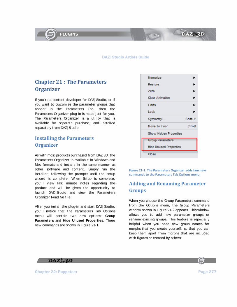
DAZ|Studio Artists Guide
Chapter 22: Puppeteer Page 277
Chapter 21 : The Parameters Organizer
If you’re a content developer for DAZ|Studio, or if you want to customize the parameter groups that appear in the Parameters Tab, then the Parameters Organizer plug-in is made just for you. The Parameters Organizer is a utility that is available for separate purchase, and installed separately from DAZ|Studio.
Installing the Parameters Organizer
As with most products purchased from DAZ 3D, the Parameters Organizer is available in Windows and Mac formats and installs in the same manner as other software and content. Simply run the installer, following the prompts until the setup wizard is complete. When Setup is complete, you’ll view last minute notes regarding the product and will be given the opportunity to launch DAZ|Studio and view the Parameters Organizer Read Me file.
After you install the plug-in and start DAZ|Studio, you’ll notice that the Parameters Tab Options menu will contain two new options: Group Parameters and Hide Unused Properties. These new commands are shown in Figure 21-1.
Figure 21‐1: The Parameters Organizer adds two new commands to the Parameters Tab Options menu.
Adding and Renaming Parameter Groups
When you choose the Group Parameters command from the Options menu, the Group Parameters window shown in Figure 21-2 appears. This window allows you to add new parameter groups or rename existing groups. This feature is especially helpful when you need new group names for morphs that you create yourself, so that you can keep them apart from morphs that are included with figures or created by others.

DAZ|Studio Artists Guide
Page 278 Chapter 22: Puppeteer
Figure 21‐2: The Group Parameters dialog allows you to add and rename parameter groups.
Options in this dialog are:
Add New Group: Allows you to add a new sub-group beneath the Morphs,
General, or Misc parameter group names. Select the group you want to create a subgroup for, then click the Add New Group button. This opens the New Group dialog, where you can assign a name for your new parameter sub-group.
Rename Selected Item: Allows you to rename your subgroups, or any parameter dial that appears in the Group Parameters tab. You can also click to select the item you want to rename, and then click again to rename it.
What’s This Help: Click for interactive help on the features in the Add New Group dialog.
Accept: Click to accept your changes and exit the Group Parameters dialog.
Cancel: Click to exit the Group Parameters dialog without saving your changes.
Options Menu: The Options menu appears when you click the arrow in the upper-right corner. It contains one command, Hide “General” Parameter Group, which hides the display of the Bend, Translate, Rotate, Scale, Visible, Selectable, and Cast Shadows parameter dials. Choose this command to toggle the display of this group on or off.
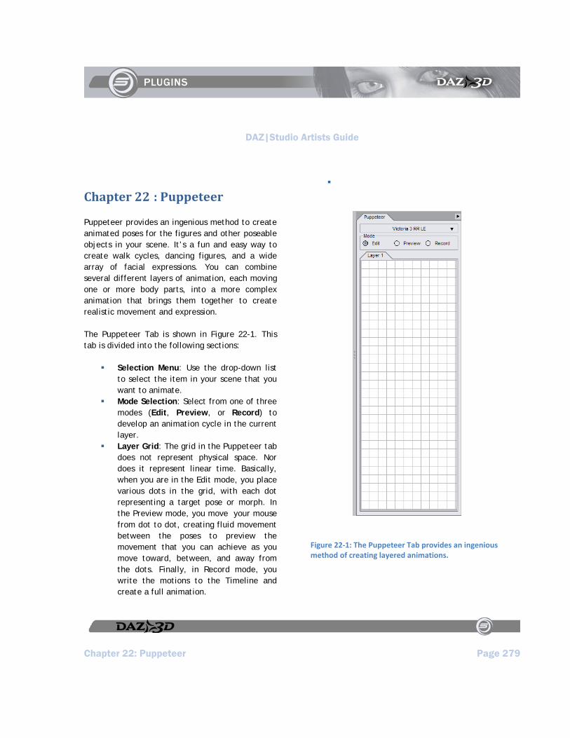
DAZ|Studio Artists Guide
Chapter 22: Puppeteer Page 279
Chapter 22 : Puppeteer
Puppeteer provides an ingenious method to create animated poses for the figures and other poseable objects in your scene. It’s a fun and easy way to create walk cycles, dancing figures, and a wide array of facial expressions. You can combine several different layers of animation, each moving one or more body parts, into a more complex animation that brings them together to create realistic movement and expression.
The Puppeteer Tab is shown in Figure 22-1. This tab is divided into the following sections:
Selection Menu: Use the drop-down list to select the item in your scene that you want to animate.
Mode Selection: Select from one of three modes (Edit, Preview, or Record) to develop an animation cycle in the current layer.
Layer Grid: The grid in the Puppeteer tab does not represent physical space. Nor does it represent linear time. Basically, when you are in the Edit mode, you place various dots in the grid, with each dot representing a target pose or morph. In the Preview mode, you move your mouse from dot to dot, creating fluid movement between the poses to preview the movement that you can achieve as you move toward, between, and away from the dots. Finally, in Record mode, you write the motions to the Timeline and create a full animation.
Figure 22‐1: The Puppeteer Tab provides an ingenious method of creating layered animations.
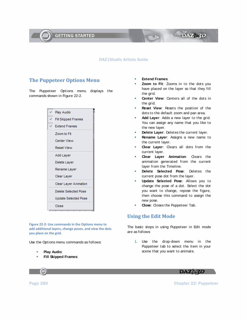
DAZ|Studio Artists Guide
Page 280 Chapter 22: Puppeteer
The Puppeteer Options Menu
The Puppeteer Options menu displays the commands shown in Figure 22-2.
Figure 22‐2: Use commands in the Options menu to add additional layers, change poses, and view the dots you place on the grid.
Use the Options menu commands as follows:
Play Audio: Fill Skipped Frames:
Extend Frames: Zoom to Fit: Zooms in to the dots you
have placed on the layer so that they fill the grid.
Center View: Centers all of the dots in the grid.
Reset View: Resets the position of the dots to the default zoom and pan area.
Add Layer: Adds a new layer to the grid. You can assign any name that you like to the new layer.
Delete Layer: Deletes the current layer. Rename Layer: Assigns a new name to
the current layer. Clear Layer: Clears all dots from the
current layer. Clear Layer Animation: Clears the
animation generated from the current layer from the Timeline.
Delete Selected Pose: Deletes the current pose dot from the layer.
Update Selected Pose: Allows you to change the pose of a dot. Select the dot you want to change, repose the figure, then choose this command to assign the new pose.
Close: Closes the Puppeteer Tab.
Using the Edit Mode
The basic steps in using Puppeteer in Edit mode are as follows:
1. Use the drop-down menu in the Puppeteer tab to select the item in your scene that you want to animate.
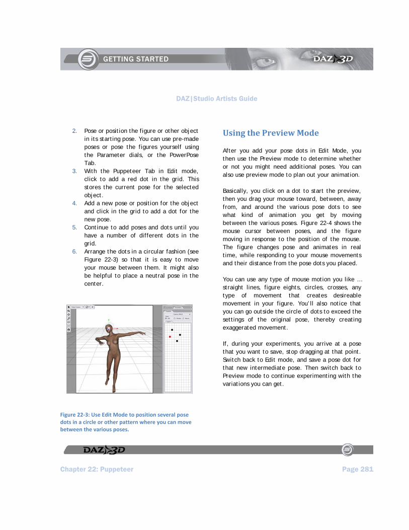
DAZ|Studio Artists Guide
Chapter 22: Puppeteer Page 281
2. Pose or position the figure or other object in its starting pose. You can use pre-made poses or pose the figures yourself using the Parameter dials, or the PowerPose Tab.
3. With the Puppeteer Tab in Edit mode, click to add a red dot in the grid. This stores the current pose for the selected object.
4. Add a new pose or position for the object and click in the grid to add a dot for the new pose.
5. Continue to add poses and dots until you have a number of different dots in the grid.
6. Arrange the dots in a circular fashion (see Figure 22-3) so that it is easy to move your mouse between them. It might also be helpful to place a neutral pose in the center.
Figure 22‐3: Use Edit Mode to position several pose dots in a circle or other pattern where you can move between the various poses.
Using the Preview Mode
After you add your pose dots in Edit Mode, you then use the Preview mode to determine whether or not you might need additional poses. You can also use preview mode to plan out your animation.
Basically, you click on a dot to start the preview, then you drag your mouse toward, between, away from, and around the various pose dots to see what kind of animation you get by moving between the various poses. Figure 22-4 shows the mouse cursor between poses, and the figure moving in response to the position of the mouse. The figure changes pose and animates in real time, while responding to your mouse movements and their distance from the pose dots you placed.
You can use any type of mouse motion you like … straight lines, figure eights, circles, crosses, any type of movement that creates desireable movement in your figure. You’ll also notice that you can go outside the circle of dots to exceed the settings of the original pose, thereby creating exaggerated movement.
If, during your experiments, you arrive at a pose that you want to save, stop dragging at that point. Switch back to Edit mode, and save a pose dot for that new intermediate pose. Then switch back to Preview mode to continue experimenting with the variations you can get.

DAZ|Studio Artists Guide
Page 282 Chapter 22: Puppeteer
Figure 22‐4: To preview your poses for potential animation sequences, click and drag your mouse cursor over, between, and around the pose dots. The figure changes pose in response to the mouse movement.
Using the Record Mode
After you preview your poses and movements, you’ll probably come upon a good range of mouse movements that will give you the type of animation you’re looking for. Now it’s time to switch to Record mode (.
Figure 22‐5: Record your mouse movements to the timeline in Record mode.
When you record your Puppeteer mouse movements, each mouse movement that you make (around, away from, and between the dots) is recorded in real time, including any pauses that you might make to keep your figure still. The recording continues for as long as you keep the mouse button pressed. Once you release the mouse button, the recording stops. You can click again at any time to start the recording session up again.
If the Timeline is not visible, choose View > Tabs > Timeline to display it. Then press the Play button and watch your animation play back exactly as you recorded it.
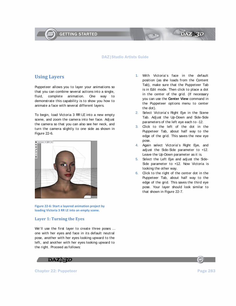
DAZ|Studio Artists Guide
Chapter 22: Puppeteer Page 283
Using Layers
Puppeteer allows you to layer your animations so that you can combine several actions into a single, fluid, complete animation. One way to demonstrate this capability is to show you how to animate a face with several different layers.
To begin, load Victoria 3 RR LE into a new empty scene, and zoom the camera into her face. Adjust the camera so that you can also see her neck, and turn the camera slightly to one side as shown in Figure 22-6.
Figure 22‐6: Start a layered animation project by loading Victoria 3 RR LE into an empty scene.
Layer 1: Turning the Eyes
We’ll use the first layer to create three poses … one with her eyes and face in its default neutral pose, another with her eyes looking upward to the left, and another with her eyes looking upward to the right. Proceed as follows:
1. With Victoria’s face in the default position (as she loads from the Content Tab), make sure that the Puppeteer Tab is in Edit mode. Then click to place a dot in the center of the grid. (If necessary you can use the Center View command in the Puppeteer options menu to center the dot).
2. Select Victoria’s Right Eye in the Scene Tab. Adjust the Up-Down and Side-Side parameters of the left eye each to -12.
3. Click to the left of the dot in the Puppeteer Tab, about half way to the edge of the grid. This saves the new eye pose.
4. Again select Victoria’s Right Eye, and adjust the Side-Side parameter to +12. Leave the Up-Down parameter as it is.
5. Select the Left Eye and adjust the Side-Side parameter to +12. Now Victoria is looking the other way.
6. Click to the right of the center dot in the Puppeteer Tab, about half way to the edge of the grid. This saves the third eye pose. Your layer should look similar to that shown in Figure 22-7.

DAZ|Studio Artists Guide
Page 284 Chapter 22: Puppeteer
Figure 22‐7: Create three eye poses and dots, one looking left, another neutral, and another looking right.
Now it’s time to use the Preview mode to get a feel for how the new morphs work. Move the mouse around the dots and watch how the eyes respond. Once you get an idea of how you want to create the animation, go into Record mode, and create an animation that is at least ten seconds (300 frames) long, but feel free to make it longer if you like. The animation will record for as long as you keep the mouse button pressed, and stops when you release the button.
Layer 2: Moving the Brows
Let’s add a little more expression to the face by adding another layer that raises her eyebrows. We’ll again create three poses … one with her eyebrows at the neutral position, another with the
brows raised, and another with the brows frowning. Follow these steps:
1. Return the Puppeteer tab to Edit mode. 2. From the Puppeteer options menu,
choose Add Layer. Name the new layer Brows and click OK.
3. With the face in its neutral position (which it should be because there are no other dots in the layer), click to place a dot in the center of the grid.
4. With the Head selected in the Scene Tab, scroll through the morphs in the Parameters Tab until you find BrowUpR and BrowUpL. Set both dials to 30%. Then click above the center dot to create a new dot in the Brows layer.
5. Now return to the Parameters Tab and set both brow dials back to zero. Move down to the BrowFrownR and BrowFrownL parameter dials and set them both to 115%. Click to set a new pose dot beneath the center dot.
6. After you set the third dot, return the Frown settings to zero. When you’re done your Brows layer should look similar to

DAZ|Studio Artists Guide
Chapter 22: Puppeteer Page 285
Figure 22‐8: Three dots are added to raise (upper), frown (lower) and return brows to neutral position (center).
Once again, enter Preview mode, and get a feel for the mouse movements you need to make to achieve results you like.
The real magic begins when you enter Record mode. But first you’ll have to make sure that you are starting the brow animation in the first frame. Use the Scrubber on the timeline, or the Current Frame field to move to the first frame (frame 0) in the animation. Then click inside the Puppeteer grid to begin your brow animation. You’ll notice that the timeline plays the first eye animation that you made, while also keeping track of the brow movements. Play a bit here … if you don’t like the results, you can always choose the Clear Layer Animation command from the Puppeteer Options Menu to remove the current layer animation and start the recording over again.
After you record your second layer animation, play it back and observe the results. Animation can’t get much more simple than that!
One More Layer: Head Movement
Now that you have two layers done you are no doubt beginning to see the power of layered animation and you have all sorts of ideas running through your head. We’ll go gentle on you in this tutorial, though, and will create one more animation layer. After that you can continue to experiment on your own to add more facial layers until you get a completely unique animation of your own. You can even use Mimic to add speech to the animation should you decide to make your character speak.

DAZ|Studio Artists Guide
Page 286 Chapter 22: Puppeteer
To create the head animation layer, follow these steps:
1. Return to the Puppeteer Tab and set it back to Edit mode.
2. Choose the Add Layer command from the Options menu, and name the new layer Head Movement.
3. Select the head from the Scene Tab and scroll through the list of dials in the Parameters Tab. Verify that all dials are set to zero. If they are not, use the Zero > Figure Morphs command in the Parameters Tab options menu to remove all morph settings from the figure.
4. With the head at its default position, click to add a dot in the center of the Puppeteer Grid.
5. At this point, create two or more additional head poses (the number is up to you), using combinations of the Bend, Twist, and Side-Side parameter dials. Create poses that make the head look up, down, left, right, or any combination thereof. Place the dots around the center dot so that you logically know the approximate way that the head is pointing. In other words, if the head is pointing up toward the left, place the dot above and to the left of the center dot. When you are finished making your poses (Figure 22-9), get ready to preview your animation layer.
Figure 22‐9: In a third layer, add several poses that move the head into various positions.
Once again, put Puppeteer into Preview mode to get a feel for the options you have. Another thing that hasn’t yet been mentioned is that if you find an intermediate pose that works well, you can stop your mouse movements at any time in preview mode, and return to Edit mode to save the current point as another pose dot.
After you are done with your preview, once again go into Record mode and watch the fun begin. As you build layer upon layer of animation, your head animation becomes more and more realistic.
Hopefully by now you see the power behind Puppeteer, and how it can assist you in creating realistic fluid motion that would take much longer
DAZ|Studio Artists Guide
Chapter 22: Puppeteer Page 287
than if you had to use traditional keyframe methods. Experiment and have fun with this innovative tool!

DAZ|Studio Artists Guide
DAZ|Studio Artists Guide Page 289
Section 7:
Appendices
DAZ|Studio Artists Guide
Appendix A: The Components of 3D Objects Page 290
Chapter 23 : The Components of 3D Objects
We all know that objects in the “real world” are three-dimensional. They have width, height, and depth. It’s impossible for a physical object to have any less than three dimensions; we wouldn’t be able to see them otherwise.
However, in the 3D world, you can have objects that have fewer than three dimensions. These theoretical dimensions are of immense value when you work within DAZ|Studio or other 3D software. In the 3D world, we can define objects by the number of dimensions they have:
Zero Dimensional (0D): A 0D object defines a location in space, called a point, or sometimes called a vertex when relating to a 3D model. A Point Light is a great example of a 0D object within DAZ|Studio since light emanates from a single point.
One Dimensional (1D): A 1D object is a single straight line that has length but no height or width. Straight lines are also called edges when they relate to a 3D model.
Two Dimensional (2D): A 2D object is a plane that has any two of the three dimensions (height and width, height and length, or width and length). You can also see them referred to as polygons or facets when they relate to a 3D object.
Three Dimensional (3D): A 3D object has all three dimensions (height, width, and
length). 3D objects are usually composed of many 2-dimensional polygons that form the shape of the 3D object.
Types of 3D Objects
So far, we’ve talked about the three dimensions (X, Y and Z). We’ve explored 0, 1, 2, and 3 dimensional objects, looked at Cartesian coordinates, and made comparisons between global axes and origins vs. local axes and origins. We’ve also learned about the types of motions you can apply to objects within DAZ|Studio. What exactly are these objects we keep talking about?
Points (Vertices)
As we touched on previously, a point has no dimension of its own. It does exist at a 3 dimensional position in space and has both a local and a global coordinate. For example, if a six-foot figure is standing ten feet in front of the origin, the point at the top of the figure’s head is at (0,6,0) in local coordinates and at (0,6,10) in global coordinates. If a figure at the global origin rotates 45 degrees to the left, the same point remains at (0,6,0) in local coordinates while moving to (-4.242,4,242,0) in global coordinates.
If a point defines a corner of a polygon, then it is called a vertex (singular) or vertices (plural).
Segments (Edges)
A segment is a 1D component with length, but no width or height. A segment connects two points to each other. Several 3D applications, including
Appendix A: The Components of 3D Objects Page 291
DAZ|Studio, often use segments to define the edges of polygons.
Lines (Splines)
A spline is similar to a segment in that it is a 1D component with length but no width or height own. It is also similar to a segment, in that it too, connects points to each other. One major difference, however, is that a spline can also be influenced by additional points, called control points. Splines are often used to create smooth curved lines using a minimal number of points, curves that would otherwise require many times the number of points, to be made with [linear] segments. Motion paths are perfect examples of splines. There are many types of splines, all of which are variations on the examples shown here. From left to right, they are:
Linear: Linear splines connect each end point without the influence of additional control points, a straight line.
Interpolating: Interpolating splines always pass through every control point. Linear splines are a form of interpolating spline. There are many ways to calculate interpolation.
Approximating: Approximating splines do not necessarily touch all of their control points. For these types of splines, the control points define the approximate shape, hence the term approximating. Again, there are many ways to calculate the approximations.
Polygons (Faces/Facets)
A polygon is a component whose corners are defined by vertices and connected by edges. Creating a polygon involves placing one point for each corner, then connecting the vertices to form a closed loop, or face. Polygons can have 3 sides (triangle), 4 sides (quadrangle), or more than 4 sides (commonly referred to as n-sided). Polygons
defined by three points are always considered planar (2D), as three points are needed to define an arbitrary plane. Polygons with four or more points may be planar as well, but are subject to becoming convex (bowing out) or concave (bowing in) depending on the coordinates of the vertices that define the face. Convex or concave polygons are often the culprits behind artifacts (anomalies) in a render of a polygonal mesh.
Objects (Meshes)
While vertices and edges define polygons, all 3D objects in DAZ|Studio consist of many polygons arranged into a mesh that has the form of the desired object, such as a human, chair, dragon, plant, building, etc. The left side of the image shows Vicky as a polygon mesh. If you’ve ever seen a piece of jewelry, you know that gemstones have facets or a series of flat sides cut in such a way as to create a shape. If DAZ|Studio only displayed polygons, then all 3D objects would have this faceted appearance, resulting in a significant loss of realism. DAZ|Studio therefore employs polygon smoothing, which makes the collection of planar polygons appear like smooth rounded objects. Throw in a material and you have a realistic 3D object as shown on the right side of the image.
An object that consists of two or more polygons is interchangeably called a polygon mesh, a mesh object, or simply a mesh. DAZ|Studio uses meshes for figures (human, animal, and otherwise) and props (such as furniture, hair, etc.). Other items, such as lights, may appear as polygon meshes but that is strictly for viewport display purposes, and do not render.
Material Groups
In order for DAZ|Studio to assign materials properly, the polygons that make up a mesh must be assigned to one or more groups. Every mesh object is different and will have different groups unique to that object. There are many types of
Page 292 Appendix A: The Components of 3D Objects
groups; this section covers surfaces, which comprise the group type used in DAZ|Studio.
Surfaces
A figure or prop in your scene can have several different surfaces. For example, a human figure may have skin, finger and toenails, irises, etc. Surfaces allow you to change the look of part of an
object without affecting the whole thing. For example, you could make a figure’s fingernails red without changing the skin color. If you’re working with a figure that includes built-in clothing, the upper arm may have skin and shirt surfaces assigned to it. A polygon that belongs to one surface cannot belong to another surface. The image here shows an example of surface groups, where the figure’s surfaces each bear different colors.

DAZ|Studio Artists Guide
Appendix B: Bones and Hierarchies Page 294
Chapter 24 : Bones and Hierarchies
A typical figure creation process works like this:
Build the polygon mesh. Build the bones inside the mesh and
create a hierarchy. Adjust the bone locations. Define which bone controls which vertices
(create vertex weight maps). Define the degrees and range of motion
for each bone.
Like you, DAZ|Studio figures have bones that can move and bend. Your bones control how your body bends. Your knees bend along one axis while your back can bend around all three, and so forth. In addition to defining the type or degrees of freedom, your bones define the range of motion. Your arm can only extend until it is straight out. Your wrists cannot bend backward more than 90 degrees or so.
At the same time, the bones in your body are arranged in a specific order. In the 3D world, the way that bones are arranged is called a hierarchy, which tells DAZ|Studio how bones are connected to each other, much like the old song “Dry Bones” that works its way up from the toes to the neck. You know … the toe bone is connected to the foot, which is connected to the ankle, which is connected to the leg, which is connected to the knee, and so on.
Bones
When you load a figure, DAZ|Studio reads the mesh and the bone information. This information allows the application to deform the mesh in accordance with the vertex weight maps or falloff zones, bones, and rotation information.
There is one more wrinkle … literally … to bones and deforming meshes. When you bend your elbow, the skin and muscle on the inside of your elbow contracts while the skin on the outside of your elbow stretches out. This change is most pronounced right at your joint and decreases with distance. Skin more than a couple inches away from your joint remains unchanged. On your body, this occurs because of your skin and muscular elasticity.
DAZ|Studio has no intrinsic way of knowing how to handle the deformation. However, there are two ways to provide this information:
Falloff zones: A falloff zone defines the area that is affected by the bending motion. In general, the area towards the center of the zone deforms the most, and then decreases (or falls off) over distance until it reaches 0 at the edge of the zone. Falloff zones are relatively simple for the content creator to implement in their content. The drawback is lack of fine control. DAZ|Studio can read falloff zone information in imported content.
Vertex weight map: Objects are made of polygons, and each polygon has a vertex, or point, at each of its “corners.” A
Appendix B: Bones and Hierarchies Page 295
vertex weight map performs the same function as a falloff zone, but offers far more precise control. Vertex weight maps can assign varying degrees of deformation to any or all of the vertices in the model.
The Hierarchical Chain
We now have created a bone structure that defines where and how the object bends. Now we need to define a hierarchy that determines what other bones, if any, are affected when you move any given bone. In addition, you can also use hierarchies to define interactions between objects.
Hierarchies
Hold your arm straight and rotate your shoulder in any direction. Notice what happened: As your shoulder moved, so did your upper arm, forearm, hand, and fingers, while the rest of your body remained in its original position. Now move your fingers and notice that the rest of your arm remains still. Now bend your elbow. Your shoulder and upper arm remain still while your forearm, hand, and fingers move. This is a perfect example of a hierarchy, or situation where different components exert a greater or lesser degree of influence over others.
Hierarchies are often referred to as parent/child relationships within many 3D applications (including DAZ|Studio). Children are affected by their parents, but not the other way around. Using the previous example, your shoulder is the parent of your entire arm, with your upper arm, forearm, hand, and fingers being children. Your elbow is both a parent of your forearm, hand, and fingers and a child of your shoulder. Thus, bending the shoulder moves your entire arm while bending your elbow only moves your elbow’s children.
Remember our discussion about global versus local coordinates? The same concept applies here as
well. By moving your shoulder, each part of your arm has changed its absolute position while its relative position remains unchanged. For example, if you raise your arm, your elbow will move higher but will still remain the exact distance from your shoulder. This action is called forward kinematics.
Parent/Child Relationships Between Objects
So far, we’ve only discussed parent/child relationships within the same object, such as a figure or prop. You can also create parent/child relationships between objects in your scene. Here are just a few examples:
Hair props are children of a figure’s head, meaning that the hair will move with the head.
You can place a hat on a figure’s head. If you forget to make it a child of the head, the hat will remain still while your figure moves. Establishing a parent/child relationship allows the hat to remain on the figure’s head and in the same position relative to the head. For example, if you parent a baseball cap to a figure’s head, the brim will always be over the figure’s face just like its real-world counterpart.
You can place an object in a figure’s hand (such as a pen, ball, tool, etc.) and the object will remain in its position. To create a construction worker swinging a hammer, parent the hammer to the figure’s hand. As you rotate the figure’s arm or move the figure’s body, the hammer will remain in the figure’s hand.
You can have a camera follow any body part, prop, or any other item in your scene. There are different ways to do this.
There are many other possible examples; you will discover this as you become more familiar with DAZ|Studio.
DAZ|Studio Artists Guide
Appendix C: Other DAZ Products Page 296
Chapter 25 : Other DAZ Products
As you begin using DAZ|Studio for custom projects, you’ll need to obtain characters, props, and other content beyond the starter content supplied with the program.
DAZ figures are a wonderful addition to any existing 3D library. The Millennium Figures are completely set up and ready to work in DAZ|Studio. They give artists realism and versatility that is unmatched by
any other commercially available 3D models. DAZ releases updates and other additions for each figure on a regular basis, giving you an ever-expanding array of options.
As you continue delving into DAZ|Studio and creating more scenes, you will need to add content to your library. DAZ is the leading creator and publisher of high-quality 3D content including figures, props, textures, and more. We also create other software applications. Visit us on the Web at http://www.daz3d.com to see our growing collection of content!

DAZ|Studio Artists Guide
Appendix D: End User License Agreement Page 297
Chapter 26 : EULA
By using the software you signify that you have read and agree to all the terms of the license agreement.
AGREEMENT. THIS IS A LEGAL AND BINDING AGREEMENT BETWEEN YOU, HEREINAFTER ALSO REFERRED TO AS "USER", AND DAZ Productions, INC., HEREINAFTER ALSO REFERRED TO AS "DAZ 3D". BY INSTALLING THIS PROGRAM OR USING THESE 3-D APPLICATION(S), MOTIONS, TEXTURE MAP(S), BUMP MAP(S) OR ANY OTHER 3D RELATED PRODUCTS, HERINAFTER REFERRED AS 3-D APPLICATION(S), (OR AUTHORIZING ANY OTHER PERSON TO DO SO), YOU INDICATE YOUR COMPLETE AND UNCONDITIONAL ACCEPTANCE OF ALL THE TERMS AND CONDITIONS OF THIS LICENSE AGREEMENT. THIS LICENSE AGREEMENT CONSTITUTES THE COMPLETE AGREEMENT BETWEEN YOU AND DAZ 3D. IF YOU DO NOT AGREE TO THE TERMS OF THIS LICENSE AGREEMENT, YOU MAY DESTROY THE INSTALLED PROGRAM PACKAGE (WITH ALL ACCOMPANYING MATERIALS). YOU MUST DELETE THEM FROM YOUR COMPUTER AND FROM ANY BACKUP DEVICES THAT YOU MAY HAVE USED.
1. 3-D PROGRAM LICENSE. DAZ 3D grants to User and User hereby accepts, subject to the limitations and obligations of this Agreement, a personal non-exclusive, nontransferable License to use the 3-D Application(s), together with all accompanying written materials (collectively referred to as "3-D Application(s)").
2. TITLE AND OWNERSHIP. Notice is hereby given that the 3-D Application(s) contains copyrighted and/or proprietary information protected by the laws of the United States. DAZ 3D retains all rights in, title to, and ownership of the 3-D Application(s). User shall take all steps reasonably necessary to protect DAZ 3D'S ownership rights.
3. LICENSE FEES. DAZ 3D agrees to provide the 3-D Application at no charge. 4. COPYING RESTRICTIONS. The 3-D Application(s) may be copied in whole or in part for User's exclusive
use. Unauthorized copying of the 3-D Application(s) is expressly forbidden. User expressly agrees to include DAZ 3D'S (and third parties, if any) copyright notice(s) and proprietary interest(s) on all copies of the 3-D Application(s), in whole or in part, in any form, including data form, made by User in accordance with this Agreement.
The 3-D Application(s) is provided for User's exclusive use. User does not have the right to provide the 3-D Application(s) to others in any form or on any media.
5. TELLWARE. This application is considered tellware. The user is required to tell two other people where to download this application (www.daz3d.com) in order to install and or use it. Note: During
Page 298 Appendix D: End User License Agreement
the alpha phase of testing, users will not be required to follow this program due to the test base being a closed group. During the alpha stage of testing, DAZ|Studio will only be distributed to Platinum Club members.
6. OTHER RESTRICTIONS. This Agreement is your proof of License to exercise the rights granted herein and must be retained by you. User shall not give, sell, rent, lease, sublicense, or otherwise transfer or dispose of the 3-D Application(s) on a temporary or permanent basis without the prior written consent of DAZ 3D. DAZ 3D'S 3-D Application(s) and/or contracts are non-transferable and shall only be used by the Licensed User. User may not reverse engineer, decompile, disassemble, or create derivative works from the 3-D Application(s). These restrictions do not pertain to rendered images or pre-rendered animations.
7. PROTECTION AND SECURITY. User agrees not to disclose, publish, release, transfer, or otherwise make available the 3-D Application(s), or any portion thereof, in any form, to any person, without prior written consent from DAZ 3D. User agrees that the 3-D Application(s) is the property of and proprietary to DAZ 3D, and further agrees to protect the 3-D Application(s) and all parts thereof from unauthorized disclosure and use by its agents, employees, or customers. User shall be exclusively responsible for the selection, supervision, management, control, and use of the 3-D Application(s). User agrees to utilize its best efforts to see that its employees or any other user of the 3-D Application(s) complies with the terms and conditions of this Agreement and refrains from taking any steps, such as reverse assembly or reverse compilation, to derive a source code equivalent of the 3-D Applications.
8. EXPORT RESTRICTIONS. The 3-D Application(s) may be subject to the export controls of the United States Departments of State and Commerce and User agrees to fully comply with all applicable United States export regulations governing export, destination, ultimate end user, and other restrictions relating to the 3-D Applications.
9. UNITED STATES GOVERNMENT RESTRICTED RIGHTS. If you are acquiring the 3D Application(s) on behalf of any unit or agency of the United States Government, the following provision applies--It is acknowledged that the 3-D Application(s) and the documentation were developed at private expense and that no part is in the public domain and that the 3-D Application(s) and documentation are provided with restricted rights. Use, duplication, or disclosure by the Government is subject to restrictions as set forth in Subparagraph (c)(1)(ii) of the Rights in Technical Data and Computer Software clause at DFARS 252.227-7013, or Subparagraphs (c)(1) and (2) of the Commercial Computer Software--Restricted Rights at 48 CFR 52.227-19, as applicable. Contractor/Manufacturer is DAZ Productions, INC., 12401 S. 450 E. #F-1, Draper, UT 84020.
10. PATENT, COPYRIGHT, AND TRADE SECRET INDEMNITY. User agrees to indemnify and hold harmless DAZ 3D against all liability resulting from or related to any claim of patent or copyright infringement, misappropriation, or misuse of trade secrets or other proprietary rights based upon the use by User of the 3-D Application(s), or any portion thereof, in whatever form, or the exercise by User of any rights granted under this Agreement.
11. LIMITED WARRANTY. DAZ 3D warrants that the 3-D Application(s) will perform substantially in accordance with the accompanying written materials for a period of seven (7) days from the date of receipt.
12. NO OTHER WARRANTIES. DAZ 3D DISCLAIMS ALL OTHER WARRANTIES, EXPRESS OR IMPLIED, INCLUDING, BUT NOT LIMITED TO, ANY IMPLIED WARRANTIES OF MERCHANTABILITY OR FITNESS FOR A PARTICULAR PURPOSE, OR ARISING FROM USAGE OF TRADE OR COURSE OF DEALING OR PERFORMANCE, WITH RESPECT TO THE 3-D Application(S), AND THE ACCOMPANYING WRITTEN MATERIALS. IN NO EVENT SHALL DAZ 3D OR ITS DEALERS, DISTRIBUTORS, OFFICERS, AGENTS,

Appendix D: End User License Agreement Page 299
EMPLOYEES, OR SUPPLIERS BE LIABLE FOR ANY DAMAGES WHATSOEVER, WHETHER BASED ON CONTRACT, TORT, WARRANTY, OR OTHER LEGAL OR EQUITABLE GROUNDS, INCLUDING, WITHOUT LIMITATION, DAMAGES FOR LOSS OF BUSINESS PROFITS, BUSINESS INTERRUPTION, LOSS OF BUSINESS INFORMATION, OR OTHER PECUNIARY LOSS, ARISING OUT OF THE USE OF OR INABILITY TO USE THE 3-D Application(S), EVEN IF DAZ 3D HAS BEEN ADVISED OF THE POSSIBILITY OF SUCH DAMAGES. BECAUSE SOME STATES DO NOT ALLOW THE EXCLUSION OR LIMITATION OF LIABILITY FOR CONSEQUENTIAL OR INCIDENTAL DAMAGES, THE ABOVE LIMITATION MAY NOT APPLY TO YOU.
13. NO LIABILITY FOR HARDWARE. User assumes complete responsibility for all hardware used in conjunction with the 3-D Application(s). DAZ 3D shall not be responsible in any way for the non-performance or malfunction of any hardware used in conjunction with the 3-D Application(s), nor for any damages whatsoever arising out of the use of any hardware.
14. INDEMNIFICATION. User shall defend, indemnify, and hold DAZ 3D harmless from any actions, claims, or proceedings with respect to the 3-D Application(s) or other provisions of this Agreement.
15. REMEDIES. The remedies provided herein shall not be deemed exclusive, but shall be cumulative and shall be in addition to all other remedies provided by law and equity. No delay or omission in the exercise of any remedy herein provided or otherwise available to DAZ 3D shall impair or effect DAZ 3D'S right to exercise the same. An extension of indulgence or forbearance (which must be in writing) shall not otherwise alter or effect DAZ 3D'S rights or obligations nor be deemed to be a waiver thereof. The parties hereto agree that breach of any provisions of non-disclosure, secrecy, confidentiality, copying, use, protection, and security in this Agreement by User will cause immediate and irreparable damage and injury to DAZ 3D. Each of the parties confirms that damages at law may be an inadequate remedy for breach or threatened breach of any such provisions. The parties agree that in such event DAZ 3D shall be entitled by right to an Injunction restraining the User from violating any of said provisions. User hereby acknowledges that DAZ 3D has disclosed or will disclose to User valuable proprietary data set products, which are new and unique and give DAZ 3D a competitive advantage in the marketplace; that DAZ 3D intends to use such information to expand its business throughout the world; and that a violation of any of the provisions of this Agreement is material and important and DAZ 3D shall, in addition to all other rights and remedies available hereunder, at law or otherwise, be entitled to a Temporary Restraining Order and an Injunction to be issued by any court of competent jurisdiction enjoining and restraining User from committing any violation of said provisions, and User shall consent to the issuance of such Injunction. User acknowledges that the remedies provided for in this Agreement are not injurious to nor violative of any public interest or policy, and will not create a hardship greater than is necessary to protect the interest of DAZ 3D.
16. GENERAL PROVISIONS.
a. Costs and Expenses of Enforcement. In the event of the failure of either party hereto to comply with any provisions of this Agreement, the defaulting party shall pay any and all costs and expenses, including reasonable attorneys' fees arising out of or resulting from such default (including any incurred in connection with any appeal), incurred by the injured party in enforcing its rights and remedies, whether such right or remedy is pursued by filing a lawsuit or otherwise.
b. Governing Law, Jurisdiction, and Venue. This Agreement is governed by the laws of the State of Utah. Jurisdiction and venue for the enforcement of this Agreement shall be found exclusively in the courts within Utah County, State of Utah.
Page 300 Appendix D: End User License Agreement
c. Further Information. Should you have any questions concerning any of the provisions of this Agreement, or if you desire to contact DAZ 3D, please write: DAZ Productions, INC., 1350 E. Draper Parkway, Draper, UT 84020. If you need technical support for a DAZ 3D product, please call (801) 495-1777. Our technical support hours are 9:00 a.m. to 5:00 p.m. M.S.T.
d. Trademark and Copyright. All DAZ 3D products are trademarks or registered trademarks of DAZ Productions, INC. All other brand and product names are trademark or registered trademark of their respective holders.
DAZ Productions, INC., 1995.
Contact Information: DAZ Productions 1350 East Draper Parkway Draper, UT 84020 Phone:(801) 495-1777 FAX:(801) 495-1787 TOLL-FREE 1-800-267-5170 www.daz3d.com