Embed Size (px)
Citation preview
DC MOTOR DRIVES(MEP 1422)
Dr. Nik Rumzi Nik Idris
Department of Energy Conversion
FKE, UTM
Contents• Introduction
– Trends in DC drives– DC motors
• Modeling of Converters and DC motor– Phase-controlled Rectifier– DC-DC converter (Switch-mode)– Modeling of DC motor
• Closed-loop speed control– Cascade Control Structure– Closed-loop speed control - an example
• Torque loop• Speed loop
• Summary
INTRODUCTION
• DC DRIVES: Electric drives that use DC motors as the prime movers
• Dominates variable speed applications before PE converters were introduced
• DC motor: industry workhorse for decades
• Will AC drive replaces DC drive ?
– Predicted 30 years ago
– AC will eventually replace DC – at a slow rate
– DC strong presence – easy control – huge numbers
Introduction
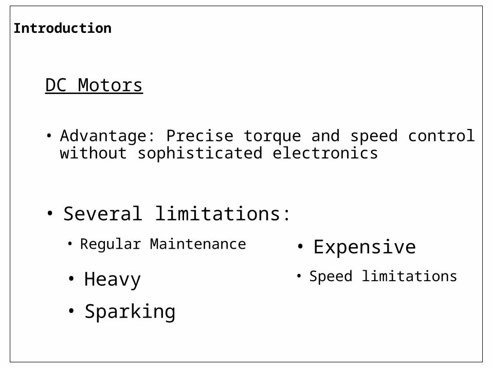
DC Motors
• Several limitations:
• Advantage: Precise torque and speed control without sophisticated electronics
• Regular Maintenance • Expensive
• Heavy • Speed limitations
• Sparking
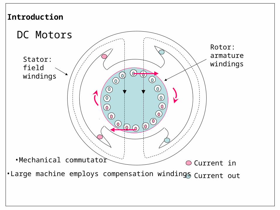
Current in
Current out
Stator: field windings
Rotor: armature windings
Introduction
DC Motors
•Mechanical commutator
•Large machine employs compensation windings
Introduction
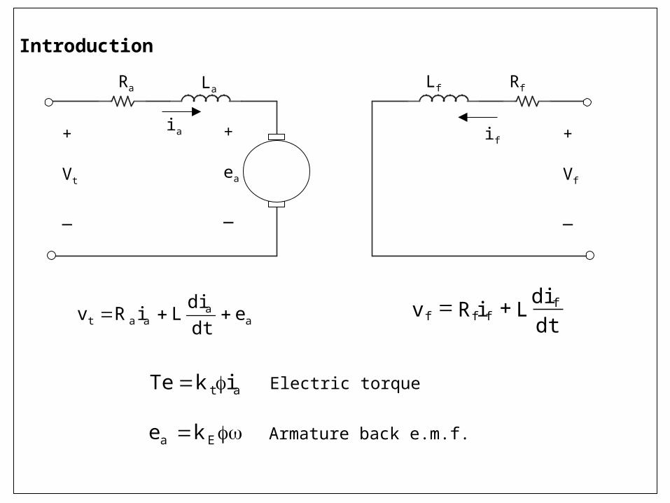
at ikTe Electric torque
Ea ke Armature back e.m.f.
Lf Rf
if
aa
aat edtdi
LiRv
+
ea
_
LaRa
ia+
Vt
_
+
Vf
_
dtdi
LiRv ffff
Introduction
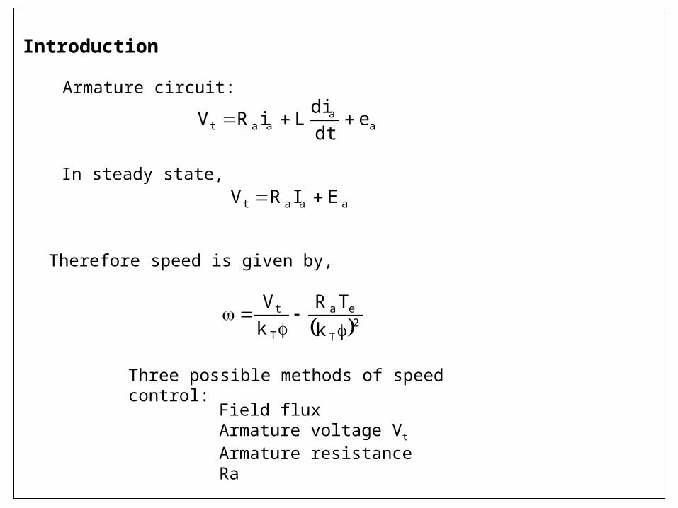
aaat EIRV In steady state,
2T
ea
T
t
k
TRkV
Therefore speed is given by,
Three possible methods of speed control:
Field fluxArmature voltage Vt
Armature resistance Ra
aa
aat edtdi
LiRV
Armature circuit:
Introduction
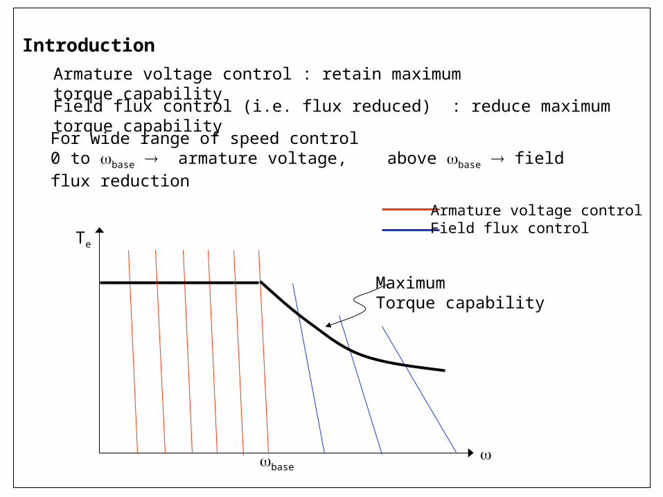
For wide range of speed control 0 to base armature voltage, above base field flux reduction
Armature voltage control : retain maximum torque capability
Field flux control (i.e. flux reduced) : reduce maximum torque capability
Te
MaximumTorque capability
Armature voltage controlField flux control
base
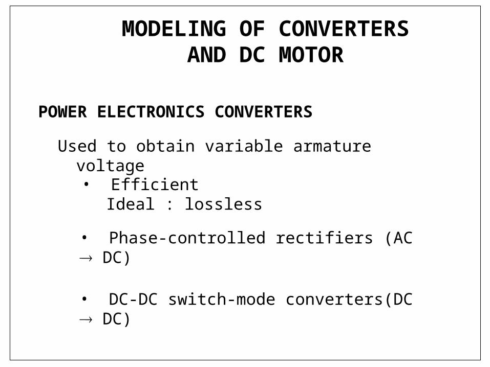
MODELING OF CONVERTERS AND DC MOTOR
Used to obtain variable armature voltage
POWER ELECTRONICS CONVERTERS
• Efficient Ideal : lossless
• Phase-controlled rectifiers (AC DC)
• DC-DC switch-mode converters(DC DC)

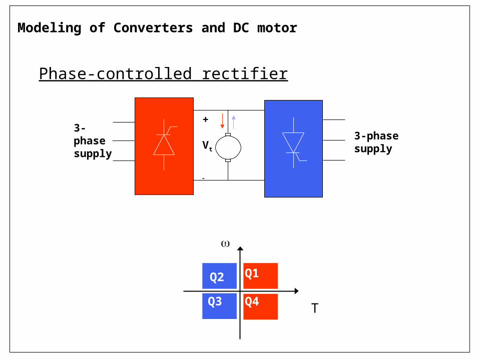
Modeling of Converters and DC motor
Phase-controlled rectifier (AC–DC)
T
Q1Q2
Q3 Q4
3-phasesupply
+
Vt
ia
Phase-controlled rectifier
Q1Q2
Q3 Q4
T
3-phasesupply
3-phasesupply
+
Vt
Modeling of Converters and DC motor
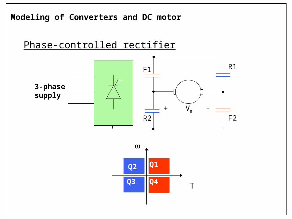
Phase-controlled rectifier
Q1Q2
Q3 Q4
T
F1
F2
R1
R2+ Va -
3-phasesupply
Modeling of Converters and DC motor
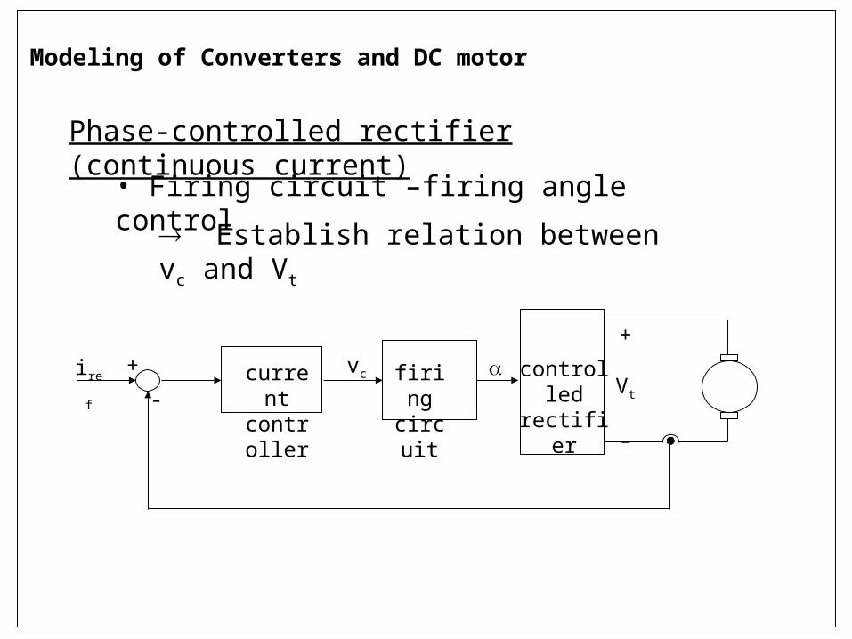
Phase-controlled rectifier (continuous current)
• Firing circuit –firing angle control
Establish relation between vc and Vt
firingcircuit
currentcontroller
controlled rectifier
+
Vt
–
vciref+
-
Modeling of Converters and DC motor
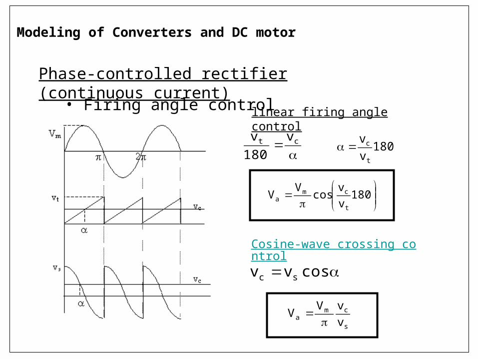
Phase-controlled rectifier (continuous current)
• Firing angle control
180vv
cosV
Vt
cma
ct v
180v
180vv
t
c
linear firing angle control
cosvv sc
Cosine-wave crossing control
s
cma v
vVV
Modeling of Converters and DC motor
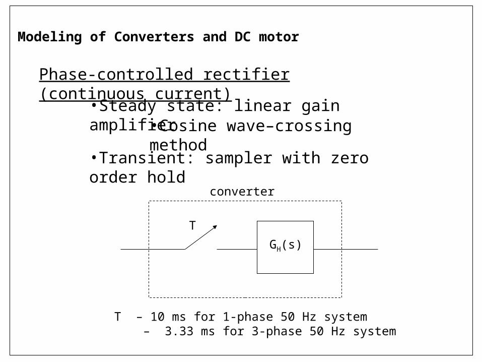
Phase-controlled rectifier (continuous current)
•Steady state: linear gain amplifier•Cosine wave–crossing method
Modeling of Converters and DC motor
•Transient: sampler with zero order hold
T
GH(s)
converter
T – 10 ms for 1-phase 50 Hz system – 3.33 ms for 3-phase 50 Hz system
0.3 0.31 0.32 0.33 0.34 0.35 0.36-400
-200
0
200
400
0.3 0.31 0.32 0.33 0.34 0.35 0.36-10
-5
0
5
10
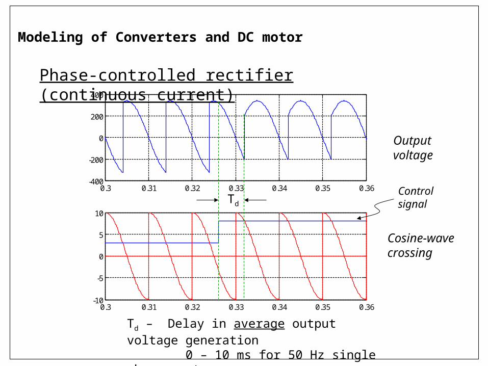
Phase-controlled rectifier (continuous current)
Td
Td – Delay in average output voltage generation 0 – 10 ms for 50 Hz single phase system
Outputvoltage
Cosine-wave crossing
Control signal
Modeling of Converters and DC motor
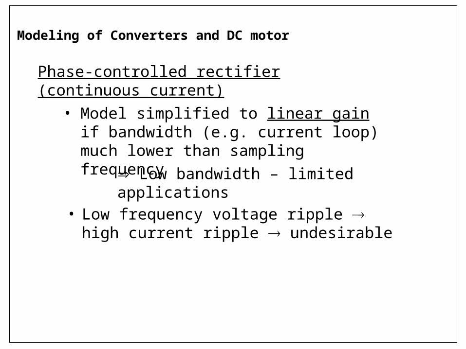
Phase-controlled rectifier (continuous current)
• Model simplified to linear gain if bandwidth (e.g. current loop) much lower than sampling frequency
Low bandwidth – limited applications
• Low frequency voltage ripple high current ripple undesirable
Modeling of Converters and DC motor
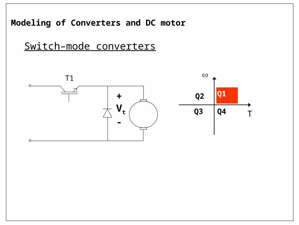
Switch–mode converters
Q1Q2
Q3 Q4
T
+Vt
-
T1
Modeling of Converters and DC motor
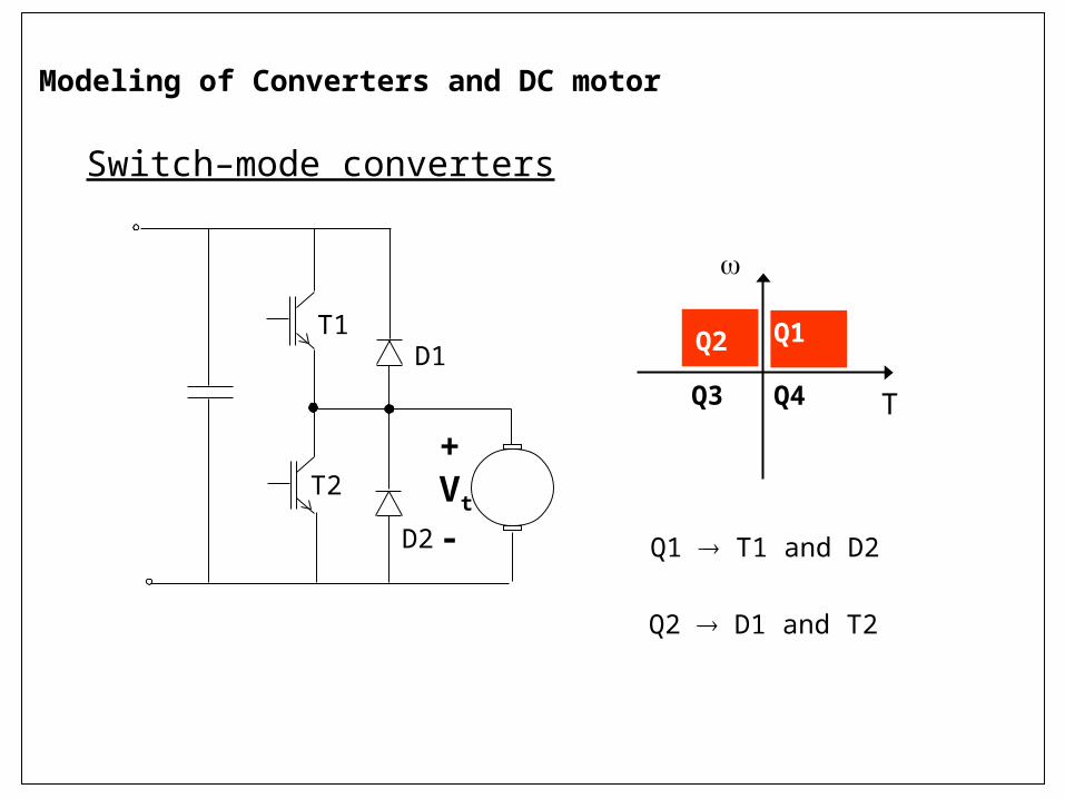
Switch–mode converters
+Vt
-
T1D1
T2
D2
Q1Q2
Q3 Q4
T
Q1 T1 and D2
Q2 D1 and T2
Modeling of Converters and DC motor
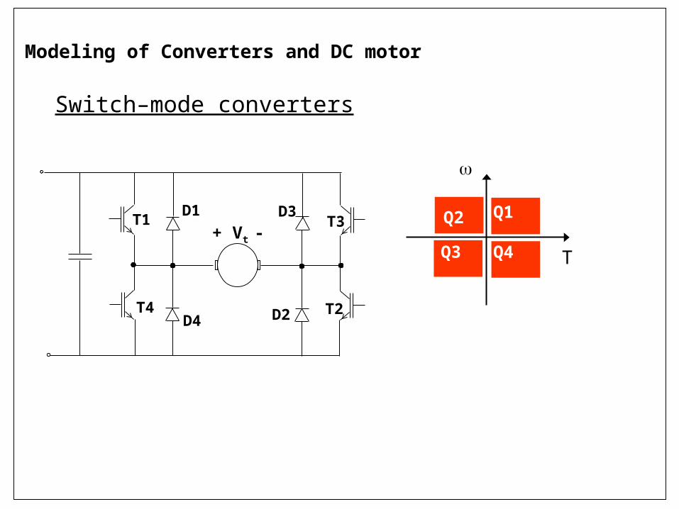
Switch–mode converters
Q1Q2
Q3 Q4
T+ Vt -
T1D1
T2D2
D3
D4
T3
T4
Modeling of Converters and DC motor
Switch–mode converters
• Switching at high frequency
Reduces current ripple
Increases control bandwidth
• Suitable for high performance applications
Modeling of Converters and DC motor
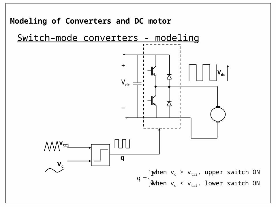
Switch–mode converters - modeling
+
Vdc
−
Vdc
vc
vtri
q
0
1q
when vc > vtri, upper switch ON
when vc < vtri, lower switch ON
Modeling of Converters and DC motor
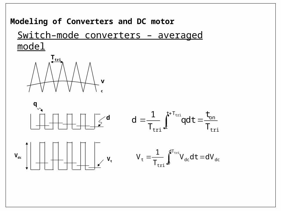
tri
onTt
ttri Tt
dtqT1
dtri
vc
q
Ttri
d
Switch–mode converters – averaged model
Modeling of Converters and DC motor
dc
dT
0dc
trit dVdtV
T1
Vtri
Vdc Vt
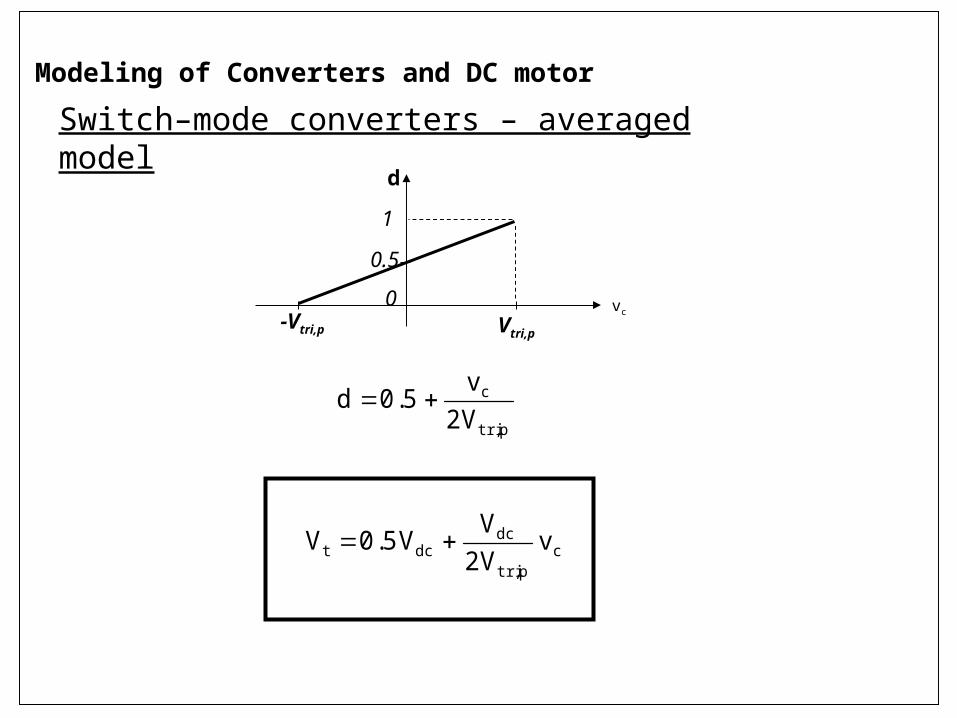
Vtri,p-Vtri,pvc
d
1
0
0.5
p,tri
c
V2v
5.0d
cp,tri
dcdct v
V2V
V5.0V
Switch–mode converters – averaged model
Modeling of Converters and DC motor
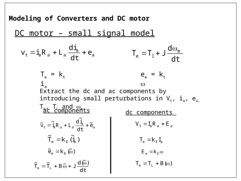
DC motor – small signal model
Modeling of Converters and DC motor
Extract the dc and ac components by introducing small perturbations in Vt, ia, ea, Te, TL and m
aa
aaat edtdi
LRiv
Te = kt ia ee = kt
dtd
JTT mle
aa
aaat e~dti~
dLRi
~v~
)i~(kT
~aEe
)~(ke~ Ee
dt)~(d
J~BT~
T~
Le
ac components
aaat ERIV
aEe IkT
Ee kE
)(BTT Le
dc components
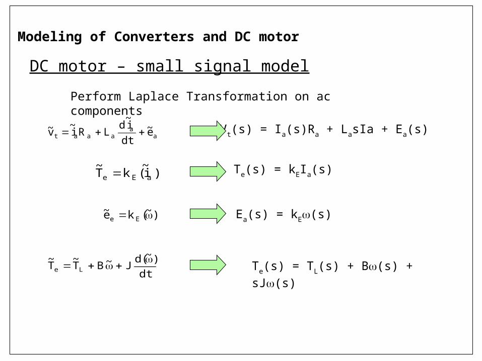
DC motor – small signal model
Modeling of Converters and DC motor
Perform Laplace Transformation on ac components
aa
aaat e~dti~
dLRi
~v~
)i~(kT
~aEe
)~(ke~ Ee
dt)~(d
J~BT~
T~
Le
Vt(s) = Ia(s)Ra + LasIa + Ea(s)
Te(s) = kEIa(s)
Ea(s) = kE(s)
Te(s) = TL(s) + B(s) + sJ(s)
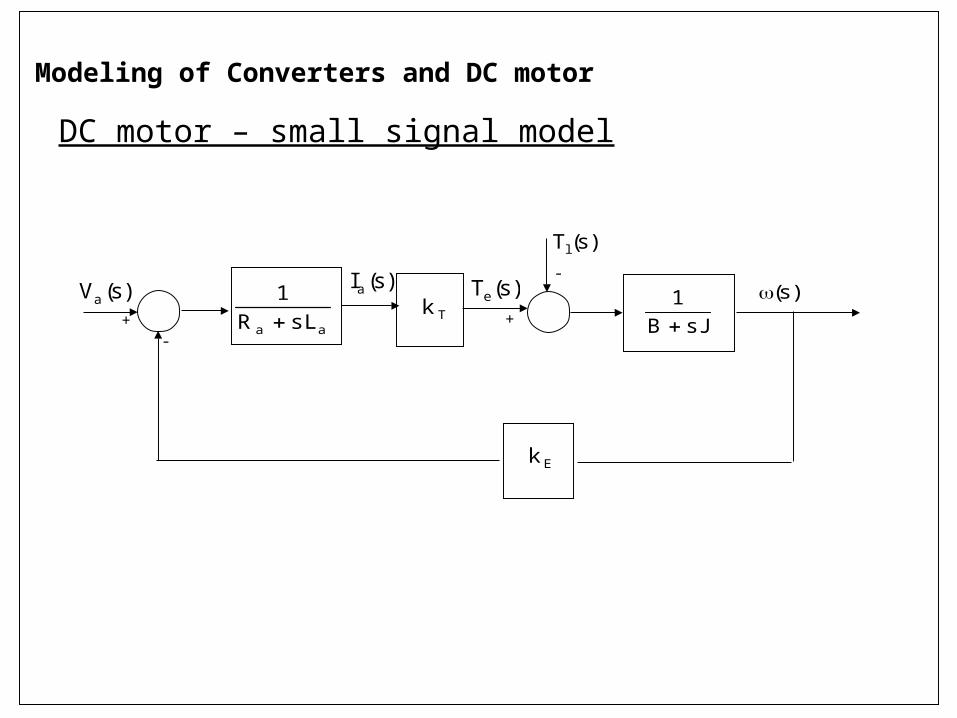
DC motor – small signal model
Modeling of Converters and DC motor
Tkaa sLR
1
)s(Tl
)s(Te
sJB1
Ek
)s(Ia )s()s(Va
+-
-
+
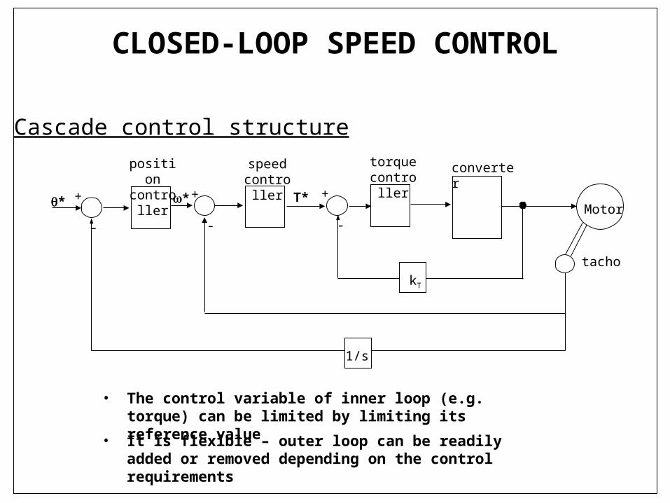
CLOSED-LOOP SPEED CONTROL
Cascade control structure
• It is flexible – outer loop can be readily added or removed depending on the control requirements
• The control variable of inner loop (e.g. torque) can be limited by limiting its reference value
1/s
convertertorquecontroller
speedcontroller
positioncontroller
+
-
+
-
+
-
tacho
Motor* T**
kT
CLOSED-LOOP SPEED CONTROL
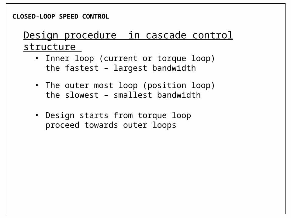
Design procedure in cascade control structure
• Inner loop (current or torque loop) the fastest – largest bandwidth
• The outer most loop (position loop) the slowest – smallest bandwidth
• Design starts from torque loop proceed towards outer loops
CLOSED-LOOP SPEED CONTROL
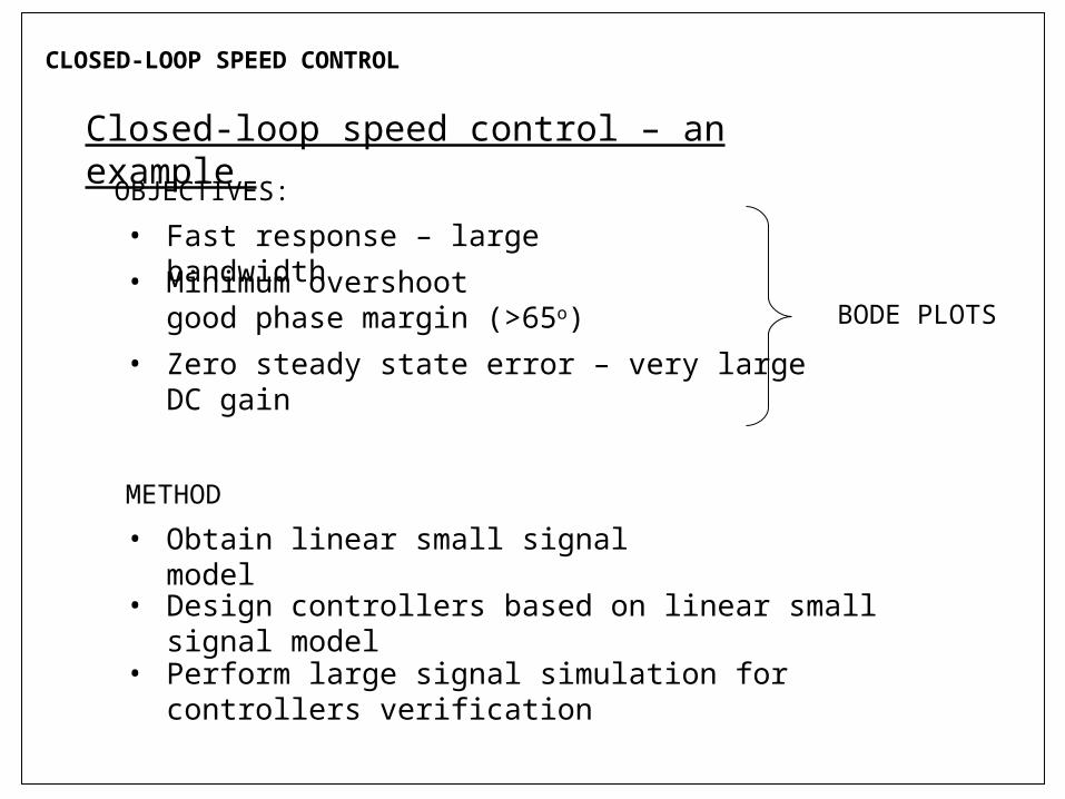
Closed-loop speed control – an example
OBJECTIVES:
• Fast response – large bandwidth
• Minimum overshoot good phase margin (>65o)
• Zero steady state error – very large DC gain
BODE PLOTS
• Obtain linear small signal model
METHOD
• Design controllers based on linear small signal model
• Perform large signal simulation for controllers verification
CLOSED-LOOP SPEED CONTROL
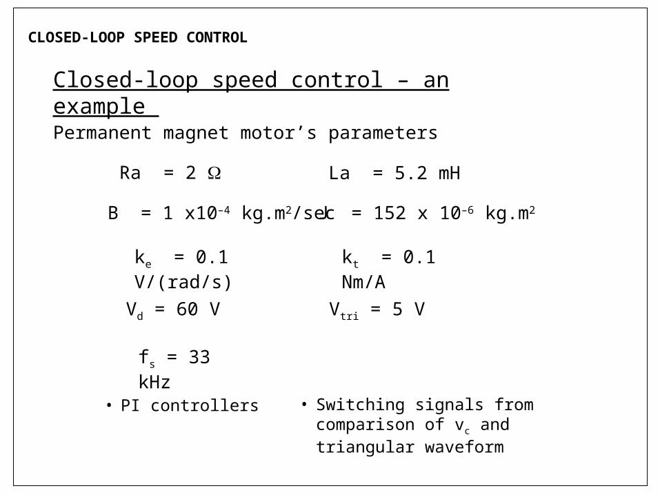
Ra = 2 La = 5.2 mH
J = 152 x 10–6 kg.m2B = 1 x10⁻⁴ kg.m2/sec
kt = 0.1 Nm/Ake = 0.1 V/(rad/s)
Vd = 60 V Vtri = 5 V
fs = 33 kHz
Permanent magnet motor’s parameters
Closed-loop speed control – an example
• PI controllers • Switching signals from comparison of vc and triangular waveform
CLOSED-LOOP SPEED CONTROL
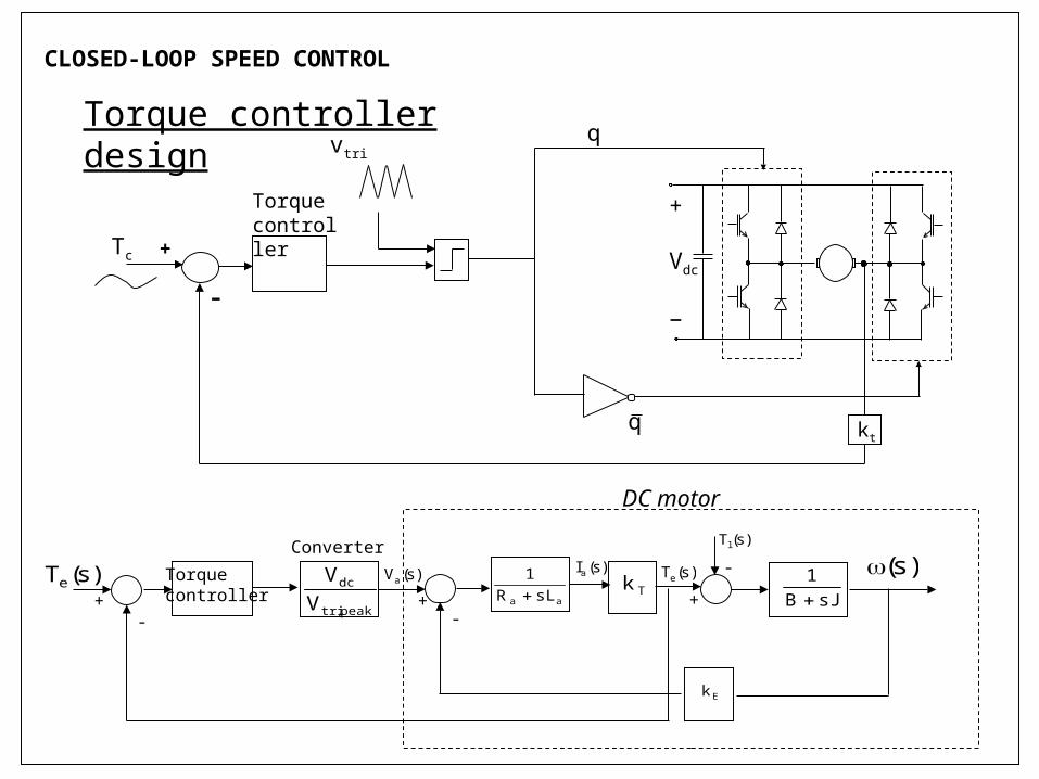
Torque controller design
Tc
vtri
+
Vdc
−
q
q
+
–
kt
Torque controller
Tkaa sLR
1
)s(Tl
)s(Te
sJB1
Ek
)s(Ia )s()s(Va
+-
-
+
Torquecontroller
Converter
peak,tri
dc
VV)s(Te
-+
DC motor
Bode Diagram
Frequency (rad/sec)
-50
0
50
100
150From: Input Point To: Output Point
Mag
nitu
de (
dB)
10-2
10-1
100
101
102
103
104
105
-90
-45
0
45
90
Pha
se (
deg)
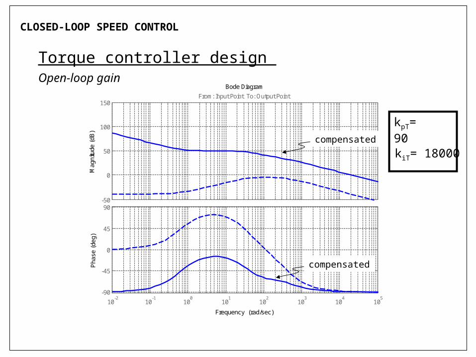
CLOSED-LOOP SPEED CONTROL
Torque controller design Open-loop gain
compensated
compensated
kpT= 90
kiT= 18000
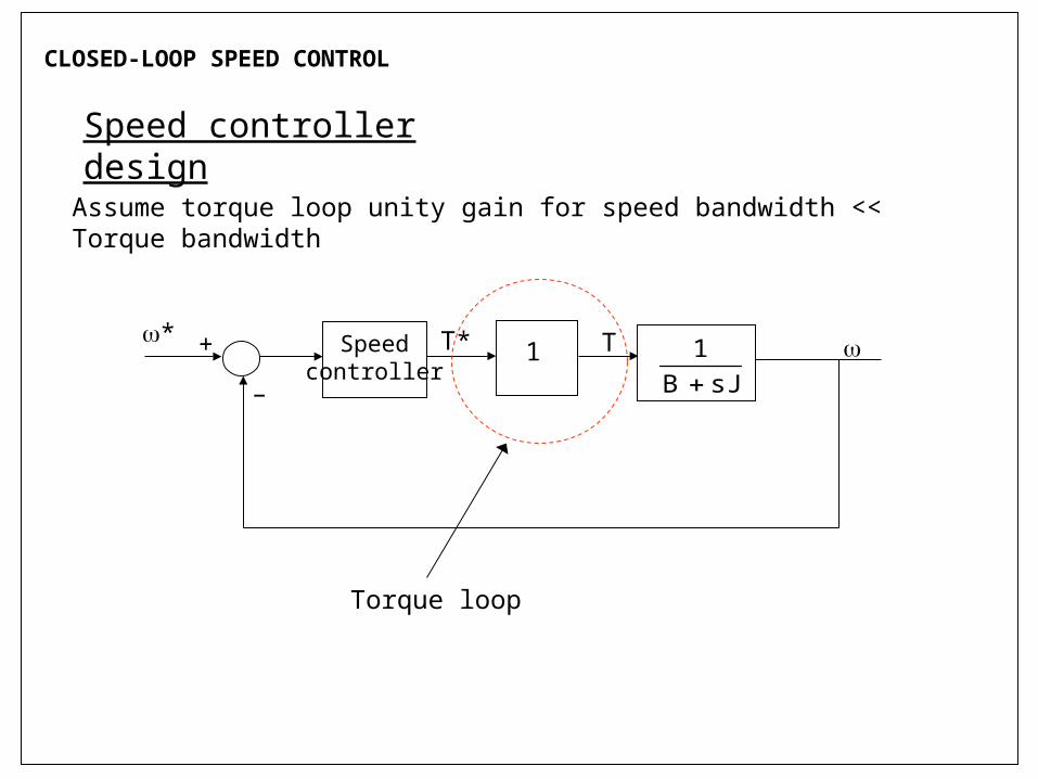
CLOSED-LOOP SPEED CONTROL
Speed controller design
Assume torque loop unity gain for speed bandwidth << Torque bandwidth
1Speedcontroller sJB
1
* T* T
–
+
Torque loop
Bode Diagram
Frequency (Hz)
-50
0
50
100
150From: Input Point To: Output Point
Mag
nitu
de (
dB)
10-2
10-1
100
101
102
103
104
-180
-135
-90
-45
0
Pha
se (
deg)
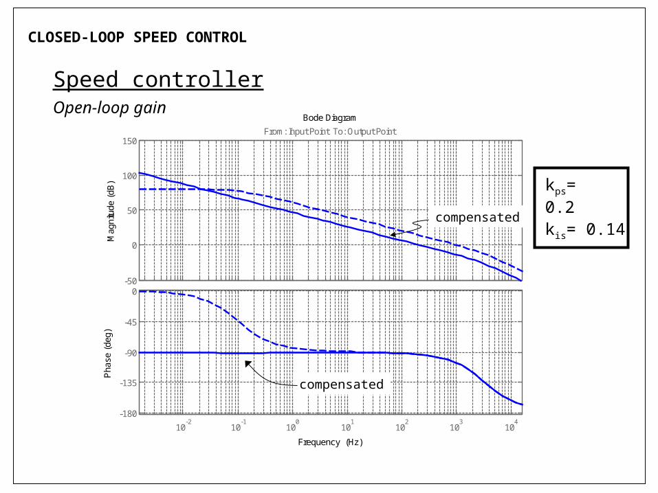
CLOSED-LOOP SPEED CONTROL
Speed controllerOpen-loop gain
compensated
kps= 0.2
kis= 0.14
compensated
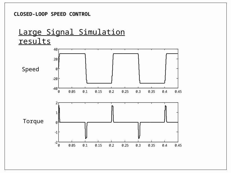
CLOSED-LOOP SPEED CONTROL
Large Signal Simulation results
0 0.05 0.1 0.15 0.2 0.25 0.3 0.35 0.4 0.45-40
-20
0
20
40
0 0.05 0.1 0.15 0.2 0.25 0.3 0.35 0.4 0.45-2
-1
0
1
2
Speed
Torque
CLOSED-LOOP SPEED CONTROL – DESIGN EXAMPLE
SUMMARY
Power electronics converters – to obtain variable armature voltage
Phase controlled rectifier – small bandwidth – large ripple
Switch-mode DC-DC converter – large bandwidth – small ripple
Controller design based on linear small signal model
Power converters - averaged model
DC motor – separately excited or permanent magnet
Closed-loop speed control design based on Bode plots
Verify with large signal simulation
Speed control by: armature voltage (0 b) and field flux (b)