Embed Size (px)
Citation preview

• Editorial-Chief
Kiyoshi Sakai • Editorial Advisors
Toshio Masujima Maki Ikegami Makoto Egashira Chikao Nishida Hideaki Okada Yoshiki Hama Tetsuyuki Yanase Takefumi Tsukada Tatsuya Ichihashi Masato Nagasawa Daisuke Kawai Masato Oshita Toshihiro Kurita
• Vol. 144 Feature Articles Editor
Tetsuyuki Yanase • Editorial Inquiries
Kiyoshi Sakai Corporate Total Productivity Management & Environmental Programs Fax +81-3-3218-2465
• Product Inquiries
Tetsuyuki Yanase Engineering Planning Dept. Building Systems Group Fax: +81-3-3218-2990 Mitsubishi Electric Advance is published on line quarterly (in March, June, September, and December) by Mitsubishi Electric Corporation. Copyright © 2013 by Mitsubishi Electric Corporation; all rights reserved. Printed in Japan.
The company names and product names described herein are the trademarks or registered trademarks of the respective companies.
CONTENTS
Technical Reports
Overview ..........................................................................................1 by Masami Yoshikawa Comfort of Ultra-high Speed Elevators ........................................2 by Masaji Iida and Yoichi Sakuma Energy Saving Technologies for Elevators ..................................6 by Junichiro Ishikawa, Kazuhiro Banno and Sakurako Yamashita Energy Saving Technology for Escalators .................................11 by Ryota Nishioka and Koji Yoshida Lighting Control System Using Human Location Data for Energy Saving ............................................................................................15 by Naoki Kuwahara
MITSUBISHI ELECTRIC
Dec. 2013 / Vol. 144
Elevators and Building Systems
Precis
Elevators and escalators which are indispensible for vertical urban transportation, and energy saving technology which is essential for sustained growth of society. Regarding these features, Mitsubishi Electric’s activities in this field are described.
*Vice President, Corporate Building System Group Mitsubishi Electric ADVANCE December 2013 1
TECHNICAL REPORTS
Overview
Author: Masami Yoshikawa*
The world population is growing and urbanization is advancing. Accordingly, buildings are becoming larger and taller, and so elevators and energy monitoring and control systems are becoming increasingly important for supporting a comfortable and convenient urban lifestyle. In order to improve convenience and comfort for people coming and going inside a building and also for the economy of the building, elevators are being made larger and faster, while there is also demand for improving energy efficiency without loss of comfort.
This issue describes the energy-saving technologies employed in our elevators, technologies for suppressing vibration and noise in the latest ultra-high-speed elevators, and technologies for building control systems which detect the dynamic state of people in a building, thereby improving energy saving.

*Inazawa Works 2
TECHNICAL REPORTS
Comfort of Ultra-high Speed Elevators Authors: Masaji Iida* and Yoichi Sakuma*
1. Introduction
In recent years, buildings in overseas countries have become very tall, with some exceeding 800 m in height. There are also buildings being planned that will be more than 1 km tall. As buildings become taller, there is growing demand for elevators that travel faster. To meet these demands, Mitsubishi Electric has devel-oped an ultra-high-speed elevator capable of traveling at 1,080 m/min, which is considerably faster than the 750-m/min elevator developed by us in the past. During the development of faster elevators, we faced many issues that did not appear in the conventional speed range, and also issues arising due to the ultra-high lift.
This paper focuses on the comfort of ul-tra-high-speed elevators, and describes measures for suppressing vibration inside the car, measures for reducing noise inside the car, and methods of mitigating the sensation of compression in the ears experienced by persons riding the elevator. It also introduces issues peculiar to an ultra-high-speed elevator related to these technologies, and the development of elemental tech-nologies for overcoming these issues.
2. Technology for Suppressing Vibration
Inside the Car
2.1 Technology for damping vibration in a high-speed elevator When an elevator travels, its guide unit follows a
rail installed in the hoistway, so any minute curvature of the rail itself or minute buckling of the rail joints will exert an excitation force on the car. With high-speed elevators in the past, good riding comfort was achieved by improving the machining accuracy of the rail itself, and also by controlling installation accuracy and using passive dampers. With the appearance of the active roller guide in 2003, it became possible to offer greater riding comfort than that of conventional high-speed elevators by using an actuator to cancel out the excita-tion force on the rail.
Although an active roller guide is also used in the recently-developed ultra-high-speed elevator, the vibra-tion mode accompanying the higher speed was an issue. Conventional active control involves controlling the speed region in which the car frame and the car move in the same phase. In the system, vibration was detected by an acceleration sensor installed on the car frame, and was controlled by an active roller guide
mounted on the car frame. However, when active con-trol of an ultra-high-speed elevator is used, the speed reaches the region where the car frame and the car move in opposite phases; as a result, control that is simply an extension of the conventional speed control method cannot be used. It was therefore necessary to construct a new control system. The following sections of this paper describe each issue and its solution.
2.2 Issues related to ultra-high-speed (1)
The frequency of the excitation received by the elevator from the rail is determined by the correlation between the elevator speed and the length of the rail (V/L), as shown in Table 1. Conventionally, the center of the excitation frequency range is about 2.5 Hz. How-ever, at higher speeds, it will shift to the high-frequency side and become about 3.5 Hz. This value is the excita-tion frequency corresponding to the case where the rail is warped in the shape of a bow. When the elevator travels along a rail that is warped in a complicated shape such as an “S” or “W” shape, the excitation frequency will shift even further to the high-frequency side.
Table 1 Frequency of excitation transmitted from the rail Speed V
(m/sec) Rail length
L (m) Excitation
frequency (Hz)Ultra-high-speed
(conventional elevator)12.5 5.0 2.5
Ultra-high-speed (developed elevator)
18.0 5.0 3.6
Looking at the configuration of an elevator car, the
car frame is supported by the rail with vibra-tion-damping material between them, and also the car is supported by the frame via isolating rubber, resulting in a complicated vibration mode. Figure 1 shows an example of the results of analysis. The vibration modes of the car frame and the car are in-phase at low speed, and in opposite phases at ultra-high-speed. Conven-tional vibration suppression involves suppressing the vibration of the car in which the vibration of the car frame is observed and its vibration is damped, thereby suppressing the vibration of the car, which is generated in the same phase as the car frame. Consequently, in order to effectively suppress vibration, it is necessary to detect the vibration of the car.

Mitsubishi Electric ADVANCE December 2013 3
TECHNICAL REPORTS
Fig. 1 Example of analysis of vibration mode
Solid lines: Displacement direction, Broken lines: Initial condition
2.3 Issues related to ultra-high-speed (2)
When an elevator travels at high speed, not only does noise inside the car increase, but also an excita-tion force due to wind pressure acts on it, as described below. When a single elevator is operating independ-ently of other elevators, it is not greatly affected by these forces, but if it passes an adjacent elevator at high speed, a wind force of several hundred N will act on the sides of the car, so it is necessary to devise measures to minimize isolated horizontal vibration.
2.4 Active roller guide for ultra-high-speed use
An active roller guide for an ultra-high-speed ele-vator involves the use of acceleration sensors installed on both the car and the car frame (Fig. 2). These en-able the vibration of the car to be suppressed in an observable condition. The system can therefore mini-mize the effects of changes in the vibration mode of the car from low speed to ultra-high-speed, and also the excitation force due to wind which acts directly on the car. In addition, the roller guide proper and the linear motor-type actuator are optimally designed for ul-tra-high-speed use.
As a result of this system, the riding quality which significantly deteriorated at high speed can be improved to the same level as that using conventional active vibration suppression, when the elevator is accelerating and decelerating and also traveling at the maximum speed of 1,080 m/min.
Fig. 2 Ultra-high-speed active roller guide
3. Technology for Reducing Noise in the Car
The noise level in the car in a moving elevator in-creases in proportion to the speed. Noise inside the car is classified into solid propagation noise due mainly to excitation from the cables and the rail, and air propaga-tion noise in which fluid noise (wind noise) propagates in the air in the vicinity of the car. As the speed of the elevator rises into the ultra-high-speed (exceeding 750 m/min) region, the predominant noise inside the car tends to be fluid noise. This fluid noise is estimated to be proportional to between the 5th and 6th power of the elevator speed. It is estimated that if the car of an ex-isting Mitsubishi elevator designed to run at up to 750 m/min is made to travel at 1,080 m/min, for example, the level of noise inside the car would increase by approximately 10 dB (A). The question of how to reduce this increase of approximately 10 dB (A) was a techni-cal issue related to the current development of an ul-tra-high-speed elevator.
Technology for reducing the noise generated in the car of an ultra-high-speed elevator involves the follow-ing two themes: (1) A method of reducing the noise source in the vicin-
ity of the car (2) Improvement of soundproofing of the car structure
The technical issues related to these themes and also the details of the development process for solving these issues are described below.
3.1 Mechanism of noise generation in the vicinity
of the car Generally, the major source of noise is pressure
fluctuation. For this reason, the first step in this devel-opment was to study an external profile that minimized pressure fluctuations. Specifically, we studied the ideal flow line profile which caused the air striking the end of the air rectification cover at the top of the car to flow to the rear of the car while minimizing separation of the flow from the air rectification cover and the surface of the car, when the elevator was traveling at high speed. In the case of the conventional structure, the upper air rectification cover has a curved external profile and a horizontal end. In addition, the upper beams of the car frame protrude outward, so this structure tended to cause the air flow above the car to become turbulent. To overcome this, we studied the ideal outer profile focusing on optimizing the flow line profile at the end of the air rectification cover, and also on minimizing the protrusions around the car.
3.2 Searching for sources of noise around the car
There are many large and small protrusions around the elevator car. While the elevator is traveling, the air flowing around the car separates at these pro-
Car frame
Car

4
TECHNICAL REPORTS
trusions, resulting in the formation of vortices. At these points, large pressure fluctuations occur, which act as noise sources. To prevent this, it was necessary to determine the points that constituted major sources of noise, and to devise countermeasures in advance. The points where there were large fluctuations of pressure acting on the air flowing around the car were found by numerical fluid simulation, and the noise level in the vicinity of these places was verified by wind tunnel tests on a scale model of the elevator car. The results showed that the major noise sources in the vicinity of the car were located near the active roller guide in-stalled at the top end of the car.
3.3 Reduction of noise around the car
As mentioned above, the main method of reducing noise generated around the car is to install streamlined air rectification covers for correcting the airflow, so the streamlined shape was optimized. In addition, coun-termeasures for the vicinity of the active roller guide, which was found to be a source of noise in the ul-tra-high-speed region, were also studied. Numerical fluid simulation was used to study the streamlined profile of the air rectification covers, and several pat-terns of car profiles with air rectification covers of dif-ferent lengths, different end profiles and different radii of curvature were created and used to perform calcula-tions (Fig. 3).
Fig. 3 Flow of air around the car As a result, it was found that the maximum air cor-
rection effect was obtained by covering the equipment at the top of the car, including the upper beams pro-truding from the top of the car frame, with an air rectifi-cation cover. Also, in order to disperse the pressure acting on the end of the air rectification cover, the end of the cover was changed to a sharp edge. As a result, it was necessary to make the air rectification cover longer than that of the conventional structure, and the ideal streamlined profile was determined. Also, as a countermeasure for noise in the vicinity of the active roller guide, a small active roller guide cover for the equipment at the top of the car was newly developed. By adding the upper air rectification cover to the active
roller guide cover, the air flow in the vicinity of the mov-ing active roller guide is efficiently directed to the rear, thus eliminating noise sources.
From the above, the outer shape of the air rectifi-cation cover was optimized and also countermeasures against noise sources in the vicinity of the car were implemented, resulting in the super-streamlined profile shown in Fig. 4. By covering the equipment at the top of the car with an air rectification cover shaped so as to minimize protruding parts, and by combining the new active roller guide cover with the upper air rectification cover, the ideal streamlined shape around the car was obtained. This is the main feature of this structure. The optimized air rectification cover is about 1.4 times longer than the conventional structure, thus significantly reducing pressure fluctuations around the car.
Fig. 4 Outline profile of car
3.4 Development of a soundproof car interior The riding comfort of passengers in an elevator
(noise inside the car) traveling at high speed is greatly affected by the extent to which noise can be prevented from entering the car. One solution is to use technologies for improving the soundproofing of the car. Because external noise increases in proportion to the speed of the car, an ultra-high-speed elevator requires even better soundproofing. Generally, in order to improve the sound-proofing of the car, it is necessary to increase the weight of the car by using thicker structural members. However, this adversely affects the elevator system and cannot easily be used. To overcome this problem, we focused on the distance between the two sheets (air gap) com-prising the double-walled structure of the car interior wall, and studied ways to improve the soundproofing by in-creasing this air gap. As a result, we succeeded in im-proving the soundproofing performance of the car without increasing its weight. In addition to the improved sound-proof performance of the car interior walls, the airtight-ness around the car doors has been enhanced com-pared with the conventional structure, resulting in im-
Flow lines
Air rectifica-tion cover
Car
Upper air rectification cover
Lower air rectification cover
Active roller guide cover
Mitsubishi Electric ADVANCE December 2013 5
TECHNICAL REPORTS
proved soundproofing of the entire interior. An evaluation of the car interior of an actual elevator employing this structure was carried out, and the results showed that the target noise value for 1,080 m/min was attained.
4. Mitigation of Sensation of Compression
in the Ears In the case of an elevator intended for an ul-
tra-high-rise building or tower, it is not possible to ignore the unpleasant sensation in the ears, or “sensation of compression,” which occurs when a person is riding the elevator. This unpleasant sensation in the ears occurs when the eardrum expands due to a difference between the outside pressure and the pressure in the middle ear, as a result of fluctuations in the surrounding pressure. Because an elevator moves in the vertical direction, the sensation of compression in the ears occurs due to the pressure difference arising from the change in altitude when the elevator is ascending or descending (for example, for a building that is 500 m tall, the pressure difference between the top and bottom floors is about 6,000 Pa). Because this sensation occurs due to the difference in atmospheric pressure, it depends greatly on the lift of the elevator (the height of the building), yet it is not possible to eliminate it completely. Accordingly, in order to reduce this unpleasant sensation even a little, a method of controlling the pressure change (atmos-pheric pressure change lines) inside the elevator car was independently developed. Also, an atmospheric pressure control unit which controls the pressure inside the car along these pressure change lines was newly developed, and was refined to the stage of commercial production to mitigate the sensation of compression in the ears.
5. Conclusion
This paper focused on riding comfort in ul-tra-high-speed elevators. It covered the suppression of car vibration, countermeasures for reducing noise in the car, and the development of measures for reducing the sensation of compression in the ears. The following conclusions were obtained.
To suppress vibration inside the car, an active roller guide for ultra-high-speed elevators was developed, thus attaining the same degree of riding comfort as by conventional active control.
To reduce noise inside the car, the shape of the air rectification cover was optimized, and noise reduction measures in the vicinity of the car and noise-proofing of the car itself were carried out, thus attaining the target noise value at a speed of 1,080 m/min.
To mitigate the sensation of compression in the ears experienced by passengers, air pressure change lines and an atmospheric pressure control unit were developed and commercialized.
References (1) TERAZONO Narihiro, MATSUKURA Yoshitaka:
“Elevator Hitech Technology – Aiming at Realizing the World’s Fastest Elevator,” Ohmsha, pp. 95–99 (1994)
(2) UTSUNOMIYA Kenji, OKAMOTO Ken’ichi, YU-MURA Takashi, SAKUMA Yoichi: “Vibration Control of High-speed Elevators Taking Account of Elec-tricity Consumption Reduction,” Vol. C of the col-lected papers of The Japan Society of Mechanical Engineers, No. 719 (2006), pp. 2048–2055
(3) FUNAI Kiyoshi, et al: “Analysis of Tympanic Mem-brane Behavior and Ear Block Discomfort for Super High Speed Elevators” (Elevator, Escalator and Amusement Rides Conference), Elevator, Escala-tor and Amusement Rides Conference 2005
*Inazawa Works 6
TECHNICAL REPORTS
Energy Saving Technologies for Elevators Authors: Junichiro Ishikawa*, Hirokazu Banno* and Sakurako Yamashita*
1. Introduction
In recent years, interest in energy saving has been increasing both in Japan and overseas, as well as in creating a low-carbon society. In the building industry too, there are moves to standardize methods for evalu-ating energy saving performance, mandate the report-ing of energy saving performance, and also require the installation of facilities for improving energy saving performance. Amid this changing environment, there is growing competition to develop new devices and tech-nologies in many fields related to energy saving.
In the manufacture and development of elevators, energy saving performance has always been important, and new models have offered improved performance. Because the energy consumed by an elevator varies greatly according to its specifications and type of use, it is difficult to evaluate performance using a standard pattern.
This paper summarizes the trends in energy saving technology for elevators and the power consumption characteristics of elevators that use this technology. It also describes the energy saving technology used in the standard “AXIEZ” elevator, which underwent a model change in June 2011, together with its effectiveness.
2. Transition of Energy Saving Technology
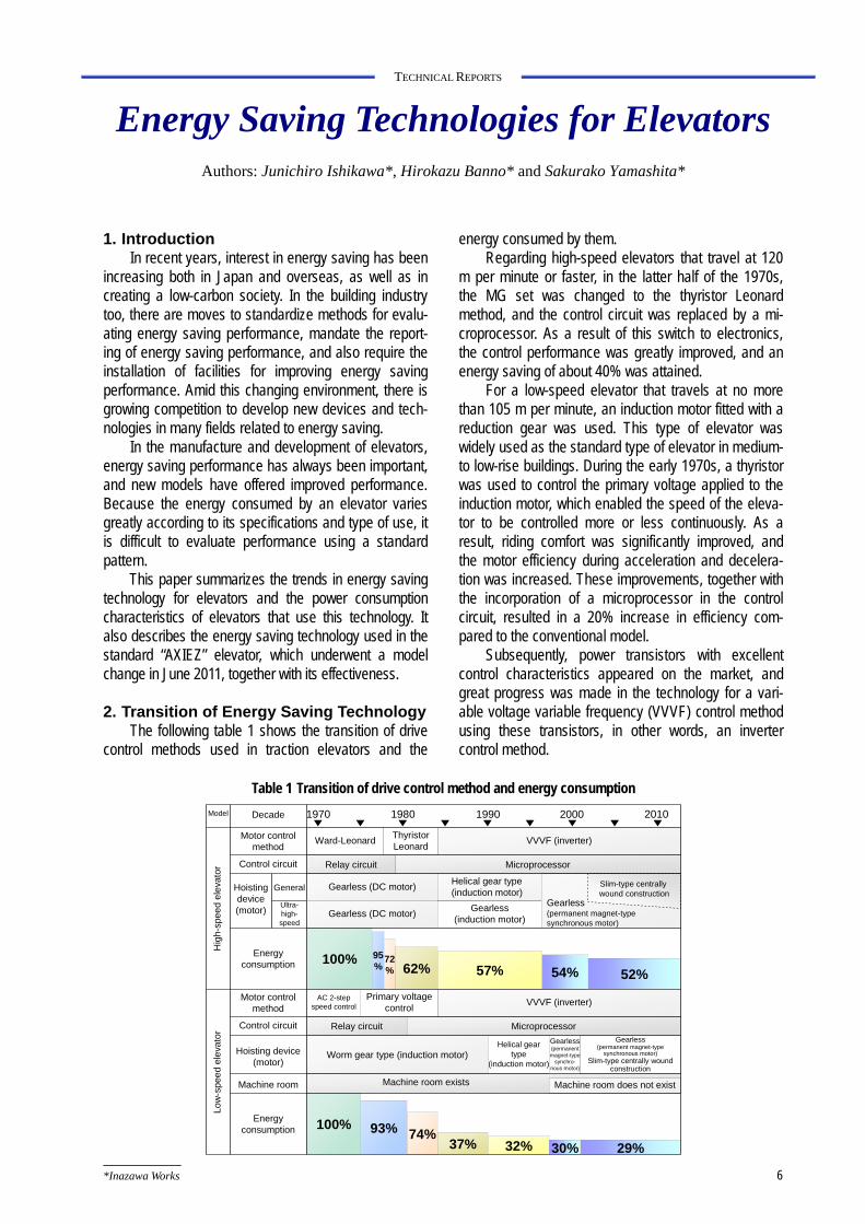
The following table 1 shows the transition of drive control methods used in traction elevators and the
energy consumed by them. Regarding high-speed elevators that travel at 120
m per minute or faster, in the latter half of the 1970s, the MG set was changed to the thyristor Leonard method, and the control circuit was replaced by a mi-croprocessor. As a result of this switch to electronics, the control performance was greatly improved, and an energy saving of about 40% was attained.
For a low-speed elevator that travels at no more than 105 m per minute, an induction motor fitted with a reduction gear was used. This type of elevator was widely used as the standard type of elevator in medium- to low-rise buildings. During the early 1970s, a thyristor was used to control the primary voltage applied to the induction motor, which enabled the speed of the eleva-tor to be controlled more or less continuously. As a result, riding comfort was significantly improved, and the motor efficiency during acceleration and decelera-tion was increased. These improvements, together with the incorporation of a microprocessor in the control circuit, resulted in a 20% increase in efficiency com-pared to the conventional model.
Subsequently, power transistors with excellent control characteristics appeared on the market, and great progress was made in the technology for a vari-able voltage variable frequency (VVVF) control method using these transistors, in other words, an inverter control method.
Gearless(permanent magnet-type
synchronous motor)Slim-type centrally wound
construction
29%32%37%74%93%
100%
MicroprocessorRelay circuit
Decade 1970 1980 1990 2000 2010
Control circuit
Motor control method
Hoisting device (motor)
Machine room
Model
Energy consumption
Hig
h-sp
eed
ele
vato
r
General
Ultra-high-speed
Gearless (DC motor)Helical gear type (induction motor)
Gearless (DC motor)Gearless
(induction motor)
54%57%62%72%
95%
Motor control method
Control circuit Relay circuit Microprocessor
Hoisting device (motor)
100%
Worm gear type (induction motor)Helical gear
type (induction motor)
Machine room exists
Energy consumption
VVVF (inverter)
VVVF (inverter)
Ward-LeonardThyristorLeonard
Primary voltage control
AC 2-step speed control
Machine room does not exist
Gearless(permanent magnet-type synchronous motor)
Slim-type centrally wound construction
52%
Gearless (permanent magnet-type
synchro-nous motor)
30%
Low
-spe
ed
ele
vato
r
Table 1 Transition of drive control method and energy consumption
Mitsubishi Electric ADVANCE December 2013 7
TECHNICAL REPORTS
Ascending
Descending
Time
Power running 100% load 0% load
50% load
0% load
50% load
Regeneration
100% load
Time
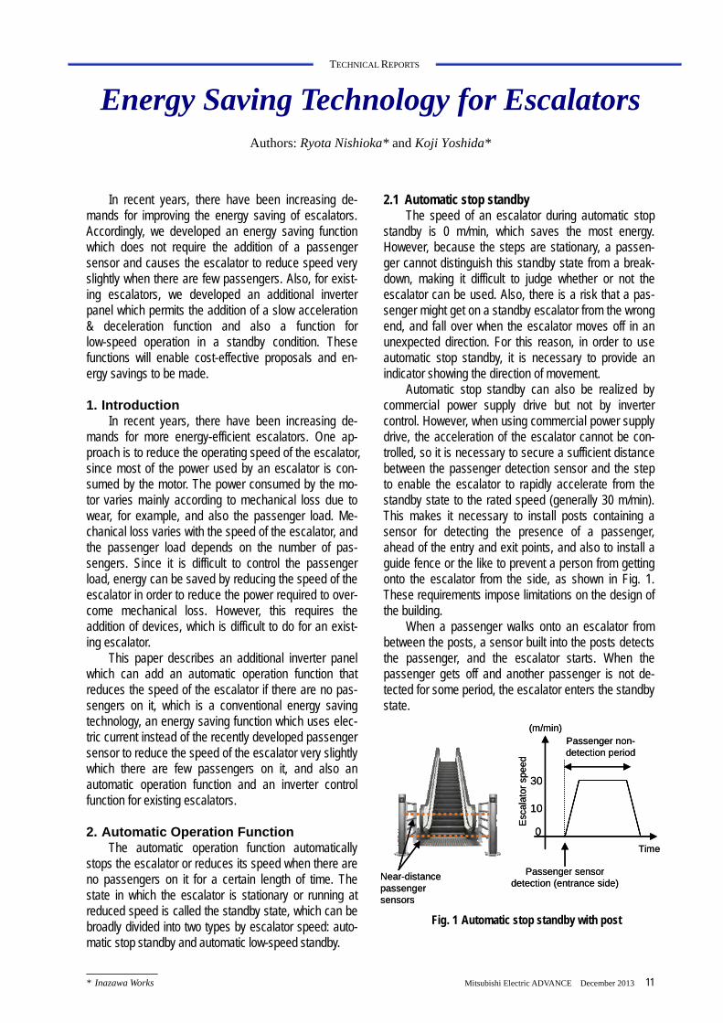
Fig. 2 Power waveform of a hoisting device motor
Rot
atio
nal s
pee
d (%
) P
ower
con
sum
ptio
n (%
)
Mitsubishi was the first company in the world to develop an elevator inverter, and in 1983, succeeded in making a commercially viable high-speed elevator. Inverter control is not only efficient, but also has char-acteristics which improve the power factor of the power source. As a result, it was possible to increase the efficiency by around 10% and also reduce the capacity of the power source facilities in the building by about 20%. In addition, the excellent control performance of this system permitted fine control of even induction mo-tors, thus ensuring excellent riding comfort and highly efficient acceleration and deceleration. Particularly, in the case of a low-speed elevator, it was possible to increase the efficiency by a dramatic 50% compared to the con-ventional primary voltage control method.
In 1990, a helical gear-type hoisting device was commercialized to replace the existing less-efficient worm gear hoisting device, thus improving transmission efficiency and riding comfort.
Around the mid 1990s, a gearless hoisting device incorporating a permanent magnet synchronous motor (hereafter called a “PM gearless hoisting device”) was commercialized for high-speed (at least 120 m/min) and ultra-high-speed (at least 300 m/min) elevators. The use of permanent magnets led to a multi-polar compact motor, which was more efficient than an induction motor.
In 1998, Mitsubishi released an elevator that does not require a machine room. In order to house the hoisting device and the control panel for this elevator inside the hoistway, a very quiet PM gearless hoisting device was adopted for low-speed elevators. To make the control panel slimmer, the drive section and power supply section were closely integrated. Also, a switch-ing power supply was used as the control power supply to ensure a stable power supply voltage and reduce the conversion loss, thus reducing the power consumption.
In 2001, Mitsubishi developed a slim-type PM gearless hoisting device which required even less space and allowed flexibility of layout, resulting in the rapid spread of machine room-less elevators. The motor diameter was increased, its thickness reduced, and a centralized winding construction was employed, significantly reducing copper loss and thus saving energy. At present, the PM gearless hoisting device is the main kind of hoisting device used throughout the entire range from ultra-high speed to high speed. Along with the increasing demand for energy saving, slim hoisting devices using a centralized winding construc-tion are employed for high-speed elevators as well, resulting in energy saving.
In this way, advances in motor drive technology over the past several decades have led to good riding comfort and space saving in elevators, and have also saved energy.
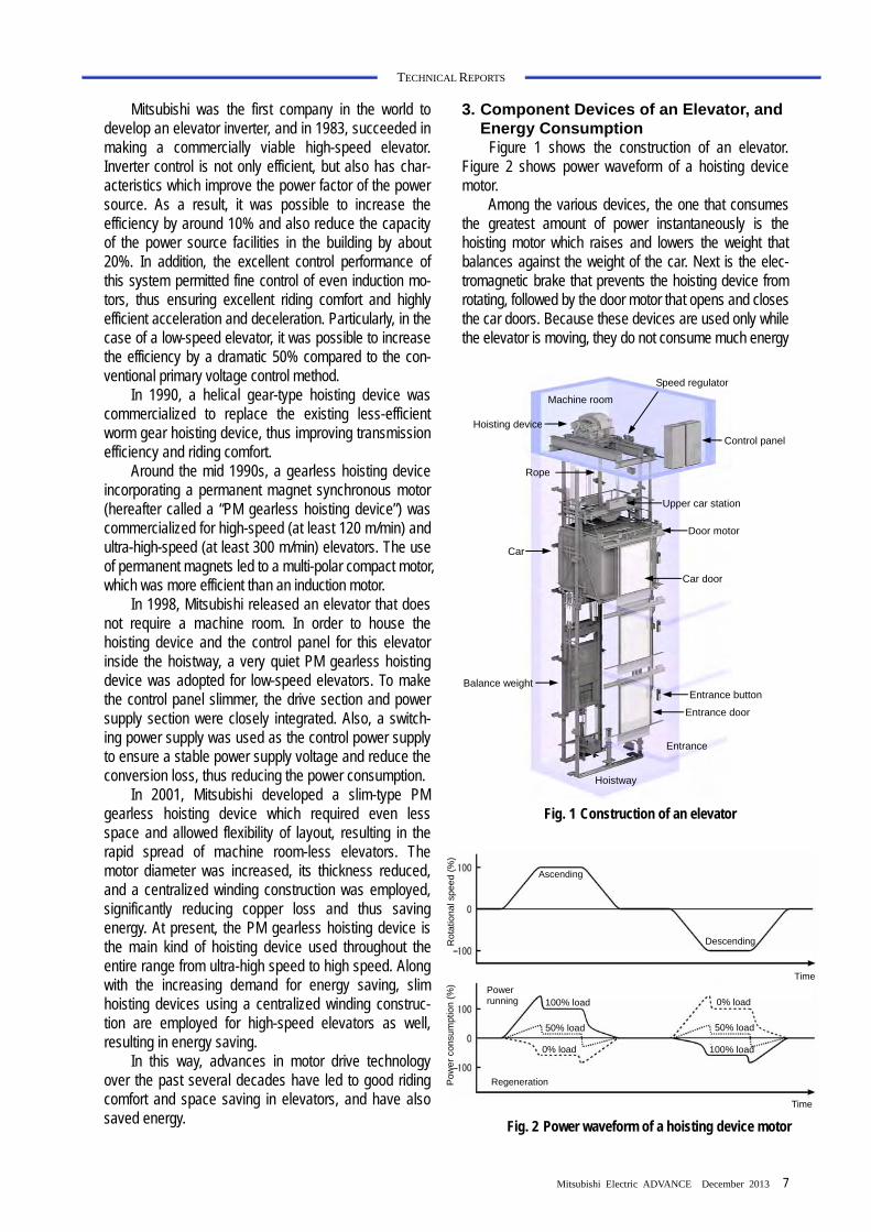
3. Component Devices of an Elevator, and Energy Consumption
Figure 1 shows the construction of an elevator. Figure 2 shows power waveform of a hoisting device motor.
Among the various devices, the one that consumes the greatest amount of power instantaneously is the hoisting motor which raises and lowers the weight that balances against the weight of the car. Next is the elec-tromagnetic brake that prevents the hoisting device from rotating, followed by the door motor that opens and closes the car doors. Because these devices are used only while the elevator is moving, they do not consume much energy
Control panel
Speed regulator
Hoisting device
Car
Rope
Machine room
Hoistway
Entrance
Entrance button
Entrance door
Balance weight
Door motor
Car door
Upper car station
Fig. 1 Construction of an elevator

8
TECHNICAL REPORTS
while the elevator is moving short distances. Figure 3 shows the relationship between the starting
frequency of an elevator and the energy consumed by the devices. Many low-speed elevators are used at low starting frequency. Under this condition, the absolute power consumption is small, but the percentage of the total electrical energy that is consumed continuously by the control devices is large. The lighting remains lit while the elevator is moving and also for a fixed period after it has stopped, so it is lit continuously when the starting frequency is low. Consequently, in the region where the starting frequency is low, the percentage of the total energy consumption is large. The percentage in the case of a hoisting device motor is high in the region where the starting frequency is high.
As shown, the device that affects the total energy consumption changes according to the starting fre-quency. In addition, apart from the starting frequency, the energy consumption also changes according to the specifications of the devices and the car occupancy. These conditions differ greatly from one building to another, and change over time, so it is difficult to evalu-ate the energy saving performance of elevators in different buildings by using a specific representative pattern. Also, in order to effectively reduce the energy consumption under a variety of conditions, it is neces-sary to combine multiple methods according to each starting frequency.
4. “AXIEZ” Energy Saving Technology
4.1 LED lighting
As mentioned above, the power consumed by the lighting of an elevator car is reduced by a function that automatically switches off the lighting after the elevator car stops. Consequently, the lighting in an elevator car is switched on much more frequently than general lighting.
Conventionally, incandescent lamps or fluorescent lamps have been used to illuminate the elevator car, but the life of such lighting appliances depends greatly upon the number of times that they are switched on. For this reason, the lighting is kept on for a fixed period after the elevator stops, thus reducing the number of times that it can be switched on and extending its life. But with this method, the lighting is actually on for longer than necessary, so there is a limit to the energy saving effect of the automatic switch-off function. Re-cently, LED light sources have become cheaper and increasingly popular. One of their main features is that their life is determined mainly by the time during which they are on rather than by the number of times that they are switched on.
All standard “AXIEZ” elevators use LED lighting in the ceiling of the car as the main kind of lighting. As a result, the electric power consumed by the LED ceiling lights is about half of that consumed by conventional fluorescent ceiling lights, and about 1/8 of that con-sumed by incandescent lights. Also, by reducing the time delay until the lamps are automatically turned off, the necessary standby power is reduced. In addition, the life of an LED light is about 3.3 times that of a fluorescent light, and about 26 times that of an incandescent light, thus reducing the lamp replacement frequency.
By increasing the life of the lighting appliances and reducing the energy consumed by them, the life cycle cost and environmental impact are reduced.
4.2 Technology for utilizing energy regeneration
4.2.1 Regenerative converter system
An elevator is suspended by a cable to which a weight is attached that balances against the weight of the car. By driving this cable with a motor, the elevator moves up or down. The balance weight is balanced against the car when the car is occupied by about half
En
erg
y co
nsu
mp
tion
Low Starting frequency High
Pe
rcen
tag
e o
f en
erg
y co
nsu
med
(%
)
Total energy consumption
Percentage occupied by control devices Percentage occupied by lighting Percentage occupied by the hoisting device motor
* The elevator starting intervals are equal for each starting frequency.
Fig. 3 Relationship between the starting frequency of an elevator and the energy consumed

Mitsubishi Electric ADVANCE December 2013 9
TECHNICAL REPORTS
of the rated number of passengers. If this weight bal-ance is upset, the motor will be pulled to the heavier side. As a result, when the heavier side is raised, po-tential energy will be accumulated. Conversely, if the balance weight moves to the side that is pulled, the motor can be used as an electric generator, and the potential energy can be recovered as regenerative energy. In this way, the elevator is designed to capture a large amount of regenerative energy from potential energy in addition to kinetic energy.
High-speed elevators have always made effective use of regenerative energy by using a regenerative converter.
As shown in Fig. 4, the electrical circuit of the ele-vator is designed such that regenerative power returned from the motor is connected directly to the power source system of the building via a regenerative con-verter. This enables the regenerative power to be re-used efficiently.
Most low-speed elevators are installed in small buildings, so it is usually not possible to acquire facili-ties that can adequately consume regenerative electric power, and also there are size and cost limitations, so generally, the regenerative electric power is consumed by a resistor. However, in a medium- to large-scale building, there is currently no solution to this problem, even if there are adequate facilities. To overcome this issue, the regenerative converter of the “AXIEZ” eleva-tor, which does not have a machine room, has been made sufficiently small that it can be installed in the hoistway. It is hoped that in the future, this technology will help save energy in low-speed elevators.
4.2.2 Regenerative electric power storage system
As mentioned above, a regenerative converter of-ten cannot be used in a small building. The ELE SAVE,
which Mitsubishi released in 2001, incorporates a nickel-hydrogen battery which provides enough power to operate the elevator for 10 minutes in the event of a power outage. The battery stores the regenerative electric power, and reuses it while the elevator is run-ning, thus realizing an energy saving of about 20%. This system enables regenerative electric power to be used in small buildings as well.
As a result of recent competition to develop elec-trical storage devices for power applications, the energy density, output density, repeated charging/discharging durability, and charging/discharging efficiency have improved. Among these storage devices, an electrical 2-layer capacitor has excellent repeated charg-ing/discharge durability and high charging/discharging efficiency, and is environment-friendly. The ELE CHARGE regenerative storage system which Mitsubishi has commercialized uses an electrical 2-layer capacitor as the storage device. Although such a capacitor has the abovementioned merits, in order to incorporate it into an elevator, it was necessary to take countermea-sures against deterioration caused by energizing the capacitor at high temperature, and also to design a circuit configuration and control method that made the most of the merits of the capacitor. To resolve these issues, the circuit of the ELE CHARGE was optimized and technology for monitoring the capacitor tempera-ture and voltage was newly developed, thus at least doubling the replacement interval compared with a secondary battery, and also achieving an energy saving effect of about 25% (Fig. 5).
4.3 Energy saving effect
A simulation evaluation of the energy consumed by the energy saving technologies mentioned so far was carried out. The results are shown in Tables 2 and 3.
Phase detection
circuit
Line filter
PS: 3-phase AC power supply
CT: Current detector
PM: Permanent magnet motor
RE: Encoder
PS CT CT
PM AC reactor
ConverterCapacitor
Inverter
Cur
rent
fee
dbac
k
Gate drive circuit
Converter control circuit
Vol
tage
feed
back
Gate drive circuit
Inverter control circuit
Controller
Cur
rent
fee
dbac
k
Car
Bal
ance
w
eigh
t
Rot
or a
ngle
feed
back
Vel
ocity
fee
dbac
k
Fig. 4 Drive system for an elevator with a regenerative converter
RE

10
TECHNICAL REPORTS
The simulation was carried out under the operation conditions in chronological order, based on the meas-urement data of the traffic pattern.
Table 2 shows the energy consumption improve-ment of the “AXIEZ” compared to the conventional model. By adopting energy saving technologies such as LED lighting, the energy consumption can be reduced by up to 20% compared to that of the conventional model. Also, by using LEDs for lighting, which accounts for a large proportion of the energy consumed, auto-matic switching-off of the lights can be optimized. Par-ticularly, in a building where the operation frequency is low, a large energy saving effect will be obtained.
Table 3 shows the energy consumption improve-ment which depends upon whether or not the regenera-tive converter system and/or the regenerative power storage system are used. Compared to when the re-generative converter system is not used, the energy consumption is reduced by up to 35%, and also com-pared to when the regenerative power storage system is not used, the energy consumption is reduced by up to 25%. Also, with both systems, the improvement of energy consumption tends to increase as the number of passengers and also the operation frequency increase.
As mentioned above, the “AXIEZ” delivers excel-lent energy saving performance over a wide range of specifications and applications due to the use of LED lighting and technology for utilizing regeneration.
5. Conclusion
This paper summarized the transition of energy saving technology for elevators and the power con-sumption characteristics of elevators that use this technology. It also described the new technology used in the new “AXIEZ,” and its effectiveness.
Table 2 Improvement of energy consumption of AXIEZ
Application Floor Energy consumption
improvement
5th floor 20% Residence: 9-person elevator 9th floor 18%
5th floor 17% Office: 11-person elevator 10th floor 13%
5th floor 13% Office: 15-person elevator 10th floor 11%
Table 3 Improvement of energy consumption due to
technology for utilizing regeneration
Application Floor Regenerative
converter system improvement
Regenerative electric power storage system
improvement
5th floor 5% 2% Residence: 9-person elevator 9th floor 14% 10%
5th floor 19% 12% Office: 11-person elevator 10th floor 30% 21%
5th floor 30% 25% Office: 15-person elevator 10th floor 35% 20%
In the future, the authors will work on promoting
technologies for utilizing regeneration, and also reduc-ing additional energy consumption caused by each device, in order to help prevent global warming.
6. Reference IKEJIMA Hiroyuki, ARAKI Hiroshi, SUGA Ikuro, TOMI-NAGA Shinji: Mitsubishi Energy Saving-type ELE SAVE Automatic Backup Device for Operating an Elevator in the Event of a Power Failure, Mitsubishi Giho, 75, No. 12, 782−785 (2001)
Electrical 2-layer capacitor
Line filter
PS: 3-phase AC power supply
CT: Current detector
PM: Permanent magnet motor
RE: Encoder
PS CT
PM
ConverterCapacitor
Inverter
Converter
Converter control circuit
Gate drive circuit
Inverter control circuit
Controller
Cur
rent
fee
dbac
k
Car
Bal
ance
w
eigh
t
Rot
or a
ngle
feed
back
Vel
ocity
fee
dbac
k
Fig. 5 Regenerative electric power storage system
RE
* Inazawa Works Mitsubishi Electric ADVANCE December 2013 11
TECHNICAL REPORTS
Energy Saving Technology for Escalators Authors: Ryota Nishioka* and Koji Yoshida*
In recent years, there have been increasing de-mands for improving the energy saving of escalators. Accordingly, we developed an energy saving function which does not require the addition of a passenger sensor and causes the escalator to reduce speed very slightly when there are few passengers. Also, for exist-ing escalators, we developed an additional inverter panel which permits the addition of a slow acceleration & deceleration function and also a function for low-speed operation in a standby condition. These functions will enable cost-effective proposals and en-ergy savings to be made.
1. Introduction
In recent years, there have been increasing de-mands for more energy-efficient escalators. One ap-proach is to reduce the operating speed of the escalator, since most of the power used by an escalator is con-sumed by the motor. The power consumed by the mo-tor varies mainly according to mechanical loss due to wear, for example, and also the passenger load. Me-chanical loss varies with the speed of the escalator, and the passenger load depends on the number of pas-sengers. Since it is difficult to control the passenger load, energy can be saved by reducing the speed of the escalator in order to reduce the power required to over-come mechanical loss. However, this requires the addition of devices, which is difficult to do for an exist-ing escalator.
This paper describes an additional inverter panel which can add an automatic operation function that reduces the speed of the escalator if there are no pas-sengers on it, which is a conventional energy saving technology, an energy saving function which uses elec-tric current instead of the recently developed passenger sensor to reduce the speed of the escalator very slightly which there are few passengers on it, and also an automatic operation function and an inverter control function for existing escalators.
2. Automatic Operation Function
The automatic operation function automatically stops the escalator or reduces its speed when there are no passengers on it for a certain length of time. The state in which the escalator is stationary or running at reduced speed is called the standby state, which can be broadly divided into two types by escalator speed: auto-matic stop standby and automatic low-speed standby.
2.1 Automatic stop standby The speed of an escalator during automatic stop
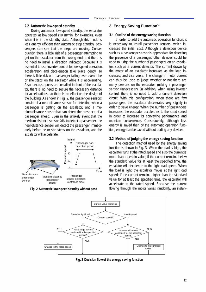
standby is 0 m/min, which saves the most energy. However, because the steps are stationary, a passen-ger cannot distinguish this standby state from a break-down, making it difficult to judge whether or not the escalator can be used. Also, there is a risk that a pas-senger might get on a standby escalator from the wrong end, and fall over when the escalator moves off in an unexpected direction. For this reason, in order to use automatic stop standby, it is necessary to provide an indicator showing the direction of movement.
Automatic stop standby can also be realized by commercial power supply drive but not by inverter control. However, when using commercial power supply drive, the acceleration of the escalator cannot be con-trolled, so it is necessary to secure a sufficient distance between the passenger detection sensor and the step to enable the escalator to rapidly accelerate from the standby state to the rated speed (generally 30 m/min). This makes it necessary to install posts containing a sensor for detecting the presence of a passenger, ahead of the entry and exit points, and also to install a guide fence or the like to prevent a person from getting onto the escalator from the side, as shown in Fig. 1. These requirements impose limitations on the design of the building.
When a passenger walks onto an escalator from between the posts, a sensor built into the posts detects the passenger, and the escalator starts. When the passenger gets off and another passenger is not de-tected for some period, the escalator enters the standby state.
Time
Esc
alat
or s
peed
Passenger sensor detection (entrance side)
Passenger non-detection period
0
30
(m/min)
10
Near-distance passenger sensors
Time
Esc
alat
or s
peed
Passenger sensor detection (entrance side)
Passenger non-detection period
0
30
(m/min)
10
Near-distance passenger sensors
Fig. 1 Automatic stop standby with post
12
TECHNICAL REPORTS
2.2 Automatic low-speed standby During automatic low-speed standby, the escalator
operates at low speed (10 m/min, for example), even when it is in the standby state. Although this mode is less energy efficient than automatic stop standby, pas-sengers can see that the steps are moving. Conse-quently, there is little risk of a passenger attempting to get on the escalator from the wrong end, and there is no need to install a direction indicator. Because it is essential to use inverter control for low-speed operation, acceleration and deceleration take place gently, so there is little risk of a passenger falling over even if he or she steps on the escalator while it is accelerating. Also, because posts are installed in front of the escala-tor, there is no need to secure the necessary distance for accelerations, so there is no effect on the design of the building. As shown in Fig. 2, the passenger sensors consist of a near-distance sensor for detecting when a passenger is getting on the escalator, and a me-dium-distance sensor that can detect the presence of a passenger ahead. Even in the unlikely event that the medium-distance sensor fails to detect a passenger, the near-distance sensor will detect the passenger immedi-ately before he or she steps on the escalator, and the escalator will accelerate.
3. Energy Saving Function*1
3.1 Outline of the energy saving function In order to add the automatic operation function, it
is necessary to install passenger sensors, which in-creases the initial cost. Although a detection device such as a passenger sensor is appropriate for detecting the presence of a passenger, other devices could be used to judge the number of passengers on an escala-tor, such as a current detector. The current drawn by the motor of an escalator increases as the load in-creases, and vice versa. The change in motor current can thus be used to judge whether or not there are many persons on the escalator, making a passenger sensor unnecessary. In addition, when using inverter control, there is no need to add a current detection circuit. With this configuration, when there are few passengers, the escalator decelerates very slightly in order to save energy. When the number of passengers increases, the escalator accelerates to the rated speed in order to increase its conveying performance and maintain convenience. Consequently, although less energy is saved than by the automatic operation func-tion, energy can be saved without adding any devices.
3.2 Method of judging the energy saving function
The detection method used by the energy saving function is shown in Fig. 3. When the load is high, the escalator runs at the rated speed and also the current is more than a certain value; if the current remains below the standard value for at least the specified time, the escalator will decelerate to the light load speed. When the load is light, the escalator moves at the light load speed; if the current remains higher than the standard value for at least the specified time, the escalator will accelerate to the rated speed. Because the current flowing through the motor varies randomly, an instan-
Fig. 3 Decision flow of the energy saving function
Current value sampling
Current speed?
Has a small current continued for the specified
period?
Has a large current continued for the specified
period?
Change to the rated speed. Change to the light load speed.
Rated speedSpeed at light load
YES
NONO
YES
Fig. 2 Automatic low-speed standby without post
Time
Esc
alat
or s
peed
Passenger sensor detection (entrance side)
Passenger non-detection period
0
30
(m/min)
10
Medium-distance passenger
sensor
Near-distance passenger sensor
Mitsubishi Electric ADVANCE December 2013 13
TECHNICAL REPORTS
taneous value and also a judgment time for the speci-fied time are set in the escalator, and the control system changes the speed of the escalator after it has ade-quately confirmed that the load has varied. By setting the judgment time for accelerating to the rated speed to a slightly short value, and setting the judgment time for decelerating to the light load speed to a slightly long value, there is no loss of convenience, and also the escalator does not frequently and repeatedly accelerate and decelerate while there are passengers on it. *1 This function is sold only in Japan.
4. Additional Inverter Panel
4.1 Outline of additional inverter panel
When an automatic operation function is to be added to an escalator that is driven by an existing commercial power supply, it is sometimes difficult to install posts or direction indicators that may involve making changes to the building. Conversely, if an in-verter control function is to be added, it will be neces-sary to replace either the control system or the entire escalator, which would take a long time for renovation and put the escalator out of use.
For this reason, the additional inverter panel was designed to enable the inverter control function and also automatic functions such as the incorporation of a passenger sensor to be added to an existing escalator. Because an inverter control function is to be added, posts and direction indicators are unnecessary. Also, this method is cheaper than replacing the control sys-tem or the escalator. In addition, because the existing control system can be used, the circuit can be modified easily and quickly.
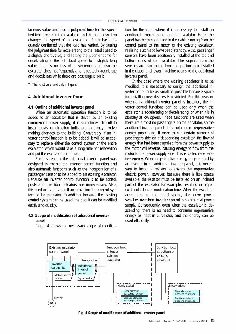
4.2 Scope of modification of additional inverter
panel Figure 4 shows the necessary scope of modifica-
tion for the case where it is necessary to install an additional inverter panel on the escalator. Here, the panel has been connected in the cable running from the control panel to the motor of the existing escalator, realizing automatic low-speed standby. Also, passenger sensors have been additionally installed at the top and bottom ends of the escalator. The signals from the sensors are transmitted from the junction box installed in the upper and lower machine rooms to the additional inverter panel.
In the case where the existing escalator is to be modified, it is necessary to design the additional in-verter panel to be as small as possible because space for installing new devices is restricted. For this reason, when an additional inverter panel is installed, the in-verter control functions can be used only when the escalator is accelerating or decelerating, or when it is in standby at low speed. These functions are used when there are almost no passengers on the escalator, so the additional inverter panel does not require regenerative energy processing. If more than a certain number of passengers ride on a descending escalator, the flow of energy that had been supplied from the power supply to the motor will reverse, causing energy to flow from the motor to the power supply side. This is called regenera-tive energy. When regenerative energy is generated by an inverter in an additional inverter panel, it is neces-sary to install a resistor to absorb the regenerative electric power. However, because there is little space available, the resistor must be installed on an inclined part of the escalator for example, resulting in higher cost and a longer modification time. When the escalator accelerates to the rated speed, the drive power switches over from inverter control to commercial power supply. Consequently, even when the escalator is de-scending, there is no need to consume regenerative energy as heat in a resistor, and the energy can be used efficiently.
Fig. 4 Scope of modification of additional inverter panel
M
Additional interval panel
Signal cableMotive power cables
Motor
Newly added
Existing escalator control panel
Near-distance passenger sensor
Medium-distance passenger sensor
Near-distance passenger sensor
Newly added
Medium-distance passenger sensor
Junction box at top of existing escalator
Inverter output filter
Junction box at bottom of existing escalator
Newly added

14
TECHNICAL REPORTS
Table 1 Comparison of functions
Function Control system
Necessary device Energy
saving per-formance*2
Automatic stop standby
Commercial power supply drive inverter
Passenger sensor
Direction indicator
High (Approx.
26%)
Automatic low-speed
standby Inverter Passenger sensor
Medium (Approx.
16%)
Energy saving operation
Inverter – Low
(Approx. 7%)
(Table 1 is based on a floor height of 5 m, 500 passengers/hour, and 15 hours of operation.)
*2 The effectiveness differs according to the calculation conditions.
5. Energy Saving Performance
Table 1 shows a summary of the control systems that can be realized for the automatic operation function and the energy saving function, the necessary devices for these systems and functions, and also the corre-sponding energy saving effectiveness. The greatest energy saving is obtained by using the automatic stop standby, because the change from the rated speed to the standby speed is greatest. This system not only permits inverter control, but also commercial power supply drive. On the other hand, it is necessary to add passenger sensors and direction indicators. Also, in the case of commercial power supply drive, there are addi-tional restrictions such as the necessity of installing posts. Inverter control is necessary for the automatic low-speed standby and energy saving functions. Direc-tion indicators are unnecessary, but because the change from the rated speed is small, less energy is saved than with automatic stop standby. Although the energy saving function is inferior to the automatic op-eration function in respect of energy saving perform-ance, it does not require the installation of additional devices.
6. Conclusion
The demand for energy saving will continue to in-crease. The authors consider that the technologies described here can save energy not only on newly installed escalators but also on existing escalators, and also enable energy to be saved according to the instal-lation environment.

*Total Security Systems Dept. Building Systems Group Mitsubishi Electric ADVANCE December 2013 15
TECHNICAL REPORTS
Lighting Control System Using Human Location Data for Energy Saving
Author: Naoki Kuwahara*
1. Introduction
Mitsubishi Electric offers solutions centered on se-curity, under the brand name DIGUARD, for various customer problems in buildings, factories, public facili-ties, and so on. As an example, this paper describes the development of an energy saving system that coor-dinates security and lighting equipment.
In recent years, as evidenced by revisions to the Energy Saving Law and Tokyo Metropolitan Ordinances, the importance of energy saving measures in offices is increasing. Particularly since the accident at the Fuku-shima Dai-ichi Power Station of Tokyo Electric Power Company, there has been a shortage of electricity, and so there is an urgent need for measures to save electric-ity in offices, and for maintaining and improving produc-tion and services using less electric power.
One way to save electricity and energy is to use low-power devices such as LED lighting and inverter control devices, but it is also important to reduce un-necessary electricity consumption. Accordingly, Mitsu-bishi Electric is developing a system that uses informa-tion concerning the locations of people (“who” is located “where”) in order to minimize the unnecessary use of lighting and air conditioning equipment, thereby saving electricity and energy. This paper describes a system coordinated with lighting equipment, which is proposed jointly with Mitsubishi Jisho Sekkei Inc. First, a location management system to identify the locations of people in a building, and a lighting control system that utilizes the location information, are described. Tests carried out on these coordinated systems, and the results, and then described.
2. Location Management System
If a location management system can identify the locations of people in a building, it can be used to pro-vide a variety of services. For example, it could offer various location based services (LBS) to reduce the consumption of electricity, as described in this paper, improve security and signage, and also protect people in a disaster. In the past, access control systems for controlling the locations of people in a building used information on whether or not people were present. However, these systems could not identify the location of a person inside a room. We therefore focused on a hands-free (HF) access control system(1) employing
wireless tags, which can recognize when a tag is brought near an antenna of the system, and developed a location management system that can determine the location of a particular person by capturing their tag data using antennas installed within the room (Fig. 1). Because this system uses the same tags as used for access control, location can be detected without placing additional burden on the user. Table 1 shows the dif-ference between the new system and the previous HF access control system. Whereas an access control system controls the passage of a person past an en-trance as a point, a location management system con-trols movement over a plane which straddles multiple antennas. However, a location management system cannot perform detection using a single antenna, or it must perform simultaneous detection from multiple antennas. To overcome this, our system has functions such as a timeout function which presumes that if detec-tion fails within a certain time, the object to be detected is deemed to be absent, and also a function that estimates the location of the object in the case of multiple detection operations by multiple antennas.
Table 1 Comparison between the location management system and HF access control system
HF access control system Location manage-
ment system Aim/Main func-tion
Control of the passage of a person through a doorway
Location management for each ID
Antenna location Near an entrance Located throughout the room
Measures against detection failure and multiple detection
Timeout function, location estimation function, etc.
Antenna
Office zone
Security system (access control
system)
Location manage-ment system
Fig. 1 Illustration of our location management system
Lighting
Tag
16
TECHNICAL REPORTS
3. Lighting Control System
3.1 Lighting control system that uses location information In the office sections of a building, lighting can ac-
count for as much as 40%(2) of total electricity con-sumption, so it is crucial to switch off all lights when they are not needed. However, typically each ceiling light in an office is shared by multiple workers, so work-ers hesitate to switch off a light that may be needed by coworkers. Also, workers sometimes forget to switch off lights. Consequently, the system should automatically control the office lighting according to whether or not workers are present. As an example of automatic con-trol, a system that uses a power saving sensor has been commercialized, but such sensors often fail to reliably detect the presence or absence of a person, so its use is limited to areas where lighting is shared. Mitsubishi Electric has therefore developed a lighting control system which utilizes passing information output from an access control system, and switches on the ceiling lights in the vicinity when a person enters the room, or switches them off when a person leaves the room, in order to reduce the electricity consumed by lighting(3). Tests have shown the effectiveness of this system for saving electricity, and the system is currently being marketed as an option for the Facima BA System, which is Mitsubishi’s building facility open integrated system. Recently, a location management system was used instead of an access control system to further reduce electricity consumption by grasping the loca-tions of people in a room.
The method of controlling lighting is as follows. A location management system continually senses in which antenna area a tag is located. If the area changes, the ID of the tag for which the change oc-curred and the location of the antenna will be commu-nicated to the lighting control system. If the antenna was near an entrance (entrance to a room), the light
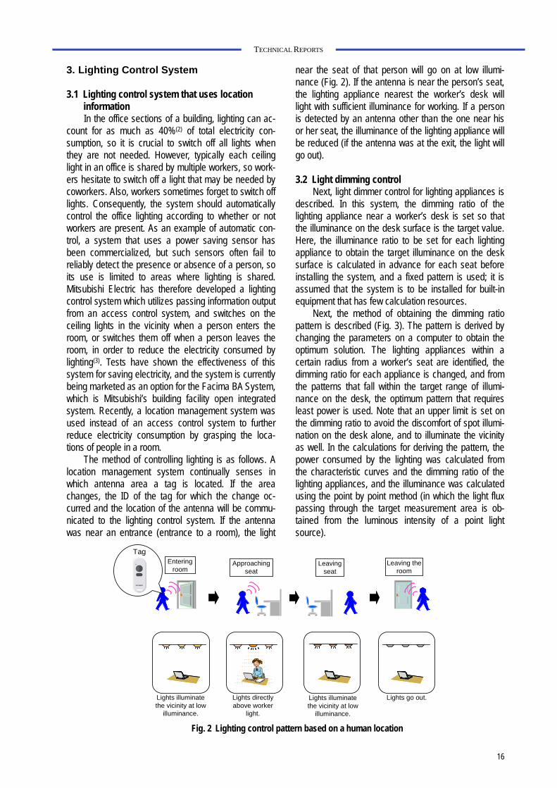
near the seat of that person will go on at low illumi-nance (Fig. 2). If the antenna is near the person’s seat, the lighting appliance nearest the worker’s desk will light with sufficient illuminance for working. If a person is detected by an antenna other than the one near his or her seat, the illuminance of the lighting appliance will be reduced (if the antenna was at the exit, the light will go out).
3.2 Light dimming control
Next, light dimmer control for lighting appliances is described. In this system, the dimming ratio of the lighting appliance near a worker’s desk is set so that the illuminance on the desk surface is the target value. Here, the illuminance ratio to be set for each lighting appliance to obtain the target illuminance on the desk surface is calculated in advance for each seat before installing the system, and a fixed pattern is used; it is assumed that the system is to be installed for built-in equipment that has few calculation resources.
Next, the method of obtaining the dimming ratio pattern is described (Fig. 3). The pattern is derived by changing the parameters on a computer to obtain the optimum solution. The lighting appliances within a certain radius from a worker’s seat are identified, the dimming ratio for each appliance is changed, and from the patterns that fall within the target range of illumi-nance on the desk, the optimum pattern that requires least power is used. Note that an upper limit is set on the dimming ratio to avoid the discomfort of spot illumi-nation on the desk alone, and to illuminate the vicinity as well. In the calculations for deriving the pattern, the power consumed by the lighting was calculated from the characteristic curves and the dimming ratio of the lighting appliances, and the illuminance was calculated using the point by point method (in which the light flux passing through the target measurement area is ob-tained from the luminous intensity of a point light source).
Fig. 2 Lighting control pattern based on a human location
Entering room
Approaching seat
Leaving the room
Tag
Leaving seat
Lights directly above worker
light.
Lights go out.Lights illuminate the vicinity at low
illuminance.
Lights illuminate the vicinity at low
illuminance.

Mitsubishi Electric ADVANCE December 2013 17
TECHNICAL REPORTS
4. Testing and Evaluation
4.1 Testing In order to evaluate our lighting control system,
tests were carried out in one section of the office build-ing of Mitsubishi Electric’s laboratory. Table 2 shows the specifications of the test environment. The test was performed using 66 lighting appliances and 50 people, the desktop illuminance was set to 500 lx when there was a worker at the desk, and to 200 lx when there was no worker. In this test, this system was also employed in the conference room, which is within the target area. To enable the illuminance to be adjusted according to the type of work being carried out, the system was modified so that the illuminance could be changed by pressing a button on the tag. Figure 4 shows an outline of the system. The location management system con-sists of antennas, a controller, and a location detection server. The location detection server manages the location of the tag and transmits any change in location
to the lighting control server. The lighting control server selects a suitable dimmer control pattern for the motion of the tag, and issues a command to the lighting appli-ance by BACnet*1 communication in order to carry out dimmer control. *1 BACnet: A communication protocol standard for a network in an
intelligent building. It is a registered trademark of the American Society of Heating, Refrigerating and Air-Conditioning Engineers (ASHRAE).
4.2 Evaluation results
4.2.1 Power consumption
Figure 5 shows the transition of power consump-tion calculated from the command history of dimmer control used in the test. The plot is the estimated power consumption per day. For reference, the estimated power consumption for normal operation (all lighting appliances are uniformly dimmed to 70% from when the first person enters the office for the day until the last
Door (with electric lock)
Tag
Controller
Sending antenna
Receiving antenna
Location detection server
Ethernet
Lighting equipment
Mel-save NET F lighting control systemMade by Mitsubishi Electric Lighting
Location management systemBACnetcommunication
Lighting control server
Fig. 4 Diagram of the test system
Table 2 Specifications of the experiment environment
Test period From July 1, 2011
Building type Office building
Number of seats 50 seats + 2 conference rooms
Number of lighting appliances
66
Number of antennas 20 (near seats only)
Business type Research department
Working hours 8:30−17:00 (There is overtime work)
Lighting schedule control Lights were off during the mid-day break (12:30−13:00).
Target desktop illuminance 500 lx (when in seat) 200 lx (when absent)
Fig. 3 Derivation of patterns of lighting control
Seat
Illuminance Illuminance
IlluminanceIlluminance
Illuminance Illuminance
Of the patterns where seat illuminance Ix, rfalls within the target area, the combination that minimizes the power Px consumed by the lighting appliance is selected.
Ix, r = f(r)x - It≤ Target rangePx = kx
Target illuminance: ItIllumination dimming ratio: x(xmin ≤ x ≤ xmax)Max. dimming ratio: xmaxMin. dimming ratio: xminIlluminance coefficient: f(r)Distance from the lighting appliance: rPower consumption coefficient: k
Within effective radius
18
TECHNICAL REPORTS
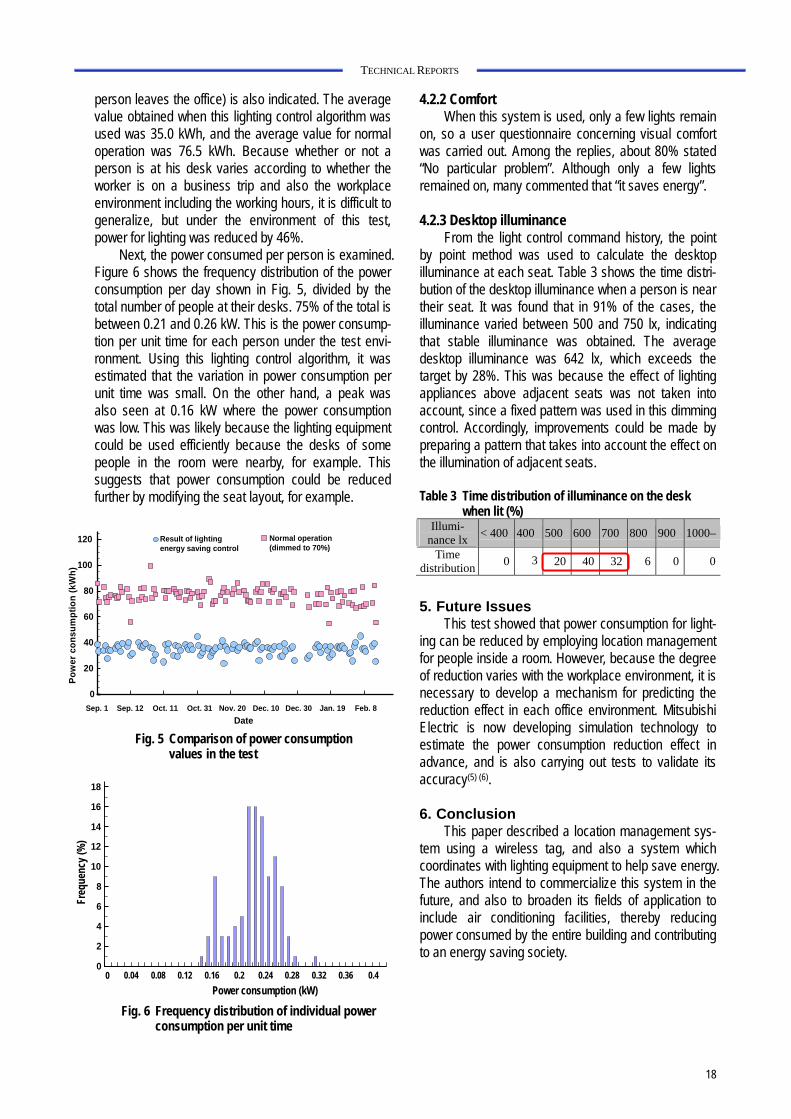
person leaves the office) is also indicated. The average value obtained when this lighting control algorithm was used was 35.0 kWh, and the average value for normal operation was 76.5 kWh. Because whether or not a person is at his desk varies according to whether the worker is on a business trip and also the workplace environment including the working hours, it is difficult to generalize, but under the environment of this test, power for lighting was reduced by 46%.
Next, the power consumed per person is examined. Figure 6 shows the frequency distribution of the power consumption per day shown in Fig. 5, divided by the total number of people at their desks. 75% of the total is between 0.21 and 0.26 kW. This is the power consump-tion per unit time for each person under the test envi-ronment. Using this lighting control algorithm, it was estimated that the variation in power consumption per unit time was small. On the other hand, a peak was also seen at 0.16 kW where the power consumption was low. This was likely because the lighting equipment could be used efficiently because the desks of some people in the room were nearby, for example. This suggests that power consumption could be reduced further by modifying the seat layout, for example.
4.2.2 Comfort When this system is used, only a few lights remain
on, so a user questionnaire concerning visual comfort was carried out. Among the replies, about 80% stated “No particular problem”. Although only a few lights remained on, many commented that “it saves energy”.
4.2.3 Desktop illuminance
From the light control command history, the point by point method was used to calculate the desktop illuminance at each seat. Table 3 shows the time distri-bution of the desktop illuminance when a person is near their seat. It was found that in 91% of the cases, the illuminance varied between 500 and 750 lx, indicating that stable illuminance was obtained. The average desktop illuminance was 642 lx, which exceeds the target by 28%. This was because the effect of lighting appliances above adjacent seats was not taken into account, since a fixed pattern was used in this dimming control. Accordingly, improvements could be made by preparing a pattern that takes into account the effect on the illumination of adjacent seats.
Table 3 Time distribution of illuminance on the desk
when lit (%) Illumi-
nance lx< 400 400 500 600 700 800 900 1000–
Time distribution
0 3 20 40 32 6 0 0
5. Future Issues This test showed that power consumption for light-
ing can be reduced by employing location management for people inside a room. However, because the degree of reduction varies with the workplace environment, it is necessary to develop a mechanism for predicting the reduction effect in each office environment. Mitsubishi Electric is now developing simulation technology to estimate the power consumption reduction effect in advance, and is also carrying out tests to validate its accuracy(5) (6).
6. Conclusion
This paper described a location management sys-tem using a wireless tag, and also a system which coordinates with lighting equipment to help save energy. The authors intend to commercialize this system in the future, and also to broaden its fields of application to include air conditioning facilities, thereby reducing power consumed by the entire building and contributing to an energy saving society.
0
20
40
60
80
100
120
Date
Po
wer
co
nsu
mp
tio
n (
kW
h)
Result of lighting energy saving control
Normal operation (dimmed to 70%)
Sep. 1 Sep. 12 Oct. 11 Oct. 31 Nov. 20 Dec. 10 Dec. 30 Jan. 19 Feb. 8
Fig. 5 Comparison of power consumption values in the test
Fig. 6 Frequency distribution of individual power consumption per unit time
0
2
4
6
8
10
12
14
16
18
0 0.04 0.08 0.12 0.16 0.2 0.24 0.28 0.32 0.36 0.4
Power consumption (kW)
Freq
uenc
y (%
)

Mitsubishi Electric ADVANCE December 2013 19
TECHNICAL REPORTS
References (1) Mitsubishi Electric Giho, August 2012, “Develop-
ment of a Hands-free Access Control System” (2) ECCJ Energy Saving Center, “Energy Saving in Office Buildings”
http://www.eccj.or.jp/office_ bldg/01.html (3) Mitsubishi Electric Giho, September 2009, “Access
Control – Lighting Coordinated Energy Saving Con-trol System”
(4) Mitsubishi Electric Giho, September 2009 “Mitsu-bishi Building Facilities Open Integrated System” (Facima BA System)
(5) Mitsubishi Electric February 16, 2011 Press Re-lease, “Office Building Energy Saving Simulation Technology” was developed.
(6) Mitsubishi Electric June 30, 2011 Press Release, Energy saving test using the “Office Building En-ergy Saving Simulation Technology” commenced.