Embed Size (px)
Citation preview

Dell Precision Workstation T3610Owner's Manual
Regulatory Model: D01TRegulatory Type: D01T004
備註、提醒及警告
備註: 「備註」表示可以幫助您更有效地使用電腦的重要資訊。
警示: 「提醒」說明可能會損壞硬件或導致數據遺失,並告訴您如何避免問題。
警告: 「警告」表示有可能導致財產損失、人身傷害甚至死亡。
© 2015 Dell Inc. 版權所有。本產品受美國和國際版權與智慧財產權法保護。Dell ™及 Dell 徽標是 Dell Inc.在美國和/或其他司法轄區的商標。此處述及的所有其他標誌和名稱可能使其各自公司的商標。
2015 – 05
Rev. A02

1 處理電腦.......................................................................................................................................5Before Working Inside Your Computer............................................................................................................................... 5Turning Off Your Computer................................................................................................................................................. 6After Working Inside Your Computer..................................................................................................................................6
2 卸下和安裝元件.............................................................................................................................7建議的工具.............................................................................................................................................................................7System Overview...................................................................................................................................................................7Removing the Power Supply Unit (PSU)........................................................................................................................... 8Installing the Power Supply Unit (PSU)..............................................................................................................................8Removing the Cover............................................................................................................................................................. 8Installing the Cover................................................................................................................................................................9Removing the PSU Card..................................................................................................................................................... 10Installing the PSU Card........................................................................................................................................................ 11Removing the Front Bezel................................................................................................................................................... 11Installing the Front Bezel.....................................................................................................................................................12Removing the PCI Card.......................................................................................................................................................12Installing the PCI Card......................................................................................................................................................... 12Removing the Optical Drive ............................................................................................................................................... 13Installing the Optical Drive ................................................................................................................................................. 14Removing the Hard Drive....................................................................................................................................................15Installing the Hard Drive ..................................................................................................................................................... 16Removing the Speaker........................................................................................................................................................ 16Installing the Speaker........................................................................................................................................................... 17Installing the Thermal Sensor..............................................................................................................................................17Removing the Thermal Sensor........................................................................................................................................... 17Removing the Input/Output (I/O) Panel.......................................................................................................................... 17Installing the Input/Output (I/O) Panel............................................................................................................................ 19Removing the Air Tunnel .................................................................................................................................................... 19Installing the Air Tunnel ......................................................................................................................................................20Removing the Memory....................................................................................................................................................... 20Installing the Memory..........................................................................................................................................................20Removing the Coin-Cell Battery.........................................................................................................................................21Installing the Coin-Cell Battery...........................................................................................................................................21Removing the System Fan..................................................................................................................................................21Installing the System Fan................................................................................................................................................... 25Removing the Heatsink.......................................................................................................................................................25Installing the Heatsink.........................................................................................................................................................26Removing the Heatsink Fan............................................................................................................................................... 26Installing the Heatsink Fan..................................................................................................................................................27Removing the Processor.................................................................................................................................................... 27Installing the Processor.......................................................................................................................................................27Removing the System Board............................................................................................................................................. 28Installing the System Board................................................................................................................................................29
Contents
Contents 3
System Board Components............................................................................................................................................... 30
3 Additional Information................................................................................................................ 32Memory Module Guidelines................................................................................................................................................32Power Supply Unit (PSU) Lock......................................................................................................................................... 32
4 System Setup............................................................................................................................ 33Boot Sequence (開機順序)............................................................................................................................................... 33Navigation Keys................................................................................................................................................................... 33System Setup Options........................................................................................................................................................34Updating the BIOS ............................................................................................................................................................. 39System and Setup Password.............................................................................................................................................40
Assigning a System Password and Setup Password................................................................................................ 40刪除或變更現有的系統及/或設定密碼.................................................................................................................... 40Disabling a System Password....................................................................................................................................... 41
5 診斷.......................................................................................................................................... 42Enhanced Pre-Boot System Assessment (ePSA) Diagnostics..................................................................................... 42
6 Troubleshooting Your Computer.................................................................................................. 43Diagnostic LEDs...................................................................................................................................................................43Error Messages....................................................................................................................................................................44
7 Technical Specifications............................................................................................................. 46
8 聯絡 Dell.................................................................................................................................... 52
4 Contents

處理電腦主題:
• Before Working Inside Your Computer• Turning Off Your Computer• After Working Inside Your Computer
Before Working Inside Your ComputerUse the following safety guidelines to help protect your computer from potential damage and to help to ensure your personal safety. Unless otherwise noted, each procedure included in this document assumes that the following conditions exist:
• You have read the safety information that shipped with your computer.• A component can be replaced or--if purchased separately--installed by performing the removal procedure in reverse order.
NOTE: Before working inside your computer, read the safety information that shipped with your computer. For
additional safety best practices information, see the Regulatory Compliance Homepage at www.dell.com/
regulatory_compliance
CAUTION: Many repairs may only be done by a certified service technician. You should only perform troubleshooting and
simple repairs as authorized in your product documentation, or as directed by the online or telephone service and
support team. Damage due to servicing that is not authorized by Dell is not covered by your warranty. Read and follow
the safety instructions that came with the product.
CAUTION: To avoid electrostatic discharge, ground yourself by using a wrist grounding strap or by periodically touching
an unpainted metal surface, such as a connector on the back of the computer.
CAUTION: Handle components and cards with care. Do not touch the components or contacts on a card. Hold a card by
its edges or by its metal mounting bracket. Hold a component such as a processor by its edges, not by its pins.
CAUTION: When you disconnect a cable, pull on its connector or on its pull-tab, not on the cable itself. Some cables
have connectors with locking tabs; if you are disconnecting this type of cable, press in on the locking tabs before you
disconnect the cable. As you pull connectors apart, keep them evenly aligned to avoid bending any connector pins. Also,
before you connect a cable, ensure that both connectors are correctly oriented and aligned.
NOTE: The color of your computer and certain components may appear differently than shown in this document.
To avoid damaging your computer, perform the following steps before you begin working inside the computer.
1. Ensure that your work surface is flat and clean to prevent the computer cover from being scratched.
2. Turn off your computer (see Turning Off Your Computer).
CAUTION: To disconnect a network cable, first unplug the cable from your computer and then unplug the cable from
the network device.
3. Disconnect all network cables from the computer.
4. Disconnect your computer and all attached devices from their electrical outlets.
5. Press and hold the power button while the computer is unplugged to ground the system board.
6. Remove the cover.
CAUTION: Before touching anything inside your computer, ground yourself by touching an unpainted metal surface,
such as the metal at the back of the computer. While you work, periodically touch an unpainted metal surface to
dissipate static electricity, which could harm internal components.
1
處理電腦 5
Turning Off Your ComputerCAUTION: To avoid losing data, save and close all open files and exit all open programs before you turn off your
computer.
1. Shut down the operating system:
• In Windows 8:
• Using a touch-enabled device:
a. Swipe in from the right edge of the screen, opening the Charms menu and select Settings.
b. Select the and then select Shut down• Using a mouse:
a. Point to upper-right corner of the screen and click Settings.
b. Click the and select Shut down.• In Windows 7:
a. Click Start .b. Click Shut Down.
or
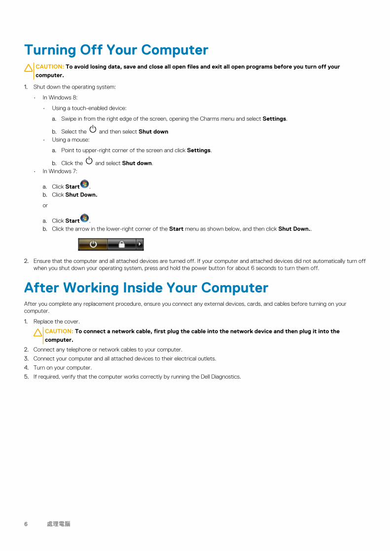
a. Click Start .b. Click the arrow in the lower-right corner of the Start menu as shown below, and then click Shut Down..
2. Ensure that the computer and all attached devices are turned off. If your computer and attached devices did not automatically turn off when you shut down your operating system, press and hold the power button for about 6 seconds to turn them off.
After Working Inside Your ComputerAfter you complete any replacement procedure, ensure you connect any external devices, cards, and cables before turning on your computer.
1. Replace the cover.
CAUTION: To connect a network cable, first plug the cable into the network device and then plug it into the
computer.
2. Connect any telephone or network cables to your computer.
3. Connect your computer and all attached devices to their electrical outlets.
4. Turn on your computer.
5. If required, verify that the computer works correctly by running the Dell Diagnostics.
6 處理電腦

卸下和安裝元件
建議的工具本文件中的程序可能需要以下工具:
• 小型一字螺絲批• 十字螺絲批• 小型塑膠拆殼棒
System Overview
Figure 1. Inside View of T3610 Computer
1. heatsink with integrated fan2. air tunnels3. front bezel4. optical drive5. air duct6. hard drive7. baffle cover8. power supply unit (PSU)9. PCI card10. intrusion switch
2
卸下和安裝元件 7
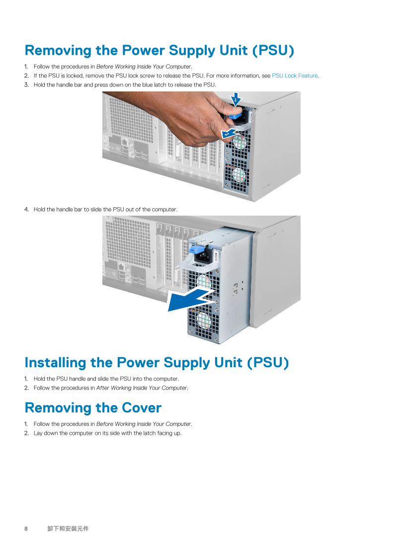
Removing the Power Supply Unit (PSU)1. Follow the procedures in Before Working Inside Your Computer.
2. If the PSU is locked, remove the PSU lock screw to release the PSU. For more information, see PSU Lock Feature.
3. Hold the handle bar and press down on the blue latch to release the PSU.
4. Hold the handle bar to slide the PSU out of the computer.
Installing the Power Supply Unit (PSU)1. Hold the PSU handle and slide the PSU into the computer.
2. Follow the procedures in After Working Inside Your Computer.
Removing the Cover1. Follow the procedures in Before Working Inside Your Computer.
2. Lay down the computer on its side with the latch facing up.
8 卸下和安裝元件
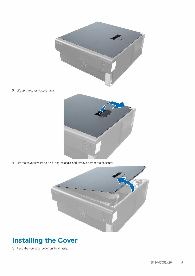
3. Lift up the cover-release latch.
4. Lift the cover upward to a 45–degree angle, and remove it from the computer.
Installing the Cover1. Place the computer cover on the chassis.
卸下和安裝元件 9
2. Press down on the computer cover until it clicks into place.
3. Follow the procedures in After Working Inside Your Computer.
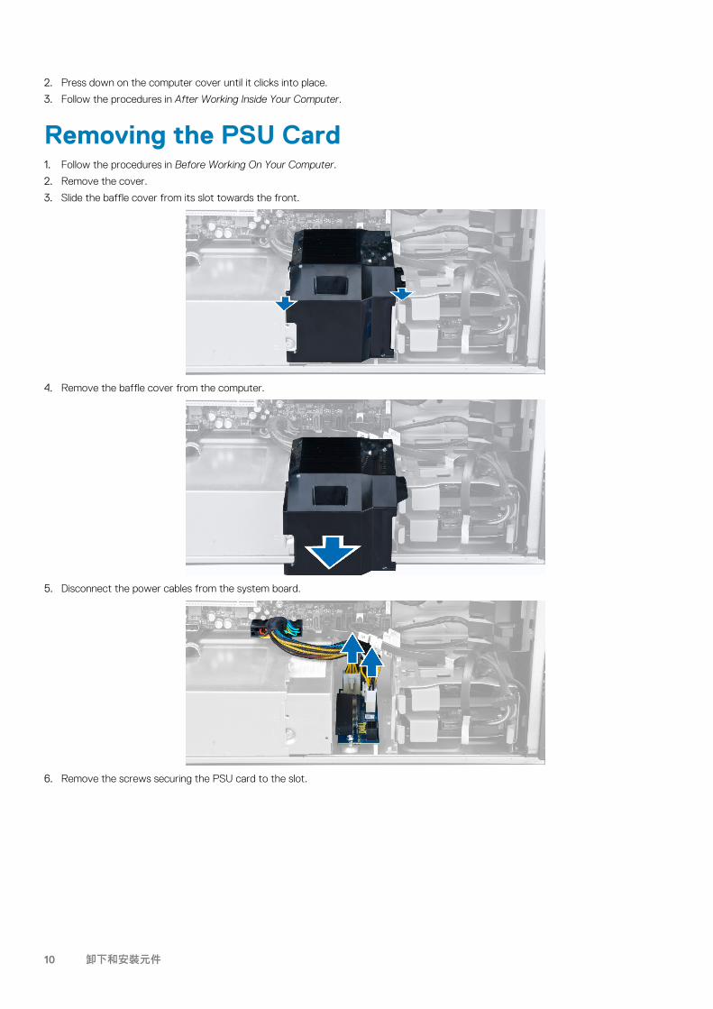
Removing the PSU Card1. Follow the procedures in Before Working On Your Computer.
2. Remove the cover.
3. Slide the baffle cover from its slot towards the front.
4. Remove the baffle cover from the computer.
5. Disconnect the power cables from the system board.
6. Remove the screws securing the PSU card to the slot.
10 卸下和安裝元件
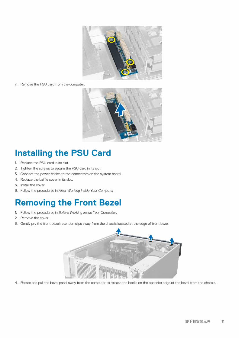
7. Remove the PSU card from the computer.
Installing the PSU Card1. Replace the PSU card in its slot.
2. Tighten the screws to secure the PSU card in its slot.
3. Connect the power cables to the connectors on the system board.
4. Replace the baffle cover in its slot.
5. Install the cover.
6. Follow the procedures in After Working Inside Your Computer.
Removing the Front Bezel1. Follow the procedures in Before Working Inside Your Computer.
2. Remove the cover.
3. Gently pry the front bezel retention clips away from the chassis located at the edge of front bezel.
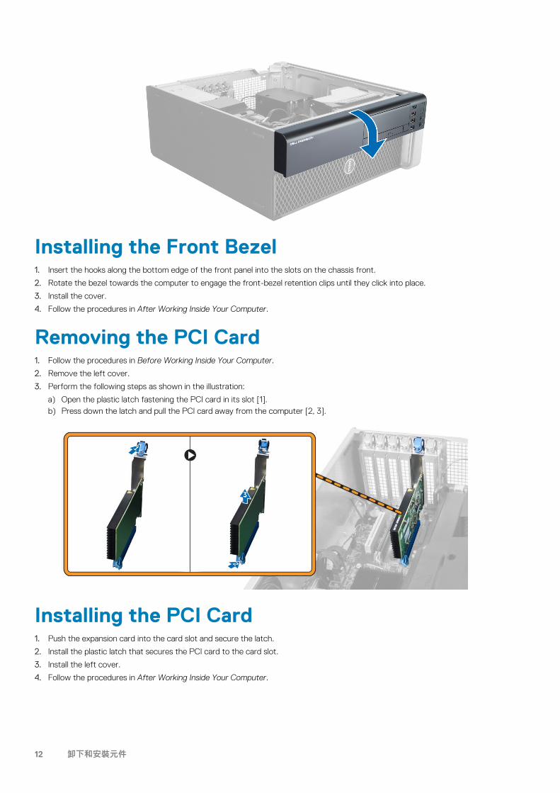
4. Rotate and pull the bezel panel away from the computer to release the hooks on the opposite edge of the bezel from the chassis.
卸下和安裝元件 11
Installing the Front Bezel1. Insert the hooks along the bottom edge of the front panel into the slots on the chassis front.
2. Rotate the bezel towards the computer to engage the front-bezel retention clips until they click into place.
3. Install the cover.
4. Follow the procedures in After Working Inside Your Computer.
Removing the PCI Card1. Follow the procedures in Before Working Inside Your Computer.
2. Remove the left cover.
3. Perform the following steps as shown in the illustration:
a) Open the plastic latch fastening the PCI card in its slot [1].b) Press down the latch and pull the PCI card away from the computer [2, 3].
Installing the PCI Card1. Push the expansion card into the card slot and secure the latch.
2. Install the plastic latch that secures the PCI card to the card slot.
3. Install the left cover.
4. Follow the procedures in After Working Inside Your Computer.
12 卸下和安裝元件
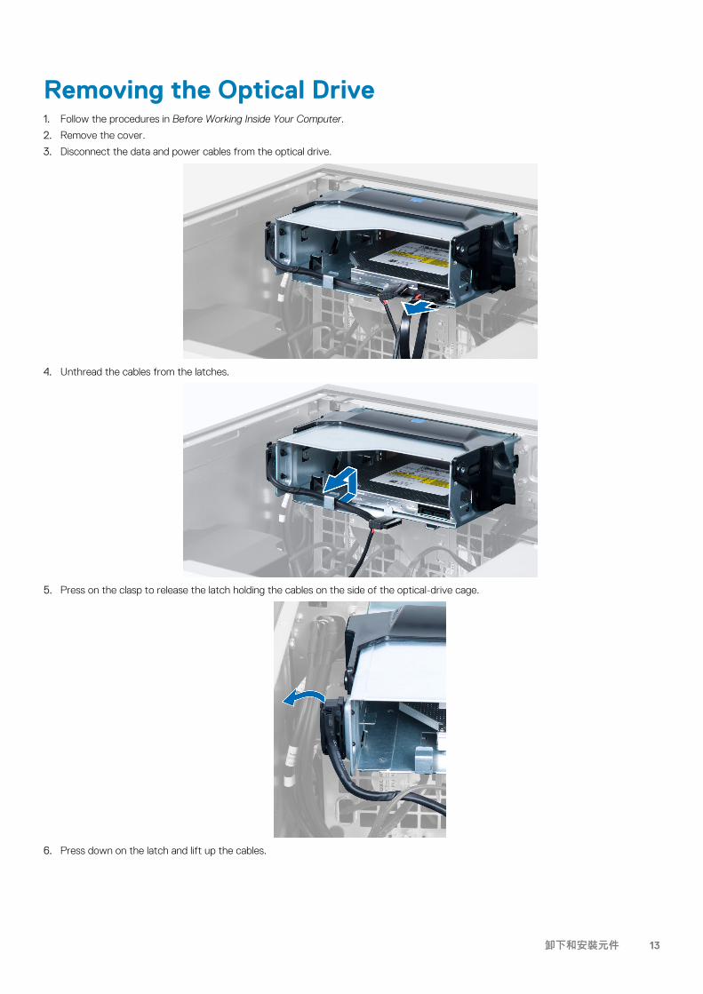
Removing the Optical Drive1. Follow the procedures in Before Working Inside Your Computer.
2. Remove the cover.
3. Disconnect the data and power cables from the optical drive.
4. Unthread the cables from the latches.
5. Press on the clasp to release the latch holding the cables on the side of the optical-drive cage.
6. Press down on the latch and lift up the cables.
卸下和安裝元件 13

7. Lift up the release latch on top of the optical-drive cage.
8. Holding the release latch, slide the optical-drive cage from the optical-drive compartment.
Installing the Optical Drive1. Lift the release latch, and slide the optical-drive cage inside the compartment.
2. Press on the clasp to release the latch and thread the cables into the holder.
3. Connect the power cable to the back of the optical drive.
4. Connect the data cable to the back of the optical drive.
5. Install the cover.
6. Follow the procedures in After Working Inside Your Computer.
14 卸下和安裝元件
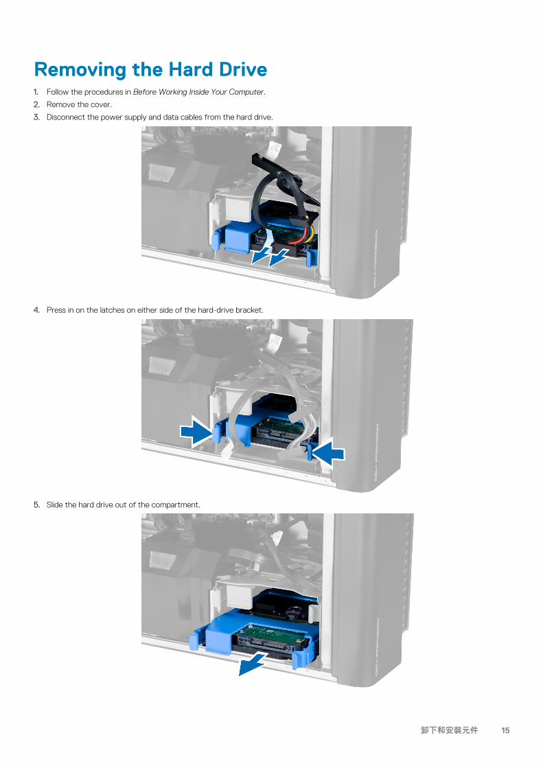
Removing the Hard Drive1. Follow the procedures in Before Working Inside Your Computer.
2. Remove the cover.
3. Disconnect the power supply and data cables from the hard drive.
4. Press in on the latches on either side of the hard-drive bracket.
5. Slide the hard drive out of the compartment.
卸下和安裝元件 15
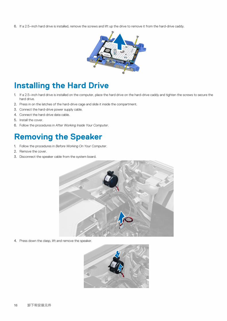
6. If a 2.5–inch hard drive is installed, remove the screws and lift up the drive to remove it from the hard-drive caddy.
Installing the Hard Drive1. If a 2.5–inch hard drive is installed on the computer, place the hard drive on the hard-drive caddy and tighten the screws to secure the
hard drive.
2. Press in on the latches of the hard-drive cage and slide it inside the compartment.
3. Connect the hard-drive power supply cable.
4. Connect the hard-drive data cable.
5. Install the cover.
6. Follow the procedures in After Working Inside Your Computer.
Removing the Speaker1. Follow the procedures in Before Working On Your Computer.
2. Remove the cover.
3. Disconnect the speaker cable from the system board.
4. Press down the clasp, lift and remove the speaker.
16 卸下和安裝元件
Installing the Speaker1. Replace the speaker and fix the clasp.
2. Connect the speaker cable to the system board.
3. Install the cover.
4. Follow the procedures in After Working Inside Your Computer.
Installing the Thermal SensorNOTE: The Thermal Sensor is an optional component and your computer may not ship with it.
1. Replace the thermal sensor in its slot and tighten the latch securing it to the computer.
2. Install the cover.
3. Follow the procedures in After Working Inside Your Computer.
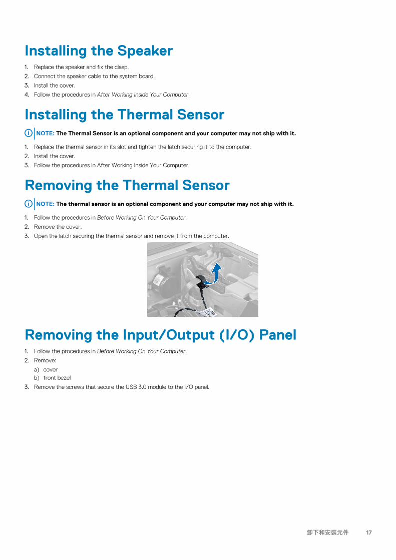
Removing the Thermal SensorNOTE: The thermal sensor is an optional component and your computer may not ship with it.
1. Follow the procedures in Before Working On Your Computer.
2. Remove the cover.
3. Open the latch securing the thermal sensor and remove it from the computer.
Removing the Input/Output (I/O) Panel1. Follow the procedures in Before Working On Your Computer.
2. Remove:
a) coverb) front bezel
3. Remove the screws that secure the USB 3.0 module to the I/O panel.
卸下和安裝元件 17

4. Remove the USB 3.0 module from the chassis.
5. Disconnect the cables to release the I/O panel.
6. Remove the screws which secure the I/O panel to the chassis.
18 卸下和安裝元件
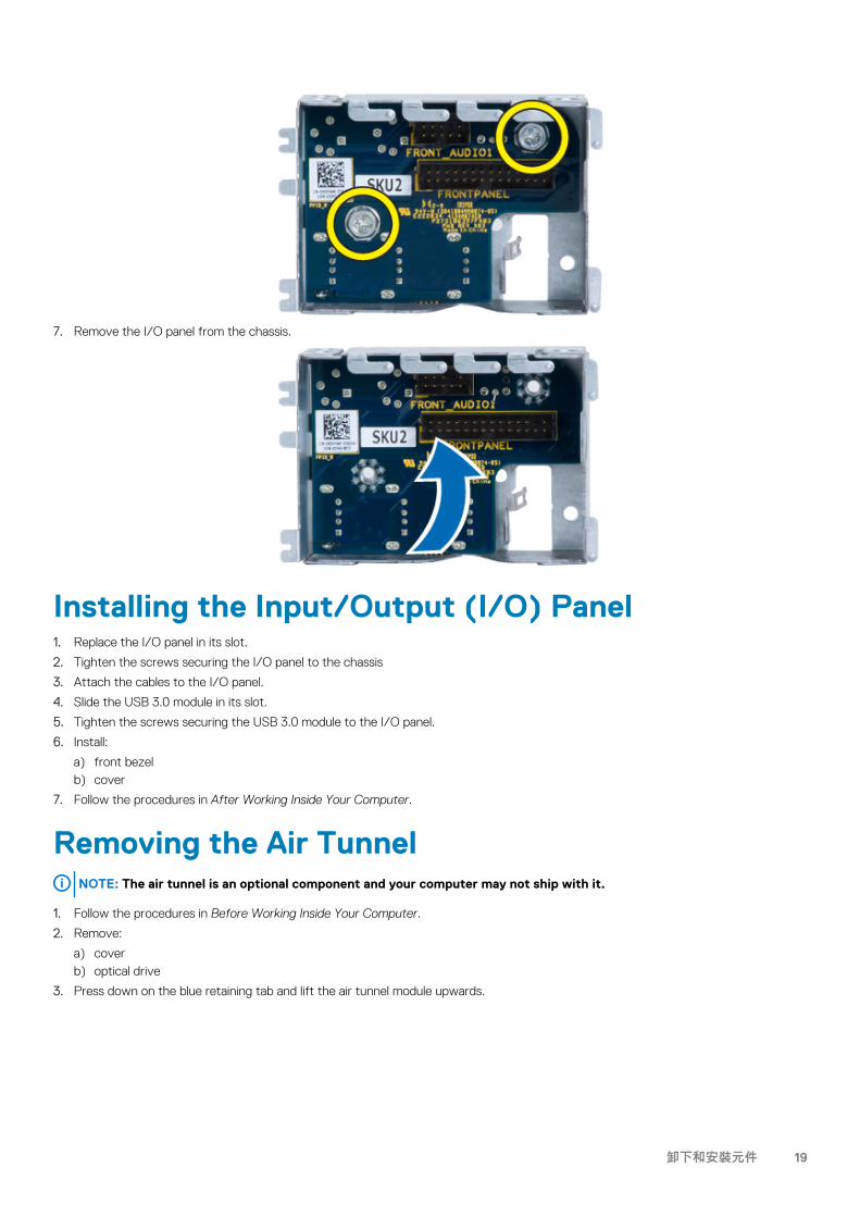
7. Remove the I/O panel from the chassis.
Installing the Input/Output (I/O) Panel1. Replace the I/O panel in its slot.
2. Tighten the screws securing the I/O panel to the chassis
3. Attach the cables to the I/O panel.
4. Slide the USB 3.0 module in its slot.
5. Tighten the screws securing the USB 3.0 module to the I/O panel.
6. Install:
a) front bezelb) cover
7. Follow the procedures in After Working Inside Your Computer.
Removing the Air TunnelNOTE: The air tunnel is an optional component and your computer may not ship with it.
1. Follow the procedures in Before Working Inside Your Computer.
2. Remove:
a) coverb) optical drive
3. Press down on the blue retaining tab and lift the air tunnel module upwards.
卸下和安裝元件 19

4. Repeat Step 3 to remove the second air tunnel module from the computer.
Installing the Air TunnelNOTE: The air tunnel is an optional component and your computer may not ship with it.
1. Install the air tunnel base inside the computer chassis.
2. Mount the air tunnel module on the base and press downwards until it clicks into place.
3. Install:
a) optical driveb) cover
4. Follow the procedures in After Working Inside Your Computer.
Removing the Memory1. Follow the procedures in Before Working Inside Your Computer.
2. Remove:
a) coverb) air tunnel (if available)
3. Press down on the memory-securing clips on each side of the memory module, and lift the memory module upwards to remove it from the computer.
Installing the Memory1. Insert the memory module into the memory socket.
2. Press down on the memory module until the securing clips secure the memory in place.
3. Install:
a) air tunnel (if available)b) cover
20 卸下和安裝元件
4. Follow the procedures in After Working Inside Your Computer.
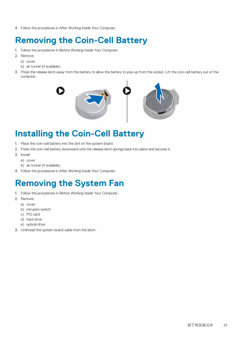
Removing the Coin-Cell Battery1. Follow the procedures in Before Working Inside Your Computer.
2. Remove:
a) coverb) air tunnel (if available)
3. Press the release latch away from the battery to allow the battery to pop-up from the socket. Lift the coin-cell battery out of the computer.
Installing the Coin-Cell Battery1. Place the coin-cell battery into the slot on the system board.
2. Press the coin-cell battery downward until the release latch springs back into place and secures it.
3. Install:
a) coverb) air tunnel (if available)
4. Follow the procedures in After Working Inside Your Computer.
Removing the System Fan1. Follow the procedures in Before Working Inside Your Computer.
2. Remove:
a) coverb) intrusion switchc) PCI cardd) hard drivee) optical drive
3. Unthread the system-board cable from the latch.
卸下和安裝元件 21

4. Remove the screw that secures metal plate to the system fan.
5. Press the latches on either side of the metal plate to release it.
6. Lift the metal plate out of the chassis.
22 卸下和安裝元件
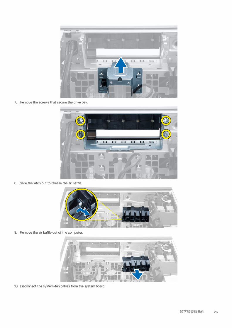
7. Remove the screws that secure the drive bay.
8. Slide the latch out to release the air baffle.
9. Remove the air baffle out of the computer.
10. Disconnect the system-fan cables from the system board.
卸下和安裝元件 23
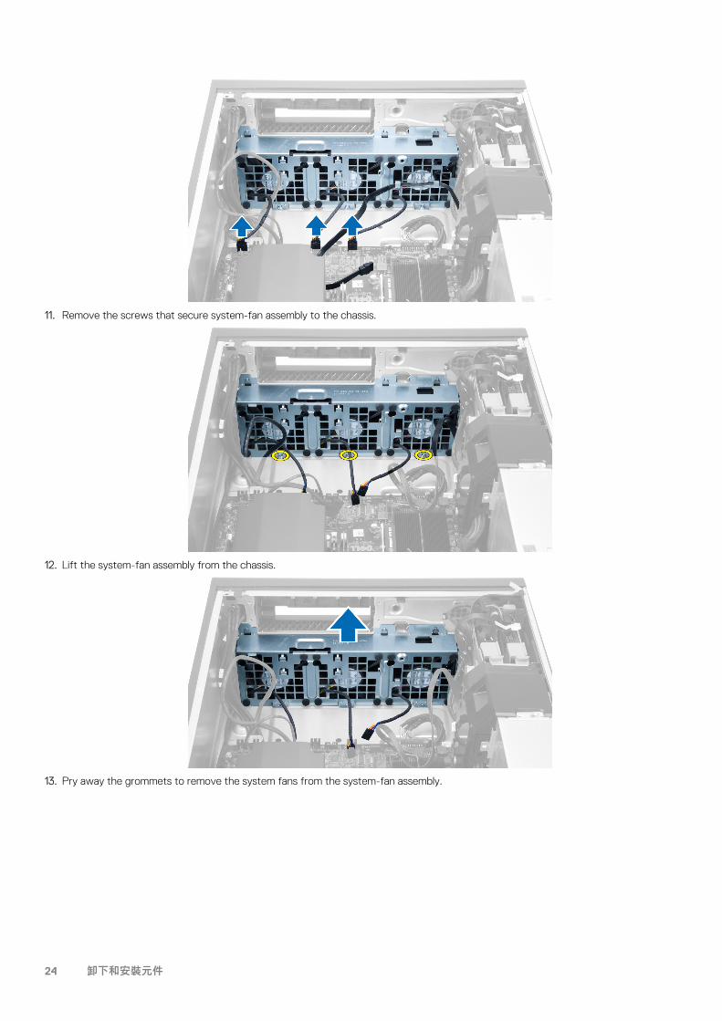
11. Remove the screws that secure system-fan assembly to the chassis.
12. Lift the system-fan assembly from the chassis.
13. Pry away the grommets to remove the system fans from the system-fan assembly.
24 卸下和安裝元件
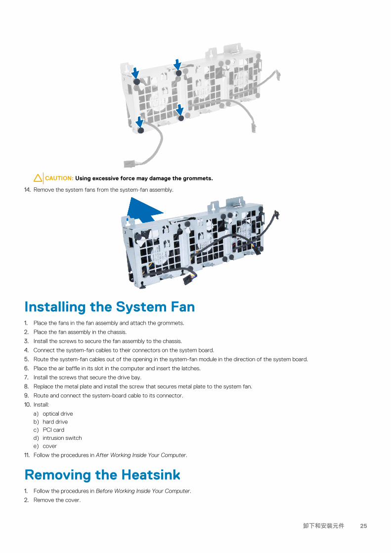
CAUTION: Using excessive force may damage the grommets.
14. Remove the system fans from the system-fan assembly.
Installing the System Fan1. Place the fans in the fan assembly and attach the grommets.
2. Place the fan assembly in the chassis.
3. Install the screws to secure the fan assembly to the chassis.
4. Connect the system-fan cables to their connectors on the system board.
5. Route the system-fan cables out of the opening in the system-fan module in the direction of the system board.
6. Place the air baffle in its slot in the computer and insert the latches.
7. Install the screws that secure the drive bay.
8. Replace the metal plate and install the screw that secures metal plate to the system fan.
9. Route and connect the system-board cable to its connector.
10. Install:
a) optical driveb) hard drivec) PCI cardd) intrusion switche) cover
11. Follow the procedures in After Working Inside Your Computer.
Removing the Heatsink1. Follow the procedures in Before Working Inside Your Computer.
2. Remove the cover.
卸下和安裝元件 25
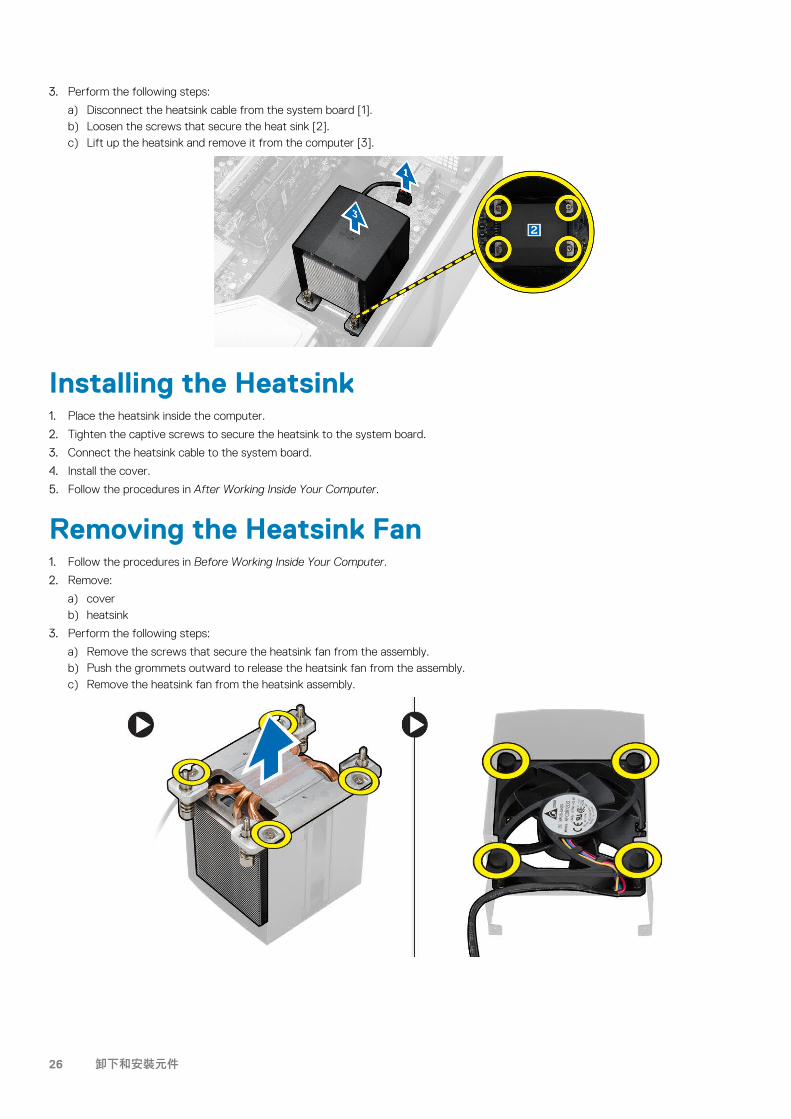
3. Perform the following steps:
a) Disconnect the heatsink cable from the system board [1].b) Loosen the screws that secure the heat sink [2].c) Lift up the heatsink and remove it from the computer [3].
Installing the Heatsink1. Place the heatsink inside the computer.
2. Tighten the captive screws to secure the heatsink to the system board.
3. Connect the heatsink cable to the system board.
4. Install the cover.
5. Follow the procedures in After Working Inside Your Computer.
Removing the Heatsink Fan1. Follow the procedures in Before Working Inside Your Computer.
2. Remove:
a) coverb) heatsink
3. Perform the following steps:
a) Remove the screws that secure the heatsink fan from the assembly.b) Push the grommets outward to release the heatsink fan from the assembly.c) Remove the heatsink fan from the heatsink assembly.
26 卸下和安裝元件

Installing the Heatsink Fan1. Slide the heatsink fan into heatsink assembly.
2. Plug in the grommets to secure the heatsink fan to the heatsink assembly.
3. Install:
a) heatsinkb) cover
4. Follow the procedures in After Working Inside Your Computer.
Removing the Processor1. Follow the procedures in Before Working Inside Your Computer.
2. Remove:
a) coverb) air tunnel (if available)c) heatsink
3. To remove the processor:
NOTE: The processor cover is secured by two levers. They have icons that indicate which lever needs to be opened
first and which lever closes first.
a) Press down on the first lever holding the processor cover in place and release it sideways from its retention hook.b) Repeat step 'a' to release the second lever from its retention hook.c) Lift up and remove the processor cover.d) Lift the processor to remove it from the socket and place it in antistatic package.
4. Repeat the above steps to remove the second processor (if available) from the computer.
To verify if your computer has dual processor slots, see the System Board Components.
Installing the Processor1. Place the processor in its socket.
2. Replace the processor cover.
卸下和安裝元件 27
NOTE: The processor cover is secured by two levers. They have icons that indicate which lever needs to be opened
first and which lever closes first.
3. Slide the first lever sideways into the retention hook to secure the processor.
4. Repeat step '3' to slide the second lever into the retention hook.
5. Install:
a) heatsinkb) air tunnel (if available)c) cover
6. Follow the procedures in After Working Inside Your Computer.
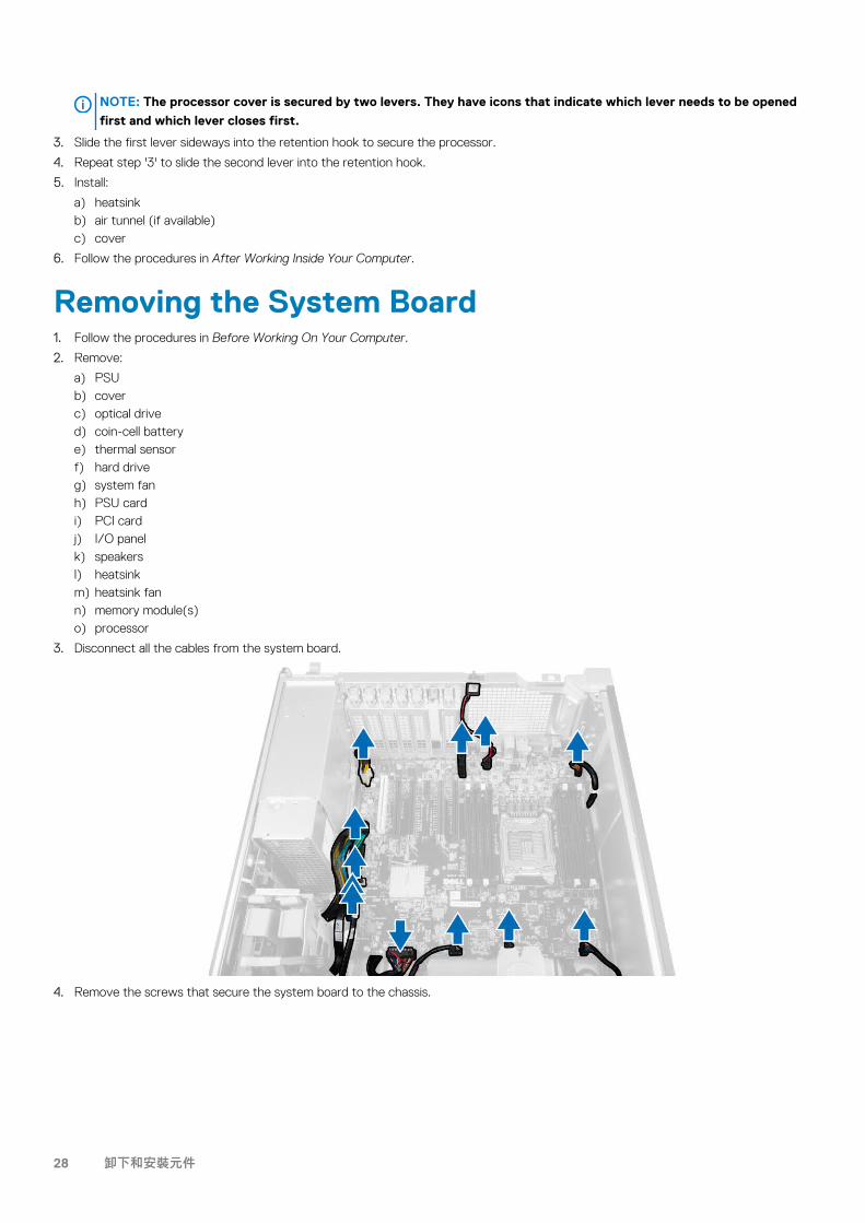
Removing the System Board1. Follow the procedures in Before Working On Your Computer.
2. Remove:
a) PSUb) coverc) optical drived) coin-cell batterye) thermal sensorf) hard driveg) system fanh) PSU cardi) PCI cardj) I/O panelk) speakersl) heatsinkm) heatsink fann) memory module(s)o) processor
3. Disconnect all the cables from the system board.
4. Remove the screws that secure the system board to the chassis.
28 卸下和安裝元件
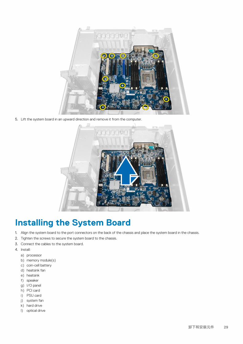
5. Lift the system board in an upward direction and remove it from the computer.
Installing the System Board1. Align the system board to the port connectors on the back of the chassis and place the system board in the chassis.
2. Tighten the screws to secure the system board to the chassis.
3. Connect the cables to the system board.
4. Install:
a) processorb) memory module(s)c) coin-cell batteryd) heatsink fane) heatsinkf) speakerg) I/O panelh) PCI cardi) PSU cardj) system fank) hard drivel) optical drive
卸下和安裝元件 29
m) thermal sensorn) covero) power supply unit (PSU)
5. Follow the procedures in After Working Inside Your Computer.
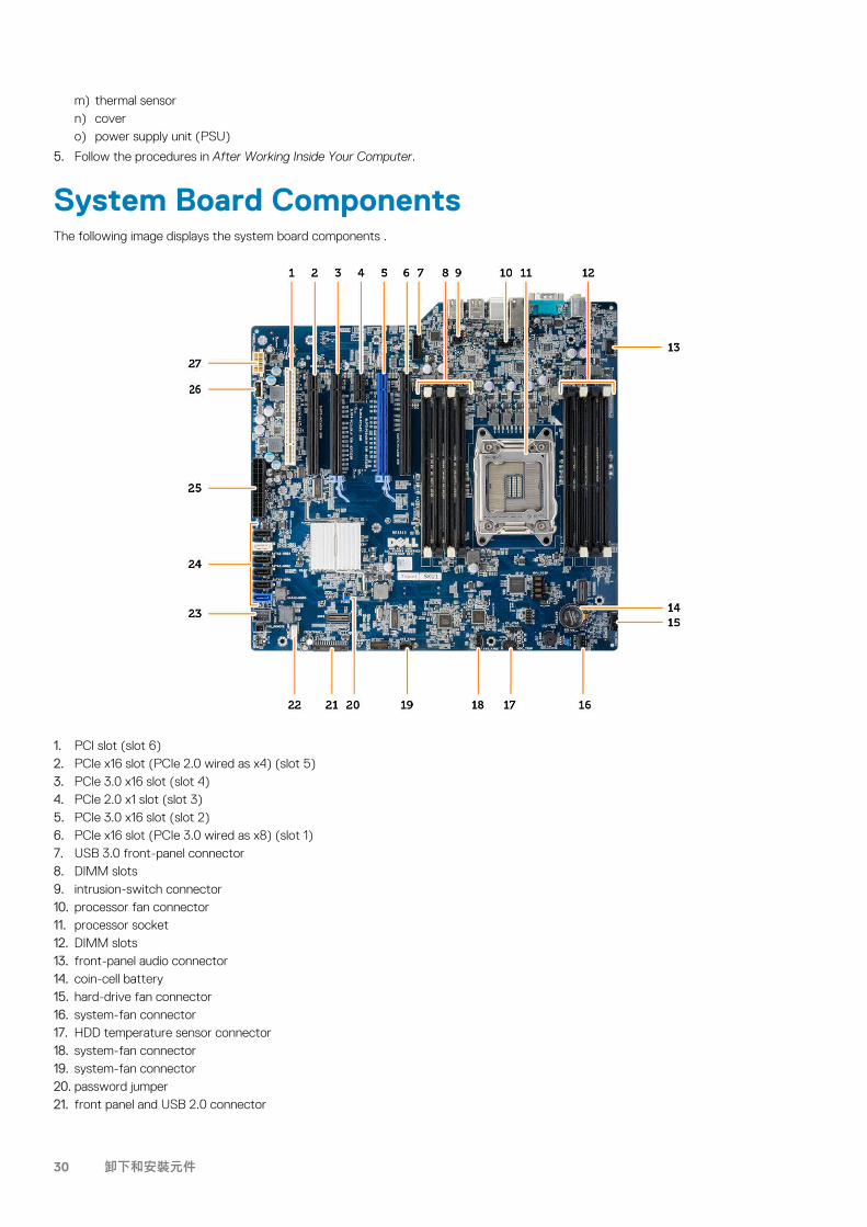
System Board ComponentsThe following image displays the system board components .
1. PCI slot (slot 6)2. PCIe x16 slot (PCIe 2.0 wired as x4) (slot 5)3. PCIe 3.0 x16 slot (slot 4)4. PCIe 2.0 x1 slot (slot 3)5. PCIe 3.0 x16 slot (slot 2)6. PCIe x16 slot (PCIe 3.0 wired as x8) (slot 1)7. USB 3.0 front-panel connector8. DIMM slots9. intrusion-switch connector10. processor fan connector11. processor socket12. DIMM slots13. front-panel audio connector14. coin-cell battery15. hard-drive fan connector16. system-fan connector17. HDD temperature sensor connector18. system-fan connector19. system-fan connector20. password jumper21. front panel and USB 2.0 connector
30 卸下和安裝元件
22. internal speaker connector23. internal USB 2.0 connector for flexbay24. SATA Connectors (HDD0-HDD3 & SATA0-1)25. 24-pin system power connector26. internal USB 2.0 Connector27. 8–pin CPU power connector
卸下和安裝元件 31
Additional Information
Memory Module GuidelinesTo ensure optimal performance of your computer, observe the following general guidelines when configuring your system memory:
• Memory modules of different sizes can be mixed (for example, 2 GB and 4 GB). But, all populated channels must have identical configurations.
• Memory modules must be installed beginning with the first socket.NOTE: The memory sockets in your computer may be labeled differently depending on the hardware configuration.
For example, A1, A2 or 1,2,3.
• If the quad-rank memory modules are mixed with single or dual-rank modules, the quad-rank modules must be installed in the sockets with the white release levers.
• If memory modules with different speeds are installed, they operate at the speed of the slowest installed memory modules.
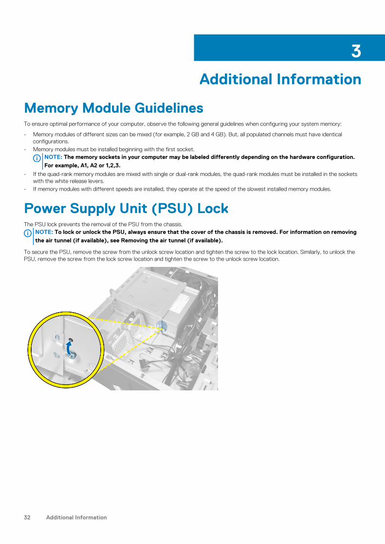
Power Supply Unit (PSU) LockThe PSU lock prevents the removal of the PSU from the chassis.
NOTE: To lock or unlock the PSU, always ensure that the cover of the chassis is removed. For information on removing
the air tunnel (if available), see Removing the air tunnel (if available).
To secure the PSU, remove the screw from the unlock screw location and tighten the screw to the lock location. Similarly, to unlock the PSU, remove the screw from the lock screw location and tighten the screw to the unlock screw location.
3
32 Additional Information
System SetupSystem Setup enables you to manage your computer hardware and specify BIOS‐level options. From the System Setup, you can:
• Change the NVRAM settings after you add or remove hardware• View the system hardware configuration• Enable or disable integrated devices• Set performance and power management thresholds• Manage your computer security
Topics:
• Boot Sequence (開機順序)• Navigation Keys• System Setup Options• Updating the BIOS • System and Setup Password
Boot Sequence (開機順序)Boot Sequence (開機順序) 可讓您略過系統設定定義的啟動裝置順序,並直接開機至特定裝置 (例如:光碟機或硬碟)。開機自我測試 (POST) 期間,當螢幕上出現 Dell 標誌時,您可以:
• 按下 <F2> 鍵存取系統設定• 按下 <F12> 鍵顯示單次開機功能表
單次開機功能表會顯示可用的開機裝置,包括診斷選項。可用的開機功能表選項有:
• Removable Drive (卸除式磁碟機) (如有)• STXXXX Drive (STXXXX 磁碟機)
備註: XXX 代表 SATA 磁碟機編號。
• Optical Drive (光碟機)• Diagnostics (診斷)
備註: 選擇 Diagnostics (診斷) 將會顯示 ePSA diagnostics (ePSA 診斷) 畫面。
開機順序畫面也會顯示選項,讓您存取 System Setup (系統設定) 畫面。
Navigation KeysThe following table displays the system setup navigation keys.
NOTE: For most of the system setup options, changes that you make are recorded but do not take effect until you
restart the system.
Table 1. Navigation Keys
Keys Navigation
Up arrow Moves to the previous field.
Down arrow Moves to the next field.
<Enter> Allows you to select a value in the selected field (if applicable) or follow the link in the field.
Spacebar Expands or collapses a drop‐down list, if applicable.
<Tab> Moves to the next focus area.
NOTE: For the standard graphics browser only.
4
System Setup 33
Keys Navigation
<Esc> Moves to the previous page till you view the main screen. Pressing <Esc> in the main screen displays a message that prompts you to save any unsaved changes and restarts the system.
<F1> Displays the System Setup help file.
System Setup OptionsNOTE: Depending on your computer and its installed devices, the items listed in this section may or may not appear.
Table 2. General
Option Description
System Board This section lists the primary hardware features of your computer.
• System Information• Memory Configuration• PCI Information• Processor Information• Device Information
Boot Sequence Allows you to change the order in which the computer attempts to find an operating system.
• Diskette Drive• Internal HDD• USB Storage Device• CD/DVD/CD-RW Drive• Onboard NIC• SATA
Boot List Option Allows you to change the boot list option.
• Legacy• UEFI
Advanced Boot Options Allows you to Enable Legacy Option ROMs
• Disabled• Enabled (Default)
Date/Time Allows you to set the date and time. The changes to the system date and time takes effect immediately.
Table 3. System Configuration
Option Description
Integrated NIC Allows you to configure the integrated network controller. The options are:
• DisabledNOTE: You can use the Disabled option, only if Active Management Technology (AMT) option is disabled.
• Enable UEFI Network Stack• Enabled (Default)• Enabled w/PXE
Integrated NIC 2 Allows you to control on-board LAN controller. The options are:
• Enable (Default)• Enable w/PXE
NOTE: This feature is supported only on T7610
34 System Setup

Option Description
Serial Port Identifies and defines the serial port settings. You can set the serial port to:
• Disabled• COM1 (Default)• COM2• COM3• COM4
NOTE: The operating system may allocate resources even if the setting is disabled.
SATA Operation
T3610 and T5610 Allows you to configure the internal SATA hard-drive controller. The options are:
• Disabled• ATA• AHCI (Default)• RAID On
NOTE: SATA is configured to support RAID mode. No SATA operation support in T7610.
Drives
T3610 and T5610 Allows you to configure the SATA drives on board. The options are:
• SATA3–HDD0• SATA2–HDD2• SATA2–ODD0• SATA3–HDD1• SATA2–HDD3• SATA2–ODD1
Default Setting: All drives are enabled.
NOTE: If the hard drives are connected to a RAID controller card, the hard drives will display {none} in all the fields. The hard drives can be seen in the RAID controller card BIOS.
• T7610 • SATA2–ODD0• SATA2–ODD1
Default Setting: All drives are enabled.
NOTE: If the hard drives are connected to a RAID controller card, the hard drives will display {none} in all the fields. The hard drives can be seen in the RAID controller card BIOS.
SMART Reporting This field controls if the hard drive errors for the integrated drives are reported during system startup. This technology is part of the SMART (Self Monitoring Analysis and Reporting Technology) specification.
• Enable SMART Reporting - This option is disabled by default.
USB Configuration Allows you to enable or disable the internal USB configuration. The options are:
• Enable Boot Support• Front USB Ports• Back Quad USB Ports• Enable internal USB ports• USB3 Ports
PCI Bus Configuration Allows you to configure the PCI buses. The options are:
• 256 PCI Buses (Default)• 128 PCI Buses• 64 PCI Buses
System Setup 35
Option Description
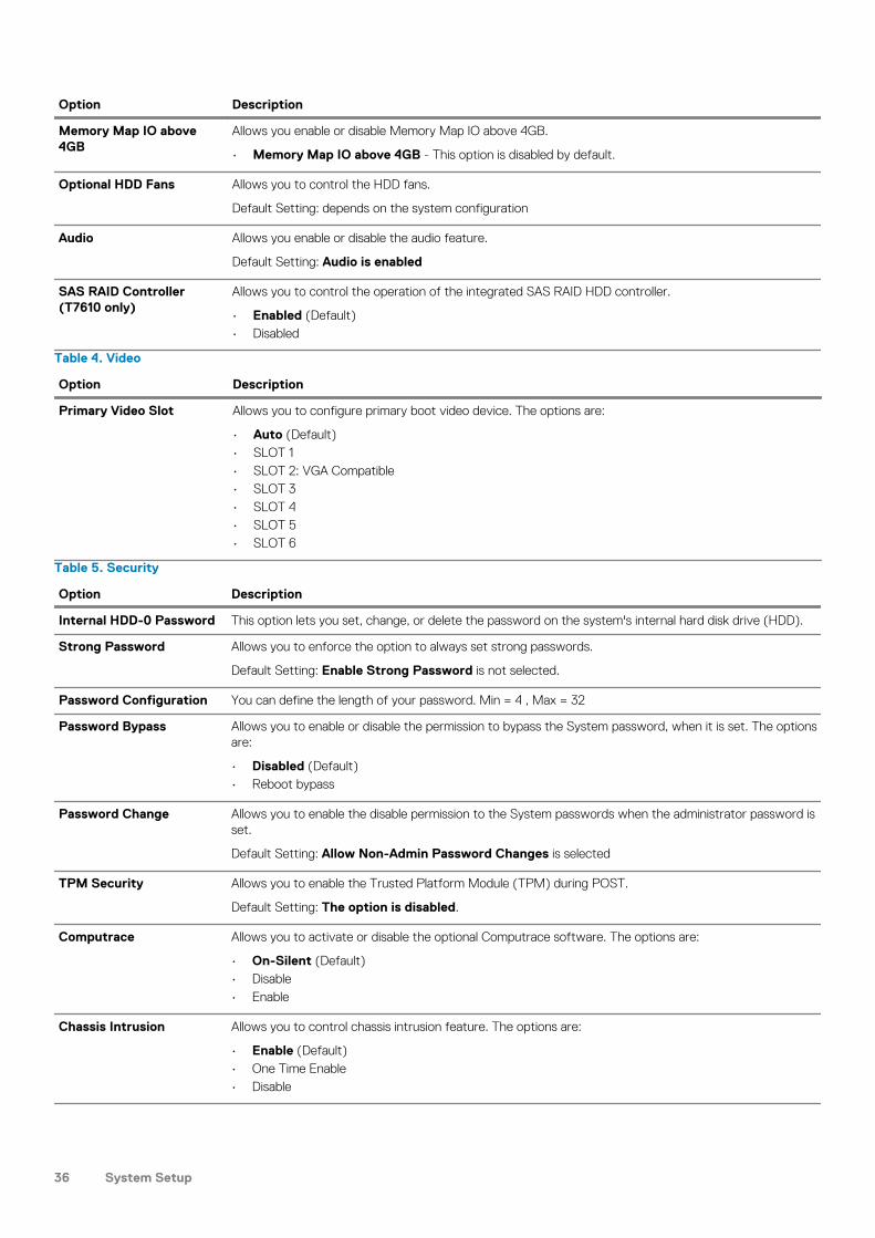
Memory Map IO above 4GB
Allows you enable or disable Memory Map IO above 4GB.
• Memory Map IO above 4GB - This option is disabled by default.
Optional HDD Fans Allows you to control the HDD fans.
Default Setting: depends on the system configuration
Audio Allows you enable or disable the audio feature.
Default Setting: Audio is enabled
SAS RAID Controller (T7610 only)
Allows you to control the operation of the integrated SAS RAID HDD controller.
• Enabled (Default)• Disabled
Table 4. Video
Option Description
Primary Video Slot Allows you to configure primary boot video device. The options are:
• Auto (Default)• SLOT 1• SLOT 2: VGA Compatible• SLOT 3• SLOT 4• SLOT 5• SLOT 6
Table 5. Security
Option Description
Internal HDD-0 Password This option lets you set, change, or delete the password on the system's internal hard disk drive (HDD).
Strong Password Allows you to enforce the option to always set strong passwords.
Default Setting: Enable Strong Password is not selected.
Password Configuration You can define the length of your password. Min = 4 , Max = 32
Password Bypass Allows you to enable or disable the permission to bypass the System password, when it is set. The options are:
• Disabled (Default)• Reboot bypass
Password Change Allows you to enable the disable permission to the System passwords when the administrator password is set.
Default Setting: Allow Non-Admin Password Changes is selected
TPM Security Allows you to enable the Trusted Platform Module (TPM) during POST.
Default Setting: The option is disabled.
Computrace Allows you to activate or disable the optional Computrace software. The options are:
• On-Silent (Default)• Disable• Enable
Chassis Intrusion Allows you to control chassis intrusion feature. The options are:
• Enable (Default)• One Time Enable• Disable
36 System Setup

Option Description
CPU XD Support Allows you to enable the Execute Disable mode of the processor.
Default Setting: Enable CPU XD Support
OROM Keyboard Access Allows you to determine whether users are able to enter Option ROM Configuration screens via hotkeys during boot. The options are:
• Enable (Default)• One Time Enable• Disable
Admin Setup Lockout Allows you to prevent users from entering Setup when an administrator password is set.
Default Setting: Disabled
Table 6. Secure Boot
Option Description
Secure Boot Enable Allows you to enable or disable the Secure Boot Feature. The options are:
• Disabled (Default)• Enabled
Expert Key Management Allows you to enable or disable Custom Mode Key Management.
• Disabled (Default)
Table 7. Performance
Option Description
Multi Core Support This field specifies whether the processor will have one or all cores enabled. The performance of some applications will improve with the additional cores. This option is enabled by default. Allows you to enable or disable multi-core support for the processor. The options are:
• All (Default)• 1• 2• 4• 5• 6• 7• 8• 9
NOTE:
• The options displayed could be different depending on the installed processor(s).
• The options depend on the number of cores supported by the installed processor (All, 1, 2, N-1 for N-Core Processors)
Intel SpeedStep Allows you to enable or disable the Intel SpeedStep feature.
Default Setting: Enable Intel SpeedStep
C States Control Allows you to enable or disable the additional processor sleep states.
Default Setting:Enabled
Intel TurboBoost Allows you to enable or disable the Intel TurboBoost mode of the processor.
Default Setting: Enable Intel TurboBoost
Hyper-Thread Control Allows you to enable or disable the HyperThreading in the processor.
Default Setting: Enabled
Cache Prefetch Default Setting: Enable Hardware Prefetch and Adjacent Cache Line Prefetch
System Setup 37
Option Description
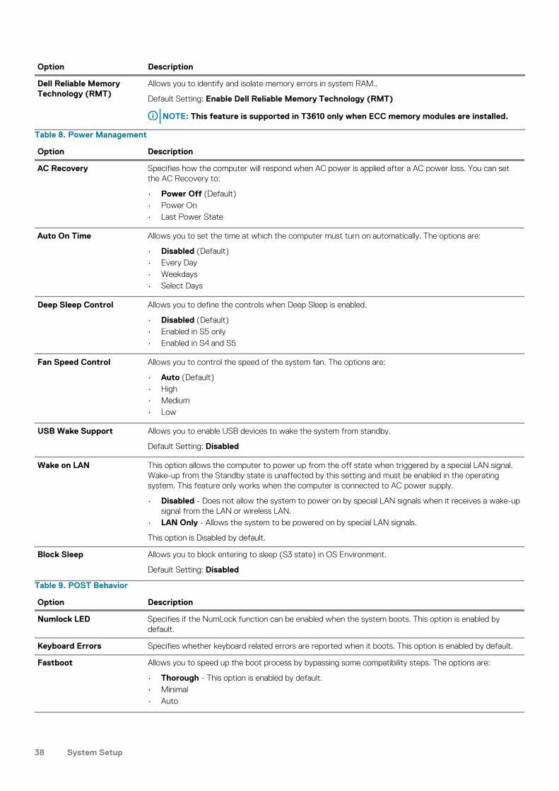
Dell Reliable Memory Technology (RMT)
Allows you to identify and isolate memory errors in system RAM..
Default Setting: Enable Dell Reliable Memory Technology (RMT)
NOTE: This feature is supported in T3610 only when ECC memory modules are installed.
Table 8. Power Management
Option Description
AC Recovery Specifies how the computer will respond when AC power is applied after a AC power loss. You can set the AC Recovery to:
• Power Off (Default)• Power On• Last Power State
Auto On Time Allows you to set the time at which the computer must turn on automatically. The options are:
• Disabled (Default)• Every Day• Weekdays• Select Days
Deep Sleep Control Allows you to define the controls when Deep Sleep is enabled.
• Disabled (Default)• Enabled in S5 only• Enabled in S4 and S5
Fan Speed Control Allows you to control the speed of the system fan. The options are:
• Auto (Default)• High• Medium• Low
USB Wake Support Allows you to enable USB devices to wake the system from standby.
Default Setting: Disabled
Wake on LAN This option allows the computer to power up from the off state when triggered by a special LAN signal. Wake-up from the Standby state is unaffected by this setting and must be enabled in the operating system. This feature only works when the computer is connected to AC power supply.
• Disabled - Does not allow the system to power on by special LAN signals when it receives a wake-up signal from the LAN or wireless LAN.
• LAN Only - Allows the system to be powered on by special LAN signals.
This option is Disabled by default.
Block Sleep Allows you to block entering to sleep (S3 state) in OS Environment.
Default Setting: Disabled
Table 9. POST Behavior
Option Description
Numlock LED Specifies if the NumLock function can be enabled when the system boots. This option is enabled by default.
Keyboard Errors Specifies whether keyboard related errors are reported when it boots. This option is enabled by default.
Fastboot Allows you to speed up the boot process by bypassing some compatibility steps. The options are:
• Thorough - This option is enabled by default.• Minimal• Auto
38 System Setup

Table 10. Virtualization Support
Option Description
Virtualization This option specifies whether a Virtual Machine Monitor (VMM) can utilize the additional hardware capabilities provided by Intel Virtualization technology.
• Enable Intel Virtualization Technology - This option is enabled by default.
VT for Direct I/O Enables or disables the Virtual Machine Monitor (VMM) from utilizing the additional hardware capabilities provided by Intel Virtualization technology for direct I/O.
• Enable Intel Virtualization Technology for Direct I/O - This option is enabled by default.
Trusted Execution Allows you to specify whether a Measured Virtual Machine Monitor (MVMM) can utilize the additional hardware capabilities provided by Intel Trusted Execution Program.
• Trusted Execution - This option is disabled by default.
Table 11. Maintenance
Option Description
Service Tag Displays the service tag of your computer.
Asset Tag Allows you to create a system asset tag if an asset tag is not already set. This option is not set by default.
SERR Messages Controls the SERR message mechanism. This option is not set by default. Some graphics cards require that the SERR message mechanism be disabled.
Table 12. System Logs
Option Description
BIOS events Displays the system event log and allows you to clear the log.
• Clear Log
Updating the BIOSIt is recommended to update your BIOS (system setup), on replacing the system board or if an update is available. For laptops, ensure that your computer battery is fully charged and connected to a power outlet
1. Restart the computer.
2. Go to dell.com/support.
3. If you have your computer's Service Tag or Express Service Code:
NOTE: To locate the Service Tag, click Where is my Service Tag?
NOTE: If you cannot find your Service Tag, click Detect Service Tag. Proceed with the instructions on screen.
4. Enter the Service Tag or Express Service Code and click Submit.
5. If you are unable to locate or find the Service Tag, click the Product Category of your computer.
6. Choose the Product Type from the list.
7. Select your computer model and the Product Support page of your computer appears.
8. Click Drivers & Downloads.
9. On the Drivers and Downloads screen, under the Operating System drop-down list, select BIOS.
10. Identify the latest BIOS file and click Download File.
11. Select your preferred download method in the Please select your download method below window; click Download File.The File Download window appears.
12. Click Save to save the file on your computer.
13. Click Run to install the updated BIOS settings on your computer.
Follow the instructions on the screen.
System Setup 39
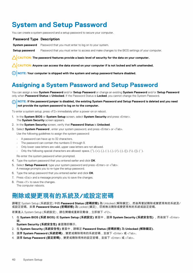
System and Setup PasswordYou can create a system password and a setup password to secure your computer.
Password Type Description
System password Password that you must enter to log on to your system.
Setup password Password that you must enter to access and make changes to the BIOS settings of your computer.
CAUTION: The password features provide a basic level of security for the data on your computer.
CAUTION: Anyone can access the data stored on your computer if is not locked and left unattended.
NOTE: Your computer is shipped with the system and setup password feature disabled.
Assigning a System Password and Setup PasswordYou can assign a new System Password and/or Setup Password or change an existing System Password and/or Setup Password only when Password Status is Unlocked. If the Password Status is Locked, you cannot change the System Password.
NOTE: If the password jumper is disabled, the existing System Password and Setup Password is deleted and you need
not provide the system password to log on to the computer.
To enter a system setup, press <F2> immediately after a power-on or reboot.
1. In the System BIOS or System Setup screen, select System Security and press <Enter>.The System Security screen appears.
2. In the System Security screen, verify that Password Status is Unlocked.
3. Select System Password , enter your system password, and press <Enter> or <Tab>.
Use the following guidelines to assign the system password:
• A password can have up to 32 characters.• The password can contain the numbers 0 through 9.• Only lower case letters are valid, upper case letters are not allowed.• Only the following special characters are allowed: space, (”), (+), (,), (-), (.), (/), (;), ([), (\), (]), (`).
Re-enter the system password when prompted.
4. Type the system password that you entered earlier and click OK.
5. Select Setup Password, type your system password and press <Enter> or <Tab>.A message prompts you to re-type the setup password.
6. Type the setup password that you entered earlier and click OK.
7. Press <Esc> and a message prompts you to save the changes.
8. Press <Y> to save the changes.The computer reboots.
刪除或變更現有的系統及/或設定密碼請確定 System Setup (系統設定) 中的 Password Status (密碼狀態) 為 Unlocked (解除鎖定),然後再嘗試刪除或變更現有的系統及/或設定密碼。如果 Password Status (密碼狀態) 為 Locked (鎖定),您將無法刪除或變更現有的系統或設定密碼。
若要進入 System Setup (系統設定),請在開機或重新啟動後,立即按下 <F2>。
1. 在 System BIOS (系統 BIOS) 或 System Setup (系統設定) 畫面中,選擇 System Security (系統安全性) ,然後按下 <Enter> 鍵。System Security (系統安全性) 畫面隨即顯示。
2. 在 System Security (系統安全性) 畫面中,請確定 Password Status (密碼狀態) 為 Unlocked (解除鎖定)。
3. 選擇 System Password (系統密碼),變更或刪除現有的系統密碼,並按下 <Enter> 或 <Tab>。
4. 選擇 Setup Password (設定密碼),變更或刪除現有的設定密碼,並按下 <Enter> 或 <Tab>。
40 System Setup
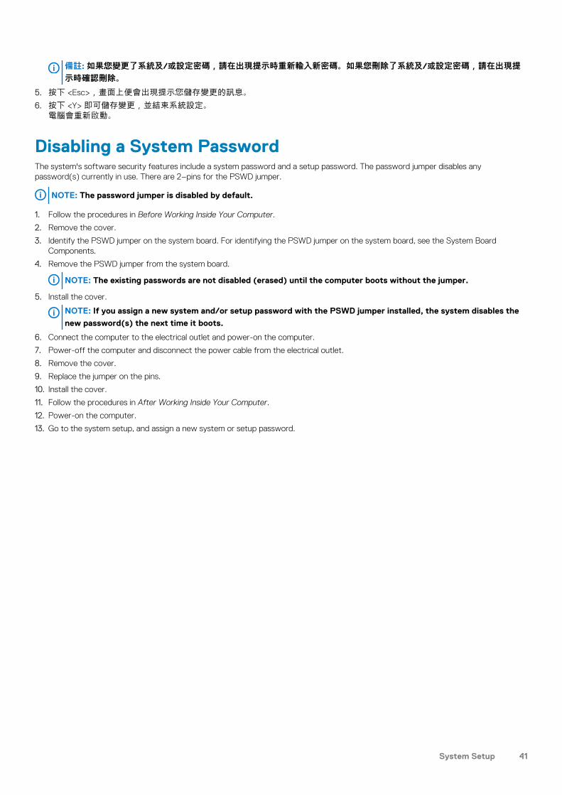
備註: 如果您變更了系統及/或設定密碼,請在出現提示時重新輸入新密碼。如果您刪除了系統及/或設定密碼,請在出現提示時確認刪除。
5. 按下 <Esc>,畫面上便會出現提示您儲存變更的訊息。
6. 按下 <Y> 即可儲存變更,並結束系統設定。電腦會重新啟動。
Disabling a System PasswordThe system's software security features include a system password and a setup password. The password jumper disables any password(s) currently in use. There are 2–pins for the PSWD jumper.
NOTE: The password jumper is disabled by default.
1. Follow the procedures in Before Working Inside Your Computer.
2. Remove the cover.
3. Identify the PSWD jumper on the system board. For identifying the PSWD jumper on the system board, see the System Board Components.
4. Remove the PSWD jumper from the system board.
NOTE: The existing passwords are not disabled (erased) until the computer boots without the jumper.
5. Install the cover.
NOTE: If you assign a new system and/or setup password with the PSWD jumper installed, the system disables the
new password(s) the next time it boots.
6. Connect the computer to the electrical outlet and power-on the computer.
7. Power-off the computer and disconnect the power cable from the electrical outlet.
8. Remove the cover.
9. Replace the jumper on the pins.
10. Install the cover.
11. Follow the procedures in After Working Inside Your Computer.
12. Power-on the computer.
13. Go to the system setup, and assign a new system or setup password.
System Setup 41

診斷如果在使用電腦時遇到問題,在聯絡 Dell 尋求技術協助之前,請先執行 ePSA 診斷。執行診斷的目的在於不使用其他設備來測試系統硬件,而不會有資料遺失的風險。如果您無法自行修正問題,維修及支援人員亦可參考診斷結果,以協助您解決問題。主題:
• Enhanced Pre-Boot System Assessment (ePSA) Diagnostics
Enhanced Pre-Boot System Assessment (ePSA) DiagnosticsThe ePSA diagnostics (also known as system diagnostics) performs a complete check of your hardware. The ePSA is embedded with the BIOS and is launched by the BIOS internally. The embedded system diagnostics provides a set of options for particular devices or device groups allowing you to:
• Run tests automatically or in an interactive mode• Repeat tests• Display or save test results• Run thorough tests to introduce additional test options to provide extra information about the failed device(s)• View status messages that inform you if tests are completed successfully• View error messages that inform you of problems encountered during testing
CAUTION: Use the system diagnostics to test only your computer. Using this program with other computers may cause
invalid results or error messages.
NOTE: Some tests for specific devices require user interaction. Always ensure that you are present at the computer
terminal when the diagnostic tests are performed.
1. Power-on the computer.
2. As the computer boots, press the <F12> key as the Dell logo appears.
3. On the boot menu screen, select the Diagnostics option.The Enhanced Pre-boot System Assessment window is displayed, listing all devices detected in the computer. The diagnostics starts running the tests on all the detected devices.
4. If you wish to run a diagnostic test on a specific device, press <Esc> and click Yes to stop the diagnostic test.
5. Select the device from the left pane and click Run Tests.
6. If there are any issues, error codes are displayed.Note the error code and contact Dell.
5
42 診斷

Troubleshooting Your Computer
Diagnostic LEDsNOTE: The diagnostic LEDs only serve as an indicator of the progress through the Power-On Self Test (POST) process.
These LEDs do not indicate the problem that caused the POST routine to stop.
The diagnostic LEDs are located on the front of the chassis next to the power button. These diagnostic LEDs are only active and visible during the POST process. Once the operating system starts to load, they turn off and are no longer visible.
Each LED has two possible states of OFF or ON. The most significant bit is labeled with the number 1, and the other three are labeled 2, 3, and 4, as you go down or across the LED stack. The normal operating condition after POST is for all four LEDs to be ON and then turn off as the BIOS hands control over to the operating system.
NOTE: The diagnostic lights will blink when the power button is amber or off, and will not blink when it is white.
Table 13. POST Diagnostic LED Patterns
Diagnostic LEDs
• The computer is either turned off or is not receiving power
• The computer is booted and operating normally.
• If the computer is turned off , connect the AC power-supply and power-on the computer.
PCI device configuration activity is in progress or PCI device failure was detected.
• Remove all peripheral cards from the PCI and PCI-E slots and reboot the computer. If the computer boots, add the peripheral cards back one by one until you find the bad one.
A possible processor failure has occurred.
• Re-seat the processor.
Memory modules are detected, but a memory power failure has occurred.
• If two or more memory modules are installed, remove the modules, then reinstall one module and re-start the computer. If the computer starts normally, continue to install additional memory modules (one at a time) until you have identified a faulty module or reinstalled all modules without error. If only one memory module is installed, try moving it to a different DIMM connector and re-start the computer.
• If available, install verified working memory of the same type into your computer.
A possible graphics card failure has occurred.
• Ensure that the display/monitor is plugged into a discrete graphic card.
• Re-seat any installed graphics cards.• If available, install a working graphics card into your computer.
A possible hard drive failure has occurred.
• Re-seat all power and data cables.
A possible USB failure has occurred
• Reinstall all USB devices and check all cable connections.
6
Troubleshooting Your Computer 43

No memory modules are detected.
• If two or more memory modules are installed, remove the modules, then reinstall one module and restart the computer. If the computer starts normally, continue to install additional memory modules (one at a time) until you have identified a faulty module or reinstalled all modules without error.
• If available, install working memory of the same type into your computer.
Power connector not installed properly.
• Re-seat the 2x2 power connector from the power supply unit.
Memory modules are detected, but a memory configuration or compatibility error has occurred.
• Ensure that no special requirements for memory module/connector placement exist.
• Ensure that the memory you are using is supported by your computer.
A possible system board resource and/or hardware failure has occurred.
• Clear CMOS (Re-seat the coin-cell battery. See Removing and Installing Coin-cell Battery).
• Disconnect all internal and external peripherals, and restart the computer. If the computer boots, add the peripheral cards back one by one until you find the bad one.
• If the problem persists, the system board / system board component is faulty.
A possible system board failure has occurred.
• Disconnect all internal and external peripherals, and re-start the computer. If the computer boots, add the peripheral cards back one by one until you find the bad one.
• If the problem persists, the system board is faulty.
Some other failure has occurred. • Ensure that the display/monitor is plugged into a discrete graphic card.
• Ensure that all hard drives and optical-drive cables are properly connected to the system board.
• If there is an error message on the screen identifying a problem with a device (such as the floppy drive or hard drive), check the device to make sure it is functioning properly.
• If the operating system is attempting to boot from a device (such as the floppy drive or optical drive), check system setup to ensure the boot sequence is correct for the devices installed on your computer.
System is in Recovery Mode • BIOS checksum failure was detected and the system is now in recovery mode.
Boot hand off • Indicates end of POST process. LEDs are normally in this state briefly as POST completes. Once the hand-off to the operating system is done, the LEDs turn off .
Error MessagesThere are two types of BIOS error messages that are displayed depending on the severity of the issue. They are:
Errors That Do Not Halt Your Computer
These error messages will not halt your computer, but will display a warning message, pause for a few seconds, and then continue to boot. The following table lists the error messages.
Table 14. Errors that do not halt your computer
Error Message
Alert! Cover was previously removed.
44 Troubleshooting Your Computer

Errors That Soft Halt Your Computer
These error messages will cause a soft halt of your computer and you will be prompted to press <F1> to continue or <F2 > to enter the system setup. The following table lists the error messages.
Table 15. — Errors that soft halt your computer
Error Message
Alert! Front I/O Cable failure.
Alert! Left Memory fan failure.
Alert! Right Memory fan failure.
Alert! PCI fan failure.
Alert! Chipset heat sink not detected.
Alert! Hard Drive fan1 failure.
Alert! Hard Drive fan2 failure.
Alert! Hard Drive fan3 failure.
Alert! CPU 0 fan failure.
Alert! CPU 1 fan failure.
Alert! Memory related failure detected.
Alert! Correctable memory error has been detected in memory slot DIMMx.
Warning: Non-optimal memory population detected. For increased memory bandwidth populate DIMM connectors with white latches before those with black latches.
Your current power supply does not support the recent configuration changes made to your system. Please contact Dell Technical support team to learn about upgrading to a higher wattage power supply.
Dell Reliable Memory Technology (RMT) has discovered and isolated errors in system memory. You may continue to work. Memory module replacement is recommended. Please refer to the RMT Event log screen in BIOS setup for specific DIMM information.
Dell Reliable Memory Technology (RMT) has discovered and isolated errors in system memory. You may continue to work. Additional errors will not be isolated. Memory module replacement is recommended. Please refer to the RMT Event log screen in BIOS setup for specific DIMM information.
Troubleshooting Your Computer 45

Technical SpecificationsNOTE: Offerings may vary by region. The following specifications are only those required by law to ship with your
computer. For comprehensive specification of your computer go to Specifications’ section in your Owner’s Manual
available on the support site at dell.com/support. For more information about the configuration of your computer, go to
Help and Support in your Windows operating system and select the option to view information about your computer.
Table 16. Processor
Feature Specification
Type 4, 6, 8, 10, and 12 core Intel Xeon E5 v2 processor.
Cache
Instruction Cache 32 KB
Data Cache • 32 KB• 256 kB Mid-Level Cache per core• Up to 30 MB last level cache (LLC) shared among all cores (2.5 MB per
core)
Table 17. System Information
Feature Specification
Chipset Intel C600 chipset
BIOS chip (NVRAM) 8 MB + 4 MB serial flash EEPROM
Table 18. Memory
Feature Specification
Memory module connector
T3610 / T5610 8 DIMM slots
T7610 16 DIMM slots
Memory module capacity
T3610 / T5610 2 GB, 4 GB, 8 GB, and 16 GB
T7610 2 GB, 4 GB, 8 GB, 16 GB, and 32 GB
Type
T3610 1600 and 1866 DDR3 RDIMM ECC/Non-ECC
T5610 1600 and 1866 DDR3 RDIMM ECC
T7610 1600 and 1866 DDR3 RDIMM and 32 GB LRDIMM ECC
Minimum memory
T3610 / T5610 / T7610 4 GB
Maximum memory
T3610 / T5610 128 GB
T7610 512 GB
7
46 Technical Specifications

Table 19. Video
Feature Specification
Discrete (PCIe 3.0/2.0 x16)
T3610 / T5610 up to 2 full-height, full-length (maximum of 300 W)
T7610 up to 4 full-height, full length (maximum of 600 W)
Table 20. Audio
Feature Specification
Integrated Realtek ALC3220 audio codec
Table 21. Network
Feature Specification
T3610 / T5610 Intel 82759
T7610 Intel 82759 and Intel 82754
Table 22. Expansion Interfaces
Feature Specification
PCI:
SLOT1 PCI Express 3.0 x8, 8 GB/s
SLOT2 PCI Express 3.0 x16, 16 GB/s
SLOT3 PCI Express 2.0 x1, 0.5 GB/s
SLOT4 PCI Express 3.0 x16, 16 GB/s
SLOT5 PCI Express 2.0 x4, 2 GB/s
SLOT6 PCI 2.3 (32 bit, 33 MHz), 133 MB/s
Storage (HDD/SSD):
SATA3-HDD0 Intel AHCI SATA 3.0, 6 Gbps
SATA3-HDD1 Intel AHCI SATA 3.0, 6 Gbps
SATA2-HDD2 Intel ACHI SATA 2.0, 3 Gbps
SATA2-HDD3 Intel ACHI SATA 2.0, 3 Gbps
Storage (ODD):
SATA2-ODD0 Intel AHCI SATA 2.0, 3 Gbps
SATA2-ODD1 Intel AHCI SATA 2.0, 3 Gbps
USB:
Front ports USB 3.0, 5 Gbps (1 port); USB 2.0, 480 Mbps (3 ports)
Rear ports USB 3.0, 5 Gbps (3 ports); USB 2.0, 480 Mbps (3 ports)
Internal ports USB 2.0, 480 Mbps (3 ports)
Table 23. Drives
Feature Specification
T3610 /T5610
Externally accessible:
Slimline SATA optical bays one
Technical Specifications 47
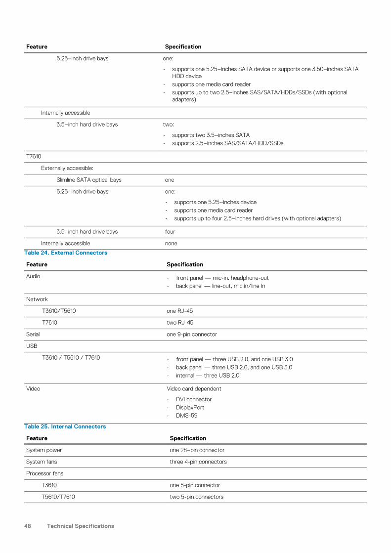
Feature Specification
5.25–inch drive bays one:
• supports one 5.25–inches SATA device or supports one 3.50–inches SATA HDD device
• supports one media card reader• supports up to two 2.5–inches SAS/SATA/HDDs/SSDs (with optional
adapters)
Internally accessible
3.5–inch hard drive bays two:
• supports two 3.5–inches SATA• supports 2.5–inches SAS/SATA/HDD/SSDs
T7610
Externally accessible:
Slimline SATA optical bays one
5.25–inch drive bays one:
• supports one 5.25–inches device• supports one media card reader• supports up to four 2.5–inches hard drives (with optional adapters)
3.5–inch hard drive bays four
Internally accessible none
Table 24. External Connectors
Feature Specification
Audio • front panel — mic-in, headphone-out• back panel — line-out, mic in/line In
Network
T3610/T5610 one RJ-45
T7610 two RJ-45
Serial one 9-pin connector
USB
T3610 / T5610 / T7610 • front panel — three USB 2.0, and one USB 3.0• back panel — three USB 2.0, and one USB 3.0• internal — three USB 2.0
Video Video card dependent
• DVI connector• DisplayPort• DMS-59
Table 25. Internal Connectors
Feature Specification
System power one 28–pin connector
System fans three 4-pin connectors
Processor fans
T3610 one 5-pin connector
T5610/T7610 two 5-pin connectors
48 Technical Specifications
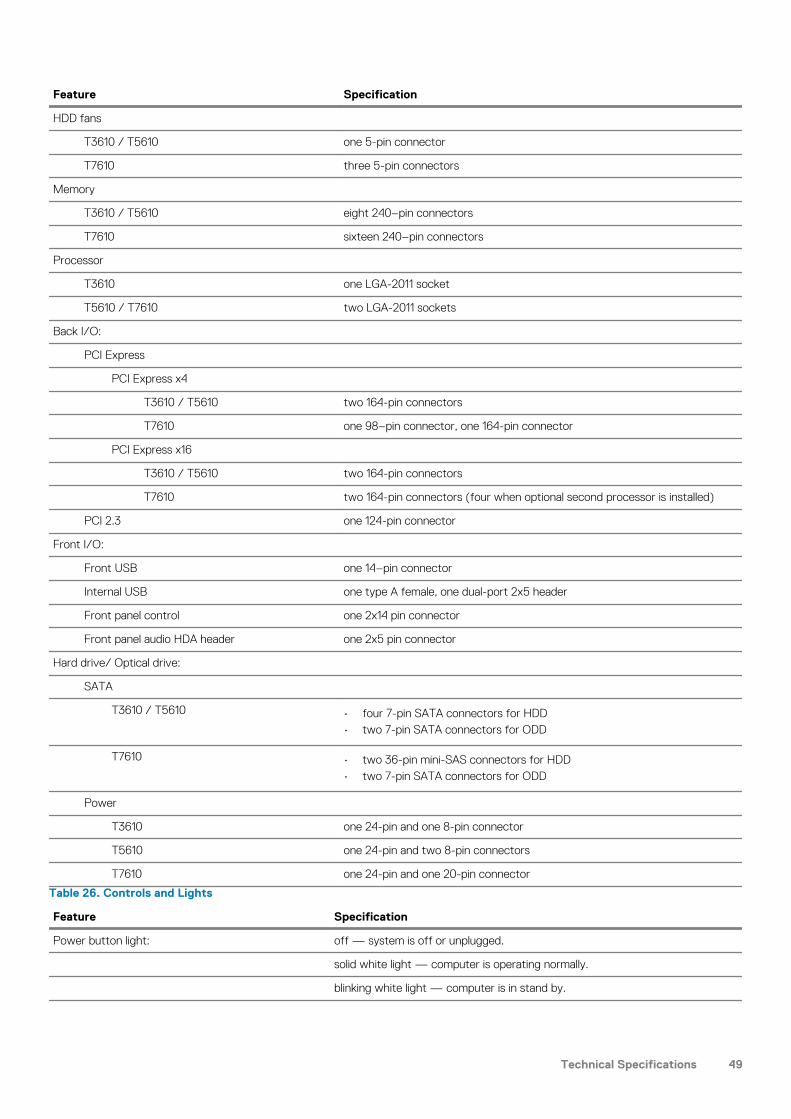
Feature Specification
HDD fans
T3610 / T5610 one 5-pin connector
T7610 three 5-pin connectors
Memory
T3610 / T5610 eight 240–pin connectors
T7610 sixteen 240–pin connectors
Processor
T3610 one LGA-2011 socket
T5610 / T7610 two LGA-2011 sockets
Back I/O:
PCI Express
PCI Express x4
T3610 / T5610 two 164-pin connectors
T7610 one 98–pin connector, one 164-pin connector
PCI Express x16
T3610 / T5610 two 164-pin connectors
T7610 two 164-pin connectors (four when optional second processor is installed)
PCI 2.3 one 124-pin connector
Front I/O:
Front USB one 14–pin connector
Internal USB one type A female, one dual-port 2x5 header
Front panel control one 2x14 pin connector
Front panel audio HDA header one 2x5 pin connector
Hard drive/ Optical drive:
SATA
T3610 / T5610 • four 7-pin SATA connectors for HDD• two 7-pin SATA connectors for ODD
T7610 • two 36-pin mini-SAS connectors for HDD• two 7-pin SATA connectors for ODD
Power
T3610 one 24-pin and one 8-pin connector
T5610 one 24-pin and two 8-pin connectors
T7610 one 24-pin and one 20-pin connector
Table 26. Controls and Lights
Feature Specification
Power button light: off — system is off or unplugged.
solid white light — computer is operating normally.
blinking white light — computer is in stand by.
Technical Specifications 49
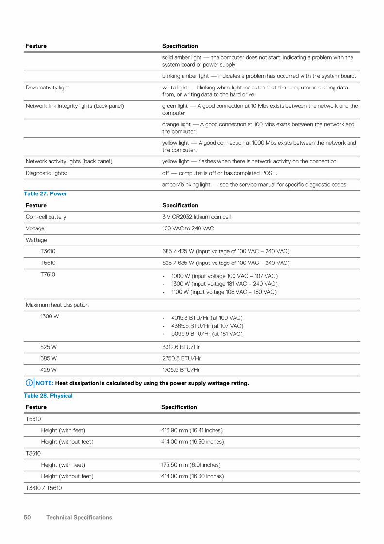
Feature Specification
solid amber light — the computer does not start, indicating a problem with the system board or power supply.
blinking amber light — indicates a problem has occurred with the system board.
Drive activity light white light — blinking white light indicates that the computer is reading data from, or writing data to the hard drive.
Network link integrity lights (back panel) green light — A good connection at 10 Mbs exists between the network and the computer
orange light — A good connection at 100 Mbs exists between the network and the computer.
yellow light — A good connection at 1000 Mbs exists between the network and the computer.
Network activity lights (back panel) yellow light — flashes when there is network activity on the connection.
Diagnostic lights: off — computer is off or has completed POST.
amber/blinking light — see the service manual for specific diagnostic codes.
Table 27. Power
Feature Specification
Coin-cell battery 3 V CR2032 lithium coin cell
Voltage 100 VAC to 240 VAC
Wattage
T3610 685 / 425 W (input voltage of 100 VAC – 240 VAC)
T5610 825 / 685 W (input voltage of 100 VAC – 240 VAC)
T7610 • 1000 W (input voltage 100 VAC – 107 VAC)• 1300 W (input voltage 181 VAC – 240 VAC)• 1100 W (input voltage 108 VAC – 180 VAC)
Maximum heat dissipation
1300 W • 4015.3 BTU/Hr (at 100 VAC)• 4365.5 BTU/Hr (at 107 VAC)• 5099.9 BTU/Hr (at 181 VAC)
825 W 3312.6 BTU/Hr
685 W 2750.5 BTU/Hr
425 W 1706.5 BTU/Hr
NOTE: Heat dissipation is calculated by using the power supply wattage rating.
Table 28. Physical
Feature Specification
T5610
Height (with feet) 416.90 mm (16.41 inches)
Height (without feet) 414.00 mm (16.30 inches)
T3610
Height (with feet) 175.50 mm (6.91 inches)
Height (without feet) 414.00 mm (16.30 inches)
T3610 / T5610
50 Technical Specifications
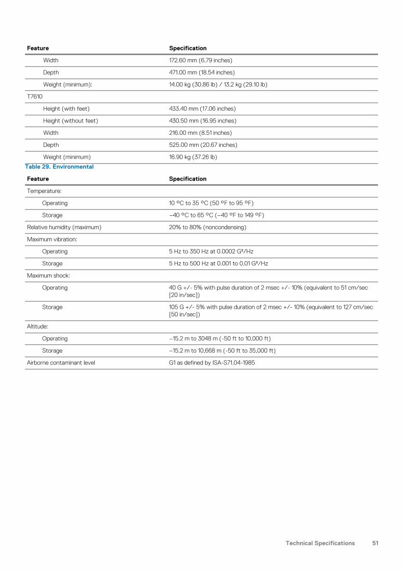
Feature Specification
Width 172.60 mm (6.79 inches)
Depth 471.00 mm (18.54 inches)
Weight (minimum): 14.00 kg (30.86 lb) / 13.2 kg (29.10 lb)
T7610
Height (with feet) 433.40 mm (17.06 inches)
Height (without feet) 430.50 mm (16.95 inches)
Width 216.00 mm (8.51 inches)
Depth 525.00 mm (20.67 inches)
Weight (minimum) 16.90 kg (37.26 lb)
Table 29. Environmental
Feature Specification
Temperature:
Operating 10 °C to 35 °C (50 °F to 95 °F)
Storage –40 °C to 65 °C (–40 °F to 149 °F)
Relative humidity (maximum) 20% to 80% (noncondensing)
Maximum vibration:
Operating 5 Hz to 350 Hz at 0.0002 G²/Hz
Storage 5 Hz to 500 Hz at 0.001 to 0.01 G²/Hz
Maximum shock:
Operating 40 G +/- 5% with pulse duration of 2 msec +/- 10% (equivalent to 51 cm/sec [20 in/sec])
Storage 105 G +/- 5% with pulse duration of 2 msec +/- 10% (equivalent to 127 cm/sec [50 in/sec])
Altitude:
Operating –15.2 m to 3048 m (-50 ft to 10,000 ft)
Storage –15.2 m to 10,668 m (-50 ft to 35,000 ft)
Airborne contaminant level G1 as defined by ISA-S71.04-1985
Technical Specifications 51
聯絡 Dell
備註: 如果您沒有有效的互聯網連線,則您可以在購機發票、裝箱單、賬單或 Dell 產品目錄中找到聯絡資料。
Dell 提供多種線上和電話支援與服務選項。可用性依國家/地區及產品而異,且某些服務在您所在地區可能無法使用。如需聯絡 Dell 解決銷售、技術支援和客戶服務問題,請:
1. 轉至 support.dell.com。
2. 選擇您的支援類別。
3. 在頁面底部的選擇國家/地區下拉清單中確認您所在國家或地區。
4. 根據您的需求選擇相應服務或支援連結。
8
52 聯絡 Dell