Embed Size (px)
Citation preview
Department of Mechanical Engineering
ME 6512 – THERMAL ENGINEERING LABOURATORY - II [MANUAL CUM OBSERVATION]
Name : ……………………………………………......
Reg.No : ……………………………………………......
Branch : ……………………………………………......
Year & Semester : ……………………………………………......
www.studentsfocus.com
2
Department of Mechanical Engineering
ME 6512 – THERMAL ENGINEERING LABOURATORY - II [MANUAL CUM OBSERVATION]
III – Year / V – Semester
www.studentsfocus.com
VI Semester Thermal Engineering Lab – II (Manual Cum Observation)
3
Table of Contents
Sl.No.
Date
Name of the Experiment
Mark
Staff Signature
1.
2.
3.
4.
5.
6.
7.
8.
9.
10.
11.
Completed date: Staff - in - charge Average Mark:
www.studentsfocus.com
VI Semester Thermal Engineering Lab – II (Manual Cum Observation)
4
Ex: No: HEAT TRANSFER IN FORCED CONVECTION Date:
Aim:
To determine the heat transfer co-efficient by using forced convection Apparatus.
Apparatus Required:
(i) Experimental setup
(ii) Thermocouples
(iii) U – tube manometer
Theory:
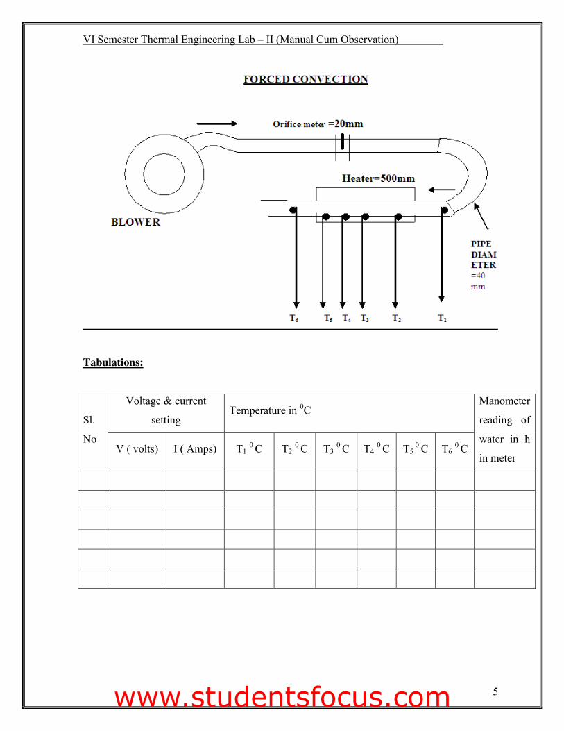
Apparatus consist of blower unit fitted with the test pipe. The test section is surrounded by
Nichrome band heater. Four thermocouples are embedded on the test section and two
thermocouples are placed in the air stream at the entrance and exit of the test section to
measure the air temperature. Test pipe is connected to the delivery side of the blower along
with the orifice to measure flow of air through the pipe. Input to the heater is given through a
dimmerstat and measured by meters. It is to be noted that only a part of the total heat
supplied is utilized in heating the air. A temperature indicator with cold junction
compensation is provided to measure temperatures of pipe wall at various points in the test
section. Air flow is measured with the help of orifice meter and the water manometer fitted
on the board.
www.studentsfocus.com
VI Semester Thermal Engineering Lab – II (Manual Cum Observation)
5
Tabulations:
Sl.
No
Voltage & current
setting Temperature in 0C
Manometer
reading of
water in h
in meter V ( volts) I ( Amps) T1 0 C T2 0 C T3 0 C T4 0 C T5
0 C T6 0 C
www.studentsfocus.com
VI Semester Thermal Engineering Lab – II (Manual Cum Observation)
6
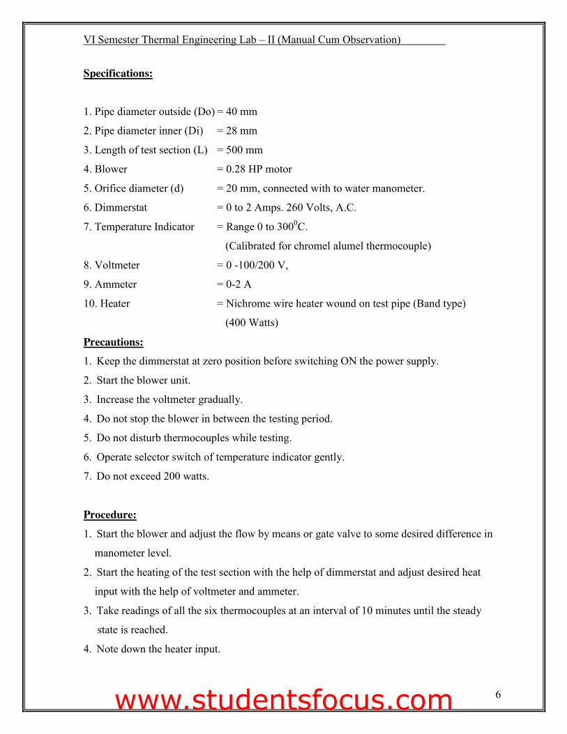
Specifications:
1. Pipe diameter outside (Do) = 40 mm
2. Pipe diameter inner (Di) = 28 mm
3. Length of test section (L) = 500 mm
4. Blower = 0.28 HP motor
5. Orifice diameter (d) = 20 mm, connected with to water manometer.
6. Dimmerstat = 0 to 2 Amps. 260 Volts, A.C.
7. Temperature Indicator = Range 0 to 3000C.
(Calibrated for chromel alumel thermocouple)
8. Voltmeter = 0 -100/200 V,
9. Ammeter = 0-2 A
10. Heater = Nichrome wire heater wound on test pipe (Band type)
(400 Watts)
Precautions: 1. Keep the dimmerstat at zero position before switching ON the power supply.
2. Start the blower unit.
3. Increase the voltmeter gradually.
4. Do not stop the blower in between the testing period.
5. Do not disturb thermocouples while testing.
6. Operate selector switch of temperature indicator gently.
7. Do not exceed 200 watts.
Procedure: 1. Start the blower and adjust the flow by means or gate valve to some desired difference in
manometer level.
2. Start the heating of the test section with the help of dimmerstat and adjust desired heat
input with the help of voltmeter and ammeter.
3. Take readings of all the six thermocouples at an interval of 10 minutes until the steady
state is reached.
4. Note down the heater input.
www.studentsfocus.com

VI Semester Thermal Engineering Lab – II (Manual Cum Observation)
7
Model Calculation:
www.studentsfocus.com
VI Semester Thermal Engineering Lab – II (Manual Cum Observation)
8
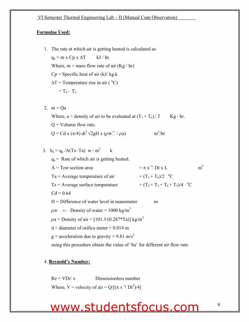
Formulae Used: 1. The rate at which air is getting heated is calculated as
qa = m x Cp x ∆T kJ / hr.
Where, m = mass flow rate of air (Kg / hr)
Cp = Specific heat of air (kJ/ kg.k
∆T = Temperature rise in air ( oC)
= T6 – T1.
2. m = Qa
Where, a = density of air to be evaluated at (T1 + T6)./ 2 Kg / hr.
Q = Volume flow rate.
Q = Cd x (S��) di2 �2gH x (U / Ua) m3/hr
3. ha = qa /A(Ts- Ta) w / m2 k
qa = Rate of which air is getting heated.
A = Test section area = S x Di x L m2
Ta = Average temperature of air = (T1 + T6)/2 oC
Ts = Average surface temperature = (T2 + T3 + T4 + T5)/4 oC
Cd = 0.64
H = Difference of water level in manometer m
Uw Density of water = 1000 kg/m3
Ua = Density of air = [101.3/(0.287*Ta)] kg/m3
d = diameter of orifice meter = 0.014 m
g = acceleration due to gravity = 9.81 m/s2
using this procedure obtain the value of ‘ha’ for different air flow rate.
4. Reynold’s Number:
Re = VDi/ υ Dimensionless number
Where, V = velocity of air = Q/[(S Di2)/4]
www.studentsfocus.com

ME 2355 VI Semester Thermal Engineering Lab – II (Manual Cum Observation)
9
Model Calculation:
www.studentsfocus.com
ME 2355 VI Semester Thermal Engineering Lab – II (Manual Cum Observation)
10
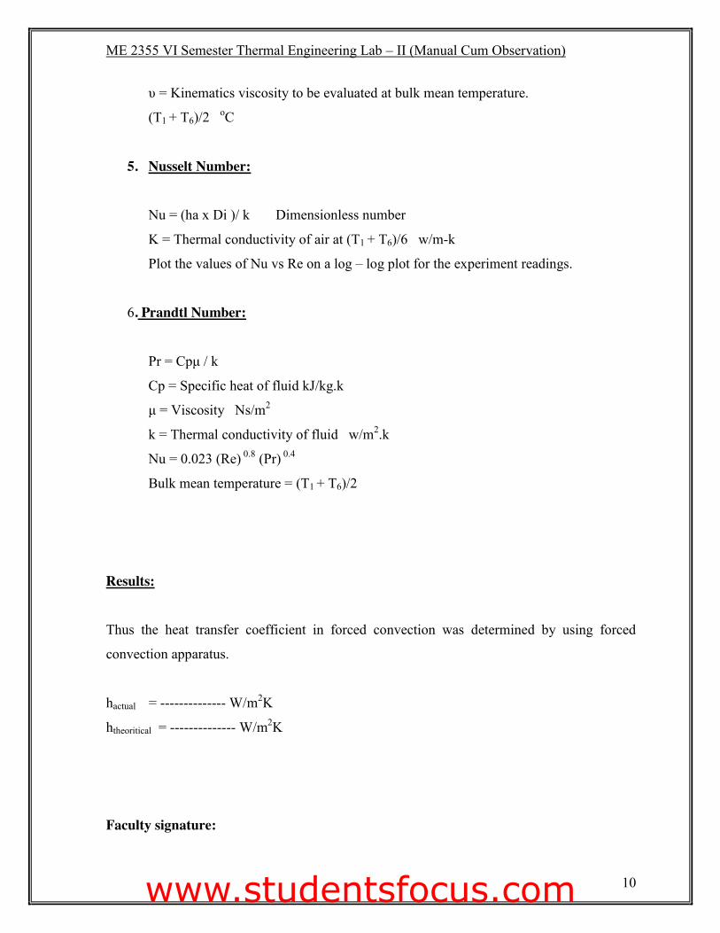
υ = Kinematics viscosity to be evaluated at bulk mean temperature.
(T1 + T6)/2 oC
5. Nusselt Number:
Nu = (ha x Di )/ k Dimensionless number
K = Thermal conductivity of air at (T1 + T6)/6 w/m-k
Plot the values of Nu vs Re on a log – log plot for the experiment readings.
6. Prandtl Number:
Pr = Cpμ / k
Cp = Specific heat of fluid kJ/kg.k
μ = Viscosity Ns/m2
k = Thermal conductivity of fluid w/m2.k
Nu = 0.023 (Re) 0.8 (Pr) 0.4
Bulk mean temperature = (T1 + T6)/2
Results: Thus the heat transfer coefficient in forced convection was determined by using forced
convection apparatus.
hactual = -------------- W/m2K
htheoritical = -------------- W/m2K
Faculty signature:
www.studentsfocus.com

ME 2355 VI Semester Thermal Engineering Lab – II (Manual Cum Observation)
11
www.studentsfocus.com
ME 2355 VI Semester Thermal Engineering Lab – II (Manual Cum Observation)
12
Ex: No: HEAT TRANSFER TO LAGGED PIPE APPARATUS Date:
Aim: To determine the heat transfer through lagged pipe using lagged pipe apparatus.
Apparatus Required: (i) Experimental setup
(ii) Lagged pipe apparatus
(iii) Thermocouple
(iv) Ammeter
(v) Voltmeter
Theory: The insulation is defined as a material which retards the heat flow with reasonable
effectiveness. Heat is transferred through insulation by conduction, convection and radiation
or by the combination of these three. There is no insulation which is 100 % effective to
prevent the flow of heat under temperature gradient.
The experimental set-up in which the heat is transferred through insulation by conduction is
understudy in the given apparatus. The apparatus consisting of a rod heater with asbestos
lagging. The assembly is inside an MS pipe. Between the asbestos lagging and MS pipe, saw
dust is filled.
www.studentsfocus.com
ME 2355 VI Semester Thermal Engineering Lab – II (Manual Cum Observation)
13
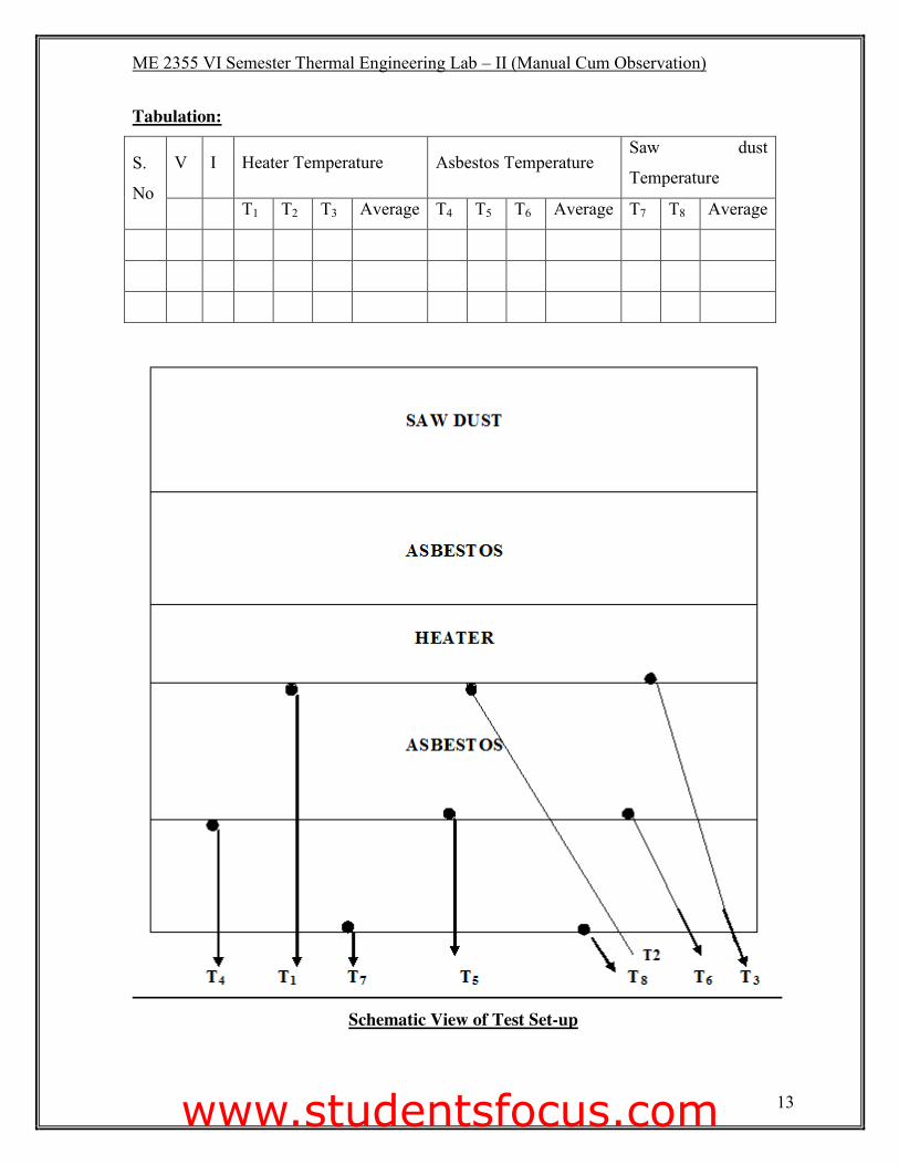
Tabulation:
S.
No
V I Heater Temperature Asbestos Temperature Saw dust
Temperature
T1 T2 T3 Average T4 T5 T6 Average T7 T8 Average
Schematic View of Test Set-up
www.studentsfocus.com
ME 2355 VI Semester Thermal Engineering Lab – II (Manual Cum Observation)
14
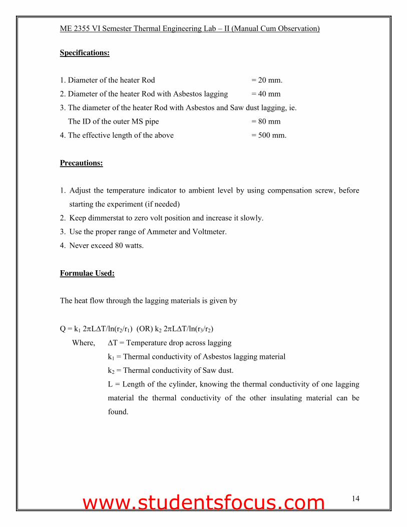
Specifications:
1. Diameter of the heater Rod = 20 mm.
2. Diameter of the heater Rod with Asbestos lagging = 40 mm
3. The diameter of the heater Rod with Asbestos and Saw dust lagging, ie.
The ID of the outer MS pipe = 80 mm
4. The effective length of the above = 500 mm.
Precautions:
1. Adjust the temperature indicator to ambient level by using compensation screw, before
starting the experiment (if needed)
2. Keep dimmerstat to zero volt position and increase it slowly.
3. Use the proper range of Ammeter and Voltmeter.
4. Never exceed 80 watts.
Formulae Used:
The heat flow through the lagging materials is given by
Q = k1 2SL∆T/ln(r2/r1) (OR) k2 2SL∆T/ln(r3/r2)
Where, ∆T = Temperature drop across lagging
k1 = Thermal conductivity of Asbestos lagging material
k2 = Thermal conductivity of Saw dust.
L = Length of the cylinder, knowing the thermal conductivity of one lagging
material the thermal conductivity of the other insulating material can be
found.
www.studentsfocus.com

ME 2355 VI Semester Thermal Engineering Lab – II (Manual Cum Observation)
15
Model Calculation:
www.studentsfocus.com
ME 2355 VI Semester Thermal Engineering Lab – II (Manual Cum Observation)
16
Procedure:
1. Switch ON the units and check if all channels of temperature indicator showing proper
temperature.
2. Switch ON the heater using the regulator and keep the power input at some particular
value.
3. Allow the unit to stabilize for about 20 to 30 minutes.
4. Now note down the Ammeter, Voltmeter reading which gives the heat input.
5. Temperature 1,2 and 3 the temperature of heater Rod, 4,5 and 6 temperature on the
asbestos layer, 7 and 8 temperatures on the saw dust lagging.
6. The average temperature of each cylinder is taken for calculation. The temperatures are
measured by thermocouples (Fe/Ko) with multipoint digital temperature indicator.
7. The experiment may be repeat for different heat inputs.
Results: The heat transfer through lagging material = ____________________ W.
The thermal conductivity of resistive material = _________________ W /m2-K
Faculty Signature:
www.studentsfocus.com

ME 2355 VI Semester Thermal Engineering Lab – II (Manual Cum Observation)
17
www.studentsfocus.com
ME 2355 VI Semester Thermal Engineering Lab – II (Manual Cum Observation)
18
Ex: No: HEAT TRANSFER IN A PIN FIN (FORCED) APPARATUS Date: Aim: To determine the pin-fin efficiency and heat flow of pin-fin forced convection
Apparatus required:
(i) Experimental setup
(ii) Thermocouples
(iii) U – tube manometer
Theory:
A brass fin of consist of circular cross section is fitted across a long rectangular duct. The
other end of the duct is connected to the suction side of a blower and the air blows past the
fin perpendicular to its axis. One end of the fin projects outside the duct and is heated by a
heater. Temperatures at five points along the length of the fin are measured by chrome
alumel thermocouples connected along the length of the fin. The air flow rate is measured by
an orifice meter fitted on the delivery side of the blower. Schematic diagram of the set up is
shown in fig. while the details of the pin fin are shown.
www.studentsfocus.com
ME 2355 VI Semester Thermal Engineering Lab – II (Manual Cum Observation)
19
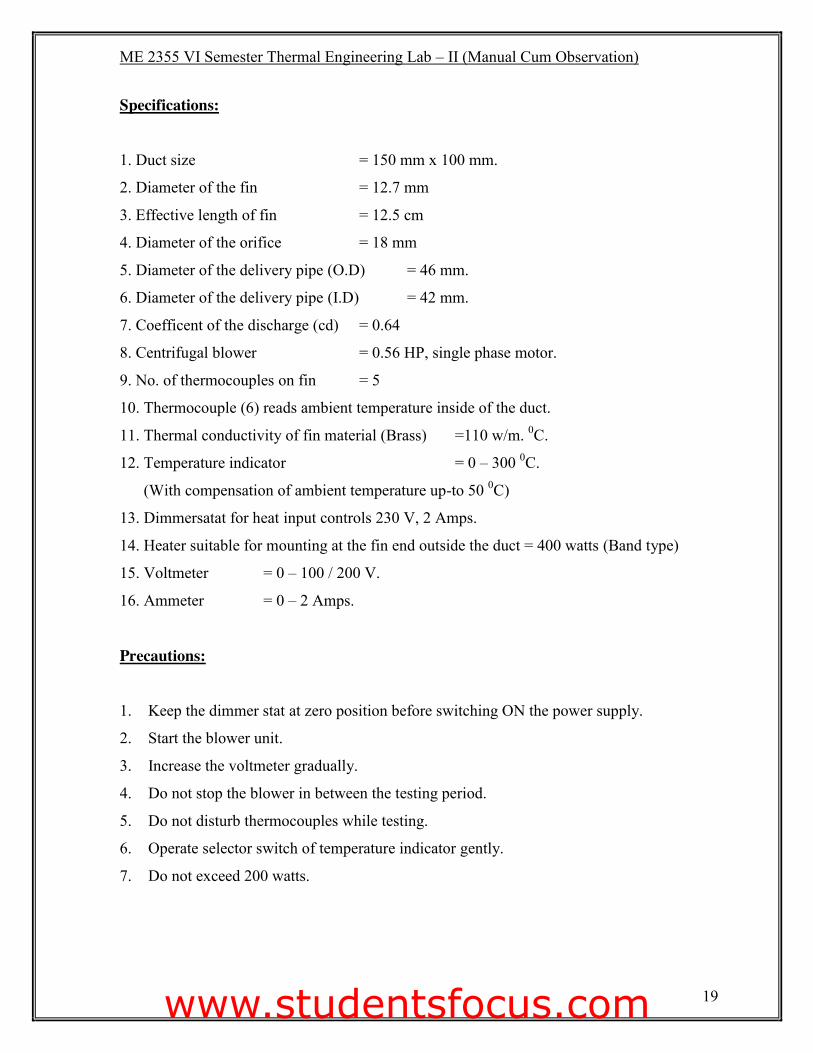
Specifications:
1. Duct size = 150 mm x 100 mm.
2. Diameter of the fin = 12.7 mm
3. Effective length of fin = 12.5 cm
4. Diameter of the orifice = 18 mm
5. Diameter of the delivery pipe (O.D) = 46 mm.
6. Diameter of the delivery pipe (I.D) = 42 mm.
7. Coefficent of the discharge (cd) = 0.64
8. Centrifugal blower = 0.56 HP, single phase motor.
9. No. of thermocouples on fin = 5
10. Thermocouple (6) reads ambient temperature inside of the duct.
11. Thermal conductivity of fin material (Brass) =110 w/m. 0C.
12. Temperature indicator = 0 – 300 0C.
(With compensation of ambient temperature up-to 50 0C)
13. Dimmersatat for heat input controls 230 V, 2 Amps.
14. Heater suitable for mounting at the fin end outside the duct = 400 watts (Band type)
15. Voltmeter = 0 – 100 / 200 V.
16. Ammeter = 0 – 2 Amps.
Precautions:
1. Keep the dimmer stat at zero position before switching ON the power supply.
2. Start the blower unit.
3. Increase the voltmeter gradually.
4. Do not stop the blower in between the testing period.
5. Do not disturb thermocouples while testing.
6. Operate selector switch of temperature indicator gently.
7. Do not exceed 200 watts.
www.studentsfocus.com
ME 2355 VI Semester Thermal Engineering Lab – II (Manual Cum Observation)
20
Procedure: Forced Convection:
1. Start heating the fin by switching ON the heater element and adjust the voltage on
dimmerstat to say 100 volts.
2. Start the Blower and adjust the difference of level in the manometer with the help of gate
valve.
3. Note down the thermocouple readings 1 to 5 at a time interval of 5 minutes.
4. When steady state is reached, record the final readings 1 to 5 and also record the ambient
temperature reading 6.
5. Repeat the same experiment with different manometer readings.
Formulae Used :( Forced Convection)
1. Film Temperature Tf = ( Tα + Tw) / 2
Where, Tα = surface temperature (T6)
Tw = (T1 + T2 + T3 + T4 + T5) / 5 (average temperature of fin)
2. Discharge of air Q = Cd x {(S 2) /4}��gha m3/s.
Where, ha (head of air) = (Uw / Ua) x H m
H = Difference of water level in manometer m
U 3
Ua = Density of air = 1.165 kg/m3
g = acceleration due to gravity = 9.81 m/s2
Cd = Coefficient of discharge = 0.64
D = diameter of the orifice
3. Velocity of air, V = Q/A m/s
Where Q = discharge of air
A = area of the duct
www.studentsfocus.com
ME 2355 VI Semester Thermal Engineering Lab – II (Manual Cum Observation)
21
Tabulations:
Forced convection:
S. No V I Manometer
reading Fin Temperatures
Ambient
Temp
h1 h2 T1 T2 T3 T4 T5 T6
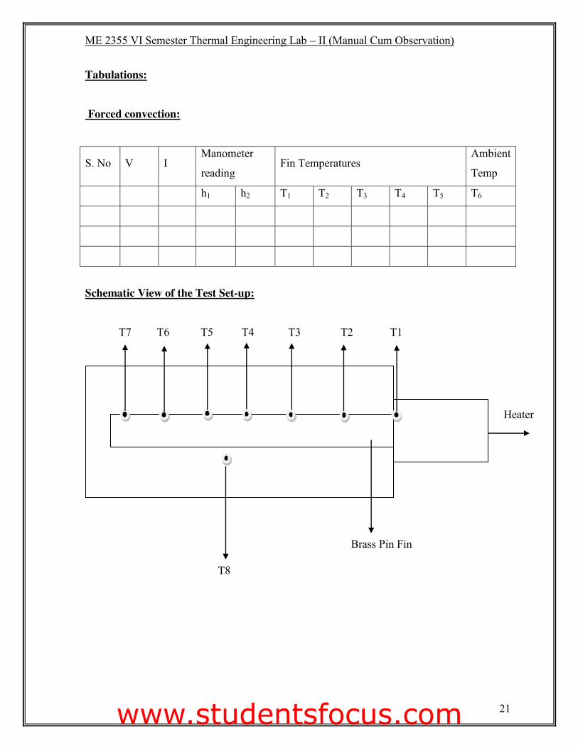
Schematic View of the Test Set-up:
T7 T6 T5 T4 T3 T2 T1
T8
Brass Pin Fin
Heater
www.studentsfocus.com
ME 2355 VI Semester Thermal Engineering Lab – II (Manual Cum Observation)
22
4. Reynold’s Number:
Re = Vmf D/ υ Dimensionless number
Where, Vmf = velocity of air at mean film temp. = VTf/ Tα
D = diameter of the fin
υ = Kinematics viscosity to be evaluate at average of bulk mean temperature.
(T1 + T6) / 2 oC
5. Heat transfer coefficient, h = Nu k / D
Where Nu = Nusselt Number
6. Nusselt Number:
Nu = CRem (Pr)0.33
7. Heat flow, Q = �hpkA x (Tw – TD) tan h (mL)
h = heat transfer coefficient,
Where, p = perimeter in m
k= 386 w/mk
m= ��hp/kA)
A = area of fin = (S 2) /4
L = Length of the fin
Tw – average temperature
TD – ambient (surface) temperature (T6)
8. Efficiency, K = {tan h (mL)}/ mL
www.studentsfocus.com

ME 2355 VI Semester Thermal Engineering Lab – II (Manual Cum Observation)
23
Model Calculation:
www.studentsfocus.com
ME 2355 VI Semester Thermal Engineering Lab – II (Manual Cum Observation)
24
Results: Thus the experiment was conducted and results found were
Pin fin Efficiency, K�� �BBBBBBBBBBB��
Heat transfer, Q = ___________ W
Faculty Signature:
www.studentsfocus.com

ME 2355 VI Semester Thermal Engineering Lab – II (Manual Cum Observation)
25 www.studentsfocus.com
ME 2355 VI Semester Thermal Engineering Lab – II (Manual Cum Observation)
26
Ex: No: HEAT TRANSFER IN NATURAL CONVECTION Date: Aim: To find the surface heat transfer co-efficient for a vertical tube losing heat by natural
convection.
Apparatus Required: (i) Experimental setup
(ii) Thermocouple
(iii) Ammeter
(iv) Voltmeter
Theory: The apparatus consist of a brass tube fitted in a rectangular duct in a vertical fashion. The
duct is open at the top and bottom, and forms an enclosure and serves the purpose of
undisturbed surroundings. One side of the duct is made up of Perspex for visualization. An
electric heating element is kept in the vertical tube which in turn heats the tube surface. The
heat is lost from the tube to the surrounding air by natural convection. The temperature of the
vertical tube is measured by seven thermocouples. The heat input to the heater is measured
by an Ammeter and a Voltmeter and is varied by a dimmerstat.
When a hot body is kept in a still atmosphere, heat is transferred to surrounding fluid by
natural convection. The fluid layer in contact with the hot body gets heated, rises up due to
the decrease in its density and the cold fluid rushes in from bottom side. The process is
continuous and the heat transfer takes place due to the relative motion of hot and cold fluid
particles.
www.studentsfocus.com
ME 2355 VI Semester Thermal Engineering Lab – II (Manual Cum Observation)
27
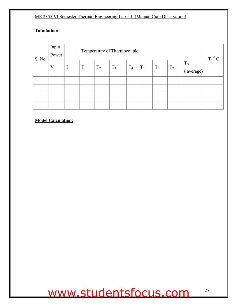
Tabulation:
S. No
Input
Power Temperature of Thermocouple
Ta 0 C
V I T1 T2 T3 T4 T5 T6 T7 TS
( average)
Model Calculation:
www.studentsfocus.com
ME 2355 VI Semester Thermal Engineering Lab – II (Manual Cum Observation)
28
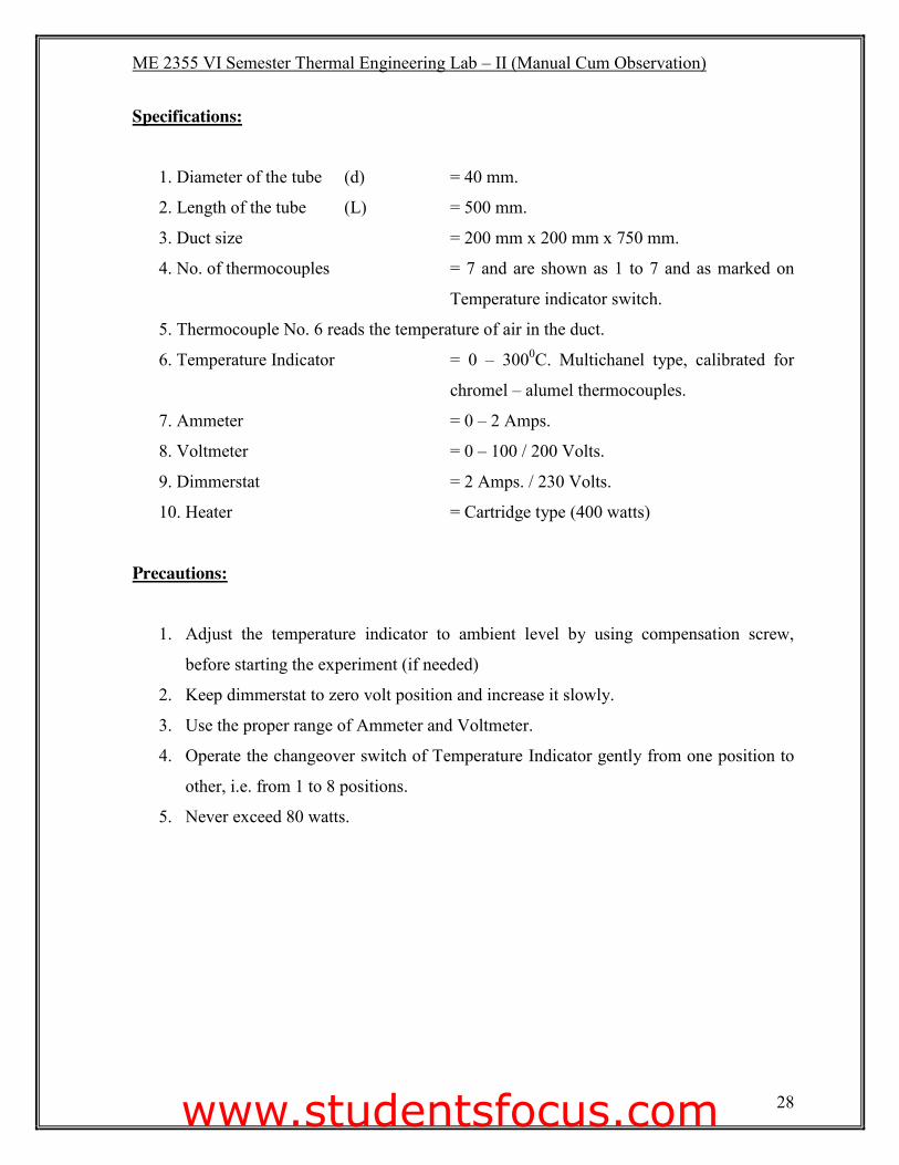
Specifications: 1. Diameter of the tube (d) = 40 mm.
2. Length of the tube (L) = 500 mm.
3. Duct size = 200 mm x 200 mm x 750 mm.
4. No. of thermocouples = 7 and are shown as 1 to 7 and as marked on
Temperature indicator switch.
5. Thermocouple No. 6 reads the temperature of air in the duct.
6. Temperature Indicator = 0 – 3000C. Multichanel type, calibrated for
chromel – alumel thermocouples.
7. Ammeter = 0 – 2 Amps.
8. Voltmeter = 0 – 100 / 200 Volts.
9. Dimmerstat = 2 Amps. / 230 Volts.
10. Heater = Cartridge type (400 watts)
Precautions:
1. Adjust the temperature indicator to ambient level by using compensation screw,
before starting the experiment (if needed)
2. Keep dimmerstat to zero volt position and increase it slowly.
3. Use the proper range of Ammeter and Voltmeter.
4. Operate the changeover switch of Temperature Indicator gently from one position to
other, i.e. from 1 to 8 positions.
5. Never exceed 80 watts.
www.studentsfocus.com
ME 2355 VI Semester Thermal Engineering Lab – II (Manual Cum Observation)
29
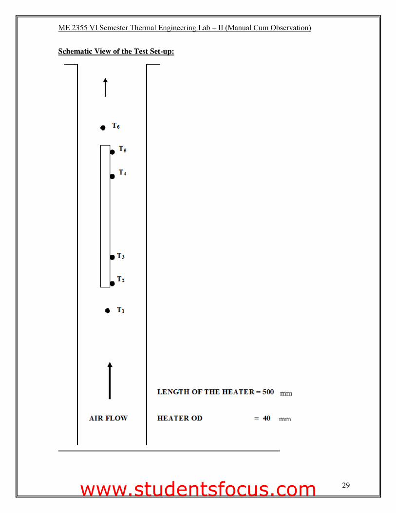
Schematic View of the Test Set-up:
mm
mm
www.studentsfocus.com
ME 2355 VI Semester Thermal Engineering Lab – II (Manual Cum Observation)
30
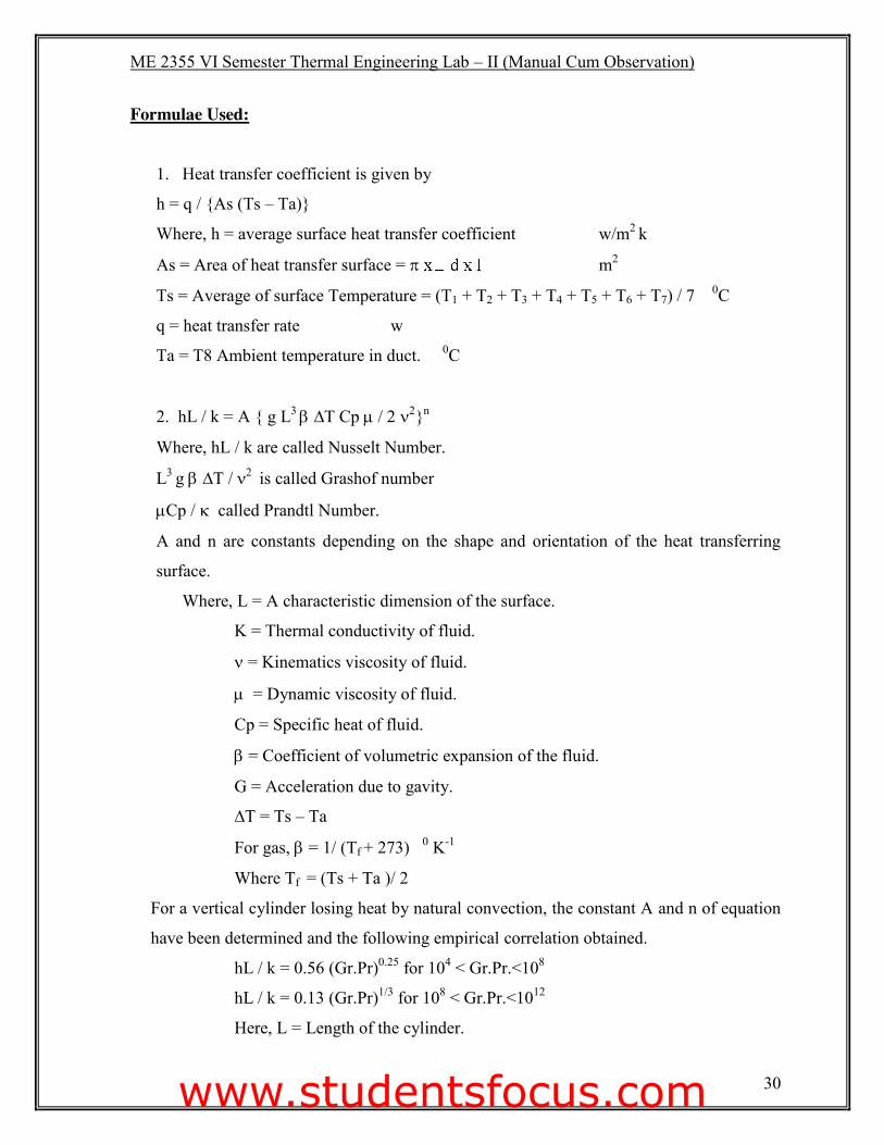
Formulae Used: 1. Heat transfer coefficient is given by
h = q / {As (Ts – Ta)}
Where, h = average surface heat transfer coefficient w/m2 k
As = Area of heat transfer surface = S m2
Ts = Average of surface Temperature = (T1 + T2 + T3 + T4 + T5 + T6 + T7) / 7 0C
q = heat transfer rate w
Ta = T8 Ambient temperature in duct. 0C
2. hL / k = A { g L3 E�∆T Cp P�����Q�`n
Where, hL / k are called Nusselt Number.
L3 g�E�∆T / Q�� is called Grashof number
PCp ��N��called Prandtl Number.
A and n are constants depending on the shape and orientation of the heat transferring
surface.
Where, L = A characteristic dimension of the surface.
K = Thermal conductivity of fluid.
Q = Kinematics viscosity of fluid.
P� = Dynamic viscosity of fluid.
Cp = Specific heat of fluid.
E = Coefficient of volumetric expansion of the fluid.
G = Acceleration due to gavity.
∆T = Ts – Ta
For gas, E�= 1/ (Tf + 273) 0 K-1
Where Tf = (Ts + Ta )/ 2
For a vertical cylinder losing heat by natural convection, the constant A and n of equation
have been determined and the following empirical correlation obtained.
hL / k = 0.56 (Gr.Pr)0.25 for 104 < Gr.Pr.<108
hL / k = 0.13 (Gr.Pr)1/3 for 108 < Gr.Pr.<1012
Here, L = Length of the cylinder.
www.studentsfocus.com

ME 2355 VI Semester Thermal Engineering Lab – II (Manual Cum Observation)
31
Model Calculation:
www.studentsfocus.com
ME 2355 VI Semester Thermal Engineering Lab – II (Manual Cum Observation)
32
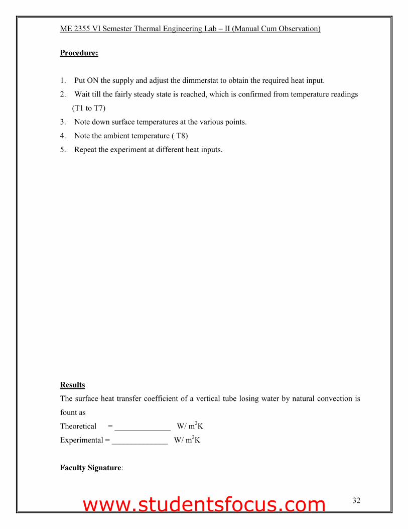
Procedure: 1. Put ON the supply and adjust the dimmerstat to obtain the required heat input.
2. Wait till the fairly steady state is reached, which is confirmed from temperature readings
(T1 to T7)
3. Note down surface temperatures at the various points.
4. Note the ambient temperature ( T8)
5. Repeat the experiment at different heat inputs.
Results The surface heat transfer coefficient of a vertical tube losing water by natural convection is
fount as
Theoretical = ______________ W/ m2K
Experimental = ______________ W/ m2K
Faculty Signature:
www.studentsfocus.com

ME 2355 VI Semester Thermal Engineering Lab – II (Manual Cum Observation)
33
www.studentsfocus.com

ME 2355 VI Semester Thermal Engineering Lab – II (Manual Cum Observation)
34
Ex: No: EMISSIVITY MEASUREMENT APPARATUS Date:
Aim :
To measure the property of emissivity of the test plate surface at various temperature.
Apparatus required:
(i) Experimental setup
(ii) Thermocouples
(iii) U – tube manometer
Theory:
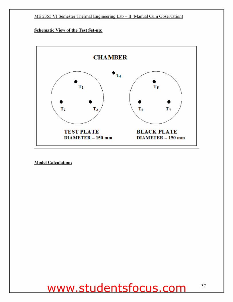
The experiment set up consists of two circular aluminum plates identical in size and are
provided with heating coils sandwiched. The plates are mounted on brackets and are kept in
an enclosure so as to provide undistributed natural convection surroundings. The heat input
to the heater is varied by separate Dimmerstats and is measured by using an ammeter and
voltmeter with the help of double pole double throw switch. The temperatures of the plates
are measured by thermocouples. Plates (1) is blackened by a thick layer of lamp black to
form the idealized black surface whereas the plate (2) is the test plate whose Emissivity is to
be determined.
www.studentsfocus.com
ME 2355 VI Semester Thermal Engineering Lab – II (Manual Cum Observation)
35
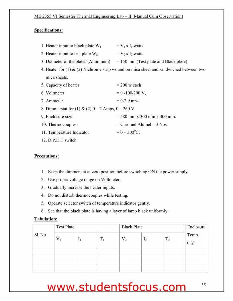
Specifications: 1. Heater input to black plate W1 = V1 x I1 watts
2. Heater input to test plate W2 = V2 x I2 watts
3. Diameter of the plates (Aluminum) = 150 mm (Test plate and Black plate)
4. Heater for (1) & (2) Nichrome strip wound on mica sheet and sandwiched between two
mica sheets.
5. Capacity of heater = 200 w each
6. Voltmeter = 0 -100/200 V,
7. Ammeter = 0-2 Amps
8. Dimmerstat for (1) & (2) 0 – 2 Amps, 0 – 260 V
9. Enclosure size = 580 mm x 300 mm x 300 mm.
10. Thermocouples = Chromel Alumel – 3 Nos.
11. Temperature Indicator = 0 – 3000C.
12. D.P.D.T switch
Precautions:
1. Keep the dimmerstat at zero position before switching ON the power supply.
2. Use proper voltage range on Voltmeter.
3. Gradually increase the heater inputs.
4. Do not disturb thermocouples while testing.
5. Operate selector switch of temperature indicator gently.
6. See that the black plate is having a layer of lamp black uniformly.
Tabulation:
Sl. No
Test Plate Black Plate Enclosure
Temp.
(T3) V1 I1 T1 V2 I2 T2
www.studentsfocus.com
ME 2355 VI Semester Thermal Engineering Lab – II (Manual Cum Observation)
36
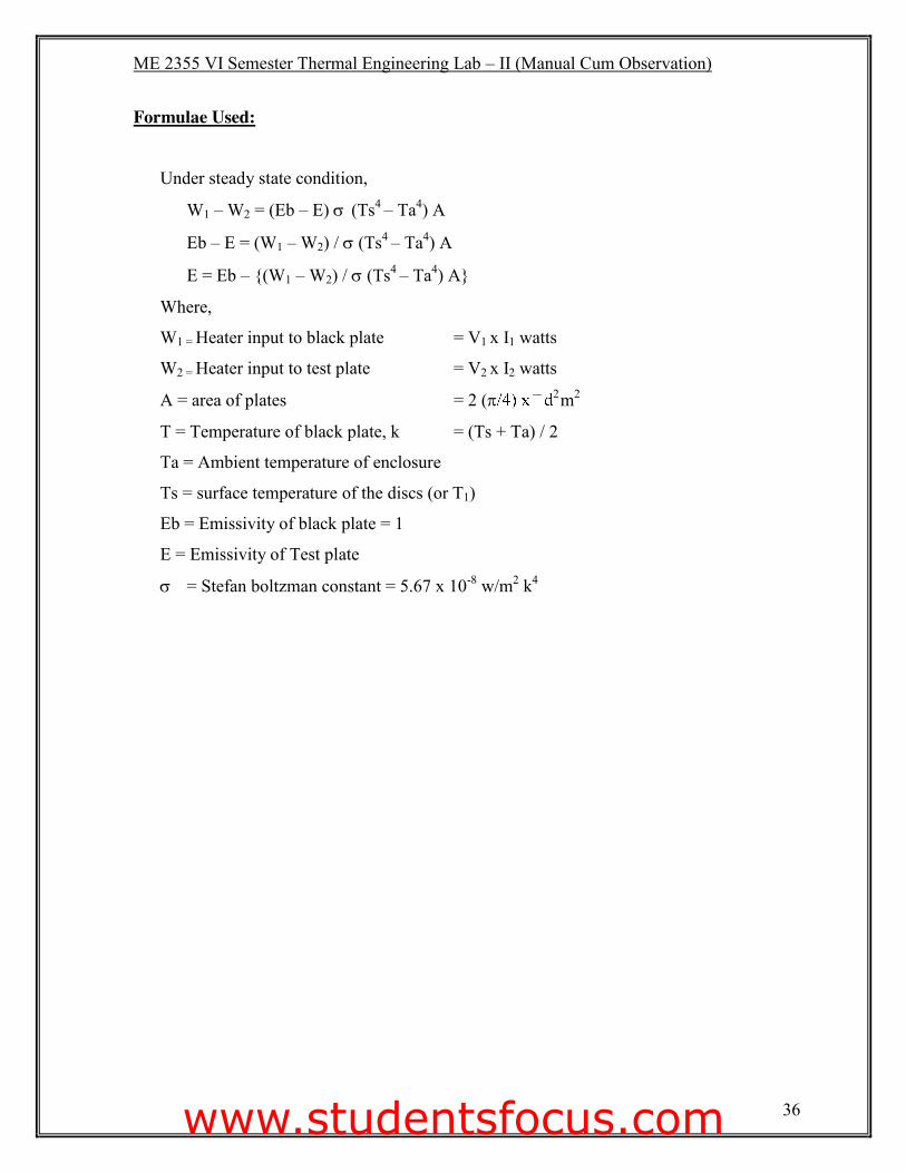
Formulae Used: Under steady state condition,
W1 – W2 = (Eb – E) V (Ts4 – Ta4) A
Eb – E = (W1 – W2) / V (Ts4 – Ta4) A
E = Eb – {(W1 – W2) / V (Ts4 – Ta4) A}
Where,
W1 = Heater input to black plate = V1 x I1 watts
W2 = Heater input to test plate = V2 x I2 watts
A = area of plates = 2 (S 2 m2
T = Temperature of black plate, k = (Ts + Ta) / 2
Ta = Ambient temperature of enclosure
Ts = surface temperature of the discs (or T1)
Eb = Emissivity of black plate = 1
E = Emissivity of Test plate
V = Stefan boltzman constant = 5.67 x 10⁻⁸ w/m2 k4
www.studentsfocus.com
ME 2355 VI Semester Thermal Engineering Lab – II (Manual Cum Observation)
37
Schematic View of the Test Set-up:
Model Calculation:
www.studentsfocus.com
ME 2355 VI Semester Thermal Engineering Lab – II (Manual Cum Observation)
38
Procedure:
1. Gradually increase the input to the heater to black plate and adjust it to some value viz.
30, 50, 75 watts. And adjust the heater input to test plate slightly less than the black plate
27, 35, 55 watts. Etc.
2. Check the temperature of the two plates with small time intervals and adjust the input of
test plate only, by the dimmerstat so that the two plates will be maintained at the same
temperature.
3. This will require some trial and error and one has to wait sufficiently (more than one
hour or so) to obtain the steady state condition.
4. After attaining the steady state condition record the temperatures, Voltmeter and
Ammeter readings for both the plates.
5. The same procedure is repeated for various surface temperatures in increasing order.
www.studentsfocus.com

ME 2355 VI Semester Thermal Engineering Lab – II (Manual Cum Observation)
39
Model Calculation:
www.studentsfocus.com
ME 2355 VI Semester Thermal Engineering Lab – II (Manual Cum Observation)
40
Results:
The Emissivity of the test plate surface is found to be _____________.
Faculty Signature:
www.studentsfocus.com

ME 2355 VI Semester Thermal Engineering Lab – II (Manual Cum Observation)
41
www.studentsfocus.com
ME 2355 VI Semester Thermal Engineering Lab – II (Manual Cum Observation)
42
Ex: No: THERMAL CONDUCTIVITY OF GUARDED HOT PLATE METHOD Date:
Aim:
To find the thermal conductivity of a given plate using two slab guarded hot plate method.
Apparatus Required: (i) Experimental setup
(ii) Thermocouple
(iii) Ammeter
(iv) Voltmeter
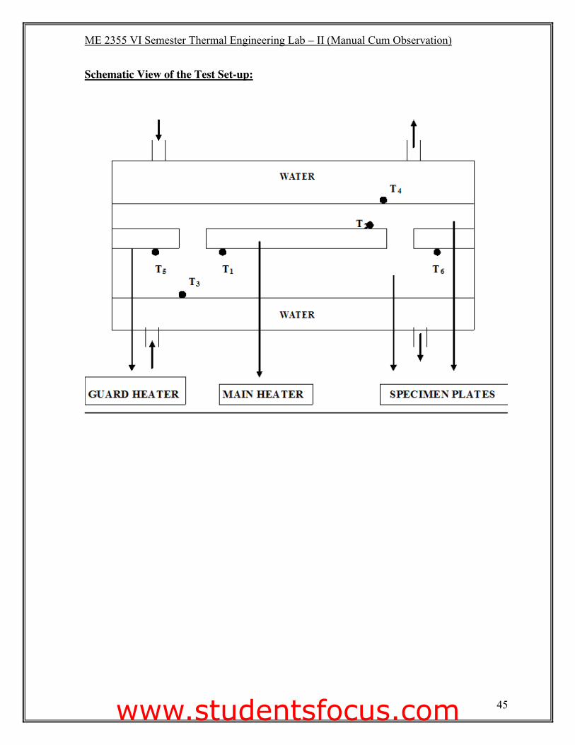
Theory:
The heater plate is surrounded by a heating ring for stabilizing the temperature of the primary
heater and to prevent heat jobs radially around its edges. The primary and guard heater are
made up of mica sheets in which is a would closely spaced Nichrome wire and packed with
upper and lower mica sheets. These heaters together form a flat which together with upper
and lower copper plates and rings form the heater plate assembly.
Two thermocouples are used to measure the hot face temperature at the upper and lower
central heater assembly copper plates. Two more thermocouples are used to check balance in
both the heater inputs.
Specimens are held between the heater and cooling unit on each side of the apparatus.
Thermocouples No.5 and No. 6 measure the temperature of the upper cooling plate and lower
cooling plate respectively.
The heater plate assembly together with cooling plates and specimen held in position by 3
vertical studs and nuts on a base plate are shown in the assembly drawing.
The cooling chamber is a composite assembly of grooved aluminum casting and aluminum
cover with entry and exit adaptors for water inlet and outlet.
www.studentsfocus.com
ME 2355 VI Semester Thermal Engineering Lab – II (Manual Cum Observation)
43
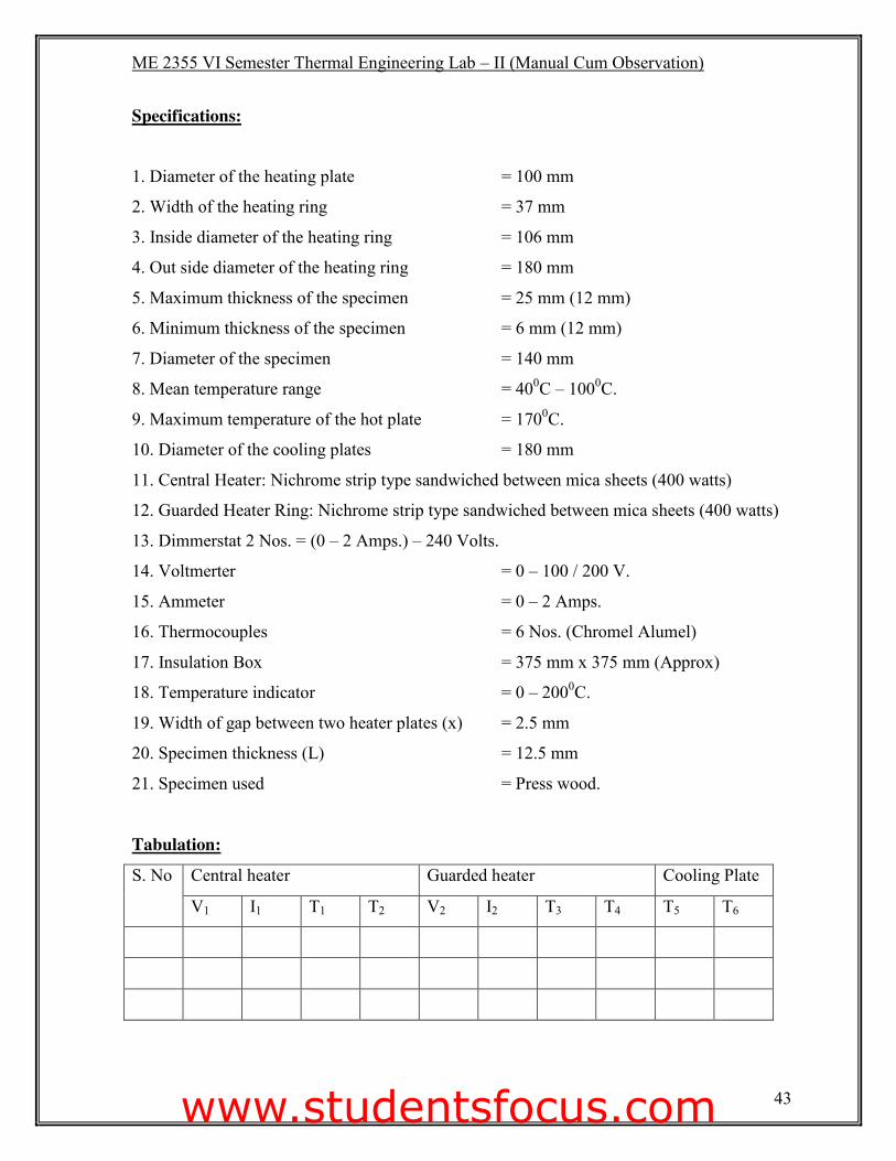
Specifications:
1. Diameter of the heating plate = 100 mm
2. Width of the heating ring = 37 mm
3. Inside diameter of the heating ring = 106 mm
4. Out side diameter of the heating ring = 180 mm
5. Maximum thickness of the specimen = 25 mm (12 mm)
6. Minimum thickness of the specimen = 6 mm (12 mm)
7. Diameter of the specimen = 140 mm
8. Mean temperature range = 400C – 1000C.
9. Maximum temperature of the hot plate = 1700C.
10. Diameter of the cooling plates = 180 mm
11. Central Heater: Nichrome strip type sandwiched between mica sheets (400 watts)
12. Guarded Heater Ring: Nichrome strip type sandwiched between mica sheets (400 watts)
13. Dimmerstat 2 Nos. = (0 – 2 Amps.) – 240 Volts.
14. Voltmerter = 0 – 100 / 200 V.
15. Ammeter = 0 – 2 Amps.
16. Thermocouples = 6 Nos. (Chromel Alumel)
17. Insulation Box = 375 mm x 375 mm (Approx)
18. Temperature indicator = 0 – 2000C.
19. Width of gap between two heater plates (x) = 2.5 mm
20. Specimen thickness (L) = 12.5 mm
21. Specimen used = Press wood.
Tabulation:
S. No Central heater Guarded heater Cooling Plate
V1 I1 T1 T2 V2 I2 T3 T4 T5 T6
www.studentsfocus.com
ME 2355 VI Semester Thermal Engineering Lab – II (Manual Cum Observation)
44
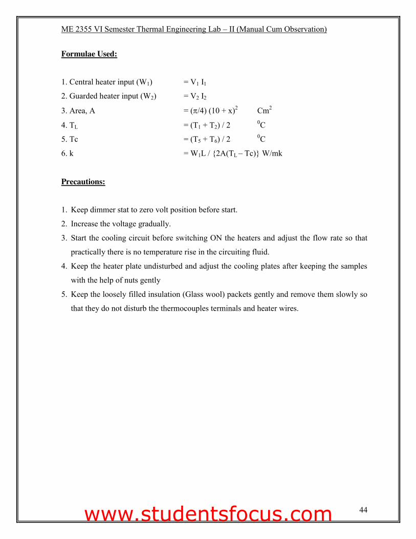
Formulae Used:
1. Central heater input (W1) = V1 I1
2. Guarded heater input (W2) = V2 I2
3. Area, A = (S/4) (10 + x)2 Cm2
4. TL = (T1 + T2) / 2 0C
5. Tc = (T5 + T6) / 2 0C
6. k = W1L / {2A(TL – Tc)} W/mk
Precautions:
1. Keep dimmer stat to zero volt position before start.
2. Increase the voltage gradually.
3. Start the cooling circuit before switching ON the heaters and adjust the flow rate so that
practically there is no temperature rise in the circuiting fluid.
4. Keep the heater plate undisturbed and adjust the cooling plates after keeping the samples
with the help of nuts gently
5. Keep the loosely filled insulation (Glass wool) packets gently and remove them slowly so
that they do not disturb the thermocouples terminals and heater wires.
www.studentsfocus.com
ME 2355 VI Semester Thermal Engineering Lab – II (Manual Cum Observation)
45
Schematic View of the Test Set-up:
www.studentsfocus.com
ME 2355 VI Semester Thermal Engineering Lab – II (Manual Cum Observation)
46
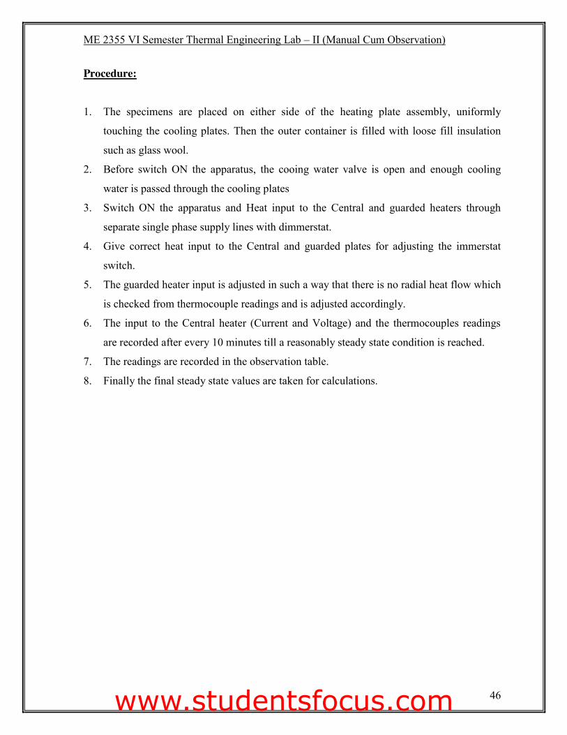
Procedure:
1. The specimens are placed on either side of the heating plate assembly, uniformly
touching the cooling plates. Then the outer container is filled with loose fill insulation
such as glass wool.
2. Before switch ON the apparatus, the cooing water valve is open and enough cooling
water is passed through the cooling plates
3. Switch ON the apparatus and Heat input to the Central and guarded heaters through
separate single phase supply lines with dimmerstat.
4. Give correct heat input to the Central and guarded plates for adjusting the immerstat
switch.
5. The guarded heater input is adjusted in such a way that there is no radial heat flow which
is checked from thermocouple readings and is adjusted accordingly.
6. The input to the Central heater (Current and Voltage) and the thermocouples readings
are recorded after every 10 minutes till a reasonably steady state condition is reached.
7. The readings are recorded in the observation table.
8. Finally the final steady state values are taken for calculations.
www.studentsfocus.com

ME 2355 VI Semester Thermal Engineering Lab – II (Manual Cum Observation)
47
Model Calculation:
www.studentsfocus.com
ME 2355 VI Semester Thermal Engineering Lab – II (Manual Cum Observation)
48
Result: Thus the experiment was done and thermal conductivity of given material was found to be
k = ___________________ w /mk.
Faculty Signature:
www.studentsfocus.com

ME 2355 VI Semester Thermal Engineering Lab – II (Manual Cum Observation)
49
www.studentsfocus.com
ME 2355 VI Semester Thermal Engineering Lab – II (Manual Cum Observation)
50
Ex: No: STEFAN BOLTSMAN APPARATUS Date:
Aim:
To determine the Stefan Boltzman Constant by using boltzman apparatus.
Apparatus Required: (i) Thermometer
(ii) Electric Heater
(iii) Stop watch
(iv) Geyser water
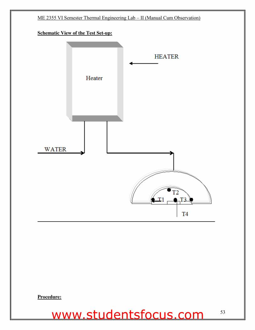
Theory: The apparatus is centered on flanged copper hemisphere B fixed on a flat non-conducting
plate A. The outer surface of B is enclosed in a metal water jacket used to heat B to some
suitable constant temperature. The hemispherical shape of B is chosen solely on the grounds
that it simplifies the task of draining water between B & C. Four chromel alumel
thermocouples are attached to various points on surface of B to measure its mean
temperature.
The disc D, which is mounted in an insulating bakelite sleeve S is fitted in a hole drilled in
the centre of base plate A. The base of S is conveniently supported from under side of A. A
chromel alumel thermocouple is used to measure the temperature of D (T5). The
thermocouple is mounted on the disc to study the rise of its temperature.
When the disc is inserted at the temperature T5 (T5 > T i.e the temperature of the enclosure),
the response of temperature change of disc with time is used to calculate the Stefan Boltzman
constant.
www.studentsfocus.com
ME 2355 VI Semester Thermal Engineering Lab – II (Manual Cum Observation)
51
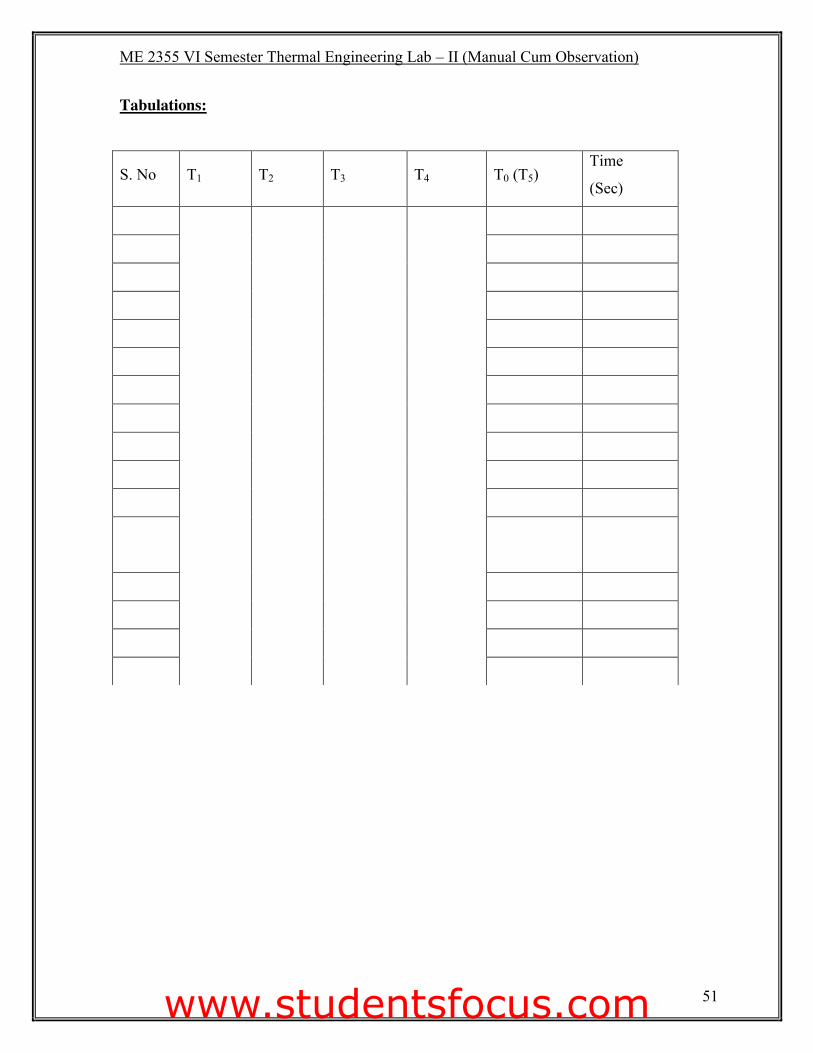
Tabulations:
S. No T1 T2 T3 T4 T0 (T5) Time
(Sec)
www.studentsfocus.com
ME 2355 VI Semester Thermal Engineering Lab – II (Manual Cum Observation)
52
Specifications:
1. Hemispherical enclosure diameter = 200 mm
2. Suitable sized water jacket for hemisphere.
3. Base plate, bakelite diameter = 240 mm
4. Sleeve size, diameter = 44 mm
5. Fixing arrangement for sleeve
6. Test disc, diameter = 20 mm
7. Mass of test disc = 0.008 kg
8. Specific heat, s of the test disc = 0.41868 kJ / Kg 0C
= (or) 0.1 Kcal / kg 0C
9. No. of thermocouples mounted on B = 4 Nos.
10. No. of thermocouples mounted on D = 1 No.
11. Temperature indicator digital 0.10C L.C 0 - 2000C with built-in cold junction
compensation and a timer set for 5 sec. to display temperature rise of the disc.
12. Immersion water heater of suitable capacity = 1.4 kW.
13. Tank for hot water.
Precautions:
Start the cooling circuit before switching ON the heaters (geyser) and adjust the flow rate so
that practically there is no temperature rise in the circuiting fluid.
Formulae Used:
Stefan Boltzman constant = V� = {mcp ( dT / dt)t = 0} / A ( Te4 – Ta4)
Where, A = area of the disc
Te = Emitter temperature (average of T1, T2, T3 & T4)
Ta = Absorber temperature = T0
dT / dt find the slope from the graph, Temperature T in Y axis, and time t in X axis.
www.studentsfocus.com
ME 2355 VI Semester Thermal Engineering Lab – II (Manual Cum Observation)
53
Schematic View of the Test Set-up:
Procedure:
www.studentsfocus.com
ME 2355 VI Semester Thermal Engineering Lab – II (Manual Cum Observation)
54
1. The water in the tank by the immersion heater up to a temperature of about 900C.
2. The disc, D is removed before pouring the hot water in the jacket.
3. The hot water is poured in the water jacket.
4. The hemispherical enclosure B and A will come to some uniform temperature T in short
time after filling the hot water in the jacket. The thermal inertia of hot water is quite
adequate to present significant cooling in the time required to conduct the experiment.
5. The enclosure will soon come to thermal equilibrium conditions.
6. The disc D is now inserted in A at a time when its temperature is saying T5 (to be sensed
by a separate thermocouple).
www.studentsfocus.com

ME 2355 VI Semester Thermal Engineering Lab – II (Manual Cum Observation)
55
Model Calculation:
www.studentsfocus.com
ME 2355 VI Semester Thermal Engineering Lab – II (Manual Cum Observation)
56
Result: The Stefan Boltzman constant was found out to be = _______________________ m/m2k4.
Faculty Signature:
www.studentsfocus.com

ME 2355 VI Semester Thermal Engineering Lab – II (Manual Cum Observation)
57
www.studentsfocus.com
ME 2355 VI Semester Thermal Engineering Lab – II (Manual Cum Observation)
58
Ex: No: PARALLEL FLOW AND COUNTER FLOW HEAT EXCHANGER Date:
Aim:
To determine the values of effectiveness of heat exchanger for parallel and counter flow.
Apparatus required: (i) Experimental Setup
(ii) Stop watch
(iii) Thermometer
Theory:
Heat exchangers are classified in three categories:
1. Transfer type
2. Storage type
3. Direct contact type.
A transfer type of heat exchanger is one which both fluids pass simultaneously through the
device and heat is transferred through separating walls. In practice, most of the heat
exchangers used are transfer type one.
The transfer type exchangers are further classified accordant to flow arrangements as:
i. PARRALLE FLOW in which fluids flow in the same direction.
ii. COUNTER FLOW in which fluids flow in opposite direction.
iii. CROSS FLOW in which fluids flow at right angles to each other.
The apparatus consist of a tube in tube type concentric tube heat exchanger. The hot fluid is
not water which is obtained from an electric geyser and it flows through the inner tube while
the cold fluid is cold water flowing through the annulus. The hot water flows always in one
direction and the flow rate is controlled by means of a gate vale. The cold water can be
admitted at one of the ends enabling the heat exchanger to run as a parallel flow apparatus or
a counter flow apparatus. This is done by valve operations.
www.studentsfocus.com
ME 2355 VI Semester Thermal Engineering Lab – II (Manual Cum Observation)
59
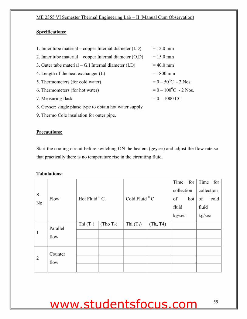
Specifications:
1. Inner tube material – copper Internal diameter (I.D) = 12.0 mm
2. Inner tube material – copper Internal diameter (O.D) = 15.0 mm
3. Outer tube material – G.I Internal diameter (I.D) = 40.0 mm
4. Length of the heat exchanger (L) = 1800 mm
5. Thermometers (for cold water) = 0 – 500C - 2 Nos.
6. Thermometers (for hot water) = 0 – 1000C - 2 Nos.
7. Measuring flask = 0 – 1000 CC.
8. Geyser: single phase type to obtain hot water supply
9. Thermo Cole insulation for outer pipe.
Precautions:
Start the cooling circuit before switching ON the heaters (geyser) and adjust the flow rate so
that practically there is no temperature rise in the circuiting fluid.
Tabulations:
S.
No Flow Hot Fluid 0 C. Cold Fluid 0 C
Time for
collection
of hot
fluid
kg/sec
Time for
collection
of cold
fluid
kg/sec
1 Parallel
flow
Thi (T1) (Tho T2) Thi (T3) (Tho T4)
2 Counter
flow
www.studentsfocus.com
ME 2355 VI Semester Thermal Engineering Lab – II (Manual Cum Observation)
60
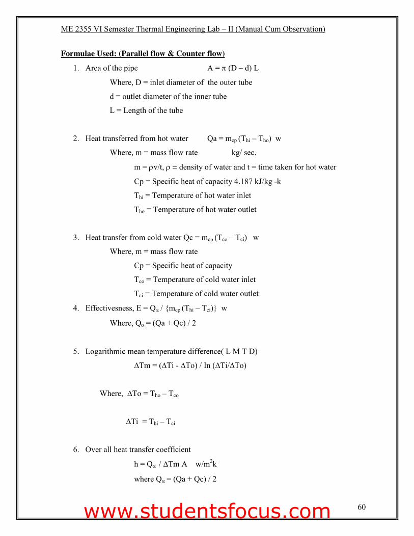
Formulae Used: (Parallel flow & Counter flow)
1. Area of the pipe A = S (D – d) L
Where, D = inlet diameter of the outer tube
d = outlet diameter of the inner tube
L = Length of the tube
2. Heat transferred from hot water Qa = mcp (Thi – Tho) w
Where, m = mass flow rate kg/ sec.
m = Uv/t, U� �density of water and t = time taken for hot water
Cp = Specific heat of capacity 4.187 kJ/kg -k
Thi = Temperature of hot water inlet
Tho = Temperature of hot water outlet
3. Heat transfer from cold water Qc = mcp (Tco – Tci) w
Where, m = mass flow rate
Cp = Specific heat of capacity
Tco = Temperature of cold water inlet
Tci = Temperature of cold water outlet
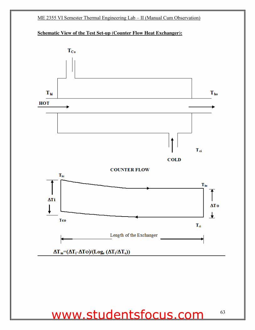
4. Effectivesness, E = QD / {mcp (Thi – Tci)} w
Where, QD = (Qa + Qc) / 2
5. Logarithmic mean temperature difference( L M T D)
∆Tm = (∆Ti - ∆To) / In (∆Ti/∆To)
Where, ∆To = Tho – Tco
∆Ti = Thi – Tci
6. Over all heat transfer coefficient
h = QD����∆Tm A w/m2k
where QD = (Qa + Qc) / 2
www.studentsfocus.com
ME 2355 VI Semester Thermal Engineering Lab – II (Manual Cum Observation)
61
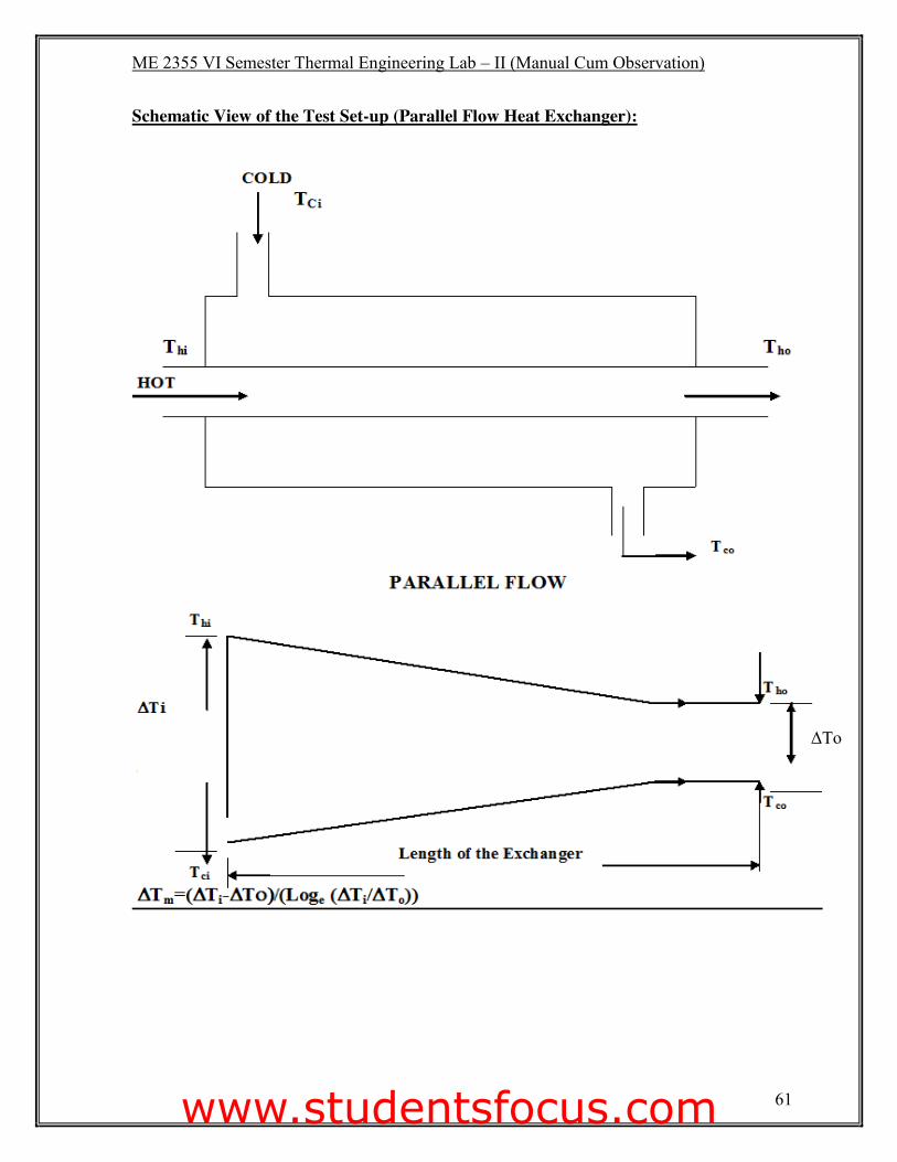
Schematic View of the Test Set-up (Parallel Flow Heat Exchanger):
ΔTo
www.studentsfocus.com
ME 2355 VI Semester Thermal Engineering Lab – II (Manual Cum Observation)
62
Procedure:
1. Place the thermometers in position and note down their readings when they are at room
temperature and no water is flowing at either side. This is required to correct the
temperature.
2. Start the flow on hot water side.
3. Start the flow through annulus and run the exchanger as parallel flow unit.
4. Put ON the geyser.
5. Adjust the flow rate on hot water side, between the ranges of 1.5 to 4 L/min.
6. Adjust the flow rate on cold water side between ranges of 3 to 8 L/min.
7. Keeping the flow rates same, wait till the steady state conditions are reached.
8. Record the temperatures on hot water and cold water side and also the flow rates
accurately.
9. Repeat the experiment with a counter flow under identical flow conditions.
10. Correct the temperatures by suitable correction obtained from initial readings of
thermometers.
www.studentsfocus.com
ME 2355 VI Semester Thermal Engineering Lab – II (Manual Cum Observation)
63
Schematic View of the Test Set-up (Counter Flow Heat Exchanger):
www.studentsfocus.com

ME 2355 VI Semester Thermal Engineering Lab – II (Manual Cum Observation)
64
Model Calculation:
www.studentsfocus.com

ME 2355 VI Semester Thermal Engineering Lab – II (Manual Cum Observation)
65
Model Calculation:
www.studentsfocus.com
ME 2355 VI Semester Thermal Engineering Lab – II (Manual Cum Observation)
66
Result: 1. The values of effectiveness of heat exchanger were found as
(i) Parallel flow = ________.
(ii) Counter flow = _________.
2. Over all heat exchanger (heat transfer coefficient)
(i) Parallel flow = ________.
(ii) Counter flow = _________.
Faculty Signature:
www.studentsfocus.com

ME 2355 VI Semester Thermal Engineering Lab – II (Manual Cum Observation)
67
www.studentsfocus.com
ME 2355 VI Semester Thermal Engineering Lab – II (Manual Cum Observation)
68
Ex: No: REFRIGERATION TEST RIG Date:
Aim: To conduct a load test on refrigeration test rig and determine the coefficient of performance
of refrigeration system.
Apparatus Required: (i) Thermometer
(ii) Electric Heater
(iii) Stop watch
(iv) Experimental setup
Description: 1. The test rig consist of compressor, condenser unit placed inside trolley and fitted with (i)
R-134a reciprocating compressor (ii) Air cooled condenser, (iii) Cooling fan for
condenser and (iv) Liquid receiver.
2. The chilled water calorimeter consisting of a refrigerated stainless steel vessel placed
inside an insulated wooden box and provided with (i) Evaporative coil, (ii) Stirrer, (iii)
Electric heater, (iv) Sensing bulb of a low temperature thermostat, (v) A high
temperature thermostat and (vi) A thermometer to measure the temperature of chilled
water. The above unit is located on the trolley behind front panel.
3. The front panel of the test rig consist of (i) Capillary expansion tube with isolation valve,
(ii) Thermostatic expansion valve and solenoid thermostat, solenoid switch, indicator
and isolating valve (iii) Drier cum strainer and sight glass, (iv) Thermostat at inlet and
outlet of both evaporator and condenser, (v) Pressure gauge at inlet and outlet of
evaporator and condenser,(vi) Main switch and compressor safety high pressure / low
pressure (HP/LP) cut-out, (vii) Heat power regulator switch and regulator, (viii) Energy
meter to measure the power consumed eithr by hater or by compressor.
www.studentsfocus.com
ME 2355 VI Semester Thermal Engineering Lab – II (Manual Cum Observation)
69
Specifications:
A. A compressor condenser unit placed inside trolley and fitted with 1. R-134a reciprocating compressor
2. Condenser
3. 0.5 hp, 220 V, single phase capacitor start induction motor with condenser cooling fan
4. A receiver with angle check valve
B. Chilled water calorimeter consisting of a refrigerated S.S vessel of ample capacity placed inside a well insulated wooden box and provided with
5. Evaporator coil
6. Stirrer
7. Electric heater 230 V, A.C.
8. The sensing bulb of low temperature thermostat.
9. A high temperature thermostat.
10. A Thermometer to measure the chilled water temperature
C. The front panel on which are mounted the following 11. Capillary expansion tube with isolating valve.
12. Thermostatic expansion valve and solenoid thermostat, solenoid switch, indicator and
isolating valve
13. Drier cum strainer and sight glass
14. Thermostat at inlet and outlet of both evaporator and condenser
15. Pressure gauge at inlet and outlet of evaporator and condenser
16. Main switch and compressor safety high pressure / low pressure (HP/LP) cut-out
17. Heat power regulator switch and regulator
18. Energy meter to measure the power consumed either by hater or by compressor.
www.studentsfocus.com
ME 2355 VI Semester Thermal Engineering Lab – II (Manual Cum Observation)
70
Precautions:
1. Make sure that the three pin main cable is properly earthed to avoid any electrical
shocks.
2. The heater regulator should be switched off whenever not in use. Heating water beyond
400C may lead to permanent damage of the entire system. A high temperature cut off
thermostat is provided in the water chiller, to cut off the heater beyond 300C.Check the
setting of the same before operation.
3. The (low pressure) LP cut-off is adjusted to cut on reading 10 psig. Do not alter this
setting.
4. The (high pressure) HP cut-off is adjusted to cut at 280 psig. Do not alter this setting.
5. The solenoid thermostat is adjusted to cut at 150C and cut in at 100C of the chilled water.
Do not alter the same.
6. The main switch contains a fuse unit inside. The same has to be rewired if blown of.
7. The space near the condenser should permit good ventilation to aid proper fan
performance.
8. The pressure gauges used are calibrated in psig: (the corresponding saturation
temperature are marked in 0 F on the dial for Freon-22 and is irrelevant here. Reliable
pressure gauges for Freon-12 use, calibrated in SI units, are not available.)
9. Hence the reading should be converted into absolute (psia) units by adding 14.7 and
dividing by 145 to obtain the pressure in MN/m2.e.g. P = x psig
= (x + 14.7) psia
= (x + 14.7) / 145 MN/m2 (MPa)
10. The water in the chiller is to be stirred properly for some time before taking readings T4
& T5.
www.studentsfocus.com
ME 2355 VI Semester Thermal Engineering Lab – II (Manual Cum Observation)
71
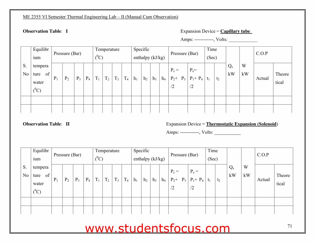
Observation Table: I Expansion Device = Capillary tube
Amps: ------------, Volts: ____________
Observation Table: II Expansion Device = Thermostatic Expansion (Solenoid)
Amps: ------------, Volts: ___________
S.
No
Equilibr
ium
tempera
ture of
water
(0C)
Pressure (Bar) Temperature
(0C)
Specific
enthalpy (kJ/kg) Pressure (Bar)
Time
(Sec)
Qe
kW
W
kW
C.O.P
P1 P2 P3 P4 T1 T2 T3 T4 h1 h2 h3 h4
Pc =
P2+ P3
/2
Pe=
P1+ P4
/2
t1 t2 Actual Theore
tical
S.
No
Equilibr
ium
tempera
ture of
water
(0C)
Pressure (Bar) Temperature
(0C)
Specific
enthalpy (kJ/kg) Pressure (Bar)
Time
(Sec)
Qe
kW
W
kW
C.O.P
P1 P2 P3 P4 T1 T2 T3 T4 h1 h2 h3 h4
Pc =
P2+ P3
/2
Pe =
P1+ P4
/2
t1 t2 Actual Theore
tical
www.studentsfocus.com
ME 2355 VI Semester Thermal Engineering Lab – II (Manual Cum Observation)
72
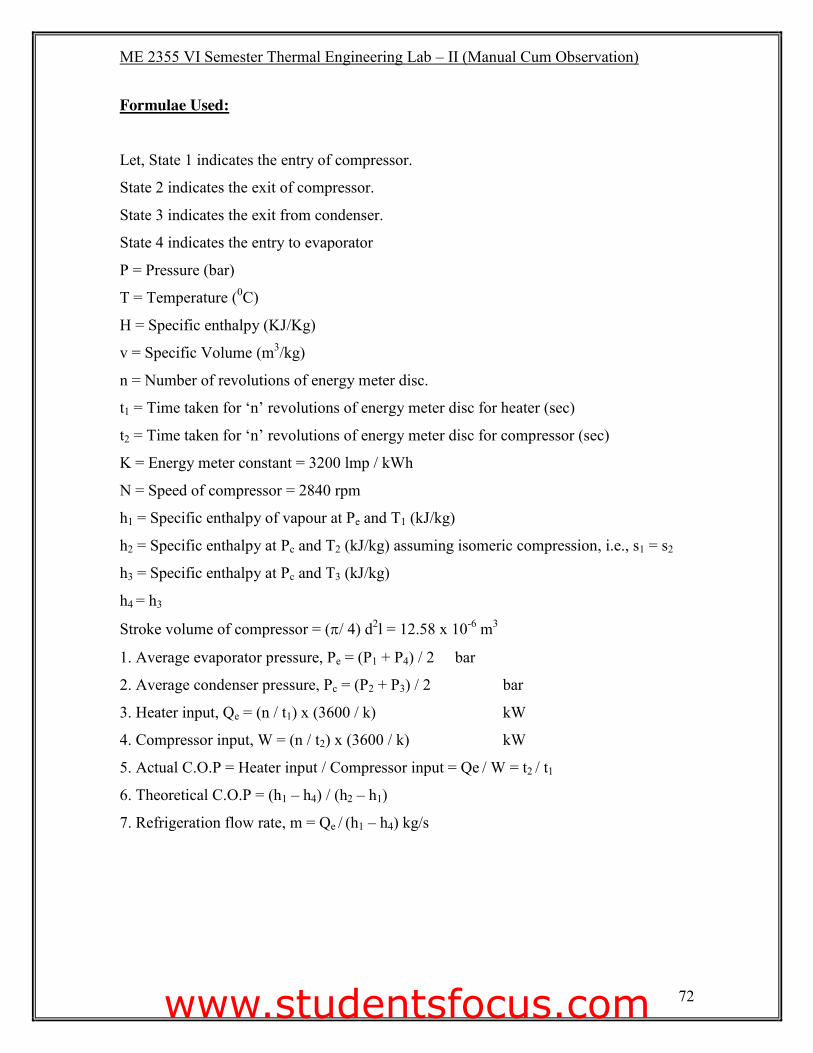
Formulae Used:
Let, State 1 indicates the entry of compressor.
State 2 indicates the exit of compressor.
State 3 indicates the exit from condenser.
State 4 indicates the entry to evaporator
P = Pressure (bar)
T = Temperature (0C)
H = Specific enthalpy (KJ/Kg)
v = Specific Volume (m3/kg)
n = Number of revolutions of energy meter disc.
t1 = Time taken for ‘n’ revolutions of energy meter disc for heater (sec)
t2 = Time taken for ‘n’ revolutions of energy meter disc for compressor (sec)
K = Energy meter constant = 3200 lmp / kWh
N = Speed of compressor = 2840 rpm
h1 = Specific enthalpy of vapour at Pe and T1 (kJ/kg)
h2 = Specific enthalpy at Pc and T2 (kJ/kg) assuming isomeric compression, i.e., s1 = s2
h3 = Specific enthalpy at Pc and T3 (kJ/kg)
h4 = h3
Stroke volume of compressor = (S/ 4) d2l = 12.58 x 10⁻⁶ m3
1. Average evaporator pressure, Pe = (P1 + P4) / 2 bar
2. Average condenser pressure, Pc = (P2 + P3) / 2 bar
3. Heater input, Qe = (n / t1) x (3600 / k) kW
4. Compressor input, W = (n / t2) x (3600 / k) kW
5. Actual C.O.P = Heater input / Compressor input = Qe / W = t2 / t1
6. Theoretical C.O.P = (h1 – h4) / (h2 – h1)
7. Refrigeration flow rate, m = Qe / (h1 – h4) kg/s
www.studentsfocus.com

ME 2355 VI Semester Thermal Engineering Lab – II (Manual Cum Observation)
73
Model Calculation:
www.studentsfocus.com
ME 2355 VI Semester Thermal Engineering Lab – II (Manual Cum Observation)
74
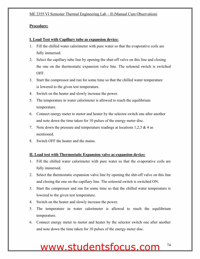
Procedure:
I. Load Test with Capillary tube as expansion device: 1. Fill the chilled water calorimeter with pure water so that the evaporative coils are
fully immersed.
2. Select the capillary tube line by opening the shut-off valve on this line and closing
the one on the thermostatic expansion valve line. The solenoid switch is switched
OFF.
3. Start the compressor and run for some time so that the chilled water temperature
is lowered to the given test temperature.
4. Switch on the heater and slowly increase the power.
5. The temperature in water calorimeter is allowed to reach the equilibrium
temperature.
6. Connect energy meter to motor and heater by the selector switch one after another
and note down the time taken for 10 pulses of the energy meter disc.
7. Note down the pressure and temperature readings at locations 1,2,3 & 4 as
mentioned.
8. Switch OFF the heater and the mains.
II. Load test with Thermostatic Expansion valve as expansion device: 1. Fill the chilled water calorimeter with pure water so that the evaporative coils are
fully immersed.
2. Select the thermostatic expansion valve line by opening the shit-off valve on this line
and closing the one on the capillary line. The solenoid switch is switched ON.
3. Start the compressor and run for some time so that the chilled water temperature is
lowered to the given test temperature.
4. Switch on the heater and slowly increase the power.
5. The temperature in water calorimeter is allowed to reach the equilibrium
temperature.
6. Connect energy meter to motor and heater by the selector switch one after another
and note down the time taken for 10 pulses of the energy meter disc.
www.studentsfocus.com

ME 2355 VI Semester Thermal Engineering Lab – II (Manual Cum Observation)
75
Model Calculation:
www.studentsfocus.com
ME 2355 VI Semester Thermal Engineering Lab – II (Manual Cum Observation)
76
7. Note down the pressure and temperature readings at locations 1, 2, 3 & 4 as
mentioned.
8. Switch OFF the heater and the mains.
Result:
The load test on a refrigeration test rig was conducted and the results are as follows.
1. Actual C.O.P. of the system =____________.
2. Rhetorical C.O.P. of the system = ___________.
3. Volumetric Efficiency = ___________.
Faculty Signature:
www.studentsfocus.com

ME 2355 VI Semester Thermal Engineering Lab – II (Manual Cum Observation)
77
www.studentsfocus.com
ME 2355 VI Semester Thermal Engineering Lab – II (Manual Cum Observation)
78
Ex: No: AIR CONDITIONING TEST RIG Date:
Aim:
To conduct a performance test on air conditioning test rig and determine the C.O.P. of air
conditioning system.
Apparatus Required: (i) Thermometer
(ii) Electric Heater
(iii) Stop watch
(iv) Digital anemometer
(v) Experimental setup
Description:
The test rig consist of
1. An air duct support of stand
2. A Blower to set up air flow through the duct along with a speed control to vary the
velocity of air.
3. A heater to rise the air temperature with regulator and energy meter.
4. Water spray, collecting tray, reservoir with gauge pump.
5. Wet and dry bulb bi-metallic dial type thermometer at stations 1, 2,3 &4.
(i.e., before heater, after heater or before sprayer, after sprayer or before cooing coil,
after cooling coil).
4. The test rig consist of compressor, condenser unit placed inside trolley and fitted
with (i) Freon-22 (CCI2F2) reciprocating compressor (ii) Air cooled condenser, (iii)
Cooling fan for condenser and (iv) Liquid receiver.
www.studentsfocus.com
ME 2355 VI Semester Thermal Engineering Lab – II (Manual Cum Observation)
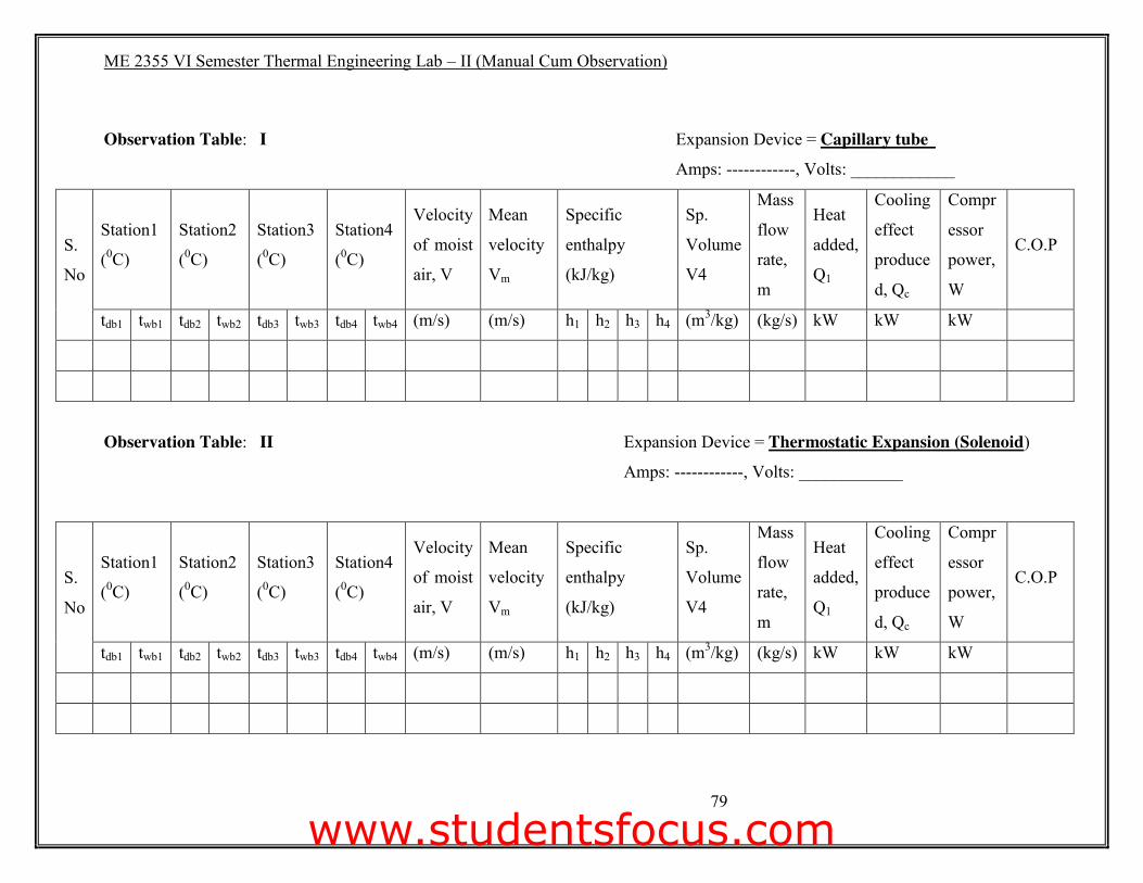
79
Observation Table: I Expansion Device = Capillary tube
Amps: ------------, Volts: ____________
S.
No
Station1
(0C)
Station2
(0C)
Station3
(0C)
Station4
(0C)
Velocity
of moist
air, V
Mean
velocity
Vm
Specific
enthalpy
(kJ/kg)
Sp.
Volume
V4
Mass
flow
rate,
m
Heat
added,
Q1
Cooling
effect
produce
d, Qc
Compr
essor
power,
W
C.O.P
tdb1 twb1 tdb2 twb2 tdb3 twb3 tdb4 twb4 (m/s) (m/s) h1 h2 h3 h4 (m3/kg) (kg/s) kW kW kW
Observation Table: II Expansion Device = Thermostatic Expansion (Solenoid)
Amps: ------------, Volts: ____________
S.
No
Station1
(0C)
Station2
(0C)
Station3
(0C)
Station4
(0C)
Velocity
of moist
air, V
Mean
velocity
Vm
Specific
enthalpy
(kJ/kg)
Sp.
Volume
V4
Mass
flow
rate,
m
Heat
added,
Q1
Cooling
effect
produce
d, Qc
Compr
essor
power,
W
C.O.P
tdb1 twb1 tdb2 twb2 tdb3 twb3 tdb4 twb4 (m/s) (m/s) h1 h2 h3 h4 (m3/kg) (kg/s) kW kW kW
www.studentsfocus.com
ME 2355 VI Semester Thermal Engineering Lab – II (Manual Cum Observation)
80
Precautions:
1. In case of low voltage motor may be overloaded, get heated up and the coils may be
burnt up. Hence avoid operation at voltage less than 220 V. If necessary use a
stabilizer of 2 kw only for the motor circuit.
2. Natural air currents in the room if in the direction of air duct may defect the
experimental results and hence the duct should be placed such that no wind from
doors, windows, fan and cooling air from other test rigs are directly incline with the
duct. Any cross currents should only aid the condenser fan and should not oppose it
as otherwise the delivery pressure of the refrigerating systems will increase beyond
240 psi.
3. Never exceed dry bulb temperatures of 400C after the heater (station 2) otherwise the
air duct may be damaged.
4. Do not operate heater without operating cooler also, otherwise the vapour pressure
thermometer may exceed its maximum of 320C and calibration may be affected.
5. Fan is connected to the main switch so that it is always in operation. Never operate
when fan is not running this will lead to rise in temperature at the heater and may
damage the heater and the air duct.
6. After completing experiments always allow the fan only to operate for at least 15
minutes so that their duct is cooled to room temperature and is also dried, otherwise
the duct will be damaged.
7. Never run the pump without water in the reservoir, otherwise pump seals will be
damaged. A strainer is placed inside the reservoir at the top. This may have to the
cleaned when necessary.
8. Do not open the gate valve fully otherwise water may be splashed outside and the
waster measurement may be in error.
9. If the low pressure cut out comes in to action, it means that the Freon charge is
insufficient and may have to be filled up. The suction pressure should never go
below 2 psi as otherwise the compressor seals will be damaged and air and moisture
may enter the system.
www.studentsfocus.com
ME 2355 VI Semester Thermal Engineering Lab – II (Manual Cum Observation)
81
10. The refrigerant strainer placed on the front panel should always be warm. If it cools
and moisture condenser on it, then the strainer might have to be charged by an
experienced refrigeration mechanics.
11. The refrigerating system can work continuously for 2 hours, however if the room
temperature is above 250C the condenser may be heated up and the delivery
pressure may rise. Do not exceed 240 psi. Pour one or two glasses of drinking water
over the fins of the condenser in order to reduce the delivery pressure.
12. After some months of operation the compressor may have to be topped up with oil
and some quantity of Freon-22 may have to be charged by an experienced
mechanics.
13. See that distilled water is filled up in the plastic dishes provided under the wet bulb
thermometers and that the wicks are in tact otherwise erroneous readings may be
obtained. These thermometers will show correct readings only when the fan is in
operation.
14. The inside of air duct and all metal parts should be painted at least once a year to
avoid moisture and corrosion damage.
www.studentsfocus.com
ME 2355 VI Semester Thermal Engineering Lab – II (Manual Cum Observation)
82
Formulae Used:
1. Corresponding to the dry and wet bulb temperature at all the stations obtain the
specific enthalpy and specific humidity values from psychometric chart.
i.e., h1 and w1 at tb1 and tw1 and so on.
2. Air flow rate, ma = (A x V) / v4 kg / sec
Where, A = Area of duct at outlet in m2 (0.46 m x 0.086 m)
V = Air velocity ( m / sec)
V4 = Specific volume of moist air at station 4 using psychometric chart
m3/kg
3. Heat added, Q1 = ma (h2 – h1) kW
Where, h1 = Specific enthalpy at station 1 kJ/kg
h2 = Specific enthalpy at station 2 kJ/kg
4. Moisture added from psychrometric chart, mw1 = ma (w3-w2) kg / sec.
Where, w3 = Specific humidity at station 3
w2 = Specific humidity at station 2
5. Compressor power, W = (n / t) x (3600 / k) kW.
Where, n = No. of pulses of energy meter disc
t = Time taken for ‘n’ no. of pulses (sec)
k = Energy meter constant (3200 lmp / kW-hr)
6. Actual C.O.P = Cooling effect produced on air / Compressor power.
7. Cooling effect produced on air, Qe = ma (h3 – h4) kW.
Where, h3 = Specific enthalpy at state 3 kJ/kg
h4 = Specific enthalpy at state 4 kJ/kg
8. Moisture condensed, mcl = ma (w3 – w4) kg/sec
Where, w3 = Specific humidity at station 3
w4 = Specific humidity at station 4
9. Draw the psychrometric process.
www.studentsfocus.com

ME 2355 VI Semester Thermal Engineering Lab – II (Manual Cum Observation)
83
Model Calculation:
www.studentsfocus.com
ME 2355 VI Semester Thermal Engineering Lab – II (Manual Cum Observation)
84
Procedure:
1. Fill water in the wet bulb temperature probe trays.
2. Start the main.
3. Start the blower and run it the required speed by keeping the speed regulator at
position.
4. Start the spray pump and open the gate valve suitably.
5. Start the heater.
6. Select the expansion device (Capillary tube / Thermostatic expansion valve) 7. Start the cooling compressor.
8. Wait for some time till thermometers shown practically constant readings and note
down the following readings:
(i) Dry bulb temperatures tdb1, tdb2, tdb3, tdb4.
(ii) Wet bulb temperatures twb1, twb2, twb3, twb4.
(iii) Spray water temperature, ts
(iv) Surface temperature of cooler, tm ( at control panel)
(v) Pressure gauge reading, pd ( at control panel)
(vi) Compound gauge reading, Ps ( at control panel)
(vii) Level reduction’l’ in spray reservoir (mm) during 5 min.
(viii) Amount of condensate collected ‘lc’, in a measuring jar at cooler tray during a
run of 5 minutes at constant conditions.
(ix) Time in second ‘SH’ for 10 pulses of the energy meter disc connected to the
heater.
(x) Time in seconds Sc for 10 pulses of the energy meter disc connected to cooler
compressor.
9. Repeat the above procedures for four more different settings of the fan Regulator
(Position 1,2,3,4 & 5). If sensible cooling range is narrow, then switch off the spray
and repeat as above. If the atmosphere is cool, the heater may be set for greater
dissipation. If more readings are required for cooling below dew point and
dehumidification switch off heater and repeat procedure.
10. Switch OFF all the mains.
www.studentsfocus.com

ME 2355 VI Semester Thermal Engineering Lab – II (Manual Cum Observation)
85
Model Calculation:
www.studentsfocus.com
ME 2355 VI Semester Thermal Engineering Lab – II (Manual Cum Observation)
86
Caution:
Heater regulator should not be adjusted beyond the position where dry bulb temperature
at station 2 may exceed 400C.
Result:
The Load test on the AIR CONDITIONING TEST RIG was conducted and the results
are as follows.
1. Actual C.O.P of the system = ______________.
Faculty Signature:
www.studentsfocus.com

VI Semester Thermal Engineering Lab – II (Manual Cum Observation)
87
www.studentsfocus.com
VI Semester Thermal Engineering Lab – II (Manual Cum Observation)
88
Ex: No: LOAD TEST ON AIR COMPRESSOR Date: Aim:
To conduct a load test on the 2 - stage reciprocating air compressor to determine the
isothermal and volumetric Efficiencies at various delivery pressures.
Apparatus Required:
* Air compressor with accessories.
* Stop watch.
Description:
Two stage air compressors is a reciprocating type driven by a prime mover. The test rig
consist of a base on which the tank is mounted. The outlet of the compressor is connected
to the receiver. The suction is connected to air tank with a calibrated orifice plate through
a water manometer. The input to the motor is recorded by an energy meter. The
temperature and pressure of the air compressed is indicated by a thermometer and
pressure gauge.
www.studentsfocus.com
VI Semester Thermal Engineering Lab – II (Manual Cum Observation)
89
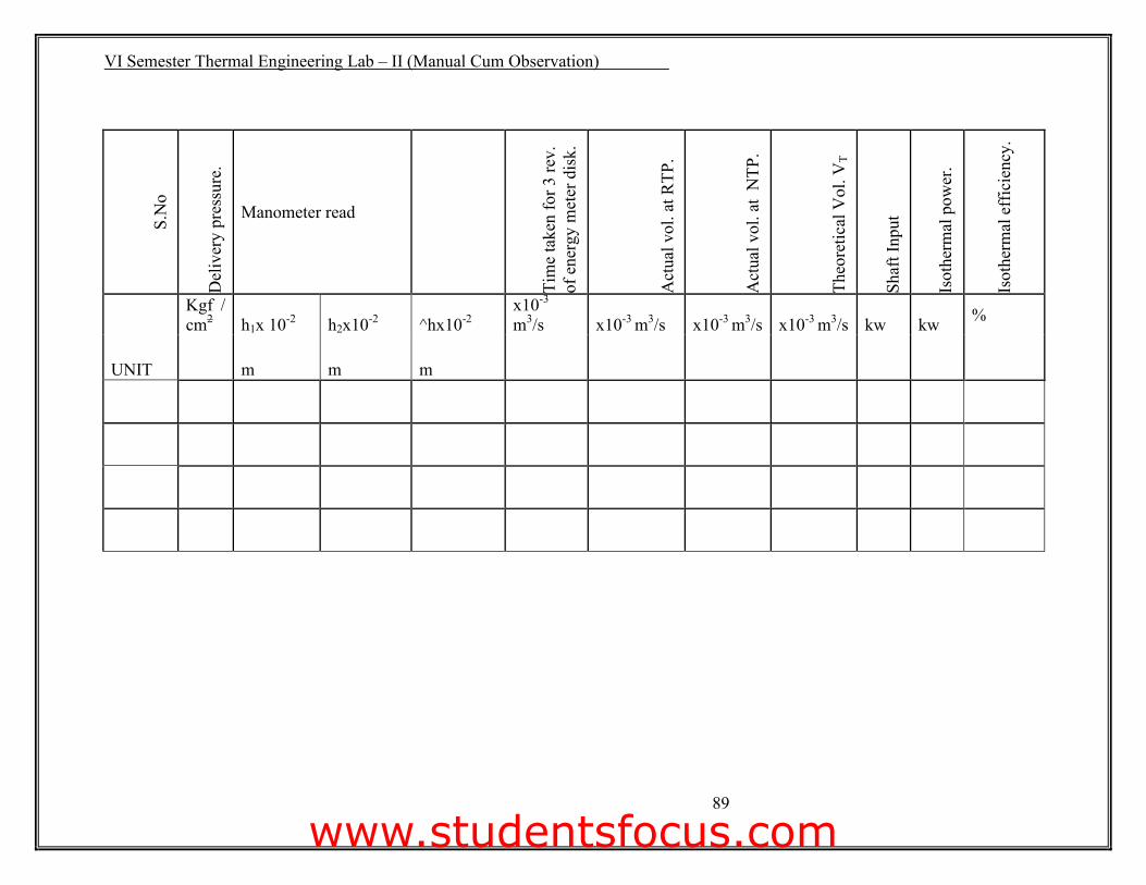
S.N
o
Del
iver
y pr
essu
re.
Manometer read
Tim
e ta
ken
for 3
rev.
of
ene
rgy
met
er d
isk.
Act
ual v
ol. a
t RTP
.
Act
ual v
ol. a
t N
TP.
Theo
retic
al V
ol. V
T
Shaf
t Inp
ut
Isot
herm
al p
ower
.
Isot
herm
al e
ffic
ienc
y.
Kgf / cm2 h1x 10-2 h2x10-2 ^hx10-2
x10-3
m3/s x10-3 m3/s x10-3 m3/s x10-3 m3/s kw kw %
UNIT m m m
www.studentsfocus.com
VI Semester Thermal Engineering Lab – II (Manual Cum Observation)
90
Specifications: 1. Air compressor:
* LP Bore, DLP = 63.0 mm.
* HP Bore, DHP = 79.0 mm.
* Stroke, L = 80.0 mm.
* Speed, N = 1440 rpm (5 HP)
* Effective radius = 0.193 m
2. Air receiver capacity = 0.33 m3
3. Orifice, diameter, d0 = 12 mm
4. Orifice area,. A0 : Sd02 / 4 = ----------- m2
5. Coefficient of discharge C d. = 0.6
6. Energy-meter constant = 200 rev / kWh.
Precautions: 1. Check whether manometer is filled with water up to the required level.
2. The maximum pressure in the receiver tank should not exceed 12 kg / cm2
Procedure:
1. Ensure zero gauge pressure in the tank.
2. The compressor is started. The receiver pressure gauge is read for a particular
pressure.
3. The pressure is maintained constant by adjusting the outlet valve.
4. Note down the manometer reading and time taken for 3 revolution of the energy
meter disc.
5. Repeat the same procedure for various pressures.
6. Stop the compressor motor and release the pressure in receiver.
www.studentsfocus.com
VI Semester Thermal Engineering Lab – II (Manual Cum Observation)
91
Model Calculation:
www.studentsfocus.com
VI Semester Thermal Engineering Lab – II (Manual Cum Observation)
92
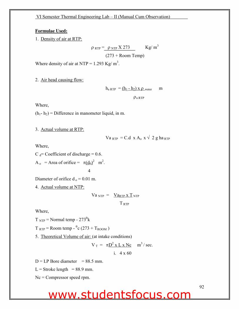
Formulae Used: 1. Density of air at RTP:
U RTP = U NTP X 273 Kg/ m3
(273 + Room Temp)
Where density of air at NTP = 1.293 Kg/ m3.
2. Air head causing flow:
ha RTP = (h1 - h2) x U water m
Ua RTP
Where,
(h1- h2) = Difference in manometer liquid, in m.
3. Actual volume at RTP:
Va RTP = C.d x Ao x � 2 g ha RTP
Where,
C d= Coefficient of discharge = 0.6.
A o = Area of orifice = S(d0)2 m2.
4
Diameter of orifice d o = 0.01 m.
4. Actual volume at NTP:
Va NTP = VaRTP x T NTP
T RTP
Where,
T NTP = Normal temp - 273Tk
T RTP = Room temp - Tc (273 + TROOM )
5. Theoretical Volume of air: (at intake conditions)
V T = SD2 x L x Nc m3 / sec.
i. 4 x 60
D = LP Bore diameter = 88.5 mm.
L = Stroke length = 88.9 mm.
Nc = Compressor speed rpm.
www.studentsfocus.com

VI Semester Thermal Engineering Lab – II (Manual Cum Observation)
93
Model Calculation:
www.studentsfocus.com
VI Semester Thermal Engineering Lab – II (Manual Cum Observation)
94
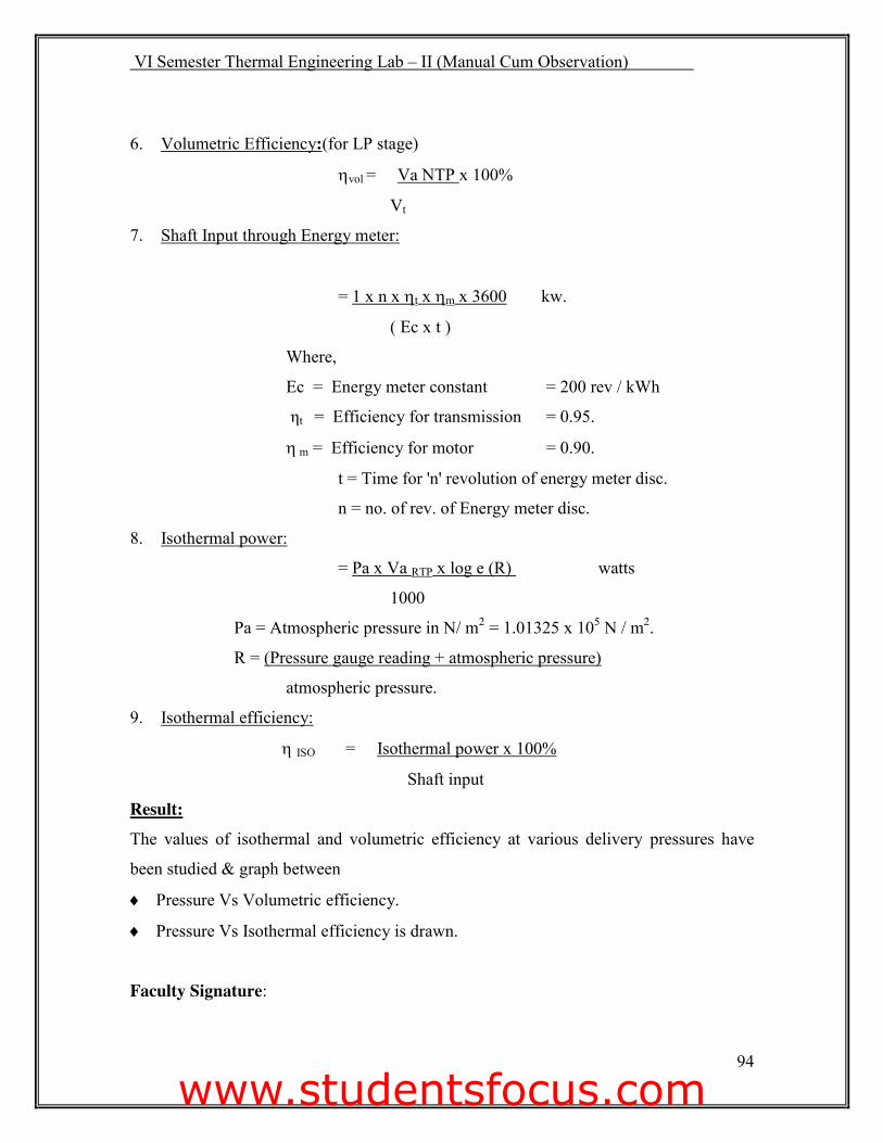
6. Volumetric Efficiency:(for LP stage)
Kvol = Va NTP x 100%
Vt
7. Shaft Input through Energy meter:
= 1 x n x Kt x Km x 3600 kw.
( Ec x t )
Where,
Ec = Energy meter constant = 200 rev / kWh
ηt = Efficiency for transmission = 0.95.
K m = Efficiency for motor = 0.90.
t = Time for 'n' revolution of energy meter disc.
n = no. of rev. of Energy meter disc.
8. Isothermal power:
= Pa x Va RTP x log e (R) watts
1000
Pa = Atmospheric pressure in N/ m2 = 1.01325 x 10⁵ N / m2.
R = (Pressure gauge reading + atmospheric pressure)
atmospheric pressure.
9. Isothermal efficiency:
K ISO = Isothermal power x 100%
Shaft input
Result: The values of isothermal and volumetric efficiency at various delivery pressures have
been studied & graph between
i Pressure Vs Volumetric efficiency.
i Pressure Vs Isothermal efficiency is drawn. Faculty Signature:
www.studentsfocus.com