Embed Size (px)
Citation preview

Design and prototyping of a new synchronization system with stability at femtoseconds
Ming LiuElectronics Group, Division of Beam Diagnostics & Control Technology
Shanghai Synchrotron Radiation Facility

束测控制部电子学组Electronics Group, Beam Instrumentation & Control Division
Outline
• System design• Preliminary result• Future plan

束测控制部电子学组Electronics Group, Beam Instrumentation & Control Division
Jun. 2016Implemented at damping
ring of SuperKEKB.
Mar. 2015Development of
femtosecond timing system began.
Dec. 2014Standalone modules for
Brazil Sirius delivered.
Jul. 2012Version-II development
completed.
Aug. 20101st test on site succeeded
@ PLS-II
Dec. 2009Version-I development
completed.
10-year development history of electronic timing system at SSRF
Sep. 2007Development began.

束测控制部电子学组Electronics Group, Beam Instrumentation & Control Division
• The development of the electronic timing system has encountered its bottleneck.
Phase shift ~ 35 ps/℃ Jitter ~ 6 ps

束测控制部电子学组Electronics Group, Beam Instrumentation & Control Division
The goal of the system• The short-term jitter of the transmitted RF signal: 10fs;
• The long-term drift: 40 fs.

束测控制部电子学组Electronics Group, Beam Instrumentation & Control Division
System designVery fine phase delay is detected based on the theory of Michelson interference.
RF reference is recovered from fiber link, not rely on LLRF.
Full fiber optic network. Fanoutdistributed RF reference to devices around big facility.
Traditional event timing system is integrated to improve the stability.
Feature

束测控制部电子学组Electronics Group, Beam Instrumentation & Control Division
System design
•A CW laser with narrow linewidth and low temperature drift provides carrier signal;•Phase drift is detected in the homemade electronics based on the interference theory;•Phase is compensated by optical delay modules according to PID algorithm;•Homemade electronics as test platform measure the stability of the transmitted signal.
束测控制部电子学组Electronics Group, Beam Instrumentation & Control Division
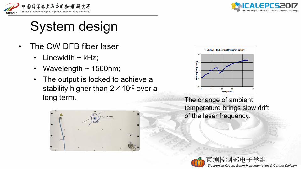
System design• The CW DFB fiber laser
• Linewidth ~ kHz;• Wavelength ~ 1560nm;• The output is locked to achieve a
stability higher than 2×10⁻⁹ over a long term. The change of ambient
temperature brings slow drift of the laser frequency.

束测控制部电子学组Electronics Group, Beam Instrumentation & Control Division
System design• Optical part of the system is based on the theory of Michelson interference
• Optical network provides THz bandwidth, low attenuation and electric isolation;• Since the carrier phase in THz converts to beat frequency phase in MHz, the
detection accuracy is improved by 6 orders of magnitude;• Ordinary single-mode fiber but not PM fiber is utilized to reduce the cost.
Frequency stabilizedCW laser
AM
AOFS FRM
Phase detection
PIDController
Recovered reference
signal
Reference signal
Transmitter Receiver
Optical delay modules
FRM

束测控制部电子学组Electronics Group, Beam Instrumentation & Control Division
• Hardware module design• Transmitter
• Modulate RF reference to laser carrier.
• Receiver• Both of detection and compensation are in receiver;• Hardware based PID algorithm allocates delay amounts to 2 delay modules;• RF signal conditioning and amplification.
• Fanout• Expansion of signal channels.
System design

束测控制部电子学组Electronics Group, Beam Instrumentation & Control Division
System design• Feedback quantities are calculated accurately in consideration of detected phase drift,
group delay fluctuation and so on.– Phase drift of RF reference is detected accurately in beat frequency signal;– Each fiber will be tested to obtain the dispersion parameters, and the feed forward
compensation is applied to the correcting value;– PID controller guarantees accurate outputs to the executive devices.
Phase detection
PIDController
Recovered reference
signalFiber stretcher
ODL
Dispersioncompensation
Modulated reference
signal
Beat frequency
signal

束测控制部电子学组Electronics Group, Beam Instrumentation & Control Division
Preliminary results• The results agree with the simulation.
– The recovered RF signal was lock to the original RF signal at the transmitter;
– The beat frequency signal was observed.

束测控制部电子学组Electronics Group, Beam Instrumentation & Control Division
Preliminary results• The phase drift of
optical modules due to ambient temperature change. (including laser, analog modulator, fiber coupler and photodiode but not long fiber).
• The phase drift of optical modules due to ambient temperature change. (including laser, analog modulator, fiber coupler photodiode and a fiber of 2km).

束测控制部电子学组Electronics Group, Beam Instrumentation & Control Division
Preliminary results• A software-based feedback scheme suppressed the phase drift to
around ~800fs, where only the coarse delay line was utilized.

束测控制部电子学组Electronics Group, Beam Instrumentation & Control Division
Future plan• Integration of event timing system.
• Timing events are transmitted along the same fiber;• Timing events could be stabilized against temperature change.

束测控制部电子学组Electronics Group, Beam Instrumentation & Control Division
Future plan
CW laser
Generator
Fanout
Receiver Receiver Receiver
RF reference
Repetition rate
μTCA
Recovered RF Reference
Event stream
Stabilizedclk & trig
Recovered RF Reference
Event stream
Recovered RF Reference
Event stream
• Integrated system structure.– The generator transmits modulated
RF reference and event stream through one fiber;
– The fanout distributes RF reference and event stream, and compensates phase drift of uplink;
– The receiver compensates phase drift of uplink, and recovers electric RF reference and optical event stream;
– EVR modules in μTCA chassis output stabilized clocks and triggers.